the BASIC Stamp BS2 with Range Finding Sensors - MyWeb at WIT
the BASIC Stamp BS2 with Range Finding Sensors - MyWeb at WIT
the BASIC Stamp BS2 with Range Finding Sensors - MyWeb at WIT

Create successful ePaper yourself
Turn your PDF publications into a flip-book with our unique Google optimized e-Paper software.
Integr<strong>at</strong>ing <strong>the</strong> <strong>BASIC</strong> <strong>Stamp</strong> <strong>BS2</strong> <strong>with</strong> <strong>Range</strong> <strong>Finding</strong> <strong>Sensors</strong> for<br />
Trackless Navig<strong>at</strong>ion<br />
ELEC471<br />
Spring 2009<br />
Max Nielsen<br />
Dan Brosnan<br />
Dana Howes<br />
April 29, 2009
This is a program for <strong>the</strong> <strong>BASIC</strong> stamp <strong>BS2</strong> to control two infrared distance measurement<br />
sensors, an ultrasonic distance measuring sensor (Parallax, ‘PING)))’ sensor), and an integr<strong>at</strong>ed bumper<br />
sensor, <strong>with</strong> <strong>the</strong> code to program a motor controller to control two individual motors for obstacle<br />
avoidance in a robotics applic<strong>at</strong>ion. The program for this is written, but will have explan<strong>at</strong>ions in<br />
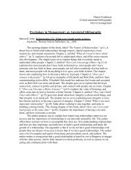
between <strong>the</strong> code. The actual code will be highlighted below. A diagram of <strong>the</strong> obstacle avoidance can<br />
be seen below in Figure 1.<br />
Ultrasonic Sensor<br />
IR sensors<br />
Figure 1 – Obstacle Avoidance Diagram
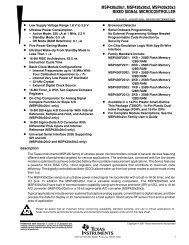
A photo of an applic<strong>at</strong>ion can be seen in Figure 2.<br />
The first part of this program defines <strong>the</strong> basic<br />
stamp module being used, and <strong>the</strong> language th<strong>at</strong> is being<br />
used. This is identified by <strong>the</strong> compiler, and helps to<br />
define <strong>the</strong> functions.<br />
' {$STAMP <strong>BS2</strong>}<br />
' {$P<strong>BASIC</strong> 2.5}<br />
The next part is a simple description of wh<strong>at</strong> <strong>the</strong><br />
program does. Anything after <strong>the</strong> apostrophe, “ ‘ “ mark<br />
will be recognized as a comment.<br />
'‐‐‐‐‐[ Program Description ]‐‐‐‐‐‐‐‐‐‐‐‐‐‐‐‐‐‐‐‐‐‐‐‐‐‐‐‐‐‐‐‐‐‐‐‐‐‐‐<br />
' This program demonstr<strong>at</strong>es reading <strong>the</strong> distance in<br />
centimeters from <strong>the</strong><br />
' Sharp GP2D12 Analog Distance Sensor. It also combines<br />
this <strong>with</strong> <strong>the</strong><br />
' PING))) Ultrasonic sensor from Parallax, and displays all values in both<br />
' inches and cm.<br />
Figure 2 – Picture of Robotic Applic<strong>at</strong>ion<br />
The next part of <strong>the</strong> program sets <strong>the</strong> I/O Definitions. It defines <strong>the</strong> variables to wh<strong>at</strong> I/O pin<br />
<strong>the</strong>y are plugged into. Again, to <strong>the</strong> right after <strong>the</strong> apostrophe is a comment <strong>with</strong> a description of wh<strong>at</strong><br />
each definition does. There is a repe<strong>at</strong>, one for <strong>the</strong> left infrared sensor, one is for <strong>the</strong> right infrared<br />
sensor.<br />
' ‐‐‐‐‐[ I/O Definitions ]‐‐‐‐‐‐‐‐‐‐‐‐‐‐‐‐‐‐‐‐‐‐‐‐‐‐‐‐‐‐‐‐‐‐‐‐‐‐‐‐‐‐‐‐‐‐‐‐‐<br />
Adc0831R PIN 0 ' ADC0831 Chip Select (ADC0831.1)<br />
AdcClockR PIN 1 ' ADC0831 Clock (ADC0831.7)<br />
AdcD<strong>at</strong>aR PIN 2 ' ADC0831 D<strong>at</strong>a (ADC0831.6)<br />
Adc0831L PIN 3 ' ADC0831 Chip Select (ADC0831.1)<br />
AdcClockL PIN 4 ' ADC0831 Clock (ADC0831.7)<br />
AdcD<strong>at</strong>aL PIN 5 ' ADC0831 D<strong>at</strong>a (ADC0831.6)<br />
To see how <strong>the</strong> infrared sensors work and how <strong>the</strong>y are connected, see Appendix A.<br />
The following is <strong>the</strong> variable definitions and <strong>the</strong> constants used to make conversions and<br />
calcul<strong>at</strong>ions from <strong>the</strong> analog IR sensors.<br />
' ‐‐‐‐‐[ Constants ]‐‐‐‐‐‐‐‐‐‐‐‐‐‐‐‐‐‐‐‐‐‐‐‐‐‐‐‐‐‐‐‐‐‐‐‐‐‐‐‐‐‐‐‐‐‐‐‐‐‐‐‐‐‐‐<br />
span CON 5 ' 5 cm Per D<strong>at</strong>a Point<br />
' ‐‐‐‐‐[ Variables ]‐‐‐‐‐‐‐‐‐‐‐‐‐‐‐‐‐‐‐‐‐‐‐‐‐‐‐‐‐‐‐‐‐‐‐‐‐‐‐‐‐‐‐‐‐‐‐‐‐‐‐‐‐‐‐<br />
resultR VAR Byte ' ADC8031 Result<br />
voltsR VAR Word ' Volts (0.01 Increments)
cmR VAR Byte ' centimeters<br />
inR VAR Byte<br />
indexR VAR Nib<br />
test1R VAR Byte ' Values For<br />
test2R VAR Byte ' Interpol<strong>at</strong>ion<br />
slopeR VAR Word ' mV/cm between test points<br />
resultL VAR Byte ' ADC8031 Result<br />
voltsL VAR Word ' Volts (0.01 Increments)<br />
cmL VAR Byte ' centimeters<br />
inLE VAR Byte<br />
indexL VAR Nib<br />
test1L VAR Byte ' Values For<br />
test2L VAR Byte ' Interpol<strong>at</strong>ion<br />
slopeL VAR Word ' mV/cm between test points<br />
CmConstant CON 2260 'ultrasonic constant for cm measurement<br />
InConstant CON 890 'ultrasonic constant for in measurement<br />
cmDistance VAR Word 'ultrasonic cm measurement<br />
inDistance VAR Word 'ultrasonic in measurement<br />
time VAR Word 'ultrasonic time variable<br />
HIGH 14 'activ<strong>at</strong>e <strong>the</strong> ADC<br />
LOW 15<br />
HIGH 15<br />
speed VAR Byte<br />
Since <strong>the</strong> IR sensors are analog sensors, <strong>the</strong>y need to be connected to an Analog‐to‐Digital<br />
converter (ADC) to be used <strong>with</strong> <strong>the</strong> digital input on <strong>the</strong> <strong>BASIC</strong> stamp microcontroller. The next part is a<br />
d<strong>at</strong>a table th<strong>at</strong> is established to reference from <strong>the</strong> analog IR sensors.<br />
' ‐‐‐‐‐[ EEPROM D<strong>at</strong>a ]‐‐‐‐‐‐‐‐‐‐‐‐‐‐‐‐‐‐‐‐‐‐‐‐‐‐‐‐‐‐‐‐‐‐‐‐‐‐‐‐‐‐‐‐‐‐‐‐‐‐‐‐‐<br />
VoutR DATA 251, 179, 139, 114, 97 'd<strong>at</strong>a table for Right IR sensor<br />
DATA 85, 76, 67, 62, 57<br />
DATA 53, 50, 48, 46, 43<br />
DATA 0<br />
VoutL DATA 251, 179, 139, 114, 97 'D<strong>at</strong>a table for Left IR Sensor<br />
DATA 85, 76, 67, 62, 57<br />
DATA 53, 50, 48, 46, 43<br />
DATA 0<br />
The ADC’s need to be activ<strong>at</strong>ed by setting one of <strong>the</strong> pins high, which pins are defined <strong>at</strong> <strong>the</strong><br />
beginning of <strong>the</strong> program.<br />
' ‐‐‐‐‐[ Initializ<strong>at</strong>ion ]‐‐‐‐‐‐‐‐‐‐‐‐‐‐‐‐‐‐‐‐‐‐‐‐‐‐‐‐‐‐‐‐‐‐‐‐‐‐‐‐‐‐‐‐‐‐‐‐‐‐<br />
HIGH Adc0831R ' Disable right ADC0831<br />
HIGH Adc0831L ' Disable left ADC0831
Here is <strong>the</strong> actual programming code. This is wh<strong>at</strong> <strong>the</strong> microcontroller will run when it is turned<br />
on. At this point, it will loop until <strong>the</strong> bumper sensor is hit, in which it will back up and turn off. The<br />
comments to <strong>the</strong> right explain each line of <strong>the</strong> code.<br />
' ‐‐‐‐‐[ Program Code ]‐‐‐‐‐‐‐‐‐‐‐‐‐‐‐‐‐‐‐‐‐‐‐‐‐‐‐‐‐‐‐‐‐‐‐‐‐‐‐‐‐‐‐‐‐‐‐‐‐‐‐‐<br />
DO<br />
GOSUB Ultrasonic 'runs <strong>the</strong> Ultrasonic subroutine<br />
DEBUG HOME, "Ultrasonic Distance = ", DEC3 cmDistance, " cm" 'outputs Ultrasonic d<strong>at</strong>a in cm<br />
DEBUG CR, "Ultrasonic Distance = ", DEC3 inDistance, " in" 'outputs Ultrasonic d<strong>at</strong>a in inches<br />
GOSUB Read_GP2D12R 'Read Right IR Sensor Value<br />
GOSUB Calcul<strong>at</strong>e_DistanceR 'Convert Value To cm<br />
DEBUG CR, "Left IR Distance = ", DEC cmR, " cm " 'display right IR distance<br />
GOSUB Read_GP2D12L 'Read Left IR Sensor Value<br />
GOSUB Calcul<strong>at</strong>e_DistanceL 'Convert Value To cm<br />
DEBUG CR, "Right IR Distance = ", DEC cmL, " cm " 'display left IR distance<br />
DEBUG CR, ? IN8 'read <strong>the</strong> pushbuttons<br />
DEBUG "YES"<br />
DEBUG "NO"<br />
IF(IN8 = 1)THEN<br />
speed = 0 'if <strong>the</strong> push button is pressed<br />
SEROUT 14,84,[$80,0,3,speed] 'stop motor 1<br />
SEROUT 14,84,[$80,0,0,speed] 'stop motor 0<br />
PAUSE 500<br />
SEROUT 14,84,[$80,0,1,40] 'motor 0 backwards<br />
SEROUT 14,84,[$80,0,2,40] 'motor 1 backwards<br />
PAUSE 3000<br />
SEROUT 14,84,[$80,0,1,0] ‘motors stopped<br />
SEROUT 14,84,[$80,0,2,0]<br />
EXIT<br />
ENDIF<br />
IF (inDistance
In <strong>the</strong> program, <strong>the</strong> GOSUB routine runs <strong>the</strong> subroutine following <strong>the</strong> command. The<br />
subroutines are defined below.<br />
' ‐‐‐‐‐[ Subroutines ]‐‐‐‐‐‐‐‐‐‐‐‐‐‐‐‐‐‐‐‐‐‐‐‐‐‐‐‐‐‐‐‐‐‐‐‐‐‐‐‐‐‐‐‐‐‐‐‐‐‐‐‐‐<br />
Ultrasonic: 'sets <strong>the</strong> ultrasonic subroutine<br />
PULSOUT 6, 5 'sends a logic pulse out to pin 6 for 10uS<br />
PULSIN 6, 1, time 'receives a pulse in on pin 6 for 2uS, sets it as "time"<br />
cmDistance = cmConstant ** time 'calcul<strong>at</strong>es <strong>the</strong> distance, constant * time of pulse<br />
inDistance = inConstant ** time<br />
RETURN<br />
Read_GP2D12R: 'initializes <strong>the</strong> right IR program<br />
voltsR = 0 ' Reset Sensor Value<br />
FOR indexR = 0 TO 2 ' Read 3 Times<br />
LOW Adc0831R ' Enable ADC0831<br />
SHIFTIN AdcD<strong>at</strong>aR, AdcClockR, MSBPOST, [resultR\9] ' Read The Voltage<br />
HIGH Adc0831R ' Disable ADC0831<br />
voltsR = voltsR + resultR ' Add The Values<br />
PAUSE 30<br />
NEXT<br />
voltsR = voltsR / 3 ' Average The Readings<br />
RETURN<br />
Calcul<strong>at</strong>e_DistanceR:<br />
FOR indexR = 0 TO 15 ' Search DATA Table For Value<br />
READ (VoutR + indexR), test2R ' Get Value From DATA Table<br />
IF (test2R
FOR indexL = 0 TO 2 ' Read 3 Times<br />
LOW Adc0831L ' Enable ADC0831<br />
SHIFTIN AdcD<strong>at</strong>aL, AdcClockL, MSBPOST, [resultL\9] ' Read The Voltage<br />
HIGH Adc0831L ' Disable ADC0831<br />
voltsL = voltsL + resultL ' Add The Values<br />
PAUSE 30<br />
NEXT<br />
voltsL = voltsL / 3 ' Average The Readings<br />
RETURN<br />
Calcul<strong>at</strong>e_DistanceL:<br />
FOR indexL = 0 TO 15 ' Search DATA Table For Value<br />
READ (VoutL + indexL), test2L ' Get Value From DATA Table<br />
IF (test2L
The following subroutines are to tell <strong>the</strong> motors which direction to turn.
turnright:<br />
SEROUT 14,84,[$80,0,1,40]<br />
SEROUT 14,84,[$80,0,3,40]<br />
RETURN<br />
turnleft:<br />
SEROUT 14,84,[$80,0,0,40]<br />
SEROUT 14,84,[$80,0,2,40]<br />
RETURN
APPENDIX A<br />
Infrared <strong>Sensors</strong>
Sharp GP2D12 Analog Distance Sensor (#605-00003)<br />
General Description<br />
The Sharp GP2D12 is an analog distance sensor th<strong>at</strong> uses infrared to detect an object between 10 cm<br />
and 80 cm away. The GP2D12 provides a non-linear voltage output in rel<strong>at</strong>ion to <strong>the</strong> distance an object is<br />
from <strong>the</strong> sensor and interfaces easily using any analog to digital converter.<br />
Fe<strong>at</strong>ures<br />
• High immunity to ambient light and color of object<br />
• No external control circuitry required<br />
• Sensor includes convenient mounting holes<br />
• Comp<strong>at</strong>ible <strong>with</strong> all <strong>BASIC</strong> <strong>Stamp</strong> ® and SX microcontrollers<br />
Applic<strong>at</strong>ion Ideas<br />
• Robot range finder<br />
• Halloween prop activ<strong>at</strong>ion<br />
Quick Start Circuit Connecting and Testing<br />
Connect <strong>the</strong> GP2D12 to your analog to digital converter as shown in <strong>the</strong> circuit on <strong>the</strong> previous page. The<br />
potentiometer connected to <strong>the</strong> Vref pin on <strong>the</strong> ADC0831 is being used as a voltage divider to set <strong>the</strong><br />
reference voltage to 2.55 volts. On <strong>the</strong> ADC0831 this will give a value of 0 to 255 for an input voltage of 0<br />
to 2.55 volts. This gives us a resolution of 0.01 volts per step from <strong>the</strong> ADC. If you are using a different<br />
analog to digital converter, you may want to adjust <strong>the</strong> potentiometer to get <strong>the</strong> best results from your<br />
particular ADC.
Calibr<strong>at</strong>ion<br />
Because <strong>the</strong> output of <strong>the</strong> GP2D12 is not linear, we need a way to determine wh<strong>at</strong> distances correspond<br />
to wh<strong>at</strong> voltages. One way of calibr<strong>at</strong>ing your sensor is by measuring <strong>the</strong> voltage output of <strong>the</strong> GP2D12 <strong>at</strong><br />
given fixed distances, in centimeters, as shown in <strong>the</strong> chart below. Once you have this inform<strong>at</strong>ion you<br />
can plug <strong>the</strong>se numbers into <strong>the</strong> EEPROM DATA st<strong>at</strong>ements in <strong>the</strong> program. The table of d<strong>at</strong>a is used by<br />
a routine in <strong>the</strong> program to calcul<strong>at</strong>e <strong>the</strong> distances, which are <strong>the</strong>n displayed on <strong>the</strong> Debug Terminal,<br />
along <strong>with</strong> <strong>the</strong> voltage output from <strong>the</strong> sensor.<br />
Sensitivity<br />
The usable range of <strong>the</strong> GP2D12 is between 10 cm and 80 cm. The readings for objects closer than 10<br />
cm are unstable and <strong>the</strong>refore not usable.<br />
Resources and Downloads<br />
Check out <strong>the</strong> Sharp GP2D12 Analog Distance Sensor product page for example programs, <strong>the</strong><br />
manufacturer d<strong>at</strong>asheet and more:<br />
http://www.parallax.com/detail.asp?product_id=605-00003<br />
Specific<strong>at</strong>ions
Symbol Quantity Minimum Typical Maximum Units<br />
Vcc Supply Voltage † 4.5 5.0 5.5 V<br />
Topr Oper<strong>at</strong>ing Temper<strong>at</strong>ure † -10 - +60 °C<br />
Tstg Storage Temper<strong>at</strong>ure † -40 - +70 °C<br />
∆L Distance Measuring <strong>Range</strong> † 10 - 80 cm<br />
Vo Output Terminal Voltage (L=80 cm) † 0.25 0.4 0.55 V<br />
∆Vo Output change <strong>at</strong> L=80 cm to 10 cm † 1.75 2.0 2.25 V<br />
Icc Average Dissip<strong>at</strong>ion Current (L=80cm) † - 33 50 mA<br />
† d<strong>at</strong>a obtained from Sharp’s GP2D12 d<strong>at</strong>asheet<br />
Pin Definitions and R<strong>at</strong>ings<br />
Pin Name Function<br />
1 Vo Voltage Output<br />
2 GND Ground<br />
3 Vcc Supply Voltage