Electronics & Communication Engineering Branch: -8th Semester
Electronics & Communication Engineering Branch: -8th Semester
Electronics & Communication Engineering Branch: -8th Semester
Create successful ePaper yourself
Turn your PDF publications into a flip-book with our unique Google optimized e-Paper software.
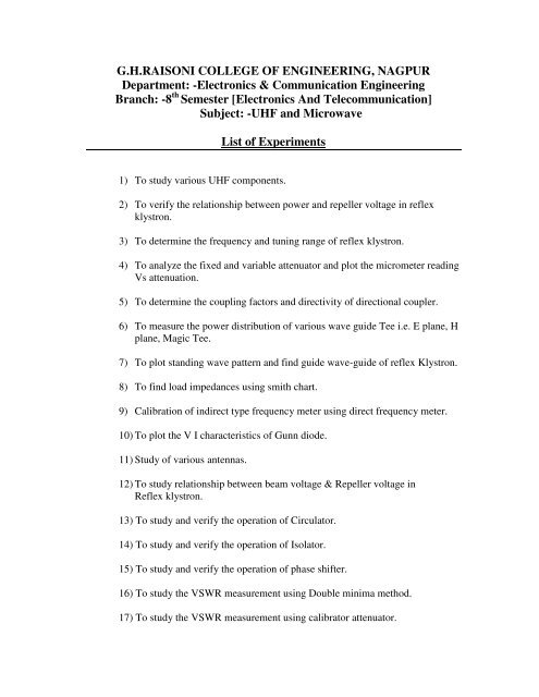
G.H.RAISONI COLLEGE OF ENGINEERING, NAGPUR<br />
Department: -<strong>Electronics</strong> & <strong>Communication</strong> <strong>Engineering</strong><br />
<strong>Branch</strong>: -8 th <strong>Semester</strong> [<strong>Electronics</strong> And Telecommunication]<br />
Subject: -UHF and Microwave<br />
List of Experiments<br />
1) To study various UHF components.<br />
2) To verify the relationship between power and repeller voltage in reflex<br />
klystron.<br />
3) To determine the frequency and tuning range of reflex klystron.<br />
4) To analyze the fixed and variable attenuator and plot the micrometer reading<br />
Vs attenuation.<br />
5) To determine the coupling factors and directivity of directional coupler.<br />
6) To measure the power distribution of various wave guide Tee i.e. E plane, H<br />
plane, Magic Tee.<br />
7) To plot standing wave pattern and find guide wave-guide of reflex Klystron.<br />
8) To find load impedances using smith chart.<br />
9) Calibration of indirect type frequency meter using direct frequency meter.<br />
10) To plot the V I characteristics of Gunn diode.<br />
11) Study of various antennas.<br />
12) To study relationship between beam voltage & Repeller voltage in<br />
Reflex klystron.<br />
13) To study and verify the operation of Circulator.<br />
14) To study and verify the operation of Isolator.<br />
15) To study and verify the operation of phase shifter.<br />
16) To study the VSWR measurement using Double minima method.<br />
17) To study the VSWR measurement using calibrator attenuator.
18) To studies variable attenuator & plot the micrometer reading vs.<br />
Attenuation.<br />
19) To measure the power distribution of Magic Tee
Experiment No 1<br />
Aim: - To study the various UHF components.<br />
List of Components:-<br />
1) Rectangular wave guide<br />
2) Circular wave guide<br />
3) Wave guide stand<br />
4) Flanges<br />
5) Fixed attenuator<br />
6) Micrometer type frequency meter<br />
7) Broad band tuned probe<br />
8) Wave guide matched detector mount<br />
9) Wave guide detector mount (tunable)<br />
10) Precision slide screw tuners<br />
11) Klystron mount<br />
12) Three port ferrite circulator<br />
13) E-H tuners<br />
14) H plane Tee<br />
15) E plane Tee<br />
16) Directional coupler<br />
17) Isolator<br />
18) Match termination<br />
19) Precision movable short<br />
20) Circular rectangular wave guide<br />
21) Load cell<br />
22) Horn antenna<br />
23) Sectoral horn antenna<br />
24) Pyramidal antenna<br />
25) Wave guide twist<br />
26) Liquid dielectric cell<br />
27) Solid dielectric cell<br />
28) Gunn oscillator<br />
29) PIN modulator<br />
30) Slotted section with probe carriage<br />
31) VSWR meter<br />
32) Klystron power supply<br />
33) Gunn power supply
Experiment no 2<br />
Aim: -To verify the relationship between power & repeller voltage in a reflex<br />
Klystron.<br />
Apparatus: -<br />
Reflex Klystron, Klystron power supply, Isolator, frequency meter, Variable attenuator,<br />
Detector mount, VSWR meter, BNC cable.<br />
Block Diagram:-<br />
Klystron<br />
power<br />
supply<br />
Klystron<br />
with<br />
Mount<br />
Theory: -<br />
Isolator<br />
Frequency<br />
meter<br />
Variable<br />
attenuator<br />
X band microwave bench set up<br />
Detector<br />
mount<br />
Multimeter<br />
V.S.W.R<br />
Meter<br />
Oscilloscope<br />
The reflex klystron makes use of velocity modulation to transform a continuous<br />
electron beam in to microwave power. Electron emitted from the cathode are<br />
accelerated and passed through the positive resonator toward negative reflector, which<br />
retard and finally reflects electron and electron return back through the resonator.<br />
Suppose hi field exist between the resonator. The electron traveling forward will be<br />
accelerated or retarded. As the voltage at the resonator change in amplitude, the<br />
accelerated electron leaves the resonator at the increased velocity and the retarded<br />
electron leave at the reduced velocity. The electrons leaving the resonator will need<br />
different time to return due to change in velocities. As a result returning electron group<br />
together in bunches. As the electron bunches pass through resonator they interact with<br />
voltage at resonator grids. If the bunches pass the grid at such time that the electrons are<br />
slowed down by the voltage energy will be delivered to the resonator and klystron will<br />
oscillate.
Modes- the transit time at reflex klystron is governed by repeller and anode voltages, so<br />
these should be carefully adjusted & regulated. First cavity is tuned to connect value of<br />
transit time from data supplied by manufacturer repeller voltages.<br />
Each area of graph represents voltage condition permitting oscillators for particular<br />
value of ‘n’.<br />
Uses: it is used as signal source in noise wave generator local oscillator in microwave<br />
receiver, stable oscillator in Radar receiver.<br />
Observation:-<br />
For mode I<br />
For mode II<br />
Procedure:-<br />
Beam voltage=<br />
Beam current=<br />
Repeller voltage =<br />
Sr.No. Repeller<br />
voltage (Volts)<br />
Sr.No. Repeller<br />
voltage (Volts)<br />
Power(dB)<br />
Power(dB)<br />
1) Connect the equipment & components as shown in the figure.<br />
2) Set the attenuator for max attenuation & set the arrange switch on the<br />
VSWR meter to 40-db positions.<br />
3) Set the mid selector switch of reflex klystron power supply to AM MOD<br />
position<br />
4) Beam voltage knob fully anticlockwise direction i.e. minimum position and also<br />
repeller voltage knob to minimum position.<br />
5) On the klystron power supply, set beam voltage to 250V. Limit the beam<br />
current to 20mA.. Now gradually rotate repeller voltage knob to obtaine<br />
deflection in VSWR meter.<br />
6) Find the frequency of oscillation by tuning frequency meter & observing dip in<br />
VSWR meter.<br />
7) Now change the repeller voltage & observe output power reading in db in<br />
VSWR meter.<br />
8) Plot graph between repeller voltage on x-axis &corresponding output on y-axis.
Result:- Plot power output for different modes as a function of repeller voltage.<br />
Questions:-<br />
1) What is reflex Klystron?<br />
2) What are disadvantages of reflex klystron?
Experiment No 3<br />
Aim: - To verify relationship between frequency of oscillation & repeller voltage of<br />
Reflex klystron.<br />
Apparatus:-<br />
Reflex Klystron, Klystron power supply, Isolator, frequency meter,<br />
Variable attenuator, Detector mount, VSWR meter, BNC cable.<br />
Block Diagram:-<br />
Theory:-<br />
Klystron<br />
power<br />
supply<br />
Klystron<br />
with<br />
Mount<br />
Isolator<br />
Frequency<br />
meter<br />
Variable<br />
attenuator<br />
X band microwave bench set up<br />
Detector<br />
mount<br />
Multimeter<br />
V.S.W.R<br />
Meter<br />
The reflex klystron makes use of velocity modulation to transform a continuous<br />
electron beam in to microwave power. Electron emitted from the cathode are<br />
accelerated and passed through the positive resonator toward negative reflector, which<br />
retard and finally reflects electron and electron return back through the resonator.<br />
Suppose hi field exist between the resonator. The electron traveling forward will be<br />
accelerated or retarded as the voltage at the resonator change in amplitude. The<br />
accelerated electron leaves the resonator at the increased velocity and the retarded<br />
electron leave at the reduced velocity. The electrons leaving the resonator will need<br />
different time to return due to change in velocities. As a result returning electron group<br />
together in bunches. As the electron bunches pass through resonator they interact with<br />
voltage at resonator grids. If the bunches pass the grid at such time that the electrons are<br />
slowed down by the voltage energy will be delivered to the resonator and klystron will<br />
oscillate.<br />
Oscilloscope
The frequency is preliminary determined by the dimension of resonant cavity. Hence by<br />
changing the volume of resonator, mechanical tuning range of klystron is possible. Also<br />
a small frequency change can be obtained by adjusting the reflector voltage. This is<br />
called electronic tuning.<br />
Observation:- Beam voltage=<br />
Beam current=<br />
Repeller voltage=<br />
For Mode I<br />
Procedure:-<br />
For Mode II<br />
Repeller<br />
voltage (Volts)<br />
Repeller<br />
voltage (Volts)<br />
Frequency<br />
(GHz)<br />
Frequency<br />
(GHz)<br />
1) Connect the equipment &component s as shown in the figure<br />
2) Set the variable attenuator to around zero position & set the range switch of<br />
VSWR meter to 40-db positions.<br />
3) Anti-clockwise direction, repeller voltage knob to minimum position.<br />
4) On the klystron power supply, VSWR meter &cooling fan. Set the beam voltage<br />
to 250v<br />
5) Gradually increase repeller voltage &look for sudden deflection in VSWR<br />
meter.<br />
6) Note the corresponding frequency with the help of frequency meter. Also note<br />
the repeller voltage.<br />
7) Slightly vary the repeller voltage on either side of this reading. Note the<br />
corresponding variation of the frequency.<br />
8) Find the tuning range after plotting the 3db points on the repeller voltage vs.<br />
power o/p graph.<br />
Result:- Find tuning range for two widely different repeller voltages.<br />
Questions:-<br />
1) What do you mean by higher mode?<br />
2) What are applications of klystrons?
Experiment no: 4<br />
Aim: -To verifies the fixed attenuator & plot the micrometer reading vs.<br />
Attenuation.<br />
Apparatus:-<br />
Reflex Klystron, Klystron power supply, Isolator, frequency meter,<br />
Variable & variable attenuator, Detector mount, VSWR meter, BNC<br />
Cable Matched load<br />
Block Diagram:-<br />
Klystron<br />
power<br />
supply<br />
Klystron<br />
with<br />
Mount<br />
Klystron<br />
power<br />
supply<br />
Microwa<br />
ve<br />
source<br />
Isolator Frequency<br />
meter<br />
Variable<br />
attenuator<br />
Attenuation of fixed and variable attenuator<br />
Isolator Frequency<br />
meter<br />
Variable<br />
attenuator<br />
Insertion loss and attenuation measurement of attenuator<br />
Slotted line Attenuator<br />
Slotted line<br />
V.S.W.R<br />
meter<br />
V.S.W.R<br />
meter<br />
Matched<br />
load<br />
Attenuator<br />
Matched<br />
load<br />
Detector<br />
mount
Theory:-<br />
The attenuator is a two port bidirectional device ,which attenuates some power in<br />
desired direction .<br />
Attenuation (A) =10 log (p1/p2)<br />
Where<br />
P1=power absorbed without attenuator.<br />
P2=power absorbed with attenuator.<br />
It consists of rectangular waveguide, which gives out the wave with resistive<br />
opposition. It is made up of Teflon and Polystyrene material. It opposes the power in<br />
desired direction.<br />
Fixed attenuation is defined as the ratio of power absorbed by the load with attenuation<br />
in the line. Attenuator used as variable attenuator. It is considerably reduced maxi<br />
attenuation .It is so because the electric intensity there is much lower for dominant<br />
mode .So they are made perpendicular to electric field place apart.<br />
Following characteristics of attenuators can be studied<br />
1) Input VSWR<br />
2) Insertion loss<br />
3) Amount of attenuation offered in to the lines<br />
4) Frequency sensitivity<br />
Observation:-<br />
Fixed attenuation O/p power<br />
(forward<br />
direction)<br />
Beam voltage =<br />
Beam current =<br />
Repeller voltage =<br />
Output Power( without attenuator) =<br />
O/p power<br />
(reverse direction)<br />
Average
Procedure:-<br />
Procedure for fixed attenuator: -<br />
1) Make a set up on.<br />
2) Set the Beam voltage between 250 to 300v limiting the beam current below 20<br />
mA.<br />
3) Obtained a mode at some value of repeller voltage by observing a sudden<br />
deflection in the VSWR meter.<br />
4) Adjust the reading of VSWR meter to 1db (in the range of 40 db) without fixed<br />
attenuator in the set up.<br />
5) Insert the fixed attenuator & note the reading on VSWR meter.<br />
6) Difference between reading with &without attenuator, gives the value of<br />
attenuation for the fixed attenuator.<br />
Procedure for variable attenuator:-<br />
1) Insert the variable attenuator.<br />
2) Observe micrometer reading & VSWR meter reading for different Settings of<br />
variable attenuator.<br />
3) Plot graph between the micrometer reading & VSWR meter reading in db.<br />
Result:- Value of attenuation<br />
1) Attenuator (3 dB) =<br />
2) Attenuator (6 dB) =<br />
3) Attenuator (9 dB) =<br />
Question:-<br />
1) What are types of attenuator?<br />
2) Where are different applications of attenuators?
Experiment No: 5<br />
Aim: -To find coupling factor & directivity of directional coupler.<br />
Apparatus:-<br />
Reflex Klystron, Klystron power supply, Isolator, frequency meter,<br />
Variable & variable attenuator, Detector mount, VSWR meter,<br />
BNC cable Matched load.<br />
Block Diagram:-<br />
Theory:-<br />
Microwave<br />
source<br />
Slotted<br />
line<br />
Isolator Variable<br />
Attenuator<br />
Probe<br />
M.H.D<br />
coupler<br />
M.H.D<br />
coupler<br />
Measurement of VSWR of M.H.D.coupler<br />
Frequenc<br />
y meter<br />
VSWR<br />
meter<br />
Matched load<br />
Matched load<br />
Matched load<br />
Matched load<br />
Directional coupler is a four-port device. Here power can be divided into almost in any<br />
ratio i.e. it samples energy flow in particular direction.<br />
It has a property that wave incident at port 1 coupler the power in 2 & 3 but not<br />
at port 4. Power incident at port 4 coupled with 3& 2 only met with 1, it means port 4 &<br />
1 are decoupled i.e. isolated port (S14=0). Similarly port 2 & 3 are also decoupled.<br />
It consists of two wave guide with a suitable coupling aperture located on<br />
common wall of wave guide. The distance between two apertures must be odd multiple<br />
of λg/4 .The performance &characteristics of directional coupler is determine by<br />
following parameter.
1) Coupling(C) = 10 log (pi/pf) db<br />
2) Directivity (D) = 10 log (pf/pb) db<br />
3) Isolation (I) =10 log (pi/pb) db<br />
4) Insertion loss (L) =10 log (pi/pt) db<br />
Main line insertion loss is the attenuation introduced in transmission line by insertion of<br />
coupler. It is defined as insertion<br />
Loss = 10 log 10P1/P2 When power is entered at port 1.<br />
Observation:-<br />
Procedure:<br />
Beam voltage =<br />
Beam current=<br />
Transmitted power=<br />
Forward power=<br />
Reverse power=<br />
Directivity=<br />
Coupling factor =<br />
Isolation loss =<br />
Insertion loss=<br />
1) Connect the set up as per the block dig .set mode selector switch to AM<br />
position.<br />
2) Adjust beam voltage between 250 to 300v.<br />
3) Set repeller voltage to any value between 50 to 100v<br />
4) Tune the set up to obtained max output on VSWR meter.<br />
5) Adjust the output to the reference level say 1 db.<br />
6) Insert the directional coupler just before the demodulator with Auxiliary arm<br />
(port 3) connected to detector. Port 2 should be terminated with matched load.<br />
Input to the coupler is at port 1.<br />
7) The demodulator output taken at port 3 of coupler is observed on VSWR meter.<br />
8) This power is called as forward power pf.<br />
9) Reverse the coupler & observe the output at port 3 while port 1 is terminated<br />
with matched load. This power is called as backward power Pb.<br />
10) The output of the set up without the coupler is called as pi.
Result:-<br />
Find coupling factor and directivity for two couplers<br />
Coupling factor =<br />
Directivity =<br />
Insertion loss =<br />
Question:-<br />
1) Define directional coupler.<br />
2) What are performance characteristics of directional coupler?
Experiment No: 6<br />
Aim: -To measure the power distribution of various magic Tee i.e. E plane, H plane.<br />
Apparatus:-<br />
Reflex Klystron, Klystron power supply, Isolator, frequency meter,<br />
Variable & variable attenuator, Detector mount, VSWR meter BNC<br />
Cable Matched load E plane, H plane & Magic Tee.<br />
Block Diagram: -<br />
Microwave<br />
source<br />
Theory:-<br />
Isolator Freque<br />
ncy<br />
meter<br />
Slotted<br />
line<br />
Detector<br />
mount<br />
Variable<br />
attenuator<br />
Study of Magic Tee<br />
VSWR<br />
meter<br />
Slotted<br />
line<br />
Wave-guide Tee’s are used for connecting a branch section of wave-guide in series or<br />
parallel with the main wave-guide. Tees are also be used as power divider field.<br />
1) Input VSWR- Value of SWR corresponding to each port as a load to the line while<br />
other ports are terminated in matched load.<br />
Tee<br />
Matched<br />
termination<br />
Matched<br />
termination<br />
Matched<br />
termination<br />
Tee<br />
2<br />
1<br />
Matched<br />
termination<br />
Matched<br />
termination<br />
Matched<br />
termination
2) Isolation- The isolation between E and H arm is defined as the ration of the power<br />
supplied by the generator connected to the E port 4 to the power detected at H arm port<br />
3 Isolation=10 log10P4/P3<br />
3) Coupling coefficient- It is defined as Cij=10 – /20<br />
Where is attenuation /isolation in dB when it is input arm and j is output arm<br />
Thus = 10 log Pi/Pj<br />
Where Pi is power delivered to arm i and Pj is power detected at j arm<br />
E plane Tee- Model 6031 E plane Tee is a type T junction & consist of 3 section wave<br />
guide joint together in order to divide & compare power levels .The signals entering<br />
first part of the Π junction will be equally divided at 2 nd 3 rd port of magnitude but<br />
opposite in direction.<br />
H plane Tee-Model 3065 H plane TEE are shunt type T-junction that is used in<br />
conjunction with VSWR meter, Frequency meter &other detector devices.<br />
Magic Tee – Model 3045 E-H consist of section of wave-guide with both series &<br />
shunt wave-guide are mounted at exact mid point of the main arm. This becomes four<br />
terminal devices where one terminal is isolated from the i/p. VSWR of 1.40 over +-<br />
15%freq range. This is achieved by inserting &connecting piece with stub.<br />
Procedure: -<br />
H-plane Tee: -<br />
a) Give i/p at port 1<br />
b) Observe o/p on VSWR meter at port 2&3.<br />
E plane Tee<br />
a) Give i/p at port 1.<br />
b) Observe output at port<br />
Magic Tee<br />
a) Give i/p at port 1.<br />
b) Observe the output at port 2,3&4<br />
c) Give i/p at port 4.<br />
d) Observe the o/p at port 1,2&3.<br />
Observation:-<br />
Beam voltage=<br />
Beam current=<br />
Repeller voltage=
a) H plane Tee<br />
1. Input at port 1=<br />
2. Output voltage<br />
At port 2=<br />
At port 3=<br />
b) E plane Tee<br />
1. Input at port 1=<br />
2. Output<br />
At port2=<br />
At port 3=<br />
Result: - Discuss the power distribution in each Tee.<br />
Question:-<br />
1) What are different types of Tee?<br />
3) What do you mean by ‘Magic’ Tee?
Experiment No: 7<br />
Aim: -To verify standing wave ratio using slotted line section.<br />
Apparatus:-<br />
Reflex Klystron ,Klystron power supply, Isolator, frequency meter, Variable & variable<br />
attenuator, Detector mount, VSWR meter, BNC cable Matched load E plane, H plane &<br />
Magic Tee.<br />
Block Diagram:-<br />
Klystron<br />
power<br />
supply<br />
Klystron<br />
mount<br />
Theory:-<br />
Isolator Frequency Variable<br />
meter attenuator<br />
VSWR<br />
meter<br />
Standing wave using slotted line section<br />
Slotted line<br />
section<br />
Slide screw<br />
tuner<br />
The electromagnetic field at any point of transmission line may be considered as the<br />
sum of two traveling waves. The ‘Incident wave’ propagates from generator and the<br />
reflected wave propagates toward the generator. The reflected wave is setup by<br />
reflection of incident wave from a discontinuity on the line or from the load impedance.<br />
The magnitude and phase of reflected wave depends upon amplitude and phase of the<br />
reflecting impedance. The presence of two traveling waves, gives rise to standing wave<br />
along with the line. The maximum field strength is found two waves are in phase and<br />
minimum where the two waves add in opposite phase. The distance between two<br />
successive minimums or maximum is half the guide wave- length on the line. The ratio<br />
of electrical field strength of reflected and incident wave is called reflection coefficient.<br />
The unknown device is connected to slotted line and SWR=S0 and position of one of<br />
the max is found. The device of the difference between min positions is used as<br />
reference position for reference position for impedance measurement. The unknown<br />
device is replaced by movable short now successive maximal positions are noted.<br />
Matched<br />
termination
Find the difference between min position and max position obtained due to continuous<br />
load slotted line section consist of precision mechanism section of wave guide in which<br />
small longitudinal slot has been cut which is basic means of non tearing. A built probe<br />
has a scale with vernier reading of a form 0.01 cm.<br />
The voltage standing wave Ratio (VSWR) is defined as ratio between maximum and<br />
minimum field strength along the line.<br />
Hence VSWR S = Emax/Emin<br />
= (|Ei| + |Er|) / (|Ei| - |Er|)<br />
Reflection Coefficient P = Er / Ei = (Z - Z0) / (Z + Z0)<br />
Where Z is the impedance at a point on line. Z0 is characteristic impedance.<br />
The above equation gives following equations.<br />
Observation:-<br />
|e| = (s-1) / (s+1)<br />
Main scale reading Venier scale<br />
reading<br />
Procedure: -<br />
Beam voltage= 236 V<br />
Beam current= 13 mA<br />
Repeller voltage= 5V<br />
Total reading Power (db)<br />
1) First Switch on the supply<br />
2) Tune the bench<br />
3) Move the slotted line section slowly so that SWR meter reading is minimum<br />
4) Now take the reading of VSWR for different position<br />
5) Plot the graph between VSWR and distance.<br />
Result:- Thus, standing waves in wave guide is plotted and theoretical practical<br />
value of guide wavelength are found.<br />
Question:-<br />
1) What do you mean by standing wave ratio?<br />
2) Which meter we used to measure standing wave?
Experiment No: 8<br />
Aim: - To find load impedances using smith chart.<br />
Apparatus:-<br />
Reflex Klystron, Klystron power supply, Isolator, frequency meter,<br />
Variable & variable attenuator, Detector mount, VSWR meter,<br />
BNC cable Matched load E plane, H plane & Magic Tee.<br />
Block Diagram:-<br />
Klystron<br />
power supply<br />
2K25<br />
Klystron<br />
mount<br />
Theory: -<br />
Isolator<br />
Frequency<br />
meter<br />
Variable<br />
Attenuator<br />
Set up for Impedance measurement<br />
The impedance at any point of a transmission line can be written in the form R + jX.<br />
For comparison SWR can be calculated as,<br />
S = (1 + |R|) / (1 - |R|)<br />
Probe<br />
Slotted<br />
line<br />
V.S.W.R<br />
meter<br />
S. S.<br />
Tuner<br />
Movable<br />
short<br />
Where c = (Z/Zo + 1) / (Z/Zo – 1)<br />
Z is the impedance at any point. The measurement is performed in following way.<br />
The unknown device is connected to the slotted line and the SWR = so and the position<br />
of one minima is determined. Then unknown device is replaced by movable short to<br />
the slotted line. Two successive minima positions are noted. The twice of the<br />
difference between minima position will be guide wavelength. One of the minima is<br />
used as reference for impedance measurement. Find the difference of reference minima<br />
and minima position obtained form unknown load. Let it be‘d’. Take a smith chart<br />
‘taking ‘1’ as center, draw a circle of radius equal to so. Mark a point on circumference<br />
Matched<br />
terminator<br />
r
of chart towards load side at a distance equal (to-d)/λ. Join the center with this point.<br />
Find the point where it cut the drawn circle. The co-ordination of this point will show<br />
the normalized impedance of load.<br />
Procedure: -<br />
1) Connect the component and equipment as shown in the diagram<br />
2) Set the modulation switch of the klystron power supply to CW position. Beam<br />
voltage control knob should be kept at mini. Repeller voltage knob should be at<br />
mini.<br />
3) On the klystron power supply.<br />
4) Gradually increase the beam voltage up to 250v Limiting the beam current<br />
below 20mA.<br />
5) Keep the direct frequency meter completely open &adjust the attenuator to<br />
obtained current of 1 mA at the o/p<br />
6) Move the plunger of indirect frequency meter to obtain adapt in ammeter<br />
7) Note the micrometer reading on the direct frequency meter &observe the<br />
corresponding frequency on the direct frequency meter.<br />
8) Repeat steps 5, 6&7 after changing the setting of frequency on the direct<br />
frequency meter.<br />
9) Plot the graph between frequency µmeter readings.<br />
.<br />
Observation:-<br />
Beam voltage=<br />
Beam current=<br />
Repeller voltage=<br />
Repeller voltage Current (mA) Micrometer<br />
readings<br />
Result:- The calculated load impedance is =<br />
Question:-<br />
1) What are various application of smith chart?<br />
2) How to measure load impedance using smith chart?<br />
Frequency from<br />
calibration chart
Experiment No: 9<br />
Aim: - Calibration of indirect type frequency meter using direct frequency meter.<br />
Apparatus:-<br />
Reflex Klystron, Klystron power supply, Isolator, frequency meter,<br />
Variable & variable attenuator, Detector mount, VSWR meter,<br />
BNC cable Matched load E plane, H plane & Magic Tee.<br />
Block Diagram:-<br />
Klystron<br />
power<br />
supply<br />
Klystron<br />
with<br />
Mount<br />
Theory:-<br />
Isolator<br />
Frequency<br />
meter<br />
Variable<br />
attenuator<br />
X band microwave bench set up<br />
Detector<br />
mount<br />
Basically there are two types of frequency meter available in our lab. They are Direct<br />
frequency meter and indirect frequency meter.<br />
Direct frequency meter – In direct frequency meter we get direct reading as by simple<br />
observation basically we are aligning horizontal line on the vertical line and particular<br />
obtained in between two horizontal lines is required frequency.<br />
Indirect frequency meter – Here in these we are measuring frequency indirectly that<br />
is we are required to calculate least count of frequency meter and corresponding<br />
frequency we will get by measuring both the main scale reading and variable scale<br />
reading along with the least count.<br />
The impedance at any point of transmission line can be calculated as<br />
Multimeter<br />
V.S.W.R<br />
Meter<br />
Oscilloscop<br />
e
S=1-P1 /1-P2, C= (Z/Z0-1)/Z/Z0<br />
The unknown device is connected to slotted line and SWR=S0 and position of one of<br />
the max is found. The device of the difference between min positions is used as<br />
reference position for reference position for impedance measurement. The unknown<br />
device is replaced by movable short now successive maximal positions are noted.<br />
Find the difference between min position and max position obtained<br />
due to continuous load slotted line section consist of precision mechanism section of<br />
wave guide in which small longitudinal slot has been cut which is basic means of non<br />
tearing. A built probe has a scale with venire reading of a form 0.01 cm least counts and<br />
can be mounted easily if precision readings are required<br />
Procedure: -<br />
1) Tune the test bench<br />
2) Note down the max & min VSWR values by changing slotted line section<br />
distance<br />
Observation:-<br />
Calculate power by Pmax & Pmin:-<br />
Pmax=<br />
Pmin=<br />
R=<br />
F=<br />
λ=<br />
Beam voltage=<br />
Beam current=<br />
Repeller voltage=<br />
Result: - Discuss the power distribution in each Tee.<br />
Question:-<br />
1) Which type of frequency meter is convenient to use?<br />
2) How we can measure direct frequency meter?
Experiment No: 10<br />
Aim: - Study of Gunn diode and plot VI characteristics of Gunn diode.<br />
Apparatus:-<br />
Reflex Klystron, Klystron power supply, Isolator, frequency meter,<br />
Variable & variable attenuator, Detector mount, VSWR meter, BNC<br />
Cable Matched load E plane, H plane & Magic Tee.<br />
Block Diagram:-<br />
Klystron<br />
power<br />
supply<br />
Gunn<br />
diode<br />
Theory:-<br />
Isolator PIN<br />
modulator<br />
CRO<br />
Frequency<br />
meter<br />
Set for study of a gunn oscillator<br />
Variable<br />
attenuator<br />
VSWR<br />
meter<br />
Detector<br />
The Gunn oscillator is based on negative differential conductivity effect in bulk<br />
semiconductors which has two conduction band minima separated by an energy gap .A<br />
disturbance at cathode gives rise to high field region which travel’s towards the anode<br />
.When this high field domains reaches the anode, it disappears and another domain is<br />
formed at the cathode and starts moving anode and so on. The time required for domain<br />
to travel from cathode to anode gives oscillation frequency.<br />
A uniform type of uniform type of Gunn diode with same contact as the end surface.<br />
Above some critical voltage current becomes function of time .It was discovered by J B<br />
Gunn. It uses bulk property of semiconductor only. So it must be associated with<br />
electron rather than holes .The voltage applied is proportional to the sample length and<br />
hence electric field is expressed in v/m.<br />
When DC voltage is applied across the side of Gunn diode, cadmium ferrite in -ve<br />
resistance property across at particular voltage range value .As the applied potential<br />
increases i.e. greater than electric field higher electron present, hence higher current<br />
across the line in short time so acceleration occur in microwave range. Actually
Frequency of oscillation in determined the time so acceleration occurs in microwave<br />
range. Actually frequency of oscillation is determined the time that the bunches of<br />
electron form and arrive at the end.<br />
Procedure: -<br />
1) Switch on the Gunn power supply.<br />
2) Adjust the bench to get maximum o/p waveform<br />
3) By making voltage initially zero note down the current.<br />
Observation:-<br />
Beam voltage =<br />
Beam current =<br />
Repeller voltage =<br />
Voltage (volt) Current (mA)<br />
Result:- Thus the VI characteristics of Gunn diode is studied.<br />
Question:-<br />
1) How Gunn diode is different from other diode?<br />
2) What are different applications of Gunn diode?
Aim: -To study the various antennas.<br />
Block Diagram:-<br />
Gunn<br />
power<br />
supply<br />
Gunn<br />
oscillator<br />
Theory:-<br />
Isolator<br />
V.S.W.R.<br />
Meter<br />
Experiment No: 11<br />
Pin<br />
modulator<br />
Detector<br />
Variable<br />
attenuator<br />
Set up for antenna measurement<br />
Frequency<br />
meter<br />
Antennas are used at all frequency but in actual practice the frequency on which it<br />
operates depends on its shape to the large extent . Antenna types are<br />
1) Horn antenna- A horn antenna may be regarded as a flared out or open out<br />
wave guide A wave guide is capable of radiating in to open space provided the<br />
same is excited at one end and open at other end. However the radiation is much<br />
greater through wave-guide than the two-wire transmission the line in waveguide<br />
is small in portion of incident wave is radiated and large portion is<br />
reflected back by the open circuit.<br />
2) Parabolic reflector or microwave dish- A parabola is a two-dimensional plane<br />
curve .A practical reflector is a three dimensional curved surface. Therefore<br />
rotating a parabola about its axis .The surface so generated is called as<br />
“Parabolic” Which is also called as “Microwave Dish or Parabolic Reflector”<br />
forms practical reflector. Parabolic produces a parallel beam of circular cross<br />
section because the mouth of parabolic is circular.
3) Hertz antenna- It is also a half wave dipole antenna .The dipole antenna dates<br />
back to the early half RF experiments in the center so that RF power can be<br />
applied to it .One can think of the half wave dipoles an open circuited<br />
transmission line that has been spread out so that the transmission line that has<br />
been spread out so that transmission can be spread out in space .A dipole can be<br />
of any length commonly is just under ½ wavelength long.<br />
L=486/F<br />
F=Frequency<br />
L= length<br />
Result:- Thus the different antennas are studied.<br />
Question:-<br />
1) What are different types of antennas?<br />
2) What do you mean by microwave dish?
Experiment no 12<br />
Aim: - To study relationship between beam voltage & Repeller voltage in<br />
Reflex klystron.<br />
Apparatus:-<br />
Reflex Klystron, Klystron power supply, Isolator, frequency meter,<br />
Variable attenuator, Detector mount, VSWR meter, BNC cable.<br />
Block diagram:-<br />
Theory:-<br />
X band microwave bench set up<br />
In Reflex klystron oscillation are obtained only for particular combination of Vo & Vr<br />
which gives desired transient time. The each shaded area correspond to oscillation at a<br />
particular transit time mode between 1(3/4) to 4(3/4) cycles and each value of n is said<br />
to be different modes in a reflex klystron .The earlier the mode the larger will be the<br />
amount of power which is advantages but it require higher voltage so lower efficiency<br />
and also increase the insulation problem.<br />
If the frequency of oscillation change appreciably the pattern still has the same general<br />
characteristic but location of the region of oscillation of the region of oscillation are<br />
shifted because of the fact that with a new frequency different transit time in second is<br />
required to give same transit time in cycle.<br />
Observation:-<br />
Klystron<br />
power<br />
supply<br />
Klystron<br />
with<br />
mount<br />
Isolator<br />
Frequen<br />
cy meter<br />
Variable<br />
attenuator<br />
Beam voltage Repeller voltage<br />
VSWR<br />
meter<br />
Detector<br />
mount
Procedure:-<br />
1. Connect the equipment &component s as shown in the figure<br />
2. Set the variable attenuator to around zero position & set the range switch of<br />
VSWR meter to 40-db positions.<br />
3. Set the mid selector switch to AM –MOD position, beam voltage knob fully<br />
anti-clockwise direction, repeller voltage knob to minimum position.<br />
4. On the klystron power supply, VSWR meter &cooling fan .Set limiting beam<br />
current to less than 16 mA<br />
5. Gradually increase beam voltage &look for sudden variation in repeller voltage<br />
6. Note the corresponding voltage with the help of meter. Also note the repeller<br />
voltage.<br />
7. Slightly vary the repeller voltage on either side of this reading. Note the<br />
corresponding variation of the repeller voltage.<br />
Result:-<br />
Study relationship between beam voltage & repeller voltage in reflex klystron.<br />
Viva Questions :-<br />
1) What is the nature of the graph between repeller voltage and the beam voltage?<br />
2) What do you mean by optimum bunching?
Experiment no 13<br />
Aim: - To study and verify the operation of Circulator.<br />
Apparatus:- Reflex Klystron ,Klystron power supply ,circulator ,Isolator ,frequency<br />
meter, Variable attenuator Detector mount ,VSWR meter ,BNC cable.<br />
Block diagram:-<br />
VSWR<br />
meter<br />
Theory:-<br />
Klystron<br />
power<br />
supply<br />
Detector<br />
Klystron<br />
mount<br />
Circulator<br />
Klystron<br />
oscillator<br />
Slide<br />
screw<br />
tuner<br />
Isolator<br />
X band microwave bench set up<br />
Variable<br />
attenuator<br />
Frequenc<br />
y meter<br />
Fixed<br />
attenuator<br />
It is a multipart microwave junction device providing one way sequential transmission<br />
of power between the ports .It has a property that terminal is connected to next<br />
clockwise terminal depending upon the direction of wave-guide. Following the<br />
different ways to construct a circulator.<br />
1) Circulator using faradays rotation isolator.<br />
2) Using two magic Tee and Gyrator.<br />
3) Using 2 side hole and 3db coupler, 2 non reciprocal &1 reciprocal phase shifter<br />
.<br />
Two additional ports 3&4 place the construction of faradays circulator using isolator<br />
without twist except the resistive card 1&2 respectively. Port 3 is a rectangular wave
guide fastened in perpendicular to the circular wave guide near port 1 such that the<br />
narrow dimension of port 3 is parallel to the broad dimension of port 1 ie port 3 is<br />
perpendicular to port 1 similarly every time.<br />
Observation:-<br />
1. Input power at port 1= 36 dB<br />
Output power<br />
At port 2=<br />
2. Input power at port 2= 40 dB<br />
Output power<br />
At port 3=<br />
3. Input power at port 3= 44 dB<br />
Output power<br />
At port 4=<br />
4. Input power at port 4= 48 dB<br />
Output power<br />
At port 1=<br />
Procedure:-<br />
Circulator:-<br />
a) Give i/p at port 1<br />
b) Observe o/p on VSWR meter at port 2.<br />
c) Give i/p at port 2<br />
d) Observe o/p on VSWR meter at port 3.<br />
e) Give i/p at port 3<br />
f) Observe o/p on VSWR meter at port 4<br />
g) Give i/p at port 4<br />
h) Observe o/p on VSWR meter at port 1.<br />
Result:- Find out path followed by the Circulator.<br />
Viva Question :-<br />
1) What is the basic concept of Circulator?<br />
2) What are the different type of Circulator?
Experiment no 14<br />
Aim: - To study and verify the operation of Isolator.<br />
Apparatus:- Reflex Klystron ,Klystron power supply ,Isolator ,frequency meter,<br />
Variable attenuator, Detector mount ,VSWR meter ,BNC cable.<br />
Block diagram:-<br />
Theory:-<br />
Klystron<br />
power<br />
supply<br />
VSWR<br />
meter<br />
Klystron<br />
mount<br />
Detector<br />
Klystron<br />
oscillator<br />
Slide<br />
screw<br />
tuner<br />
Isolator<br />
X band microwave bench set up<br />
Variable<br />
attenuato<br />
r<br />
Frequenc<br />
y meter<br />
Fixed<br />
attenuato<br />
r<br />
It is a two port device where wave propagate from one port to second with out any<br />
attenuation and when wave moves in back direction there will be maximum attenuation<br />
therefore it is a online device. Isolator is mostly used to couple microwave generator to<br />
load so with these arrangement efficiency of reflex klystron will increase and also avoid<br />
the damage of microwave source generator due to the reflected wave because of<br />
mismatching at the output load .Its construction is very much similar to Gyrator except<br />
uses a 45 degree twist and 45 degree rotation in addition to these two thin resistive card
are inserted in the input and output wave guide parallel to the broader wall of wave<br />
guide<br />
If the wave will not fully absorbed by resistive card 1 then reflection taking places<br />
move toward port 2 which is absorbed by the resistive card at port 2 .<br />
Observation:-<br />
1) Input power at port 1=<br />
Output power<br />
At port 2=<br />
2) Input power at port 2=<br />
Output power<br />
At port 1=<br />
Procedure:-<br />
1) Give i/p at port 1<br />
2) Observe o/p on VSWR meter at port 2.<br />
3) Give i/p at port 2<br />
4) Observe o/p on VSWR meter at port 1.<br />
Result:- Find path followed by the isolator .<br />
Viva Questions :-<br />
1. What is the basic concept of Isolator?<br />
2. What are the different types of Isolator?
Experiment no 15<br />
Aim: - To study and verify the operation of phase shifter.<br />
Apparatus:- Reflex Klystron, Klystron power supply, Isolator, phase shifter,<br />
frequency meter, Variable attenuator, Detector mount, VSWR meter, and BNC cable.<br />
Block diagram:-<br />
VSWR<br />
meter<br />
Theory:-<br />
Klystron<br />
power<br />
supply<br />
Detector<br />
Klystron<br />
mount<br />
Phase<br />
shifter<br />
Klystron<br />
oscillator<br />
Slide<br />
screw<br />
tuner<br />
Isolator<br />
X band microwave bench set up<br />
Variable<br />
attenuator<br />
Frequenc<br />
y meter<br />
Fixed<br />
attenuator<br />
Gyrator is also called as phase shifter is two port microwave device introduce by Hogel.<br />
It also act as a non reciprocal phase shifter which gives the phase shift of 180 degree for<br />
the transmission from port 2 to 1 .It also uses the property of faradays rotation.<br />
It consist of a rectangular wave guide with a 90 degree twist connected to circular wave<br />
guide with which carries a cylindrical ferrite rod with the end tapered to reduce the<br />
reflection from it and a static magnetic field Bo is applied along the axis to produce the<br />
90 degree faradays rotation of TE11 dominant mode in circular wave guide When the<br />
wave propagate form 1 to 2 in the direction when it passes through the twist the plane<br />
of polarization by rotates by 90 degree clockwise direction. The total angle of rotation
is 180 degree. When wave travel in the reverse direction from port 2 to 1 the faradays<br />
rotation is unchanged.<br />
Observation:-<br />
1) Input power at port 1=<br />
Output power<br />
At port 2=<br />
2) Input power at port 2=<br />
Output power<br />
At port 1=<br />
Procedure:-<br />
1) Give I /P at port 1<br />
2) Observe o/p on VSWR meter at port 2.<br />
3) Give I /P at port 2<br />
4) Observe o/p on VSWR meter at port 1.<br />
Result:- Find path followed by the Phase shifter.<br />
Viva Question: -<br />
1) What do you mean by gyrator?<br />
2) What are the applications of gyrator?
Experiment no 16<br />
Aim: - To study the VSWR measurement using Double minima method.<br />
Apparatus:- Reflex Klystron, Klystron power supply, Isolator, phase shifter,<br />
frequency meter, Variable attenuator, Detector mount, VSWR meter, and BNC cable.<br />
Block diagram:-<br />
Theory:-<br />
Klystron<br />
power<br />
supply<br />
VSWR<br />
meter<br />
Klystron<br />
mount<br />
Detector<br />
Klystron<br />
oscillator<br />
Slide<br />
screw<br />
tuner<br />
Isolator<br />
X band microwave bench set up<br />
Variable<br />
attenuator<br />
Frequenc<br />
y meter<br />
Fixed<br />
attenuator<br />
The direct measurement of minima for high VSWR causes over loading of detector To<br />
avoided these double minima method are used.<br />
A load having the high VSWR form the standing wave pattern in such a manner that<br />
minima point will not define and hence detector does not obey the square law .These<br />
method is used to measure high VSWR measurement<br />
The voltage standing wave Ratio (VSWR) is defined as ratio between maximum and<br />
minimum field strength along the line.<br />
Hence VSWRS S = Emax/Emin
= (|Ei| + |Er|) / (|Ei| - |Er|)<br />
Reflection Coefficient P = Er / Ei = (Z - Z0) / (Z + Z0)<br />
Where Z is the impedance at a point on line. Z0 is characteristic impedance. The above<br />
equation gives following equations.<br />
|e| = (s-1) / (s+1)<br />
The unknown device is connected to slotted line and SWR=S0 and position of one of<br />
the max is found. The device of the difference between min positions is used as<br />
reference position for reference position for impedance measurement. The unknown<br />
device is replaced by movable short now successive maximal positions are noted.<br />
Observation:-<br />
Measure distance d1=<br />
Measure distance d2=<br />
Measure distance∆d =<br />
Measure distance λg=<br />
Procedure:-<br />
1) Set the depth of the tunner, then slightly move then λg/4.<br />
2) Move the probe along the slotted line until minima is indicated.<br />
3) Adjust the VSWR gain control knob or attenuator to obtained the reading of 30<br />
db of a normal dB scale (0 to 10 dB) on VSWR meter.<br />
4) Move the probe to the left of the slotted line until full scale deflection is<br />
obtained (o dB on 0 to 10 dB scale) note & record the probe position on the<br />
meter<br />
5) Repeat the step 3&4 and then move the probe right to the slotted line until fullscale<br />
deflection is obtained Note the reading of probe position let it be d2.<br />
6) The distance between (d2-d1) is ∆d.<br />
7) Replace the slide screw tuner by movable short.<br />
8) Move the probe position and measure the distance between two successive<br />
minima position of the probe is equal to the λg/42. Twice this distance gives the<br />
wavelength λg.<br />
9) The VSWR is given by<br />
VSWR=λg/Π∆d.<br />
Result:-Get the value and calculate VSWR power.<br />
Viva Question :-<br />
1) What do you mean by VSWR?<br />
2) What is the different method of VSWR power measurement?
Experiment no 17<br />
Aim: - To study the VSWR measurement using calibrator attenuator.<br />
Apparatus:- Reflex Klystron, Klystron power supply, Isolator, phase shifter,<br />
frequency meter, Variable attenuator, Detector mount, VSWR meter, and BNC cable.<br />
Block diagram:-<br />
VSW<br />
R<br />
meter<br />
Theory:-<br />
Klystron<br />
power<br />
supply<br />
Detector<br />
Klystron<br />
mount<br />
Slotted<br />
section<br />
Klystron<br />
oscillator<br />
Slide<br />
screw<br />
tuner<br />
Isolator<br />
X band microwave bench set up<br />
Variable<br />
attenuator<br />
Frequenc<br />
y meter<br />
Fixed<br />
attenuator<br />
The magnitude and phase of reflected wave depends upon amplitude and phase of the<br />
reflecting impedance. The presence of two traveling waves, gives rise to standing wave<br />
along with the line. The maximum field strength is found two waves are in phase and<br />
minimum where the two waves adds in opposite phase. The distance bet two<br />
successive minimum or maximum is half the guide wave- length on the line. The ratio<br />
of electrical field strength of reflected and incident wave is called reflection coefficient.<br />
Standing wave are created along the length of the transmission line due to mismatch<br />
between characteristic impudence ZL.
The actual voltage v on the line at any point is the sum of Vi+Vr of the voltage of<br />
incident &reflected wave at the point .This result in the voltage distribution of the line<br />
is called as the standing wave pattern<br />
In the particular line both the waves are present voltage maximal occurs at the point<br />
where the two waves are in the same phase and minima the point where two wave are<br />
in the same phase where the difference between maxima and the minima are more<br />
pronounce larger.<br />
Observation:-<br />
Procedure:-<br />
Vmax=<br />
Vmin=<br />
A2(dB)=20 log(Vmax)=<br />
A1(dB)=20 log(Vmin)=<br />
A2-A1=<br />
1) Keep the attenuator to the minimum position.<br />
2) On the klystron power supply, VSWR meter and cooling fan<br />
3) Turn the meter switch of power supply to the beam voltage position set Vo<br />
to 300v with tuning the same switch note down corresponding beam current<br />
order of the 20 to 30 mA.<br />
4) Turn the same meter switch of power supply to Vr position and get the<br />
oscillation in the VSWR meter<br />
5) Move the probe with slotted to get the maximum deflection in VSWR meter<br />
and note down the attenuator reading move the probe to minima position<br />
read the VSWR on the scale and record it move the probe carriage along the<br />
slotted line for maxima position and the change the attenuation so that<br />
indication in the VSWR meter is same .<br />
6) Move the probe of slotted section to the minima position and with changing<br />
the attenuator reading bring the VSWR deflection to the maxima .Note<br />
down the attenuator reading i.e. nothing but as the VSWR.<br />
A2(dB)=20 log(Vmax)<br />
A1(dB)=20 log(Vmin)<br />
Result:-Get the value and calculate VSWR power.<br />
Viva Question:-<br />
1) What do you mean by Calibrator VSWR?<br />
2) What is the range of high VSWR power measurement?
Experiment no: 18<br />
Aim: -To studies variable attenuator & plot the micrometer reading vs.<br />
Attenuation.<br />
Apparatus:- Reflex Klystron ,Klystron power supply ,Isolator ,frequency meter,<br />
Variable & variable attenuator, Detector mount, VSWR meter, BNC cable Matched<br />
load.<br />
Block diagram:-<br />
Klystron<br />
power<br />
supply<br />
Klystron<br />
with<br />
mount<br />
Theory:-<br />
Isolator Variable<br />
attenuator<br />
Direct<br />
reading<br />
frequency<br />
Attenuation of fixed and variable attenuator<br />
VSWR<br />
meter<br />
Detector<br />
mount<br />
Fixed<br />
attenuator<br />
The variable attenuator resistive card mounted inside the wave guide with its surface<br />
parallel to magnetic field .The electromagnetic field varies over the cross section of a<br />
wave guide and it is strongest at the center of the broad wall .The Vane can be moved<br />
laterally from center of the wave guide towards the narrow wall. Where the attenuation<br />
is considerably reduced .The resistive card changes the intensity near the narrow wall<br />
the resistive wire tapered over the either side of over the length of λg to minimize the<br />
reflection from itself to reduce type reflection from mounting rod ,which are parallel to<br />
the electromagnetic field used or place.<br />
There are various advantages of flap type of attenuator such as support of resistive card<br />
is very simple, no of ports of support are extended in to wave guide.
Observation:-<br />
Procedure:-<br />
Beam voltage=<br />
Beam current=<br />
Repeller voltage=<br />
Least Count =<br />
Micrometer scale<br />
reading<br />
O/p power (db)<br />
Procedure for variable attenuator:-<br />
3) Insert the variable attenuator.<br />
4) Observed micrometer reading & VSWR meter reading for different<br />
Settings of variable attenuator.<br />
5) Plot graph between the micrometer reading & VSWR meter reading in<br />
db.<br />
Result:- Value of attenuator<br />
1) Attenuator 1<br />
2) Attenuator 2<br />
Viva Question: -<br />
1) What do you mean by Flap type of attenuator?<br />
2) What are the different application of attenuator?
VSWR<br />
meter<br />
Experiment no: 19<br />
Aim: - To measure the power distribution of Magic Tee<br />
Apparatus:- Reflex Klystron ,Klystron power supply ,Isolator ,frequency meter,<br />
Variable & variable attenuator, Detector mount, VSWR meter ,BNC cable Matched<br />
load ,Magic Tee.<br />
Block diagram:-<br />
Theory:-<br />
Klystron<br />
power<br />
supply<br />
Detector<br />
Klystron<br />
mount<br />
Magic<br />
Tee<br />
Klystron<br />
oscillator<br />
Slide<br />
screw<br />
tuner<br />
Isolator<br />
Variable<br />
attenuato<br />
r<br />
Frequenc<br />
y meter<br />
Fixed<br />
attenuato<br />
r<br />
Magic Tee has the property that when the power is fed from port1 it will appear at port<br />
2 &3 only equal in magnitude &in phase but in the port 4.similarly power fed from port<br />
4 is coupled equally in to port 2&3 only equal in magnitude & opposite in phase but not<br />
coupled to port 4 similarly power fed from the port 3 is coupled equally in port 1&4 but<br />
not into port 2.<br />
It is used in microwave impedance measuring bridge, as a antenna duplexer ,as a<br />
balanced microwave mixer in the super heterodyne microwave receiver ,also used as a<br />
balance phase detector it detect the relative phase of the two signal .<br />
Magic Tee – Model 3045 E-H consists of section of wave-guide with both series &<br />
shunt wave-guide are mounted at exact mid point of the main arm. This becomes four<br />
terminal devices where one terminal is isolated from the i/p. VSWR of 1.40 over +-<br />
15%freq range. This is achieved by inserting &connecting piece with stub.
Observation:-<br />
Magic Tee<br />
Procedure:-<br />
1. Input power at port 1=<br />
2. Output power<br />
At port 2=<br />
At port 3=<br />
At port 4=<br />
3. Input power at port 1=<br />
4. Output power<br />
At port 1=<br />
At port 2=<br />
At port 3=<br />
Magic Tee<br />
a) Give i/p at port 1.<br />
b) Observe the output at port 2,3&4<br />
c) Give i/p at port 4.<br />
d) Observe the output at port 1,2 & 3<br />
Result:- Discuss the power distribution in Magic Tee.<br />
Viva Question: -<br />
1) State Carlins theorem.<br />
2) What do you understand by scattering matrix of magic Tee?


