Interview with Laurent Desclos - EEWeb
Interview with Laurent Desclos - EEWeb
Interview with Laurent Desclos - EEWeb

You also want an ePaper? Increase the reach of your titles
YUMPU automatically turns print PDFs into web optimized ePapers that Google loves.
TECHNICAL ARTICLE<br />
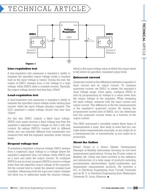
SMU1<br />
Source V<br />
Measure I<br />
Figure 1<br />
Line-regulation test<br />
A line-regulation test measures a regulator’s ability to<br />
maintain the specified output voltage under a constant<br />
load as the input voltage is varied. During this test, the<br />
output of SMU1 sweeps from a low voltage to a high<br />
voltage, while SMU2 sinks a constant current. Typically,<br />
the output voltage should vary less than 100mV.<br />
Load-regulation test<br />
A load-regulation test measures a regulator’s ability to<br />
maintain the specified output voltage under varying load<br />
current, while the input voltage remains constant. The<br />
LDO regulator’s output voltage should vary less than<br />
100mV.<br />
For this test, SMU1 outputs a fixed input voltage.<br />
SMU2 once again sources a fixed voltage less than the<br />
regulator’s expected output voltage so that it will sink<br />
current. By setting SMU2’s current limit to different<br />
levels, you can simulate different load magnitudes and<br />
measure how well the regulator operates under varying<br />
loads.<br />
Dropout voltage test<br />
C IN<br />
In Out<br />
Voltage<br />
Regulator<br />
GND<br />
To measure a regulator’s dropout-voltage, SMU1 sweeps<br />
from a maximum input voltage to a voltage below the<br />
regulator’s expected drop out voltage, while SMU2 acts<br />
as a load and sinks the output current. To configure<br />
SMU2 to act as a load, program SMU2 to source a voltage<br />
lower than the expected output voltage of the regulator.<br />
Set the current limit to create the desired constant load<br />
condition. Measuring both the input and output voltages<br />
will allow you to determine easily the dropout voltage,<br />
which is the input voltage value at which the output starts<br />
to fall below its specified, regulated output level.<br />
Quiescent current<br />
Quiescent current is the difference between a regulator’s<br />
input current and its output current. To measure<br />
quiescent current, set SMU1 to sweep the regulator’s<br />
input voltage range. Once again, configure SMU2 to<br />
sink by programming its voltage to a value lower than<br />
the output voltage of the regulator. While sweeping<br />
the input voltage, measure both the input current and<br />
output current. The difference in the two measurements<br />
is the regulator’s quiescent current. By varying the<br />
programmed current limit of SMU2, you can determine<br />
how the quiescent current varies as a function of the<br />
output current.<br />
The SMU instrument’s versatility makes these types of<br />
measurements a snap. Also keep in mind that you can<br />
make these measurements manually, as you might do in<br />
a development lab, or automatically, as you might do in<br />
production.<br />
About the Author<br />
SMU2<br />
Source V<br />
Measure I<br />
Robert Green is a Senior Market Development<br />
Manager at Keithley Instruments focusing on low level<br />
measurement applications. During his 20-year career at<br />
Keithley, Mr. Green has been involved in the definition<br />
and introduction of a wide range of products including<br />
picoammeters, electrometers, digital multimeters, and<br />
temperature measurement products. He received a<br />
B.S. in Electrical Engineering from Cornell University<br />
and an M. S. in Electrical Engineering from Washington<br />
University, St. Louis, Missouri. ■<br />
<strong>EEWeb</strong> | Electrical Engineering Community Visit www.eeweb.com 20<br />
C OUT<br />
A A<br />
TECHNICAL ARTICLE