Implementing an ADC with a Microcontroller, an Op Amp ... - EEWeb
Implementing an ADC with a Microcontroller, an Op Amp ... - EEWeb
Implementing an ADC with a Microcontroller, an Op Amp ... - EEWeb

Create successful ePaper yourself
Turn your PDF publications into a flip-book with our unique Google optimized e-Paper software.
Maxim > Design Support > Technical Documents > Application Notes > A/D <strong>an</strong>d D/A Conversion/Sampling Circuits > APP 5074<br />
Maxim > Design Support > Technical Documents > Application Notes > <strong>Microcontroller</strong>s > APP 5074<br />
Keywords: adc, dac, <strong>an</strong>alog to digital, digital to <strong>an</strong>alog, microcontroller, op amp, uC<br />
May 11, 2012<br />
APPLICATION NOTE 5074<br />
<strong>Implementing</strong> <strong>an</strong> <strong>ADC</strong> <strong>with</strong> a <strong>Microcontroller</strong>, <strong>an</strong> <strong>Op</strong><br />
<strong>Amp</strong>, <strong>an</strong>d Resistors<br />
By: Gordon Lee<br />
May 11, 2012<br />
Abstract: This design idea explains how to implement <strong>an</strong> 8-bit <strong>an</strong>alog-to-digital converter (<strong>ADC</strong>), using a microcontroller<br />
<strong>an</strong>d some common components.<br />
Analog-to-digital converters (<strong>ADC</strong>s) are used in a wide r<strong>an</strong>ge of electronic devices. However, most of the low-cost<br />
microcontrollers do not include <strong>an</strong> <strong>ADC</strong> peripheral. This design idea provides a way to implement <strong>an</strong> 8-bit <strong>ADC</strong> using a<br />
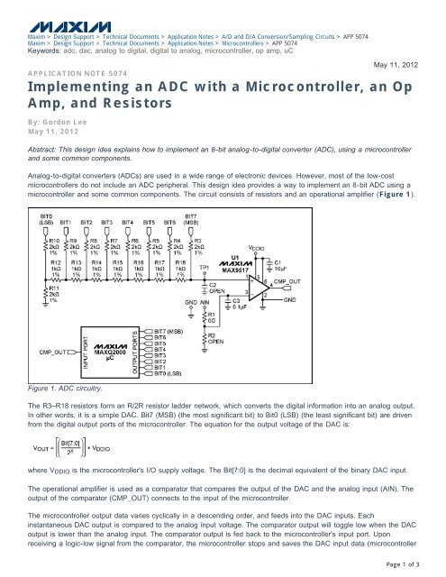
microcontroller <strong>an</strong>d some common components. The circuit consists of resistors <strong>an</strong>d <strong>an</strong> operational amplifier (Figure 1).<br />
Figure 1. <strong>ADC</strong> circuitry.<br />
The R3–R18 resistors form <strong>an</strong> R/2R resistor ladder network, which converts the digital information into <strong>an</strong> <strong>an</strong>alog output.<br />
In other words, it is a simple DAC. Bit7 (MSB) (the most signific<strong>an</strong>t bit) to Bit0 (LSB) (the least signific<strong>an</strong>t bit) are driven<br />
from the digital output ports of the microcontroller. The equation for the output voltage of the DAC is:<br />
where VDDIO is the microcontroller's I/O supply voltage. The Bit[7:0] is the decimal equivalent of the binary DAC input.<br />
The operational amplifier is used as a comparator that compares the output of the DAC <strong>an</strong>d the <strong>an</strong>alog input (AIN). The<br />
output of the comparator (CMP_OUT) connects to the input of the microcontroller.<br />
The microcontroller output data varies cyclically in a descending order, <strong>an</strong>d feeds into the DAC inputs. Each<br />
inst<strong>an</strong>t<strong>an</strong>eous DAC output is compared to the <strong>an</strong>alog input voltage. The comparator output will toggle low when the DAC<br />
output is lower th<strong>an</strong> the <strong>an</strong>alog input. The comparator output is fed back to the microcontroller's input port. Upon<br />
receiving a logic-low signal from the comparator, the microcontroller stops <strong>an</strong>d saves the DAC input data (microcontroller<br />
Page 1 of 3
output data). This final DAC input data is the <strong>ADC</strong> output.<br />
Listing 1 provides sample code written for Maxim's MAXQ2000 microcontroller.<br />
#include "bitb<strong>an</strong>ging_iomaxq200x.h"<br />
void main(void)<br />
{<br />
int wait;<br />
char DAC_out;<br />
PD0=0xFF; //Sets IO port 0 to output (This port shows the <strong>ADC</strong> result)<br />
PD3=0xFF; //Sets IO port 3 to output (This port connects to the DAC input)<br />
PD6_bit.bit2=0; //Sets IO port 6, pin 2, to input<br />
//This pin connects to the output of the comparator<br />
while(1)<br />
{<br />
//Set DAC output to the MAX (DAC output = 3.3v) at the beginning<br />
//Then decrease the DAC output 1 LSB at a time,<br />
//until the output of the comparator toggles low<br />
for(DAC_out=0xFF; DAC_out>=0; DAC_out--)<br />
{<br />
PO3=DAC_out; //Sets the value of the output port 3 to DAC_out<br />
}<br />
}<br />
}<br />
//wait for the output of the comparator to settle<br />
for(wait=0; wait
For Technical Support: http://www.maxim-ic.com/support<br />
For Samples: http://www.maxim-ic.com/samples<br />
Other Questions <strong>an</strong>d Comments: http://www.maxim-ic.com/contact<br />
Application Note 5074: http://www.maxim-ic.com/<strong>an</strong>5074<br />
APPLICATION NOTE 5074, AN5074, AN 5074, APP5074, Appnote5074, Appnote 5074<br />
Copyright © by Maxim Integrated Products<br />
Additional Legal Notices: http://www.maxim-ic.com/legal<br />
Page 3 of 3