DigiFOX Quick Guide Ver 3.1 - Schneider Optics
DigiFOX Quick Guide Ver 3.1 - Schneider Optics
DigiFOX Quick Guide Ver 3.1 - Schneider Optics

You also want an ePaper? Increase the reach of your titles
YUMPU automatically turns print PDFs into web optimized ePapers that Google loves.
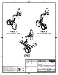
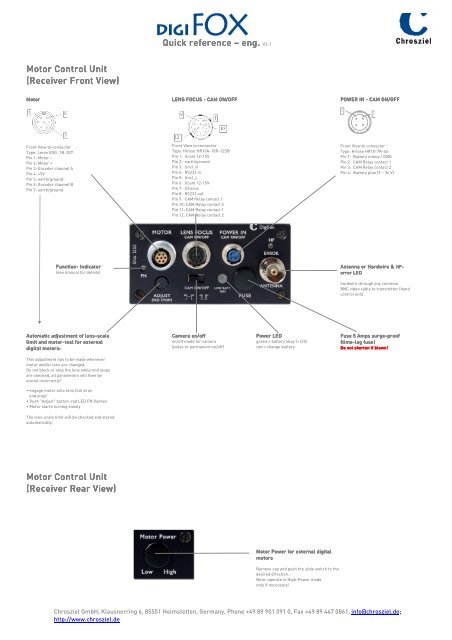
Motor Motor Control Control Unit<br />
Unit<br />
(Receiver (Receiver Front Front View)<br />
View)<br />
Motor<br />
Motor<br />
Front View to connector<br />
Type: Lemo EGG. 1B. 307<br />
Pin 1: Motor –<br />
Pin 2: Motor +<br />
Pin 3: Encoder channel A<br />
Pin 4: +5V<br />
Pin 5: earth/ground<br />
Pin 6: Encoder channel B<br />
Pin 7: earth/ground<br />
Function Function- Function Indicator<br />
(see manual for details)<br />
Automatic Automatic adjustment adjustment of of lens lens-scale<br />
lens scale<br />
limit limit and and motor motor-test motor test test for external<br />
digital digital motors:<br />
motors:<br />
This adjustment has to be made whenever<br />
motor and/or lens are changed.<br />
Do not block or stop the lens while end stops<br />
are checked, all parameters will then be<br />
stored incorrectly!<br />
• engage motor onto lens (not at an<br />
end stop)<br />
• Push "Adjust" button, red LED FN flashes<br />
• Motor starts turning slowly<br />
The lens-scale limit will be checked and stored<br />
automatically.<br />
Motor Motor Control Control Control Unit Unit<br />
Unit<br />
(Receiver (Receiver (Receiver Rear Rear Rear View)<br />
View)<br />
<strong>Quick</strong> <strong>Quick</strong> <strong>Quick</strong> reference reference – eng.<br />
eng.<br />
LENS LENS FOCUS FOCUS - CAM ON/OFF<br />
Front View to connector<br />
Type: Hirose HR10A-10R-12SB<br />
Pin 1: Ucam 12-15V<br />
Pin 2: earth/ground<br />
Pin 3: Uref_H<br />
Pin 4: RS232 in<br />
Pin 5: Uref_L<br />
Pin 6: Ucam 12-15V<br />
Pin 7: UFocus<br />
Pin 8: RS232 out<br />
Pin 9: CAM Relay contact 1<br />
Pin 10: CAM Relay contact 2<br />
Pin 11: CAM Relay contact 1<br />
Pin 12: CAM Relay contact 2<br />
Camera Camera on/off<br />
on/off<br />
on/off mode for camera<br />
(pulse or permanent on/off)<br />
eng. V<strong>3.1</strong><br />
Power Power LED<br />
LED<br />
green = battery okay (>12V)<br />
red = change battery<br />
Motor Motor Power Power for for external external digital<br />
digital<br />
motors<br />
motors<br />
Remove cap and push the slide switch to the<br />
desired direction.<br />
Note: operate in High-Power mode<br />
only if necessary!<br />
POWER POWER IN IN IN - CAM ON/OFF ON/OFF<br />
Antenna Antenna or or Hardwire Hardwire Hardwire & & & HF HF- HF<br />
error error LED LED<br />
LED<br />
hardwire through any common<br />
BNC video cable to transmitter (hand<br />
control unit).<br />
Fuse Fuse 5 5 Amps Amps surge surge-proof<br />
surge proof proof<br />
(time (time-lag (time lag fuse fuse) fuse<br />
Do Do not not short shorten short shorten<br />
en if if if blown!<br />
blown!<br />
Chrosziel GmbH, Klausnerring 6, 85551 Heimstetten, Germany, Phone +49 89 901 091 0, Fax +49 89 447 0861, info@chrosziel.de;<br />
http://www.chrosziel.de<br />
4<br />
Front View to connector<br />
Type: Hirose HR10-7R-4S<br />
Pin 1: Battery minus / GND<br />
Pin 2: CAM Relay contact 1<br />
Pin 3: CAM Relay contact 2<br />
Pin 4: Battery plus (9 – 36 V)<br />
1