UPGRADING REPAIRING PCs
UPGRADING REPAIRING PCs
UPGRADING REPAIRING PCs

Create successful ePaper yourself
Turn your PDF publications into a flip-book with our unique Google optimized e-Paper software.
<strong>UPGRADING</strong><br />
AND<br />
<strong>REPAIRING</strong> <strong>PCs</strong><br />
TECHNICIAN’S PORTABLE<br />
REFERENCE<br />
SECOND EDITION<br />
Scott Mueller and Mark Edward Soper
Upgrading and Repairing <strong>PCs</strong><br />
Technician’s Portable Reference,<br />
Second Edition<br />
Copyright© 2001 by Que<br />
All rights reserved. No part of this book shall be reproduced, stored<br />
in a retrieval system, or transmitted by any means, electronic,<br />
mechanical, photocopying, recording, or otherwise, without written<br />
permission from the publisher. No patent liability is assumed<br />
with respect to the use of the information contained herein.<br />
Although every precaution has been taken in the preparation of<br />
this book, the publisher and authors assume no responsibility for<br />
errors or omissions. Neither is any liability assumed for damages<br />
resulting from the use of the information contained herein.<br />
International Standard Book Number: 0-7897-2454-5<br />
Library of Congress Catalog Card Number: 00-104012<br />
Printed in the United States of America<br />
First Printing: October 2000<br />
02 01 00 4 3 2 1<br />
Trademarks<br />
All terms mentioned in this book that are known to be trademarks<br />
or service marks have been appropriately capitalized. Que cannot<br />
attest to the accuracy of this information. Use of a term in this<br />
book should not be regarded as affecting the validity of any trademark<br />
or service mark.<br />
Warning and Disclaimer<br />
Every effort has been made to make this book as complete and<br />
accurate as possible, but no warranty or fitness is implied. The<br />
information provided is on an as is basis. The authors and the publisher<br />
shall have neither liability nor responsibility to any person or<br />
entity with respect to any loss or damages arising from the information<br />
contained in this book.
Associate Publisher<br />
Greg Wiegand<br />
Senior Acquisitions Editor<br />
Jill Byus Schorr<br />
Senior Development Editor<br />
Rick Kughen<br />
Managing Editor<br />
Thomas F. Hayes<br />
Project Editor<br />
Karen S. Shields<br />
Copy Editor<br />
Megan Wade<br />
Technical Editor<br />
Mark Reddin<br />
Proofreader<br />
Jeanne Clark<br />
Indexer<br />
Mary SeRine<br />
Interior Design<br />
Kevin Spear<br />
Cover Design<br />
Karen Ruggles<br />
Layout Technicians<br />
Heather Hiatt Miller<br />
Stacey Richwine-DeRome<br />
iii
Contents at a Glance<br />
1 General Technical Reference 1<br />
2 System Components and Configuration 19<br />
3 BIOS Configurations and Upgrades 69<br />
4 SCSI and IDE Hard Drives and Optical Drives 93<br />
5 Floppy, Removable, Tape, and Flash Memory Storage 143<br />
6 Serial Ports and Modems 165<br />
7 Parallel Ports, Printers, Scanners, and Drives 189<br />
8 USB and IEEE-1394 Ports and Devices 205<br />
9 Keyboards, Mice, and Input Devices 215<br />
10 Video and Audio 237<br />
11 Networking 271<br />
12 Operating System Installation and Diagnostic Testing 299<br />
13 Tools and Techniques 309<br />
14 Connector Quick Reference 317<br />
Index 329
Contents<br />
1 General Technical Reference 1<br />
PC Subsystem Components Quick Reference 1<br />
The Motherboard and Its Components 2<br />
Understanding Bits, Nibbles, and Bytes 3<br />
Standard Capacity Abbreviations and Meanings 3<br />
Glossary of Essential Terms 5<br />
PC99 Color Standards 10<br />
Hexadecimal/ASCII Conversions 10<br />
2 System Components and Configuration 19<br />
Processors and Their Data Bus Widths 19<br />
Differences Between PC/XT and AT Systems 20<br />
Intel and Compatible Processor Specifications 21<br />
Troubleshooting Processor Problems 27<br />
Motherboard Form Factors 29<br />
Baby-AT Motherboard 30<br />
LPX Motherboard 31<br />
ATX Motherboard 31<br />
NLX Motherboard 32<br />
Which Motherboard Is Which? 32<br />
PC99 Color-Coding for Ports 33<br />
Power Supplies 34<br />
LPX Versus ATX Power Supplies 34<br />
Power Connectors for the Drive(s) 36<br />
Quick-Reference Chart for Troubleshooting Power<br />
Supplies 37<br />
Memory Types 38<br />
30-Pin SIMM 39<br />
72-Pin SIMM 39<br />
DIMMs 40<br />
RDRAM 40<br />
DDR SDRAM 41<br />
Parity Versus Non-Parity Memory 42<br />
Requirements for ECC Memory Use 43<br />
Using the Divide by 3 Rule to Determine Parity<br />
Support 43<br />
Using the Divide by 9 Rule to Determine Parity<br />
Support 43<br />
Expanding Memory on a System 44<br />
Memory Troubleshooting 45<br />
Memory Usage Within the System 46<br />
Hardware and Firmware Devices That Use Memory<br />
Addresses 46<br />
Using Memory Addresses Beyond 1MB (0FFFFF) 49<br />
Determining Memory Address Ranges in Use 49
vi<br />
Contents<br />
Other Add-On Card Configuration Issues 50<br />
IRQs 50<br />
DMA 52<br />
Determining Actual IRQ and DMA Usage 52<br />
I/O Port Addresses 54<br />
Determining Actual I/O Address Ranges in Use 57<br />
Troubleshooting Add-on Card Resource Conflicts 57<br />
Expansion Slots 62<br />
ISA 62<br />
EISA—A 32-bit Version of ISA 62<br />
VL-Bus—A Faster 32-Bit Version of ISA 62<br />
PCI 66<br />
AGP 66<br />
3 BIOS Configurations and Upgrades 69<br />
What the BIOS Is and What It Does 69<br />
When a BIOS Update Is Necessary 69<br />
Specific Tests to Determine Whether Your BIOS Needs<br />
an Update 70<br />
Fixing BIOS Limitations—BIOS Fixes and Alternatives<br />
70<br />
How BIOS Updates Are Performed 71<br />
Where BIOS Updates Come From 71<br />
Precautions to Take Before Updating a BIOS 72<br />
How to Recover from a Failed BIOS Update Procedure 73<br />
Plug-and-Play BIOS 74<br />
PnP BIOS Configuration Options 75<br />
When to Use the PnP BIOS Configuration Options 77<br />
Other BIOS Troubleshooting Tips 77<br />
Soft BIOS CPU Speed and Multiplier Settings 78<br />
Determining Which BIOS You Have 79<br />
Determining the Motherboard Manufacturer for BIOS<br />
Upgrades 79<br />
Identifying Motherboards with AMI BIOS 79<br />
Identifying Motherboards with Award BIOS 81<br />
Identifying Motherboards with Phoenix or Microid<br />
Research BIOS 82<br />
Accessing the BIOS Setup Programs 82<br />
How the BIOS Reports Errors 83<br />
BIOS Beep Codes and Their Purposes 83<br />
AMI BIOS Beep Codes 84<br />
Award BIOS Beep Codes 84<br />
Phoenix BIOS Beep Codes 85<br />
IBM BIOS Beep and Alphanumeric Error Codes 85<br />
Microid Research Beep Codes 86<br />
Reading BIOS Error Codes 88<br />
Onscreen Error Messages 88<br />
Interpreting Error Codes and Messages 88<br />
BIOS Configuration Worksheet 89<br />
4 SCSI and IDE Hard Drives and Optical Drives 93<br />
Understanding Hard Disk Terminology 93<br />
Heads, Sectors per Track, and Cylinders 93<br />
Hard Drive Heads 93<br />
Sectors per Track 93<br />
Cylinders 94
Contents vii<br />
IDE Hard Drive Identification 94<br />
Master and Slave Drives 95<br />
Breaking the 504MB (528-Million-Byte) Drive Barrier 97<br />
Using LBA Mode 98<br />
When LBA Mode Is Necessary—and When Not to Use<br />
It 98<br />
Problems with LBA Support in the BIOS 99<br />
Dangers of Altering Translation Settings 99<br />
Detecting Lack of LBA Mode Support in Your System<br />
100<br />
Using FDISK to Determine Compatibility Problems<br />
Between the Hard Disk and BIOS 101<br />
Getting LBA and Extended Int13h Support for Your<br />
System 102<br />
Determining Whether Your System Supports Extended<br />
Int13h 103<br />
Drive Capacity Issues in Microsoft Windows 95 and 98<br />
104<br />
Sources for BIOS Upgrades and Alternatives for Large IDE<br />
Hard Disk Support 105<br />
Standard and Alternative Jumper Settings 106<br />
Improving Hard Disk Speed 107<br />
Ultra DMA 108<br />
UDMA/66 and UDMA/100 Issues 108<br />
Bus-Mastering Chipsets for IDE 109<br />
Benefits of Manual Drive Typing 111<br />
Troubleshooting IDE Installation 112<br />
SCSI 113<br />
SCSI Types and Data Transfer Rates 113<br />
Single-Ended Versus Differential SCSI 114<br />
Low-Voltage Differential Devices 114<br />
Recognizing SCSI Interface Cables and Connectors 115<br />
8-Bit SCSI Centronics 50-Pin Connector 115<br />
SCSI-2 High-Density Connector 115<br />
SCSI-3 68-Pin P Cable 116<br />
RAID Array, Hot Swappable 80-Pin Connector 116<br />
SCSI Drive and Device Configuration 117<br />
SCSI Device ID 117<br />
SCSI Termination 119<br />
SCSI Configuration Troubleshooting 120<br />
Hard Disk Preparation 124<br />
Using FDISK 125<br />
Drive-Letter Size Limits 125<br />
Large Hard Disk Support 125<br />
Benefits of Hard Disk Partitioning 126<br />
FAT-32 Versus FAT-16 Cluster Sizes 127<br />
Converting FAT-16 Partition to FAT-32 128<br />
NTFS Considerations and Default Cluster Sizes 128<br />
How FDISK and the Operating System Create and Allocate<br />
Drive Letters 129<br />
Assigning Drive Letters with FDISK 130<br />
High-Level (DOS) Format 132<br />
Replacing an Existing Drive 133<br />
Drive Migration for MS-DOS Users 133<br />
Drive Migration for Windows 9x/Me Users 134<br />
XCOPY32 for Windows 9x Data Transfer 134
viii<br />
Contents<br />
Hard Disk Drive Troubleshooting and Repair 135<br />
Optical Drive Interface Types 137<br />
MS-DOS Command-Line Access to CD-ROM Drives for<br />
Reloading Windows 137<br />
Troubleshooting Optical Drives 138<br />
Failure Reading a CD 138<br />
Failure Reading CD-R and CD-RW Disks in a CD-ROM<br />
or DVD Drive 139<br />
IDE/ATAPI CD-ROM Drive Runs Slowly 139<br />
Trouble Using Bootable CDs 140<br />
5 Floppy, Removable, Tape, and Flash Memory<br />
Storage 143<br />
Floppy Drives 143<br />
Where Floppy Drives Fail—and Simple Fixes 144<br />
The Drive Cover 144<br />
The Stepper Motor 144<br />
Interface Circuit Boards 145<br />
Read/Write Heads 145<br />
Floppy Drive Hardware Resources 145<br />
Don’t Use a Floppy Drive While Running a Tape<br />
Backup 146<br />
Disk Drive Power and Data Connectors 146<br />
Floppy Drive Troubleshooting 148<br />
Common Floppy Drive Error Messages—Causes and<br />
Solutions 149<br />
Removable Storage Drives 150<br />
Sources for “Orphan” Drive Media, Repairs, Drivers,<br />
and Support 153<br />
Emergency Access to Iomega Zip Drive Files in Case of<br />
Disaster 153<br />
Troubleshooting Removable Media Drives 154<br />
Types of Flash Memory Devices 155<br />
Tape Backup Drives and Media 155<br />
Common Tape Backup Standards 155<br />
Travan Tape Drives and Media 156<br />
Proprietary Versions of Travan Technology 157<br />
Getting Extra Capacity with Verbatim QIC-EX Tape<br />
Media 157<br />
OnStream ADR Tape Drives and Media 158<br />
Choosing the Best High-Performance Backup<br />
Technology 159<br />
Successful Tape Backup and Restore Procedures 160<br />
Tape Drive Troubleshooting 161<br />
Tape Retensioning 164<br />
6 Serial Ports and Modems 165<br />
Understanding Serial Ports 165<br />
Pinouts for Serial Ports 166<br />
Current Loop Serial Devices and 25-Pin Serial Ports<br />
168<br />
UARTs 169<br />
UART Types 169<br />
Identifying Your System UART 170<br />
High-Speed Serial Ports (ESP and Super ESP) 171<br />
Upgrading the UART Chip 171
Serial Port Configuration 172<br />
Avoiding Conflicts with Serial Ports 173<br />
Troubleshooting I/O Ports in Windows 9x and Me 173<br />
Advanced Diagnostics Using Loopback Testing 174<br />
Loopback Plug Pinouts—Serial Ports 175<br />
Modems 176<br />
Modems and Serial Ports 176<br />
Modem Modulation Standards 176<br />
56Kbps Standards 177<br />
Upgrading from x2 or K56flex to V.90 with Flash<br />
Upgrades 178<br />
External Versus Internal Modems 180<br />
Modem Troubleshooting 180<br />
Pinouts for External Modem Cable (9-Pin at PC) 184<br />
Win98SE, Windows 2000, Windows Me, and ICS 184<br />
Requirements for ICS 185<br />
Overview of the Configuration Process 185<br />
7 Parallel Ports, Printers, Scanners, and Drives 189<br />
Parallel Port Connectors 189<br />
Parallel Port Performance 190<br />
Parallel Port Configurations 191<br />
Testing Parallel Ports 191<br />
Troubleshooting Parallel Ports 192<br />
Printers 193<br />
Hewlett-Packard PCL Versions 194<br />
Comparing Host-Based to PDL-Based Printers 195<br />
Printer Hardware Problems 196<br />
Printer Connection Problems 199<br />
Printer Driver and Application Problems 201<br />
Troubleshooting Parallel Port and Other Types of Scanners 202<br />
Parallel Port Drives 203<br />
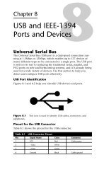
8 USB and IEEE-1394 Ports and Devices 205<br />
Universal Serial Bus 205<br />
USB Port Identification 205<br />
Pinout for the USB Connector 205<br />
Typical USB Port Locations 206<br />
Adding USB Ports to Your Computer 206<br />
Prerequisites for Using USB Ports and Peripherals 207<br />
Troubleshooting USB Ports 207<br />
Using USB Hubs with Legacy (Serial, Parallel, and PS/2)<br />
Ports 209<br />
Online Sources for Additional USB Support 209<br />
USB 2.0 209<br />
IEEE-1394 210<br />
Adding IEEE-1394 Ports to Your Computer 210<br />
Comparing USB and IEEE-1394 211<br />
Troubleshooting IEEE-1394 Host Adapters and Devices<br />
212<br />
IEEE-1394 and Linux 213<br />
Online Sources for Additional IEEE-1394 Support 213<br />
9 Keyboards, Mice, and Input Devices 215<br />
Keyboard Designs 215<br />
The 101-Key Enhanced Keyboard 215<br />
101-Key Versus 102-Key Keyboards 215<br />
The 104-Key Windows Keyboard 215<br />
Contents ix
x<br />
Contents<br />
Using Windows Keys 215<br />
Keyboard-Only Commands for Windows<br />
9x/NT4/2000/Me with Any Keyboard 216<br />
Standard Versus Portable Keyboards 219<br />
Keyswitch Types 219<br />
Cleaning a Foam-Element Keyswitch 220<br />
Adjusting Keyboard Parameters in Windows 221<br />
Keyboard Layouts and Scan Codes 221<br />
Keyboard Connectors 225<br />
Keyboard Connector Signals 226<br />
USB Keyboard Requirements 227<br />
Keyboard Troubleshooting and Repair 227<br />
Keyboard Connector Voltage and Signal Specifications 229<br />
Keyboard Error Codes 229<br />
Mice and Pointing Devices 230<br />
Mouse Motion Detection Methods 230<br />
Pointing Device Interface Types 230<br />
Wireless Mouse Types 231<br />
Software Drivers for the Mouse 231<br />
Alternative Pointing Devices 232<br />
Mouse Troubleshooting 233<br />
10 Video and Audio 237<br />
Selecting a Monitor Size 237<br />
Monitor Resolution 238<br />
CRTs Versus LCDs 238<br />
Common Monitor Resolutions 238<br />
LCD Versus CRT Display Size 239<br />
Monitor Power Management Modes 239<br />
VGA Video Connector Pinouts 241<br />
VGA DB-15 Analog Connector Pinout 241<br />
Digital Flat Panel Pinouts 242<br />
Digital Visual Interface Pinouts 243<br />
VGA Video Display Modes 244<br />
Video RAM 246<br />
Memory, Resolution, and Color Depth 247<br />
Determining the Amount of RAM on Your Display Card 249<br />
Local-Bus Video Standards 249<br />
RAMDAC 251<br />
Refresh Rates 252<br />
Adjusting the Refresh Rate of the Video Card 252<br />
Comparing Video Cards with the Same Chipset 253<br />
Setting Up Multiple Monitor Support in Windows<br />
98/Me/2000 253<br />
System Configuration Issues for Multiple-Monitor<br />
Support 256<br />
Video Card and Chipset Makers Model Reference 256<br />
3-D Chipsets 256<br />
Multimedia Devices 256<br />
Troubleshooting Video Capture Devices 257<br />
Testing a Monitor with Common Applications 258<br />
Audio I/O Connectors 260<br />
Connectors for Advanced Features 262
Contents xi<br />
Sound Quality Standards 263<br />
Configuring Sound Cards 263<br />
PCI Versus ISA Sound Cards 264<br />
Multifunction (Modem and Sound) Cards 264<br />
Troubleshooting Audio Hardware 265<br />
Hardware (Resource) Conflicts 265<br />
Detecting Resource Conflicts 265<br />
Most Common Causes of Hardware Conflicts with<br />
Sound Card 266<br />
Freeing Up IRQ 5 for Sound Card Use While Still<br />
Printing 267<br />
Other Sound Card Problems 267<br />
11 Networking 271<br />
Client/Server Versus Peer-to-Peer Networking 271<br />
Choosing Network Hardware and Software 272<br />
NIC 272<br />
UTP Cable 273<br />
Hub 273<br />
Software 273<br />
Network Protocols 275<br />
IP and TCP/IP 275<br />
Selecting a Network Data-Link Protocol (Specification) 276<br />
Network Cable Connectors 277<br />
Wire Pairing for Twisted-Pair Cabling 278<br />
Making Your Own UTP Cables 278<br />
Network Cabling Distance Limitations 280<br />
Cabling Standards for Fast Ethernet 281<br />
Specialized Network Options 281<br />
What About Home Networking? 281<br />
Wireless Networking Standards 282<br />
Wireless Network Configuration and Selection Issues<br />
284<br />
TCP/IP Network Protocol Settings 284<br />
TCP/IP Protocol Worksheet 285<br />
Troubleshooting Networks 287<br />
Troubleshooting Network Software Setup 287<br />
Troubleshooting Networks in Use 288<br />
Troubleshooting TCP/IP 289<br />
Direct Cable Connections 290<br />
Null Modem and Parallel Data-Transfer Cables 290<br />
Direct Connect Software 291<br />
Troubleshooting Direct Cable Connections 295<br />
12 Operating System Installation and Diagnostic<br />
Testing 299<br />
Installing an Operating System on an Empty Drive 299<br />
Installing MS-DOS 299<br />
Installing Windows 9x 300<br />
Installing Windows Me 300<br />
Installing Windows NT 4.0 or Windows 2000 301<br />
Upgrading an Operating System 302<br />
Installing to the Same Folder 302<br />
Installing to a Different Folder 302<br />
Installing to a Different Partition 302
xii<br />
Contents<br />
Checking for IRQ, DMA, I/O, and Memory Usage 302<br />
MS-DOS Using MSD 302<br />
Windows 9x/2000/Me 303<br />
Windows NT 4.0 304<br />
Software Toolkit 304<br />
13 Tools and Techniques 309<br />
General Information 309<br />
Hardware Tools and Their Uses 309<br />
Tools of the Trade—Drive Installation 310<br />
Tools of the Trade—Motherboard and Expansion Card<br />
Installation 311<br />
Tools of the Trade—External Device and Networking<br />
Installation 312<br />
Tools of the Trade—Data Transfer 313<br />
Tools of the Trade—Cleaning and Maintenance 314<br />
14 Connector Quick Reference 317<br />
Serial Ports and Cables 317<br />
Parallel Ports 318<br />
SCSI Ports 318<br />
USB and IEEE-1394 (FireWire) 319<br />
Video Connectors 321<br />
Video Ports 321<br />
Video Cables 322<br />
Sound Card Ports 323<br />
Sound Card External Ports 323<br />
Sound Card Internal Connectors 325<br />
Network and Modem Ports and Cables 325<br />
RJ-45 Port and Cable 325<br />
RJ-11 Port and Cable Connector 326<br />
Older Network Connectors 326<br />
Index 329
About the Authors<br />
Scott Mueller is president of Mueller Technical Research, an international<br />
research and corporate training firm. Since 1982, MTR has<br />
specialized in the industry’s longest running, most in-depth, accurate,<br />
and effective corporate PC hardware and technical training<br />
seminars, maintaining a client list that includes Fortune 500 companies,<br />
the U.S. and foreign governments, and major software and<br />
hardware corporations, as well as PC enthusiasts and entrepreneurs.<br />
His seminars have been presented to thousands of PC support professionals<br />
throughout the world.<br />
Scott Mueller has developed and presented training courses in all<br />
areas of PC hardware and software. He is an expert in PC hardware,<br />
operating systems, and data-recovery techniques. For more information<br />
about a custom PC hardware or data-recovery training seminar<br />
for your organization, contact Lynn at<br />
Mueller Technical Research<br />
21 Spring Lane<br />
Barrington Hills, IL 60010-9009<br />
Phone: (847) 854-6794<br />
Fax: (847) 854-6795<br />
Internet: scottmueller@compuserve.com<br />
Web: http://www.m-tr.com<br />
Scott has many popular books, articles, and course materials to his<br />
credit, including Upgrading and Repairing <strong>PCs</strong>, which has sold more<br />
than 2 million copies, making it by far the most popular PC hardware<br />
book on the market today.<br />
If you have questions about PC hardware, suggestions for the next<br />
edition of the book, or any comments in general, send them to<br />
Scott via email at scottmueller@compuserve.com.<br />
When he is not working on PC-related books or teaching seminars,<br />
Scott can usually be found in the garage working on performance<br />
projects. This year a Harley Road King with a Twin-Cam 95ci Stage<br />
III engine continues as the main project (it’s amazing how something<br />
with only two wheels can consume so much time and money<br />
), along with a modified 5.7L ‘94 Impala SS and a 5.9L Grand<br />
Cherokee (hotrod SUV).
Mark Edward Soper is president of Select Systems and Associates,<br />
Inc., a technical writing and training organization that has been in<br />
business since 1989. Select Systems specializes in revealing the hidden<br />
power and features in <strong>PCs</strong>, their hardware, and their software.<br />
Select Systems has developed training courses and manuals for computer<br />
training firms and industrial, manufacturing, and media<br />
clients in print, HTML, and Adobe Acrobat formats.<br />
Mark has taught computer troubleshooting and other technical<br />
subjects to thousands of students from Maine to Hawaii since 1992.<br />
He is an A+ Certified hardware technician and a Microsoft Certified<br />
Professional. He has been writing technical documents since the<br />
mid-1980s, and has contributed to several other Que books, including<br />
Upgrading and Repairing <strong>PCs</strong>, 11th and 12th Editions; Upgrading<br />
and Repairing Networks, 2nd Edition; and Special Edition Using<br />
Windows Millennium Edition. Mark co-authored the original edition<br />
of this book, and his first books on A+ Certification will be published<br />
after the revised A+ Certification Exams are released at the<br />
end of 2000. Watch for details about these and other book projects<br />
at the newly improved Que Web site at www.mcp.com.<br />
For more information about customized technical reference and<br />
training materials, contact<br />
Select Systems and Associates, Inc.<br />
1100 W. Lloyd Expy #104<br />
Evansville, IN 47708<br />
Phone: (812) 421-1170<br />
Fax: (812) 426-6138<br />
Email: mesoper@selectsystems.com<br />
Web: http://www.selectsystems.com<br />
Mark has been writing for major computer magazines since<br />
1990, with more than 125 articles in publications such as<br />
SmartComputing, PCNovice, PCNovice Guides, and the PCNovice<br />
Learning Series. His early work was published in WordPerfect<br />
Magazine, The WordPerfectionist, and PCToday. Many of Mark’s articles<br />
are available in back issue or electronically via the World Wide<br />
Web at www.smartcomputing.com. Select Systems maintains a subject<br />
index of all Mark’s articles at http://www.selectsystems.com.<br />
When he’s not sweating out a writing deadline, Mark enjoys life<br />
with his wife, Cheryl, a children’s librarian who is also a published<br />
writer. Their children (now 21, 20, 20, and 18) are all computer<br />
users, keeping him busy with their questions, and he also provides<br />
computer support to his local church. Mark still finds time to
watch, photograph, and (occasionally) ride trains. He’s using his<br />
years of experience with photography and computers to build a<br />
personal image archive, and he has also created archiving programs<br />
for a local university.<br />
Mark welcomes your comments and suggestions about this book.<br />
Send them to mesoper@selectsystems.com.<br />
About the Technical<br />
Editor<br />
Mark Reddin, MCSE, A+, is a Microsoft Certified Systems<br />
Engineer and an A+ Certified PC technician. In addition to his<br />
work as a Que technical editor, Mark provides consulting services<br />
for NT systems and business networks. He has enjoyed using computers<br />
at the hobbyist level since the days of the Atari 400. This<br />
interest led to a professional level of involvement and, after dabbling<br />
in programming, he discovered networking. He achieved his<br />
first certification from Microsoft in early 1998 and has worked as a<br />
configuration technician for a computer reseller as well as an NT<br />
specialist and general networking contractor.
Acknowledgments<br />
Mark would like to thank the following people: Scott Mueller,<br />
whose Upgrading and Repairing <strong>PCs</strong> has been on his “short list” of<br />
great computer books for more than 10 years and whose latest edition<br />
provided much of the material for this book; Jill Byus Schorr<br />
and Rick Kughen at Que, whose encouragement and guidance have<br />
helped make this book a success; Cheryl, who never stopped believing<br />
that I could write; and God, who gives all of us talents and abilities<br />
and cheers us on as we develop them.
Tell Us What You Think!<br />
As the reader of this book, you are our most important critic and<br />
commentator. We value your opinion and want to know what we’re<br />
doing right, what we could do better, what areas you’d like to see us<br />
publish in, and any other words of wisdom you’re willing to pass<br />
our way.<br />
As the associate publisher for this book, I welcome your comments.<br />
You can fax, email, or write me directly to let me know what you<br />
did or didn’t like about this book—as well as what we can do to<br />
make our books stronger.<br />
When you write, please be sure to include this book’s title and<br />
authors as well as your name and phone or fax number. I will carefully<br />
review your comments and share them with the authors and<br />
editors who worked on the book.<br />
Fax: 317-581-4666<br />
Email: hardware@mcp.com<br />
Mail: Macmillan USA<br />
201 West 103rd Street<br />
Indianapolis, IN 46290
Introduction<br />
If you’re a computer repair technician or student, you know<br />
just how crucial it is to have concise, yet detailed, technical specifications<br />
at your fingertips. It can mean the success or failure of<br />
your job.<br />
Unfortunately, most detailed hardware books are far too large to<br />
tote around in a briefcase, book bag, or in your back pocket—where<br />
you need them.<br />
Upgrading and Repairing <strong>PCs</strong>: Technician’s Portable Reference is the<br />
exception. This concise book provides just the information you<br />
need to upgrade or repair your PC, without weighing you down.<br />
Although you should consider this book to be a companion to<br />
Scott Mueller’s best-selling opus, Upgrading and Repairing <strong>PCs</strong>, you’ll<br />
also find that it stands quite well on its own. While much of the<br />
information is in the mother book, much of what is found here is<br />
presented in a boiled-down, easy-to-digest reference that will help<br />
you get the job done quickly and efficiently. You’ll also find that<br />
this portable reference contains some information not found in the<br />
main book—information that is specially geared to help the technician<br />
in the field.<br />
I recommend that you keep Upgrading and Repairing <strong>PCs</strong>, 12th<br />
Edition (ISBN 0-7897-2303-4) on your desk or workbench and<br />
Upgrading and Repairing <strong>PCs</strong>: Technician’s Portable Reference with your<br />
toolkit, so it’s ready to go with you anytime—whether it’s to a customer<br />
job site or a class.
Chapter 1<br />
General Technical<br />
Reference<br />
1<br />
PC Subsystem Components Quick<br />
Reference<br />
The following table lists the major PC subsystems and how they are<br />
configured. Use this table as a shortcut to the most likely place(s)<br />
to look for problems with these subsystems. Then, go to the appropriate<br />
chapter for more information.<br />
Table 1.1 Major PC Subsystems and Where to Configure Them<br />
How Configured and See Chapters<br />
Subsystem Components Controlled for Details<br />
Motherboard CPU, RAM, ROM, Jumper blocks (CPU) 2, 3<br />
expansion slots, BIOS (all others plus<br />
BIOS CPU on some systems)<br />
I/O ports Serial BIOS and operating<br />
system<br />
3, 6<br />
Parallel BIOS and operating<br />
system<br />
3, 7<br />
USB BIOS and operating<br />
system drivers<br />
3, 8<br />
PS/2 mouse MB jumper blocks<br />
or BIOS<br />
3, 9<br />
Keyboard BIOS 3, 9<br />
I/O devices Modem Driver software 6<br />
Sound card Driver software 10<br />
Input devices Keyboard, mouse, BIOS 9<br />
trackball, touchpad Driver software 9<br />
Scanner Driver software 7<br />
Standard<br />
mass storage<br />
Floppy BIOS 5<br />
IDE BIOS and jumper blocks 4<br />
Add-on CD-ROM, Zip, Jumper blocks and 4<br />
mass storage LS-120, other<br />
removable media<br />
driver software<br />
SCSI Jumper blocks and<br />
add-on BIOS card or<br />
driver software<br />
4
2<br />
Table 1.1 Major PC Subsystems and Where to Configure Them<br />
Contiuned<br />
Chapter 1—General Technical Reference<br />
How Configured and See Chapters<br />
Subsystem Components Controlled for Details<br />
Tape backup Jumper blocks and<br />
tape backup<br />
software<br />
4, 5<br />
Display Video card BIOS (basic features), 10<br />
and monitor operating system<br />
(advanced features)<br />
Power supply (same) Autoselected voltage<br />
or slider switch on<br />
unit; on/off switch<br />
2<br />
The Motherboard and Its<br />
Components<br />
Figure 1.1 shows a typical motherboard with its major components<br />
labeled as it would appear before installation in a system.<br />
Figure 1.1 A typical ATX motherboard (overhead view).<br />
Figure 1.2 shows the ports on a typical ATX motherboard as they<br />
would be seen from the rear of the system.
Understanding Bits, Nibbles, and Bytes 3<br />
Figure 1.2 Ports on the rear of a typical ATX motherboard.<br />
Understanding Bits, Nibbles, and<br />
Bytes<br />
The foundation of all memory and disk size calculations is the byte.<br />
When storing plain-text data, a byte equals one character.<br />
Data can also be stored or transmitted in portions of a byte. A bit<br />
equals 1/8 of a byte, or, in other words, a byte equals eight bits. A<br />
nibble equals 1/2 of a byte, or four bits. Thus, two nibbles equal one<br />
byte. Keep the difference between bits and bytes in mind as you<br />
review the table of standard capacity abbreviations and meanings.<br />
Standard Capacity Abbreviations and Meanings<br />
Use the following table to translate megabytes, gigabytes, and the<br />
other abbreviations used to refer to memory and disk space into<br />
their decimal or binary values.<br />
Unfortunately, some parts of the computer industry use the decimal<br />
values, while others use the binary values. Typically, hard disk<br />
and other drive manufacturers rate their products in decimal<br />
megabytes or gigabytes. On the other hand, the ROM BIOS on<br />
most (but not all) systems and the MS-DOS and Windows FDISK<br />
programs use binary megabytes or gigabytes, thus creating an<br />
apparent discrepancy in disk capacity. RAM is virtually always calculated<br />
using binary values.
Table 1.2 Standard Abbreviations and Meanings<br />
Decimal<br />
Abbreviation Description Power Dec<br />
Kbit or Kb Kilobit 103 1,00<br />
K or KB Kilobyte 103 1,00<br />
Mbit or Mb Megabit 106 1,00<br />
M or MB Megabyte 106 1,00<br />
Gbit or Gb Gigabit 109 1,00<br />
G or GB Gigabyte 109 1,00<br />
Tbit or Tb Terabit 1012 1,00<br />
T or TB Terabyte 1012 1,00
Note<br />
Glossary of Essential Terms 5<br />
For other conversion and reference tables, see the Technical<br />
Reference (found on the CD-ROM) of Upgrading and Repairing<br />
<strong>PCs</strong>, Twelfth Edition.<br />
Glossary of Essential Terms<br />
Table 1.3 Terms and Their Definitions<br />
Term Definition<br />
ACPI Advanced configuration and power interface; power management for<br />
all types of computer devices.<br />
AGP Accelerated graphics port; a fast dedicated slot interface between the<br />
video adapter or chipset and the motherboard chipset North Bridge;<br />
developed by Intel. AGP is 32 bits wide; runs at 66MHz; and can transfer<br />
1, 2, or 4 bits per cycle (1x, 2x, and 4x modes).<br />
APM Advanced power management; power management for hard drives<br />
and monitors.<br />
ATAPI AT attachment-packet interface; modified version of IDE that supports<br />
removable media and optical drives that use software drivers. Can<br />
coexist on the same cable with IDE hard drives.<br />
Beep code A series of one or more beeps used by the system BIOS to report<br />
errors. Beep codes vary by BIOS brand and version.<br />
BIOS Basic input/output system; a chip on the system board that controls<br />
essential devices, such as the keyboard, basic video display, floppy and<br />
hard drives, and memory.<br />
Cluster Also called allocation unit; the minimum disk space actually used by a<br />
file when it is stored; this size increases with larger drives due to the<br />
limitations of the FAT size.<br />
Color depth How many colors a video card can display at a given resolution; the<br />
higher the resolution, the more RAM required to display a given color<br />
depth.<br />
COM Communication port; also called serial port.<br />
Combo slot Also called shared slot; a pair of slots that share a single card bracket;<br />
only one of the two slots can be used at a time.<br />
Compact flash A type of flash memory device.<br />
CPU Central processing unit; the “brains” of a computer.<br />
CRT Cathode-ray tube; conventional TV-like picture tube display technology<br />
used on most desktop monitors.<br />
Data bus The connection that transmits data between the processor and the rest<br />
of the system. The width of the data bus defines the number of data<br />
bits that can be moved in to or out of the processor in one cycle.<br />
DCC Direct cable connection; Windows 9x/Me/2000 program that enables<br />
computers to link up through parallel or serial ports; Windows NT 4.0<br />
supports serial port linkups only.
6<br />
Chapter 1—General Technical Reference<br />
Table 1.3 Terms and Their Definitions Continued<br />
Term Definition<br />
Device Manager Tab in the System Properties sheet for Windows 9x/2000/Me that<br />
enables you to view, change the configuration of, and remove system<br />
and add-on devices.<br />
DFP Digital flat panel; an early digital monitor standard replaced by DVI.<br />
DIMM Dual inline memory module; leading type of memory device from late<br />
1990s to present; current versions have 168 edge connectors.<br />
DMA Direct memory access; data transfer method used by some devices to<br />
bypass the CPU and go directly to and from memory; some ISA<br />
devices require the use of a specific DMA channel.<br />
DNS Domain name system; matches IP addresses to Web site and Web<br />
server names.<br />
DPMS Display Power Management Standard; the original power management<br />
standard for monitors.<br />
Drive geometry Combination of heads, sectors per track, and cylinders used to define<br />
an IDE drive in the system BIOS CMOS setup program. When a drive is<br />
moved to another system, the same drive geometry and translation<br />
settings must be used to enable the new system to read data from the<br />
drive.<br />
DVD Digital versatile disc; the emerging standard for home video and also a<br />
popular add-on for computers.<br />
DVI Digital video interface; the current digital monitor standard.<br />
ECC Error correcting code. A method of error correction; a type of system<br />
memory or cache that is capable of detecting and correcting some<br />
types of memory errors without interrupting processing. ECC requires<br />
parity-checked memory plus an ECC-compatible motherboard with<br />
ECC enabled.<br />
EISA Enhanced Industry Standard Architecture; a 32-bit version of ISA developed<br />
in 1989; found primarily in older servers; obsolete, but can be<br />
used for ISA cards.<br />
FAT File allocation table; on-disk directory that lists filenames, sizes, and<br />
locations of all clusters in a file. The size of the FAT limits the size of<br />
the drive.<br />
FAT-16 16-bit FAT supported by MS-DOS and Windows 95/95 OSR 1.x; drive<br />
letter limited to 2.1GB.<br />
FAT-32 32-bit FAT supported by Windows 95 OSR 2.x/98/Me; drive letter limited<br />
to 2.1TB.<br />
FCC ID Identification number placed on all computer hardware to certify it’s<br />
approved by the Federal Communications Commission. Use this number<br />
to locate drivers for some boards.<br />
Firmware “Software on a Chip”; general term for BIOS code on motherboards<br />
and in devices such as modems, printers, and others.<br />
Flash BIOS BIOS/firmware on systems or devices that can be updated through<br />
software.<br />
Flash memory Memory device whose contents can be changed electrically, but<br />
doesn’t require electrical power to retain its contents; used in digital<br />
cameras and portable music players.
Glossary of Essential Terms 7<br />
Table 1.3 Terms and Their Definitions Continued<br />
Term Definition<br />
HomePNA Home Phoneline Networking Alliance; a trade group that develops<br />
standards for networking over telephone lines within a home or small<br />
office.<br />
Host-based A type of printer in which the computer processes the image data;<br />
these printers are cheaper but less versatile than those containing a<br />
page-description or printer command language.<br />
Hub Device that accepts multiple connections, such as USB, 10BASE-T, and<br />
10/100 or Fast Ethernet hubs.<br />
I/O port Input/output port; used to communicate to and from motherboard or<br />
add-on devices. All devices require one or more I/O port address<br />
ranges, which must be unique to each device.<br />
ICS Internet connection sharing; a feature on Windows 98SE, Windows<br />
2000, and Windows Me that enables one computer to share its<br />
Internet connection with other Windows computers, including Win95<br />
and Win98 original versions.<br />
IDE Integrated Drive Electronics; also called AT Attachment. The 40-pin<br />
interface used on most hard drives, CD-ROMs, and internal versions of<br />
LS-120 SuperDisk and Iomega Zip drives. Drives must be jumpered as<br />
master, slave, or single.<br />
IEEE-1284 A series of parallel-port standards that include EPP and ECP high-speed<br />
bi-directional modes.<br />
IEEE-1394 Also called i.Link and FireWire; a very high-speed, direct-connect<br />
interface for high-performance storage, digital video editing, and scanning<br />
devices.<br />
IPX/SPX Standard protocols used on NetWare 3.x/4.x networks.<br />
IRQ Interrupt request line; used by devices to request attention from the CPU.<br />
ISA Industry Standard Architecture; a slot standard developed by IBM in<br />
1981 for 8-bit cards; enhanced by IBM in 1984 for 16-bit cards; now<br />
obsolete, although most systems have one or two on board.<br />
KDE K Desktop Environment; a popular GUI for Linux.<br />
LAN Local area network.<br />
LBA Logical block addressing; a BIOS-based method of remapping the normal<br />
drive geometry to overcome the 504-megabyte/528.5-millionbyte<br />
limit imposed by normal IDE drive designs. Can also be<br />
implemented by add-on cards or software drivers.<br />
LCD Liquid crystal display; flat-panel display technology used on notebook<br />
and advanced desktop computers.<br />
Legacy Non plug-and-play (PnP) card; also can refer to serial and parallel ports.<br />
Local Bus A series of high-speed slot standards (VL-Bus, PCI, and AGP) for video<br />
that bypass the slow ISA bus.<br />
Loopback A method of testing ports that involves sending data out and receiving<br />
data back through the same port; implemented with loopback plugs<br />
that loop send lines back to receive lines.<br />
LPT Line printer port; also called parallel port.<br />
LS-120 Also called SuperDisk; a 3.5'' drive and disk made by Imation (originally<br />
3M) with 120MB capacity. Drive can also read/write/format standard<br />
1.44MB 3.5'' media.
8<br />
Chapter 1—General Technical Reference<br />
Table 1.3 Terms and Their Definitions Continued<br />
Term Definition<br />
MCA Micro Channel Architecture; a 16/32-bit slot standard developed by<br />
IBM in 1987 for its PS/2 models. Never became popular outside IBM<br />
circles; obsolete and incompatible with any other standard.<br />
Memory bank Amount of memory (in bits) equal to the system bus of a specific CPU.<br />
The number of memory modules to achieve a memory bank on a given<br />
system varies with the CPU and the memory types the system can use.<br />
Memory stick A type of flash memory device developed by Sony for use in its camera<br />
and electronic products.<br />
Mwave A series of IBM-made multifunction cards that combine sound and<br />
modem functions.<br />
NetBEUI Microsoft version of NetBIOS network protocol; can be used for small,<br />
non-routable workgroup networks.<br />
NIC Network interface card; connects your computer to a LAN (local area<br />
network).<br />
Parity A method of error checking in which an extra bit is sent to the receiving<br />
device to indicate whether an even or odd number of binary 1 bits was<br />
transmitted. The receiving unit compares the received information with<br />
this bit and can obtain a reasonable judgment about the validity of the<br />
character. Parity checking was used with many early memory chips and<br />
SIMMs, but is now used primarily in modem and serial port configuration.<br />
Parity error An error displayed when a parity check of memory reveals incorrect<br />
values were stored; the system halts and all unsaved work is lost.<br />
PC Card Current term for former PCMCIA card standard used in notebook computers.<br />
PC/AT Systems using an 80286 or better CPU; these have a 16-bit or wider<br />
data bus.<br />
PC/XT Systems using an 8088 or 8086 CPU; these have an 8-bit data bus.<br />
PCI Peripheral Component Interconnect; a 32/64-bit slot standard developed<br />
by Intel in 1992; 32-bit version used in all <strong>PCs</strong> from mid-1990s<br />
onward for most add-on cards; 64-bit version found in some servers.<br />
PCL Printer Control Language; a series of printer control commands and<br />
routines used by Hewlett-Packard on its LaserJet printers.<br />
PCMCIA Personal Computer Memory Card International Association; original<br />
term for what are now called PC Cards; primarily used in notebook<br />
computers. Some use PCMCIA/PC Card to avoid confusion with regular<br />
add-on cards for desktop computers.<br />
PDL Page Description Language; general term for any set of printer commands,<br />
such as PCL or PostScript.<br />
Peer server Computer that can be used as a client and also shares printers, folders,<br />
and drives with other users.<br />
PIO Programmed input/output; a series of IDE data-transfer rates that<br />
enable faster data throughput. Both the drive and interface must support<br />
the same PIO mode for safety.<br />
PnP Plug-and-Play; the combination of add-on device, BIOS, and operating<br />
system (OS) that enables the OS to detect, install software for, and<br />
configure the device. PnP is supported by Windows 9x/Me/2000.<br />
POST Power on self test; a test performed by the system BIOS during system<br />
startup.
Glossary of Essential Terms 9<br />
Table 1.3 Terms and Their Definitions Continued<br />
Term Definition<br />
PostScript Adobe’s sophisticated printer language used in laser and inkjet printers<br />
designed for graphic arts professionals.<br />
QIC Quarter-Inch Committee; the standards body responsible for most<br />
tape drive standards used by PC clients and small network servers.<br />
QIC-EX Extra-capacity cartridges developed for some QIC, QIC-Wide, and<br />
Travan drives by Verbatim.<br />
Register size Number of bits of data the CPU can process in a single operation.<br />
Resolution Combination of horizontal and vertical pixels in an image; larger monitors<br />
support higher resolutions.<br />
ROM BIOS Read-only memory BIOS; older BIOS chips that were socketed and<br />
could be updated only by being physically replaced.<br />
RS-232 Diverse serial port standard with many different device-specific<br />
pinouts; supports both 9-pin and 25-pin ports.<br />
Scan codes Hexadecimal codes transmitted by the keyboard when keys are struck;<br />
must be converted to ASCII for display onscreen.<br />
SCSI Small computer system interface; a family of high-performance interfaces<br />
used on high-speed hard drives, optical drives, scanners, and<br />
other internal and external devices. Each device must have a unique ID<br />
number.<br />
SIMM Single Inline Memory Module; common type of memory device from<br />
late 1980s to mid-1990s; can have 30 or 72 edge connectors.<br />
SmartMedia A type of flash memory device.<br />
SoundBlaster Creative Labs’ longtime family of sound cards; the de facto standard<br />
for DOS-based audio.<br />
TCP/IP Transmission Control Protocol/Internet Protocol; the protocol of the<br />
World Wide Web and the Internet.<br />
Travan A family of tape drives and media developed from QIC and QIC-Wide<br />
standards by Imation (originally 3M).<br />
UART Universal Asynchronous Receive/Transmit chip; the heart of a serial<br />
port or hardware-based modem.<br />
UDMA Ultra DMA; a series of IDE data transfer rates that use DMA for even<br />
faster performance. Most effective when combined with bus-mastering<br />
hard disk host adapter driver software.<br />
USB Universal Serial Bus; a high-speed, hub-based interface for pointing,<br />
printing, and scanning devices.<br />
UTP Unshielded twisted-pair cable, such as Category 5 used with 10/100<br />
Ethernet.<br />
v.90 Current 56Kbps high-speed, dial-up modem standard; replaced x2 and<br />
K56flex.<br />
v.92 New version of v.90 due in late 2000; supports call waiting and faster<br />
uploading.<br />
VESA Video Electronic Standards Association; trade group of monitor and<br />
video card makers that develops various display and power management<br />
standards.<br />
VGA Video graphics adapter; a family of analog display standards that support<br />
16 or more colors and 640×480 or higher resolutions.
10<br />
Chapter 1—General Technical Reference<br />
Table 1.3 Terms and Their Definitions Continued<br />
Term Definition<br />
VL-Bus VESA Local-Bus; a slot standard based on ISA that added a 32-bit connector<br />
to ISA slots in some 486 and early Pentium models; obsolete,<br />
but can be used for ISA cards.<br />
Windows keys Keys beyond the normal keyboard’s 101 keys that perform special<br />
tasks in Windows 9x/NT4/2000/Me.<br />
WINS Windows Internet Naming Service; matches IP addresses to computers<br />
on a Windows network.<br />
x86 All processors that are compatible with Intel CPUs from the 8086/88<br />
through the newest Pentium IIIs and Celerons. Can refer to both Intel<br />
and non-Intel (AMD, VIA/Cyrix) CPUs.<br />
PC99 Color Standards<br />
Table 1.4 PC99 Color Coding Standards for Ports<br />
Port Type Color<br />
Analog VGA (DB15) Blue<br />
Audio line in Light blue<br />
Audio line out Lime green<br />
Digital monitor (DFP) White<br />
IEEE-1394 (i.Link, FireWire) Grey<br />
Microphone Pink<br />
MIDI/game port Gold<br />
Parallel port Burgundy<br />
Serial Port Teal or turquoise<br />
Speaker out (subwoofer) Orange<br />
Right-to-left speaker Brown<br />
USB Black<br />
Video out<br />
SCSI, network, telephone,<br />
Yellow<br />
modem, and so on None<br />
PS/2 Keyboard Purple<br />
PS/2 Mouse Green<br />
Hexadecimal/ASCII Conversions<br />
Use Table 1.5 to look up the various representations for any character<br />
you see onscreen or want to insert into a document. You can<br />
use the Alt+keypad numbers to insert any character into an ASCII<br />
document you create with a program such as Windows Notepad or<br />
MS-DOS’s Edit.
Table 1.5 Hexadecimal/ASCII Conversions<br />
Dec Hex Octal Binary Name Character<br />
0 00 000 0000 0000 blank<br />
Hexadecimal/ASCII Conversions 11<br />
1 01 001 0000 0001 happy face A<br />
2 02 002 0000 0010 inverse happy face B<br />
3 03 003 0000 0011 heart ♥<br />
4 04 004 0000 0100 diamond ♦<br />
5 05 005 0000 0101 club ♣<br />
6 06 006 0000 0110 spade ♠<br />
7 07 007 0000 0111 bullet •<br />
8 08 010 0000 1000 inverse bullet H<br />
9 09 011 0000 1001 circle ο<br />
10 0A 012 0000 1010 inverse circle •<br />
11 0B 013 0000 1011 male sign K<br />
12 0C 014 0000 1100 female sign L<br />
13 0D 015 0000 1101 single note M<br />
14 0E 016 0000 1110 double note N<br />
15 0F 017 0000 1111 sun O<br />
16 10 020 0001 0000 right triangle P<br />
17 11 021 0001 0001 left triangle Q<br />
18 12 022 0001 0010 up/down arrow ↕<br />
19 13 023 0001 0011 double exclamation !<br />
20 14 024 0001 0100 paragraph sign <br />
21 15 025 0001 0101 section sign §<br />
22 16 026 0001 0110 rectangular bullet ■<br />
23 17 027 0001 0111 up/down to line ↕<br />
24 18 030 0001 1000 up arrow ↑<br />
25 19 031 0001 1001 down arrow ↓<br />
26 1A 032 0001 1010 right arrow →<br />
27 1B 033 0001 1011 left arrow ←<br />
28 1C 034 0001 1100 lower left box ¿<br />
29 1D 035 0001 1101 left/right arrow ↔<br />
30 1E 036 0001 1110 up triangle d<br />
31 1F 037 0001 1111 down triangle e<br />
32 20 040 0010 0000 space Space<br />
33 21 041 0010 0001 exclamation point !<br />
34 22 042 0010 0010 quotation mark “<br />
35 23 043 0010 0011 number sign #
12<br />
Chapter 1—General Technical Reference<br />
Table 1.5 Hexadecimal/ASCII Conversions Continued<br />
Dec Hex Octal Binary Name Character<br />
36 24 044 0010 0100 dollar sign $<br />
37 25 045 0010 0101 percent sign %<br />
38 26 046 0010 0110 ampersand &<br />
39 27 047 0010 0111 apostrophe ‘<br />
40 28 050 0010 1000 opening parenthesis (<br />
41 29 051 0010 1001 closing parenthesis )<br />
42 2A 052 0010 1010 asterisk *<br />
43 2B 053 0010 1011 plus sign +<br />
44 2C 054 0010 1100 comma ,<br />
45 2D 055 0010 1101 hyphen or minus sign -<br />
46 2E 056 0010 1110 period .<br />
47 2F 057 0010 1111 slash /<br />
48 30 060 0011 0000 zero 0<br />
49 31 061 0011 0001 one 1<br />
50 32 062 0011 0010 two 2<br />
51 33 063 0011 0011 three 3<br />
52 34 064 0011 0100 four 4<br />
53 35 065 0011 0101 five 5<br />
54 36 066 0011 0110 six 6<br />
55 37 067 0011 0111 seven 7<br />
56 38 070 0011 1000 eight 8<br />
57 39 071 0011 1001 nine 9<br />
58 3A 072 0011 1010 colon :<br />
59 3B 073 0011 1011 semicolon ;<br />
60 3C 074 0011 1100 less-than sign <<br />
61 3D 075 0011 1101 equal sign =<br />
62 3E 076 0011 1110 greater-than sign ><br />
63 3F 077 0011 1111 question mark ?<br />
64 40 100 0100 0000 at sign @<br />
65 41 101 0100 0001 capital A A<br />
66 42 102 0100 0010 capital B B<br />
67 43 103 0100 0011 capital C C<br />
68 44 104 0100 0100 capital D D<br />
69 45 105 0100 0101 capital E E<br />
70 46 106 0100 0110 capital F F<br />
71 47 107 0100 0111 capital G G<br />
72 48 110 0100 1000 capital H H
Hexadecimal/ASCII Conversions 13<br />
Table 1.5 Hexadecimal/ASCII Conversions Continued<br />
Dec Hex Octal Binary Name Character<br />
73 49 111 0100 1001 capital I I<br />
74 4A 112 0100 1010 capital J J<br />
75 4B 113 0100 1011 capital K K<br />
76 4C 114 0100 1100 capital L L<br />
77 4D 115 0100 1101 capital M M<br />
78 4E 116 0100 1110 capital N N<br />
79 4F 117 0100 1111 capital O O<br />
80 50 120 0101 0000 capital P P<br />
81 51 121 0101 0001 capital Q Q<br />
82 52 122 0101 0010 capital R R<br />
83 53 123 0101 0011 capital S S<br />
84 54 124 0101 0100 capital T T<br />
85 55 125 0101 0101 capital U U<br />
86 56 126 0101 0110 capital V V<br />
87 57 127 0101 0111 capital W W<br />
88 58 130 0101 1000 capital X X<br />
89 59 131 0101 1001 capital Y Y<br />
90 5A 132 0101 1010 capital Z Z<br />
91 5B 133 0101 1011 opening bracket [<br />
92 5C 134 0101 1100 backward slash \<br />
93 5D 135 0101 1101 closing bracket ]<br />
94 5E 136 0101 1110 caret ^<br />
95 5F 137 0101 1111 underscore _<br />
96 60 140 0110 0000 grave `<br />
97 61 141 0110 0001 lowercase A a<br />
98 62 142 0110 0010 lowercase B b<br />
99 63 143 0110 0011 lowercase C c<br />
100 64 144 0110 0100 lowercase D d<br />
101 65 145 0110 0101 lowercase E e<br />
102 66 146 0110 0110 lowercase F f<br />
103 67 147 0110 0111 lowercase G g<br />
104 68 150 0110 1000 lowercase H h<br />
105 69 151 0110 1001 lowercase I i<br />
106 6A 152 0110 1010 lowercase J j<br />
107 6B 153 0110 1011 lowercase K k<br />
108 6C 154 0110 1100 lowercase L l<br />
109 6D 155 0110 1101 lowercase M m<br />
110 6E 156 0110 1110 lowercase N n
14<br />
Chapter 1—General Technical Reference<br />
Table 1.5 Hexadecimal/ASCII Conversions Continued<br />
Dec Hex Octal Binary Name Character<br />
111 6F 157 0110 1111 lowercase O o<br />
112 70 160 0111 0000 lowercase P p<br />
113 71 161 0111 0001 lowercase Q q<br />
114 72 162 0111 0010 lowercase R r<br />
115 73 163 0111 0011 lowercase S s<br />
116 74 164 0111 0100 lowercase T t<br />
117 75 165 0111 0101 lowercase U u<br />
118 76 166 0111 0110 lowercase V v<br />
119 77 167 0111 0111 lowercase W w<br />
120 78 170 0111 1000 lowercase X x<br />
121 79 171 0111 1001 lowercase Y y<br />
122 7A 172 0111 1010 lowercase Z z<br />
123 7B 173 0111 1011 opening brace {<br />
124 7C 174 0111 1100 vertical line |<br />
125 7D 175 0111 1101 closing brace }<br />
126 7E 176 0111 1110 tilde ~<br />
127 7F 177 0111 1111 small house f<br />
128 80 200 1000 0000 C cedilla Ç<br />
129 81 201 1000 0001 u umlaut ü<br />
130 82 202 1000 0010 e acute é<br />
131 83 203 1000 0011 a circumflex â<br />
132 84 204 1000 0100 a umlaut ä<br />
133 85 205 1000 0101 a grave à<br />
134 86 206 1000 0110 a ring å<br />
135 87 207 1000 0111 c cedilla ç<br />
136 88 210 1000 1000 e circumflex ê<br />
137 89 211 1000 1001 e umlaut ë<br />
138 8A 212 1000 1010 e grave è<br />
139 8B 213 1000 1011 I umlaut Ï<br />
140 8C 214 1000 1100 I circumflex Î<br />
141 8D 215 1000 1101 I grave Ì<br />
142 8E 216 1000 1110 A umlaut Ä<br />
143 8F 217 1000 1111 A ring Å<br />
144 90 220 1001 0000 E acute É<br />
145 91 221 1001 0001 ae ligature æ<br />
146 92 222 1001 0010 AE ligature Æ<br />
147 93 223 1001 0011 o circumflex ô
Table 1.5 Hexadecimal/ASCII Conversions Continued<br />
Dec Hex Octal Binary Name Character<br />
148 94 224 1001 0100 o umlaut ö<br />
149 95 225 1001 0101 o grave ò<br />
150 96 226 1001 0110 u circumflex û<br />
151 97 227 1001 0111 u grave ù<br />
152 98 230 1001 1000 y umlaut ÿ<br />
153 99 231 1001 1001 O umlaut Ö<br />
154 9A 232 1001 1010 U umlaut Ü<br />
155 9B 233 1001 1011 cent sign ¢<br />
156 9C 234 1001 1100 pound sign £<br />
157 9D 235 1001 1101 yen sign ¥<br />
158 9E 236 1001 1110 Pt û<br />
159 9F 237 1001 1111 function ƒ<br />
160 A0 240 1010 0000 a acute á<br />
161 A1 241 1010 0001 I acute Í<br />
162 A2 242 1010 0010 o acute ó<br />
163 A3 243 1010 0011 u acute ú<br />
164 A4 244 1010 0100 n tilde ñ<br />
165 A5 245 1010 0101 N tilde Ñ<br />
166 A6 246 1010 0110 a macron a _<br />
167 A7 247 1010 0111 o macron o _<br />
168 A8 250 1010 1000 opening question mark ¿<br />
169 A9 251 1010 1001 upper-left box ⁄<br />
170 AA 252 1010 1010 upper-right box ø<br />
171 AB 253 1010 1011 1/2<br />
172 AC 254 1010 1100 1/4<br />
Hexadecimal/ASCII Conversions 15<br />
173 AD 255 1010 1101 opening exclamation ¡<br />
174 AE 256 1010 1110 opening guillemets «<br />
175 AF 257 1010 1111 closing guillemets »<br />
176 B0 260 1011 0000 light block ■<br />
177 B1 261 1011 0001 medium block ■<br />
178 B2 262 1011 0010 dark block ■<br />
179 B3 263 1011 0011 single vertical ≥<br />
180 B4 264 1011 0100 single right junction ¥<br />
181 B5 265 1011 0101 2 to 1 right junction µ<br />
182 B6 266 1011 0110 1 to 2 right junction ∂<br />
183 B7 267 1011 0111 1 to 2 upper-right ∑<br />
184 B8 270 1011 1000 2 to 1 upper-right ∏<br />
185 B9 271 1011 1001 double right junction π<br />
1<br />
/2<br />
1<br />
/4
16<br />
Chapter 1—General Technical Reference<br />
Table 1.5 Hexadecimal/ASCII Conversions Continued<br />
Dec Hex Octal Binary Name Character<br />
186 BA 272 1011 1010 double vertical ∫<br />
187 BB 273 1011 1011 double upper-right ª<br />
188 BC 274 1011 1100 double lower-right º<br />
189 BD 275 1011 1101 1 to 2 lower-right Ω<br />
190 BE 276 1011 1110 2 to 1 lower-right æ<br />
191 BF 277 1011 1111 single upper-right ø<br />
192 C0 300 1100 0000 single lower-left ¿<br />
193 C1 301 1100 0001 single lower junction ¡<br />
194 C2 302 1100 0010 single upper junction ¬<br />
195 C3 303 1100 0011 single left junction √<br />
196 C4 304 1100 0100 single horizontal ƒ<br />
197 C5 305 1100 0101 single intersection ≈<br />
198 C6 306 1100 0110 2 to 1 left junction ∆<br />
199 C7 307 1100 0111 1 to 2 left junction «<br />
200 C8 310 1100 1000 double lower-left »<br />
201 C9 311 1100 1001 double upper-left …<br />
202 CA 312 1100 1010 double lower junction g<br />
203 CB 313 1100 1011 double upper junction<br />
204 CC 314 1100 1100 double left junction Ã<br />
205 CD 315 1100 1101 double horizontal =<br />
206 CE 316 1100 1110 double intersection Œ<br />
207 CF 317 1100 1111 1 to 2 lower junction œ<br />
208 D0 320 1101 0000 2 to 1 lower junction –<br />
209 D1 321 1101 0001 1 to 2 upper junction —<br />
210 D2 322 1101 0010 2 to 1 upper junction “<br />
211 D3 323 1101 0011 1 to 2 lower-left ”<br />
212 D4 324 1101 0100 2 to 1 lower-left ‘<br />
213 D5 325 1101 0101 2 to 1 upper-left ’<br />
214 D6 326 1101 0110 1 to 2 upper-left ÷<br />
215 D7 327 1101 0111 2 to 1 intersection ◊<br />
216 D8 330 1101 1000 1 to 2 intersection ÿ<br />
217 D9 331 1101 1001 single lower-right Ÿ<br />
218 DA 332 1101 1010 single upper-right ø<br />
219 DB 333 1101 1011 inverse space<br />
220 DC 334 1101 1100 lower inverse ‹<br />
221 DD 335 1101 1101 left inverse ›<br />
222 DE 336 1101 1110 right inverse fi<br />
g
Hexadecimal/ASCII Conversions 17<br />
Table 1.5 Hexadecimal/ASCII Conversions Continued<br />
Dec Hex Octal Binary Name Character<br />
223 DF 337 1101 1111 upper inverse fl<br />
224 E0 340 1110 0000 alpha α<br />
225 E1 341 1110 0001 beta β<br />
226 E2 342 1110 0010 Gamma Γ<br />
227 E3 343 1110 0011 pi π<br />
228 E4 344 1110 0100 Sigma Σ<br />
229 E5 345 1110 0101 sigma σ<br />
230 E6 346 1110 0110 mu µ<br />
231 E7 347 1110 0111 tau τ<br />
232 E8 350 1110 1000 Phi Φ<br />
233 E9 351 1110 1001 theta θ<br />
234 EA 352 1110 1010 Omega Ω<br />
235 EB 353 1110 1011 delta δ<br />
236 EC 354 1110 1100 infinity ∞<br />
237 ED 355 1110 1101 phi φ<br />
238 EE 356 1110 1110 epsilon ε<br />
239 EF 357 1110 1111 intersection of sets Ô<br />
240 F0 360 1111 0000 is identical to apple<br />
241 F1 361 1111 0001 plus/minus sign ±<br />
242 F2 362 1111 0010 greater/equal sign Ú<br />
243 F3 363 1111 0011 less/equal sign Û<br />
244 F4 364 1111 0100 top half integral Ù<br />
245 F5 365 1111 0101 lower half integral ı<br />
246 F6 366 1111 0110 division sign ˆ<br />
247 F7 367 1111 0111 approximately ˜<br />
248 F8 370 1111 1000 degree ¯<br />
249 F9 371 1111 1001 filled-in degree ˘<br />
250 FA 372 1111 1010 small bullet ˙<br />
251 FB 373 1111 1011 square root ˚<br />
252 FC 374 1111 1100 superscript n ¸<br />
253 FD 375 1111 1101 superscript 2 ˝<br />
254 FE 376 1111 1110 box ˛<br />
255 FF 377 1111 1111 phantom space ˇ
2<br />
System<br />
Components and<br />
Chapter 2<br />
Configuration<br />
Processors and Their Data Bus<br />
Widths<br />
Table 2.1 Processors and Their Data Bus Widths<br />
Processor Data Bus Width<br />
Intel 8088 8-bit<br />
Intel 8086 16-bit<br />
Intel 286 16-bit<br />
Intel 386SX 16-bit<br />
Intel 386DX 32-bit<br />
Intel 486SLC 16-bit 4<br />
Intel 486DLC 32-bit 4<br />
Intel 486 (all SX/DX series) 32-bit<br />
5, 6<br />
Intel 5X86 32-bit<br />
Intel Pentium 64-bit<br />
AMD K5 64-bit 1<br />
Intel Pentium MMX 64-bit<br />
AMD K6 64-bit 1<br />
Cyrix 6x86 64-bit 3<br />
Cyrix 6x86MX 64-bit 3<br />
Cyrix MII 64-bit 2<br />
Cyrix III 64-bit 7<br />
Intel Pentium Pro 64-bit<br />
Intel Pentium II 64-bit<br />
Intel Celeron 64-bit<br />
Intel Pentium III 64-bit<br />
Pentium II Xeon 64-bit<br />
Intel Pentium III Xeon 64-bit<br />
AMD Athlon 64-bit<br />
AMD Duron 64-bit 8<br />
Intel Itanium 64-bit 9<br />
Intel Willamette 64-bit 10<br />
1. Pin-compatible with Pentium.<br />
2. Cyrix is now a division of VIA; pin-compatible with Pentium.
20<br />
Chapter 2—System Components and Configuration<br />
3. Designed by Cyrix, produced for Cyrix by IBM. Chips might be marked as “Cyrix” or “IBM”;<br />
pin-compatible with Pentium.<br />
4. Designed by Cyrix, produced by Texas Instruments and others. Chips might be marked as<br />
“Cyrix” or “Texas Instruments.” Despite names, 486SLC was similar to 386SX, and 486DLC<br />
was similar to 386DX.<br />
5. Used as an upgrade to 486SX/DX-based systems.<br />
6. Different internally from AMD’s chip, but also used as an upgrade to 486SX/DX-based systems.<br />
7. Pin-compatible with Intel Celeron.<br />
8. Uses new Socket A technology.<br />
9. Future CPU model; will be capable of running new 64-bit instructions as well as 32-bit<br />
Windows instructions; previously code-named “Merced.”<br />
10. Future CPU model; is designed to run 32-bit Windows instructions.<br />
Differences Between PC/XT and AT<br />
Systems<br />
Systems that feature an 8-bit memory bus are called PC/XT systems<br />
after the pioneering IBM PC and IBM PC/XT. As you can see in<br />
Table 2.2, the differences between these systems and descendents of<br />
the IBM AT (16-bit memory bus and above) are significant. All<br />
modern systems fall into the AT category.<br />
Table 2.2 Differences Between PC/XT and AT Systems<br />
System Attributes<br />
PC/XT Type 8-Bit 16-, 32-, 64-Bit AT Type<br />
Supported processors All x86 or x88 286 or higher<br />
Processor modes Real Real, Protected, Virtual Real 2<br />
Software supported 16-bit only 16- or 32-bit 2<br />
Bus slot width 8-bit 16-, 32- 1 , and 64-bit 4<br />
Slot type ISA only ISA, EISA 1 , MCA, PC-Card,<br />
Cardbus 3 , VL-Bus 3 , PCI 3 , AGP 4<br />
Hardware interrupts 8 (6 usable) 16 (11 usable)<br />
DMA channels 4 (3 usable) 8 (7 usable)<br />
Maximum RAM 1MB 16MB/4GB1 or more<br />
Floppy controller 250 Kbit/sec 250, 300, 500, and<br />
speed 1,000 Kbit/sec<br />
Standard boot drive 360KB or 720KB 1.2M, 1.44MB, and 2.88MB<br />
Keyboard interface Unidirectional Bidirectional<br />
CMOS memory/clock None standard MC146818-compatible<br />
Serial-port UART 8250B 16450/16550A or better<br />
1. Requires 386DX-based system or above<br />
2. Requires 386SX-based system or above<br />
3. Requires 486SX-based system or above<br />
4. Requires Pentium-based system or above
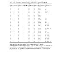
Intel and Compatible Processor Specifications 21<br />
Intel and Compatible Processor<br />
Specifications<br />
See Tables 2.3 and 2.4 to help determine the features of any CPU<br />
you encounter. It might be necessary to remove the heat sink or<br />
fan to see the processor markings on an older system, but many<br />
recent systems display CPU identification and speeds at startup.<br />
Table 2.4 shows the major Pentium-class CPUs made by companies<br />
other than Intel. The newest versions of these processors can often<br />
be used to upgrade an older Pentium—as long as proper voltage<br />
and system configuration information can be provided, either<br />
through adjusting the motherboard/BIOS settings or by purchasing<br />
an upgrade-type processor with third-party support.<br />
Footnotes for both tables follow Table 2.4.
22<br />
Chapter 2—System Components and Configuration<br />
Table 2.3 Intel Processor Specifications<br />
Internal<br />
Register Data Bus<br />
Processor CPU Clock Voltage Size Width<br />
8088 1x 5v 16-bit 8-bit<br />
8086 1x 5v 16-bit 16-bit<br />
286 1x 5v 16-bit 16-bit<br />
386SX 1x 5v 32-bit 16-bit<br />
386SL 1x 3.3v 32-bit 16-bit<br />
386DX 1x 5v 32-bit 32-bit<br />
486SX 1x 5v 32-bit 32-bit<br />
486SX2 2x 5v 32-bit 32-bit<br />
487SX 1x 5v 32-bit 32-bit<br />
486DX 1x 5v 32-bit 32-bit<br />
486SL 2 1x 3.3v 32-bit 32-bit<br />
486DX2 2x 5v 32-bit 32-bit<br />
486DX4 2–3x 3.3v 32-bit 32-bit<br />
486Pentium OD 2.5x 5v 32-bit 32-bit<br />
Pentium 60/66 1x 5v 32-bit 64-bit<br />
Pentium 75-200 1.5–3x 3.3-3.5v 32-bit 64-bit<br />
Pentium MMX 1.5–<br />
4.5x<br />
1.8–2.8v 32-bit 64-bit<br />
Pentium Pro 2–3x 3.3v 32-bit 64-bit<br />
Pentium II 3.5–<br />
4.5x<br />
1.8–2.8v 32-bit 64-bit<br />
Celeron 3.5–<br />
4.5x<br />
1.8–2.8v 32-bit 64-bit<br />
Celeron A 3.5–7x 1.8–2v 32-bit 64-bit<br />
Pentium II PE3 3.5–6x 1.6v 32-bit 64-bit<br />
Pentium II Xeon 4–4.5x 1.8–2.8v 32-bit 64-bit<br />
Pentium III Slot1 4.5–<br />
7.5x<br />
1.8–2v 32-bit 64-bit<br />
Pentium III PGA370 4–7x 1.8–2v 32-bit 64-bit<br />
Pentium III Xeon 5–6.5x varies 32-bit 64-bit
Intel and Compatible Processor Specifications 23<br />
L1 L2<br />
Max. Level 1 Cache L2 Cache Special<br />
Memory Cache Type Cache Speed Features<br />
1MB — — — — —<br />
1MB — — — — —<br />
16MB — — — — —<br />
16MB — — — Bus —<br />
16MB 0KB 1 WT — Bus —<br />
4GB — — — Bus —<br />
4GB 8KB WT — Bus —<br />
4GB 8KB WT — Bus —<br />
4GB 8KB WT — Bus FPU<br />
4GB 8KB WT — Bus FPU<br />
4GB 8KB WT — Bus FPU Opt.<br />
4GB 8KB WT — Bus FPU<br />
4GB 16KB WT — Bus FPU<br />
4GB 2x16KB WB — Bus FPU<br />
4GB 2x8KB WB — Bus FPU<br />
4GB 2x8KB WB — Bus FPU<br />
4GB 2x16KB WB — Bus FPU, MMX<br />
64GB 2x8KB WB 256KB,<br />
512KB,<br />
1MB<br />
Core FPU<br />
64GB 2x16KB WB 512KB 1/2<br />
Core<br />
FPU, MMX<br />
64GB 2x16KB WB 0KB — FPU, MMX<br />
64GB 2x16KB WB 128KB Core FPU, MMX<br />
64GB 2x16KB WB 256KB Core FPU, MMX<br />
64GB 2x16KB WB 512KB,<br />
1MB,<br />
2MB<br />
Core FPU, MMX<br />
64GB 2x16KB WB 512KB 1/2<br />
Core<br />
FPU, SSE<br />
64GB 2x16KB WB 256KB Core FPU, SSE<br />
64GB 2x16KB WB 512KB,<br />
1MB,<br />
2MB<br />
Core FPU, SSE
24<br />
Chapter 2—System Components and Configuration<br />
Table 2.4 Intel-Compatible Pentium-Class Processors<br />
Internal<br />
Register Data Bus Max.<br />
Processor CPU Clock Voltage Size Width Memory<br />
AMD K5 1.5–1.75x 3.5v 32-bit 64-bit 4GB<br />
AMD K6 2.5–4.5x 2.2–3.2v 32-bit 64-bit 4GB<br />
AMD K6-2 2.5–6x 1.9–2.4v 32-bit 64-bit 4GB<br />
AMD K6-3 3.5–4.5x 1.8–2.4v 32-bit 64-bit 4GB<br />
AMD Athlon 5–10x10 (nee K7)<br />
1.6–1.8v 32-bit 64-bit 8TB<br />
AMD Athlon, 5–10x10 with performance<br />
enhancing<br />
cache (PEC)<br />
(code name<br />
“Thunderbird”)<br />
1.8v 32-bit 64-bit 8TB<br />
AMD Duron9 6x–7.5x10 “Thunderbird”<br />
1.6–1.8v 32-bit 64-bit 8TB<br />
Cyrix 6x86 2x 2.5–3.5v 32-bit 64-bit 4GB<br />
Cyrix 6x86MX/MII 2–3.5x 2.2–2.9v 32-bit 64-bit 4GB<br />
VIA Cyrix III 2.5–7x 2.2v 32-bit 64-bit 4GB<br />
Nexgen Nx586 2x 4v 32-bit 64-bit 4GB<br />
IDT Winchip 3–4x 3.3–3.5v 32-bit 64-bit 4GB<br />
IDT Winchip2/2A 2.33–4x 3.3–3.5v 32-bit 64-bit 4GB<br />
Rise mP6 2–3.5x 2.8v 32-bit 64-bit 4GB<br />
FPU = Floating-Point unit (internal math coprocessor)<br />
WT = Write-through cache (caches reads only)<br />
WB = Write-back cache (caches both reads and writes)<br />
Bus = Processor external bus speed (motherboard speed)<br />
Core = Processor internal core speed (CPU speed)<br />
MMX = Multimedia extensions, 57 additional instructions for graphics and sound processing<br />
3DNow = MMX plus 21 additional instructions for graphics and sound processing<br />
SSE = Streaming SIMD (Single Instruction Multiple Data) Extensions, MMX plus 70 additional<br />
instructions for graphics and sound processing<br />
1. The 386SL contains an integral-cache controller, but the cache memory must be provided outside<br />
the chip.<br />
2. Intel later marketed SL Enhanced versions of the SX, DX, and DX2 processors. These processors<br />
were available in both 5v and 3.3v versions and included power-management capabilities.<br />
3. The Enhanced mobile PII has an on-die L2 cache similar to the Celeron.
Intel and Compatible Processor Specifications 25<br />
L1 L2<br />
Level 1 Cache Level 2 Cache Special<br />
Cache Type Cache Speed Features Similar to4 16+8KB WB — Bus FPU Pentium<br />
2x32KB WB — Bus FPU, MMX Pentium MMX<br />
2x32KB WB — Bus FPU, 3DNow Pentium MMX<br />
2x32KB WB 256KB Core FPU, 3DNow Pentium MMX<br />
2x64KB WB 512KB6 1/37 Core FPU, 3DNow Pentium III8 2x64KB WB 256KB Core FPU, 3DNow Pentium III<br />
2x64KB WB 64KB Core FPU, 3DNow Athlon PEC<br />
16KB WB — Bus FPU Pentium<br />
64KB WB — Bus FPU, MMX Pentium MMX<br />
64KB WB 256KB Core<br />
2x16KB WB — Bus FPU Pentium5 2x32KB WB — Bus FPU, MMX Pentium MMX<br />
2x32KB WB — Bus FPU, 3DNow AMD K6-2<br />
2x8KB WB — Bus FPU, MMX Pentium MMX<br />
4. These processors physically fit into the same Socket 7 used by Intel Pentium 75MHz and above<br />
models except as noted, but might require special chipsets or BIOS settings for best operation.<br />
Check with motherboard and chip mfr. before installing them in place of your existing<br />
Pentium-class chip.<br />
5. Pentium-class performance, but unique, non-standard pinout.<br />
6. Cache size for initial shipments (3rd Q 1999). Athlon designed it to allow cache sizes up to<br />
8MB.<br />
7. Athlon’s cache interface is designed to handle variable speed ratios, so later versions can run<br />
L2 cache more quickly.<br />
8. Athlon uses new AMD Slot A, physically similar to Slot 1 but with a different electrical pinout.<br />
9. Duron and “Thunderbird” versions of Athlon use new Socket A.<br />
10. Clock Multipliers listed based on 100MHz system bus (FSB) speeds; although Athlon and<br />
Duron use 200MHz bus, memory for these systems runs at PC100 or PC133 speeds, depending<br />
on the processor model.
26<br />
Chapter 2—System Components and Configuration<br />
Use Tables 2.5 and 2.6 to help determine which processors may fit<br />
in place of your existing CPU. Note that a replacement CPU must<br />
have the same pinout, the same electrical requirements, and be<br />
compatible with your motherboard. Many vendors sell upgradecompatible<br />
processor versions, which have been modified from<br />
their original forms by adding a voltage regulator and other support<br />
options.<br />
Table 2.5 Intel and Compatibles 486/Pentium-Class CPU Socket<br />
Types and Specifications<br />
Socket Supported<br />
Number Pins Pin Layout Voltage Processors<br />
Socket 1 169 17×17 PGA 5v 486 SX/SX2, DX/DX21 ,<br />
DX4 OverDrive<br />
Socket 2 238 19×19 PGA 5v 486 SX/SX2, DX/DX21 ,<br />
DX4 OverDrive, 486<br />
Pentium OverDrive<br />
Socket 3 237 19×19 PGA 5v/3.3v 486 SX/SX2, DX/DX2,<br />
DX4, 486 Pentium<br />
OverDrive, AMD 5x86,<br />
Cyrix 5x86<br />
Socket 4 273 21×21 PGA 5v Pentium 60/66,<br />
OverDrive<br />
Socket 5 320 37×37 SPGA 3.3/3.5v Pentium 75-133,<br />
OverDrive<br />
Socket 62 235 19×19 PGA 3.3v 486 DX4, 486 Pentium<br />
OverDrive<br />
Socket 7 321 37×37 SPGA VRM Pentium 75-233+, MMX,<br />
OverDrive, AMD K5/K6,<br />
Cyrix M1, VIA Cyrix MII<br />
Socket 8 387 dual pattern SPGA Auto VRM Pentium Pro<br />
PGA370 370 37×37 SPGA 2.0v Celeron, Pentium III, VIA<br />
Cyrix III<br />
Slot 1 242 Slot Auto VRM Pentium II/III, Celeron<br />
Slot 2 330 Slot Auto VRM Pentium II Xeon/<br />
Pentium III Xeon<br />
Slot A 242 Slot Auto VRM AMD Athlon (K7) SECC<br />
Socket A 462 SPGA Auto VRM AMD Duron/AMD<br />
Athlon PGA<br />
1. Non-overdrive DX4 or AMD 5x86 also can be supported with the addition of an aftermarket<br />
3.3v voltage-regulator adapter.<br />
2. Socket 6 was a paper standard only and was never actually implemented in any systems.<br />
PGA = Pin Grid Array.<br />
SPGA = Staggered Pin Grid Array.<br />
VRM = Voltage Regulator Module.
Table 2.6 lists the fastest processors you can install according to the<br />
socket type in your system. Note that newer socket designs allow<br />
faster processors, but that the bus speed and clock multiplier settings<br />
of your motherboard are also limiting factors for some CPU<br />
types.<br />
Table 2.6 Maximum Processor Speeds by Socket<br />
Socket Type Fastest Processor Supported<br />
Socket 1 5x86-133MHz with 3.3v adapter<br />
Socket 2 5x86-133MHz with 3.3v adapter<br />
Socket 3 5x86-133MHz<br />
Socket 4 Pentium OverDrive 133MHz<br />
Socket 5 Pentium MMX 233MHz or AMD K6 with 2.8v adapter<br />
Socket 7 AMD K6-2 up to 550MHz, K6-III up to 500MHz<br />
Socket 8 Pentium Pro OverDrive (333MHz Pentium II performance)<br />
Slot 1 Celeron 400MHz (66MHz bus)<br />
Slot 1 Pentium III 850MHz (100MHz bus)<br />
Slot 1 Pentium III 1.0GHz (133MHz bus)<br />
Slot 2 Pentium III Xeon 550MHz (100MHz bus)<br />
Slot 2 Pentium III Xeon 866MHz (133MHz bus)<br />
Socket 370 Celeron 600MHz (66MHz bus)<br />
Troubleshooting Processor Problems 27<br />
Socket 370 Pentium III 933MHz (100MHz bus)<br />
Slot A 1GHz AMD Athlon (K7) (200MHz bus), 1GHz AMD Athlon PEC<br />
(Thunderbird)<br />
Socket A 750MHz AMD Duron (200MHz bus), 1GHz AMD Athlon PEC<br />
(Thunderbird)<br />
Troubleshooting Processor<br />
Problems<br />
Table 2.7 provides a general troubleshooting checklist for processorrelated<br />
PC problems.
28<br />
Chapter 2—System Components and Configuration<br />
Table 2.7 Troubleshooting Processor-Related Problems<br />
Problem<br />
Identification Possible Cause Resolution<br />
System is dead, no Power cord failure. Plug in or replace power cord.<br />
cursor, no beeps, Power cords can fail even<br />
or no fan. though they look fine.<br />
Power supply Replace the power supply. Use<br />
failure. a known, good spare for testing.<br />
Motherboard Replace motherboard. Use a<br />
failure. known, good spare for testing.<br />
Memory failure. Remove all memory except one<br />
bank and retest. If the system still<br />
won’t boot, replace bank 1.<br />
System is dead, no All components Check all peripherals, especially<br />
beeps, or locks up either not installed memory and graphics adapter.<br />
before POST begins. or incorrectly installed.<br />
Reseat all boards and socketed<br />
components, such as CPUs and<br />
memory modules.<br />
System beeps on Improperly seated Reseat or replace graphics adapter.<br />
startup, fan is or failing graphics Use known, good spare for testing.<br />
running, no<br />
cursor onscreen.<br />
adapter.<br />
Locks up during Poor heat Check CPU heat sink/fan; replace if<br />
or shortly after dissipation. necessary, using one with a higher<br />
POST. capacity.<br />
Use thermal paste between<br />
fan/heatsink and CPU as directed<br />
by heatsink and CPU vendors.<br />
Improper voltage Set motherboard for proper core<br />
settings. processor voltage.<br />
Wrong motherboard<br />
bus speed.<br />
Set motherboard for proper speed.<br />
Wrong CPU clock Jumper motherboard for proper<br />
multiplier. clock multiplier.<br />
Improper CPU identification<br />
during POST.<br />
Old BIOS. Update BIOS from manufacturer.<br />
Board not Check manual and jumper board<br />
configured properly. according to proper bus and multiplier<br />
settings.<br />
If board is jumperless, adjust bus<br />
and multiplier in BIOS.
Table 2.7 Troubleshooting Processor-Related Problems Continued<br />
Problem<br />
Identification Possible Cause Resolution<br />
Operating system Poor heat Check CPU fan; replace if<br />
will not boot. dissipation. necessary. May need higher capacity<br />
heat sink and thermal paste.<br />
Improper voltage Jumper motherboard for proper<br />
settings. core voltage.<br />
Wrong motherboard Jumper motherboard or adjust<br />
bus speed. BIOS settings to correct speed.<br />
Wrong CPU clock Jumper motherboard or adjust<br />
multiplier. BIOS settings to correct multiplier.<br />
Applications will Improper drivers or incompatible<br />
not install or run. hardware. Update drivers and<br />
check for compatibility issues.<br />
System appears Monitor turned Check monitor and power to<br />
to work but no off or failed. monitor. Replace with knownvideo<br />
is displayed good spare for testing.<br />
If, during POST, the processor is not identified correctly, your<br />
motherboard settings might be incorrect or your BIOS might need<br />
to be updated. Check that the motherboard is jumpered or configured<br />
correctly for the processor that you have, and make sure that<br />
you have the latest BIOS for your motherboard.<br />
If the system seems to run erratically after it warms up, try setting<br />
the processor to a lower speed. If the problem goes away, the<br />
processor might be defective or overclocked.<br />
Many hardware problems are really software problems in disguise.<br />
Be sure you have the latest BIOS for your motherboard and the latest<br />
drivers for your peripherals. Also, it helps to use the latest version<br />
of your given operating system because, normally, fewer<br />
problems will occur.<br />
Note<br />
Motherboard Form Factors 29<br />
For more information about processors, see Chapter 3 of<br />
Upgrading and Repairing <strong>PCs</strong>, 12th Edition, also published by Que.<br />
Motherboard Form Factors<br />
Although many PC users have extended the life span of their systems<br />
by changing the CPU, any system that will be kept for a long<br />
time could be a candidate for a motherboard replacement. Use the<br />
following charts to determine whether your system uses one of
30<br />
Chapter 2—System Components and Configuration<br />
these standard form factors, which will allow you the choice of<br />
many vendors for a replacement. A replacement motherboard provides<br />
you with these benefits:<br />
• Access to faster, more advanced CPUs<br />
• “Free” updated BIOS with support for large hard drives; Y2K;<br />
and boot from LS-120, Zip, and CD-ROM drives<br />
• Newer I/O features, such as USB ports, UDMA-66 hard disk<br />
interfacing, and AGP video<br />
Baby-AT Motherboard<br />
Until mid-1996, this descendent of the original IBM/XT motherboard<br />
was the dominant design. Even though limited numbers of<br />
these motherboards are still available for use with both Pentiumclass<br />
and Pentium II/III/Celeron processors, the lack of built-in ports<br />
and cooling problems make this an obsolete design. If you are trying<br />
to upgrade a system that uses this motherboard design, consider<br />
purchasing a new ATX-style case, power supply, and motherboard.<br />
In addition, you should consider moving the CPU, RAM, drives, and<br />
cards from your existing system to the new box (see Figure 2.1).<br />
13.04"<br />
6.50"<br />
.34"<br />
.65"<br />
.45"<br />
3.75"<br />
.40"<br />
5.55"<br />
8.35"<br />
8.57"<br />
Figure 2.1 Baby-AT motherboard form factor dimensions.<br />
6.00"
LPX Motherboard<br />
Motherboard Form Factors 31<br />
Since 1987, many low-cost systems have used variations on this layout,<br />
which features a single slot used for a riser card. The expansion<br />
cards for video, audio, and so forth are connected to the riser card,<br />
not the motherboard. Most LPX systems use riser cards that mount<br />
the expansion slots parallel to the motherboard; some use a T-shaped<br />
riser card that keeps the expansion slots at their normal upright position.<br />
Additionally, most LPX systems have built-in video, audio, and<br />
other I/O ports. Unfortunately, because its details were never standardized,<br />
it is virtually impossible to upgrade. Systems with this<br />
motherboard are essentially disposable (see Figure 2.2).<br />
<br />
<br />
<br />
<br />
<br />
<br />
<br />
<br />
<br />
<br />
<br />
<br />
<br />
<br />
<br />
Figure 2.2 Typical LPX system chassis and motherboard.<br />
<br />
<br />
<br />
<br />
ATX Motherboard<br />
Since mid-1996, the ATX motherboard has become the standard<br />
for most systems using non-proprietary motherboards (see Figure<br />
2.3). Similar to Baby-AT, it’s also an industry standard, and similar<br />
to LPX, it features built-in ports. Compared to both, though, it<br />
offers much greater ease of upgrading and servicing. ATX motherboards<br />
are rotated 90 degrees when compared to Baby-ATs and also<br />
use a different power supply for advanced power management features.<br />
Because of their built-in ports and differences in layout, ATX<br />
motherboards require an ATX case. ATX cases can also be used for<br />
Baby-AT motherboards, though. Figure 2.3 shows a full-size ATX<br />
layout; however, several smaller versions now exist, including<br />
mini-ATX, micro-ATX, and flex-ATX.
32<br />
Chapter 2—System Components and Configuration<br />
Double high<br />
expandable I/O<br />
Full<br />
length slots<br />
Floppy/IDE<br />
connectors close<br />
to peripheral bays<br />
Figure 2.3 ATX system chassis layout and features.<br />
NLX Motherboard<br />
3 1/2"<br />
Bay<br />
Processor<br />
Single<br />
chassis fan<br />
CPU located<br />
near PSU<br />
Single power<br />
connector<br />
Easy to access<br />
SIMM memory<br />
The replacement for the old LPX low-profile motherboard is the<br />
NLX motherboard (see Figure 2.4). NLX also features built-in ports<br />
and a riser card, but its standard design means that replacement<br />
motherboards should be easier to purchase than those for LPX systems.<br />
A major advantage of NLX systems is that the motherboard is<br />
easy to remove for servicing through a side panel, a feature that<br />
makes NLX-based systems popular as corporate network client <strong>PCs</strong>.<br />
5 1/4"<br />
Bay<br />
Power<br />
Supply<br />
Figure 2.4 NLX motherboard and riser combination.<br />
Which Motherboard Is Which?<br />
Use Table 2.8 to help determine whether a system is a Baby-AT, an<br />
LPX, an ATX, or an NLX-based system.
Table 2.8 Comparison of Major Motherboard Form Factors<br />
Baby-AT LPX<br />
ATX/<br />
Micro ATX1 NLX WTX<br />
Ports built No Yes Yes Yes No2 into chassis<br />
Riser card No Yes No Yes No<br />
Single row of<br />
ports at rear<br />
N/A Yes No No No<br />
Two rows of N/A No Yes Yes No3 ports at rear<br />
Slots on both<br />
sides of riser<br />
card<br />
N/A Opt N/A No N/A<br />
Riser card N/A Middle N/A Side near N/A<br />
location power<br />
on MB supply<br />
1. MicroATX motherboards can fit into ATX cases, but have fewer slots and are designed for<br />
socketed, rather than slot-based, processors. They also usually feature onboard audio and<br />
video, both of which are usually optional on ATX motherboards.<br />
2. WTX supports a FlexSlot design, which uses a single modified PCI slot for all standard ports.<br />
3. The layout of ports on the rear of a FlexSlot resembles the layout on the rear of an ATX or a<br />
MicroATX motherboard, but they are vertically oriented because they are attached to a<br />
FlexSlot. See www.wtx.org for more information.<br />
PC99 Color-Coding for Ports<br />
Microsoft and Intel have developed the following standardized<br />
color-coding of connectors for computers compliant with the PC99<br />
design standards. Use Table 2.9 to help you match non–color-coded<br />
peripherals with the correct external ports.<br />
Note<br />
Some systems, especially those built before 1999, might use a<br />
proprietary color scheme for ports.<br />
Check the inside front and back covers of this book for pictures of<br />
these ports. For color samples, see the following Web site:<br />
http://www.pcdesguide.com/documents/pc99icons.htm<br />
Table 2.9 PC99 Color-Coding Standards for Ports<br />
Port Type Color<br />
Analog VGA (DB15) Blue<br />
Audio line in Light blue<br />
Audio line out Lime green<br />
Digital monitor White<br />
PC99 Color-Coding for Ports 33
34<br />
Chapter 2—System Components and Configuration<br />
Table 2.9 PC99 Color-Coding Standards for Ports Continued<br />
Port Type Color<br />
IEEE-1394 (i.Link, FireWire) Grey<br />
Microphone Pink<br />
MIDI/Gameport Gold<br />
Parallel port Burgundy<br />
Serial port Teal or turquoise<br />
Speaker out (subwoofer) Orange<br />
Right-to-left speaker Brown<br />
USB Black<br />
Video out Yellow<br />
SCSI, network, telephone,<br />
modem, and so on<br />
None<br />
Power Supplies<br />
Power supplies actually convert high-voltage AC (alternating current)<br />
into low-voltage DC (direct current) for use by <strong>PCs</strong>. Power<br />
supplies come in several form factors, and they also feature various<br />
motherboard connectors to correspond with the newer motherboard<br />
designs on the market. Table 2.10 illustrates which power<br />
supplies are most likely to be used with various motherboards.<br />
Table 2.10 Matching Power Supplies and Motherboards<br />
Motherboard Most Common PS Other PS Form<br />
Form Factor Form Factor Used Factors Used<br />
Baby-AT LPX style Baby-AT, AT/Tower,<br />
or AT/Desk<br />
LPX LPX style None<br />
ATX ATX style None<br />
MicroATX ATX style SFX style<br />
NLX ATX style None<br />
LPX Versus ATX Power Supplies<br />
Some motherboards are designed to handle either LPX or ATX<br />
power supplies. The ATX is the preferred design because it provides<br />
the lower voltage needed by today’s CPUs, offers foolproof installation,<br />
and also provides better cooling than older designs.<br />
Table 2.11 compares two of the more common power supply form<br />
factors used in computers today, and Figure 2.5 shows an LPX<br />
power supply.
Table 2.11 Comparing ATX and LPX Power Supplies<br />
Power Supplies 35<br />
Power Motherboard<br />
Supply Voltage Power Other<br />
Type Output Connectors Features Notes<br />
LPX 5v, 12v 2–6 pins Easy to reverse the<br />
each (P8/P9) plug due to poor keying<br />
ATX 3.3v, 5v, 12v 1–20 pins Keyed to go in only one<br />
way; allows hibernation via<br />
operating system or keyboard<br />
command<br />
86mm<br />
6mm<br />
64mm<br />
86mm<br />
16mm<br />
5 138mm<br />
7<br />
+<br />
+<br />
5 115mm<br />
150mm<br />
Figure 2.5 LPX form factor power supply.<br />
140mm<br />
+<br />
+<br />
30mm<br />
+5V<br />
G<br />
G<br />
+12V<br />
+5V<br />
G<br />
G<br />
+12V<br />
+5V<br />
G<br />
G<br />
+12V<br />
Table 2.12 breaks down the typical LPX power supply connector.<br />
6<br />
+5V<br />
G<br />
G<br />
+12V<br />
P.G.<br />
+5V<br />
+12V<br />
-12V<br />
G<br />
G<br />
G<br />
G<br />
-5V<br />
+5V<br />
+5V<br />
+5V
36<br />
Caution<br />
Chapter 2—System Components and Configuration<br />
To get the cables oriented correctly, keep the ground wires<br />
(black) next to each other. Although most connectors are keyed<br />
to prevent improperly plugging them in, some connectors can<br />
easily be inserted incorrectly. This will cause your motherboard<br />
to be destroyed the first time you switch on the power and<br />
could possibly cause a fire.<br />
Table 2.12 Typical LPX Power Supply Connections<br />
Connector Voltage Standard Color/Notes<br />
P8-1 Power_Good (+5v) Orange<br />
P8-2 +5v Red<br />
P8-3 +12v Yellow<br />
P8-4 -12v Blue<br />
P8-5 Ground (0) Black<br />
P8-6 Ground (0) Black<br />
P9-1 Ground (0) Black<br />
P9-2 Ground (0) Black<br />
P9-3 -5v White<br />
P9-4 +5v Red<br />
P9-5 +5v Red<br />
P9-6 +5v Red<br />
Power Connectors for the Drive(s)<br />
The connectors shown in Table 2.13 might not be labeled, but they<br />
easily can be distinguished by the four-wire cable and color-coding.<br />
The same colors are used for drive power connectors on ATX power<br />
supplies. Figure 2.6 shows an ATX power supply.<br />
Table 2.13 ATX Power Supply Color Coding<br />
Connector Voltage Standard Color/Notes<br />
P10-1 +12v Yellow<br />
P10-2 Ground (0) Black<br />
P10-3 Ground (0) Black<br />
P10-4 +5v Red
86mm<br />
6mm<br />
64mm<br />
86mm<br />
16mm<br />
5 138mm<br />
7<br />
+<br />
+<br />
140mm<br />
5 115mm<br />
150mm<br />
+<br />
+<br />
30mm<br />
6<br />
+5V<br />
G<br />
G<br />
+12V<br />
+5V<br />
G<br />
G<br />
+12V<br />
+5V<br />
G<br />
G<br />
+12V<br />
+5V<br />
G<br />
G<br />
+12V<br />
Power Supplies 37<br />
3.3V*<br />
11 1<br />
3.3V*<br />
12 2<br />
-12V<br />
3.3V*<br />
13 3<br />
COM<br />
COM<br />
14 4<br />
PS-ON<br />
5V<br />
15 5<br />
COM<br />
COM<br />
16 6<br />
COM<br />
5V<br />
17 7<br />
COM<br />
COM<br />
18 8<br />
-5V<br />
PW-OK<br />
5V<br />
19 9<br />
5VSB<br />
20 10<br />
5V<br />
12V<br />
*optional<br />
ATX Power connector pin out<br />
Figure 2.6 ATX form factor power supply used with both ATX and NLX<br />
systems. The pinout for the motherboard power is shown at lower right.<br />
Note the single square pin used for keying.<br />
Table 2.14 shows the pinout for the ATX motherboard power connector.<br />
Table 2.14 ATX Motherboard Power Supply Connections<br />
Color Signal Pin Pin Signal Color<br />
Orange +3.3v 11 1 +3.3v Orange<br />
Blue -12v 12 2 +3.3v Orange<br />
Black GND 13 3 GND Black<br />
Green PS_On 14 4 +5v Red<br />
Black GND 15 5 GND Black<br />
Black GND 16 6 +5v Red<br />
Black GND 17 7 GND Black<br />
White -5v 18 8 Power_Good Grey<br />
Red +5v 19 9 +5VSB<br />
(Standby)<br />
Purple<br />
Red +5v 20 10 +12v Yellow<br />
Quick-Reference Chart for Troubleshooting Power<br />
Supplies<br />
Table 2.15 Troubleshooting Power Supplies<br />
Symptom Cause(s) Tests and Solution(s)<br />
Overheating. Inadequate system cooling Check ventilation around system;<br />
clean system internally; check for<br />
missing slot covers.<br />
Higher load on system in Replace power supply with higher<br />
watts than power supply rated unit.<br />
rating
38<br />
Table 2.15 Troubleshooting Power Supplies Continued<br />
Symptom Cause(s) Tests and Solution(s)<br />
System reboots Incorrect power level on Use DC-voltage digital multimeter<br />
itself. Power_Good; can indicate (DMM) to test P8-1 (orange wire)<br />
overloaded power supply on LPX and older power supplies<br />
or otherwise bad unit or Pin 8 (gray wire) on ATX and<br />
newer power supplies; rated voltage<br />
is +5v; acceptable is +3.0v to<br />
+6.0v.<br />
Replace failed power supply with<br />
higher rated unit.<br />
Fan turns for Wrong voltage (PS set to Turn off system; reset PS to<br />
only a moment 220/230v in U.S.) correct voltage (110/115v in<br />
and then stops. U.S.) and restart. Using 220/230v<br />
power on a PS set for 110/115v<br />
will destroy it!<br />
Dead short in system Short can be caused by loose<br />
screws, failed hard drives, or addon<br />
cards.<br />
Turn off and unplug system; disconnect<br />
hard drive and see<br />
whether system starts. If system<br />
still fails, plug in drive and remove<br />
add-on card; repeat until each<br />
card and drive has been checked;<br />
also check Y-adapter cables<br />
because bad cables can cause<br />
shorts.<br />
Note<br />
Chapter 2—System Components and Configuration<br />
Replace faulty component(s).<br />
For more information on power supplies, wattage ratings, and<br />
testing, see Chapter 21 of Upgrading and Repairing <strong>PCs</strong>, 12th<br />
Edition, published by Que.<br />
Memory Types<br />
RAM (random access memory) provides the work area that processors<br />
use to create and modify data. While RAM was sometimes<br />
found on expansion boards on old XT-class and early AT-class systems,<br />
all standard 486-based and Pentium-class systems have their<br />
memory modules attached to the motherboard.<br />
Memory modules come in two major forms: SIMMs and DIMMs.<br />
SIMM stands for single-sided inline memory module, and DIMM<br />
stands for dual-sided inline memory module. These terms refer to<br />
the pin configurations used on the module, rather than the location<br />
of the memory chips on the module.
The following features are common to all SIMMs:<br />
• Pins numbered from left to right<br />
• Same pins on both sides of the module<br />
Memory Types 39<br />
Tip<br />
Note that all dimensions for both SIMMs and DIMMs in the following<br />
figures are in both inches and millimeters (in parentheses).<br />
30-Pin SIMM<br />
The 30-pin SIMM is the oldest type of memory module still in use<br />
(see Figure 2.7). It was popular on 386-based and early 486-based<br />
systems, but became obsolete with the rise of Pentium-class 64-bit<br />
CPUs. Although its capacities are extremely small compared to<br />
more modern memory designs, its unpopularity since the early<br />
1990s makes the 30-pin SIMM the most expensive memory type<br />
per megabyte. If you are still supporting systems that use this type<br />
of module, look for sources of used memory or replace the motherboard<br />
with one that uses newer, 72-pin SIMM or DIMM memory<br />
instead of buying new 30-pin modules.<br />
.250 (6.35)<br />
TYP.<br />
.080 (2.03)<br />
TYP.<br />
PIN 1<br />
3.505 (89.03)<br />
3.495 (88.77)<br />
.100 (2.54)<br />
TYP.<br />
.400 (10.16)<br />
TYP.<br />
.070 (1.78)<br />
TYP.<br />
.653 (16.59)<br />
.647 (16.43)<br />
.133 (3.38)<br />
TYP.<br />
.055 (1.40)<br />
.047 (1.19)<br />
.200 (5.08)<br />
MAX.<br />
Figure 2.7 A typical 30-pin SIMM. The one shown here is 9-bit,<br />
although the dimensions would be the same for 8-bit.<br />
72-Pin SIMM<br />
The 72-pin SIMM was the most popular for a number of years, but<br />
has now been superseded on newer systems by DIMM modules. 72pin<br />
SIMMs are commonly found on late-model 486-based systems,<br />
most Pentiums, and most early Pentium-compatible systems.<br />
Because these modules are also becoming very expensive per<br />
megabyte, try to salvage or swap memory to populate older systems<br />
rather than purchase new. 72-pin SIMMs can be either fast-page or<br />
extended data out (EDO). 486-class systems can use only fast-page<br />
SIMMs, but Pentium-class systems that use SIMMs can use either<br />
type. Fast-page and EDO SIMMs should not be mixed. Some
40<br />
Chapter 2—System Components and Configuration<br />
systems require BIOS configuration to optimize performance if you<br />
install EDO memory (see Figure 2.8).<br />
.125 (3.18)<br />
TYP<br />
.250<br />
(6.35)<br />
.080 (2.03)<br />
PIN 1<br />
1.75 (44.45) TYP<br />
4.260 (108.20)<br />
4.240 (107.70)<br />
.250 (6.35)<br />
3.75 (95.25)<br />
Figure 2.8 A typical 72-pin SIMM, although the dimensions would be<br />
the same for 32-bit.<br />
DIMMs<br />
DIMMs became popular with the rise of the Pentium II/III/Celeron<br />
family of processors—AMD’s Athlon series—and can also be found<br />
on many late-model Pentium and “Super Socket 7” motherboards<br />
used with AMD K6-series and Cyrix 6x86MX/MII processors (see<br />
Figure 2.9). DIMMs are the most popular and fastest type of memory<br />
module in widespread use. Most DIMMs are Synchronous<br />
DRAM (SDRAM). On motherboards with both SIMM and DIMM<br />
sockets, SDRAMs cannot be used in conjunction with SIMMs, but<br />
the relatively rare EDO DIMMs can be used along with EDO<br />
SIMMs.<br />
.050 (1.27)<br />
TYP<br />
The following features are common to all DIMMs:<br />
• Three edge connectors of varying widths for positive keying<br />
.040 (1.02)<br />
TYP<br />
• Different pinouts on each side of the DIMM<br />
.079 (2.00) R<br />
(2X)<br />
.118 (3.00) R<br />
(2X)<br />
.118 (3.00) TYP<br />
.118 (3.00)<br />
TYP<br />
FRONT VIEW<br />
5.260 (133.80)<br />
5.240 (133.00)<br />
.250 (6.35) TYP<br />
1.661 (42.18)<br />
.039 (1.00)R (2X)<br />
.39 (1.27)<br />
2.625 (66.68)<br />
TYP<br />
PIN 1 (PIN 85 ON BACKSIDE)<br />
4.550 (115.57)<br />
.050 (1.27)<br />
TYP<br />
+<br />
.133 (3.38)<br />
TYP<br />
.235 (5.97)<br />
MIN<br />
1.010 (25.65)<br />
.990 (25.15)<br />
.400 (10.16)<br />
TYP<br />
– 1.260 (32.00)<br />
1240 (31.50)<br />
.700 (17.7B)<br />
TYP<br />
.128 (3.25)<br />
.118 (3.00) (2x)<br />
PIN 84 (PIN 168 ON BACKSIDE)<br />
.350 (8.98)<br />
MAX<br />
.054 (1.37)<br />
.047 (1.19)<br />
.350 (8.89)<br />
MAX<br />
.054 (1.37)<br />
.046 (1.17)<br />
Figure 2.9 A typical 168-pin DIMM. The one shown here is 72-bit,<br />
although the dimensions would be the same for 64-bit.<br />
RDRAM<br />
The RDRAM, or Rambus DRAM, is a radical new memory design that<br />
is slowly appearing in high-end PC systems that use Intel chipsets.<br />
RDRAM differs from previous memory devices in that it provides<br />
multiple high-speed (800MHz), narrow-channel (16-bit–wide) data
Memory Types 41<br />
transfers to and from a 128-bit memory bus instead of the slower<br />
(100MHz or 66MHz), 32-bit or 64-bit data transfers of SDRAM and<br />
previous memory types.<br />
RDRAM modules are called RIMMs (Rambus Inline Memory Module),<br />
and any unused RIMM slots on a motherboard must be filled with<br />
a continuity module to permit a continuous high-speed data pathway<br />
through the RIMMs (see Figure 2.10). Each RIMM represents<br />
multiple memory banks, and thus a single RIMM at a time can be<br />
added to a system—much the way installation of DIMMs works,<br />
although the memory types are not interchangeable.<br />
1.00 [0.039] 3.00 [0.118]<br />
Detail A<br />
4.00 [0.157]<br />
5.675 [0.2234]<br />
REF.<br />
A-1<br />
+<br />
COMPONENT AREA<br />
(A SIDE)<br />
+<br />
B-1<br />
133.35 +0.15<br />
-0.15 5.250+0.006<br />
-0.006<br />
+<br />
Detail B<br />
1.00[0.039]<br />
11.50[0.453]<br />
4.50[1.772]<br />
45.00[1.777]<br />
27.50[1.083]<br />
45.00[1.772]<br />
+0.08<br />
55.18<br />
-0.08<br />
78.17[3.078]<br />
REF.<br />
2.172+0.003<br />
-0.003<br />
-A-<br />
+<br />
+<br />
COMPONENT AREA<br />
(B SIDE)<br />
+<br />
+<br />
+<br />
B-92<br />
17.78 [0.700]<br />
0.85 [0.033]<br />
4.00 +0.15<br />
-0.15 0.157+0.006<br />
-0.006<br />
-B-<br />
A-92<br />
1.27 +0.10<br />
-0.10<br />
0.050 +0.004<br />
-0.004<br />
+0.10<br />
3.00<br />
-0.10<br />
0.80 +0.10<br />
Detail B<br />
-0.10<br />
TYP. 184 PLCS<br />
0.15 +0.10<br />
-0.10<br />
3XScale<br />
2.99 +0.05<br />
-0.05<br />
Capacitor<br />
CSP<br />
Note: Components<br />
Not Always Present<br />
on B side<br />
0.75-1.35<br />
[0.030-0.053]<br />
-C-<br />
+<br />
3XScale<br />
Figure 2.10 Typical RDRAM bus layout, showing two RIMMs and one<br />
continuity module installed.<br />
DDR SDRAM<br />
Double Data Rate (DDR) SDRAM memory is an improved version of<br />
standard SDRAM in which data is transferred twice as fast. Instead<br />
of doubling the actual clock rate, DDR memory achieves the doubling<br />
in performance by transferring twice per transfer cycle—once<br />
at the leading (falling) and once at the trailing (rising) edge of the<br />
cycle. This is similar to the way RDRAM operates and effectively<br />
doubles the transfer rate, even though the same overall clock and<br />
timing signals are used.<br />
DDR SDRAM is supported by many of the newest server chipsets<br />
and provides a design alternative to the more radical RDRAM. The<br />
DDR Consortium—an industry panel consisting of Fujitsu, Ltd.;<br />
Hitachi, Ltd.; Hyundai Electronics Industries Co.; Mitsubishi<br />
Electric Corp.; NEC Corp.; Samsung Electronics Co.; Texas<br />
Instruments, Inc.; and Toshiba Corp.—undertook official standardization<br />
of DDR.<br />
2.00 +0.10<br />
-0.10<br />
3.99 +0.10<br />
-0.10<br />
DDR-SDRAM uses a new DIMM module design with 184 pins.<br />
Figure 2.11 shows the DDR SDRAM DIMM.
42<br />
Chapter 2—System Components and Configuration<br />
Startup and<br />
observe POST.<br />
If errors are<br />
encountered,<br />
go to defect<br />
isolation<br />
procedures.<br />
Defect<br />
Isolation<br />
Procedures.<br />
If count does<br />
not match, go to<br />
defect isolation<br />
procedures.<br />
If problems are<br />
encountered, go<br />
to Defect Isolation<br />
Procedures.<br />
If POST completes<br />
with no errors,<br />
basic functionality<br />
has been tested.<br />
Restart system,<br />
enter Bios (or CMOS)<br />
setup. Verify that<br />
memory count is<br />
equal to installed<br />
amount.<br />
While in the BIOS,<br />
set all cache options<br />
to disabled, save<br />
settings and boot to<br />
a DOS formatted<br />
(floppy) system disk.<br />
Use a diagnostics<br />
program to test<br />
system base and<br />
extended memory.<br />
If no problems are<br />
encountered, memory<br />
has tested OK.<br />
Reboot, enter BIOS<br />
setup re-enable.<br />
Figure 2.11 184-pin DDR (Double Data Rate) SDRAM DIMM.<br />
DDR DIMMs are rated for either PC200 (100MHz x 2) or PC266<br />
(133MHz x 2) operation and normally run on 2.5 volts. They are<br />
basically an extension of the PC100 and PC133 DIMMs redesigned<br />
to support double clocking, where data is sent on each clock transition<br />
(twice per cycle) rather than once per cycle as is standard with<br />
SDRAM.<br />
Parity Versus Non-Parity Memory<br />
Parity-checked RAM uses units of 8 memory bits plus 1 parity bit,<br />
for a total of 9 bits. In addition, parity checking uses both the data<br />
bits and the parity bit to ensure that memory contents are accurate<br />
with each memory access.<br />
Virtually all 386-based and older systems, and most 486-based systems,<br />
require parity-checked memory, which can detect, but not<br />
correct, memory errors. On the other hand, most Pentium-class
and higher systems don’t require parity-checked RAM, but will<br />
ignore the parity bit(s) if present.<br />
Parity-checked memory must be used on systems that require it,<br />
and should be used on systems that can be configured to use the<br />
parity bits, especially if the systems support ECC (Error Correction<br />
Code) operation, which uses the parity bit as a means of correcting a<br />
faulty memory bit.<br />
Requirements for ECC Memory Use<br />
ECC requires the following:<br />
• Parity-checked memory modules<br />
• A motherboard chipset that offers ECC support<br />
• ECC support enabled in the BIOS system configuration<br />
ECC operation is recommended for servers and other systems that<br />
are performing mission-critical tasks because ECC operation can<br />
correct single-bit memory errors. Larger memory errors will cause<br />
the system to display an error message and halt.<br />
However, systems using ECC will cost more due to the higher cost<br />
of parity-checked RAM. Additionally, system performance is slightly<br />
slower due to the extra time involved in ECC operation. Check<br />
your motherboard or system documentation to determine whether<br />
ECC is an option for your system.<br />
To determine whether a memory module supports parity-checking<br />
or ECC, use the following tips.<br />
Using the Divide by 3 Rule to Determine Parity Support<br />
Count the chips on a SIMM or DIMM. If you can divide the number<br />
of chips by 3, the module is most likely a parity-checked module.<br />
However, some memory manufacturers have created memory<br />
modules with fake parity chips; these are referred to as logic parity<br />
modules.<br />
Note<br />
Memory Types 43<br />
See Upgrading and Repairing <strong>PCs</strong>, 12th Edition, Chapter 6, for<br />
more information about how to detect a logic parity module.<br />
Using the Divide by 9 Rule to Determine Parity Support<br />
A similar “divide by 9” rule can also be used to determine parity<br />
checking if you know the number of memory bits in the module.<br />
Note in Table 2.16 that the number of bits in parity-checked
44<br />
modules can be divided by 9, but the number of bits in non-parity<br />
modules can be divided only by 8.<br />
Table 2.16 SIMM and DIMM Capacities<br />
30-Pin SIMM Capacities<br />
Capacity Parity SIMM Non-Parity SIMM<br />
256KB 256KB×9 256KB×8<br />
1MB 1MB×9 1MB×8<br />
4MB 4MB×9 4MB×8<br />
16MB 16MB×9 16MB×8<br />
72-Pin SIMM Capacities<br />
Capacity Parity SIMM Non-Parity SIMM<br />
1MB 256KB×36 256KB×32<br />
2MB 512KB×36 512KB×32<br />
4MB 1MB×36 1MB×32<br />
8MB 2MB×36 2MB×32<br />
16MB 4MB×36 4MB×32<br />
32MB 8MB×36 8MB×32<br />
64MB 16MB×36 16MB×32<br />
128MB 32MB×36 32MB×32<br />
168-Pin DIMM Capacities<br />
Chapter 2—System Components and Configuration<br />
Capacity Parity DIMM Non-Parity DIMM<br />
8MB 1MB×72 1MB×64<br />
16MB 2MB×72 2MB×64<br />
32MB 4MB×72 4MB×64<br />
64MB 8MB×72 8MB×64<br />
128MB 16MB×72 16MB×64<br />
256MB 32MB×72 32MB×64<br />
Expanding Memory on a System<br />
Memory must be added to a system in banks. Simply put, a bank of<br />
memory is the amount of RAM in bits equal to the data bus width<br />
of the computer’s CPU (see Table 2.17). Thus, a Pentium’s data bus<br />
is 64 bits, and a memory module(s) used with a Pentium must have<br />
a total width of 64 bits for non-parity memory and 72 bits for<br />
parity-checked or ECC memory.
Table 2.17 Memory Bank Widths on Various Systems<br />
Memory Types 45<br />
30-Pin 72-Pin 168-Pin<br />
Memory Memory SIMMs SIMMs SIMMs<br />
Data Bank Size Bank Size per per per<br />
Processor Bus (No Parity) (Parity) Bank Bank Bank<br />
8088 8-bit 8 bits 9 bits 1 n/a n/a<br />
8086 16-bit 16 bits 18 bits 2 n/a n/a<br />
286 16-bit 16 bits 18 bits 2 n/a n/a<br />
386SX,<br />
SL, SLC<br />
16-bit 16 bits 18 bits 2 n/a n/a<br />
386DX 32-bit 32 bits 36 bits 4 1 n/a<br />
486SLC,<br />
SLC2<br />
16-bit 16 bits 18 bits 2 n/a n/a<br />
486SX,<br />
DX, DX2,<br />
DX4, 5x86<br />
32-bit 32 bits 36 bits 4 1 n/a<br />
Pentium, 64-bit 64 bits 72 bits 8 1<br />
K5, K6<br />
6x86,<br />
6x86MX,<br />
MII<br />
2 1<br />
Pentium 64-bit 64 bits 72 bits 8 1<br />
Pro, PII,<br />
PIII, Celeron,<br />
Xeon, AMD<br />
Athlon,<br />
Duron, Intel<br />
Itanium<br />
2 1<br />
1. Very few motherboards for these processors actually use this type of memory.<br />
The number of bits for each bank can be made up of single chips, SIMMs, or DIMMs. Modern<br />
systems don’t use individual chips; instead, they use only SIMMs or DIMMs. If the system has a<br />
16-bit processor, such as a 386SX, it probably uses 30-pin SIMMs and has two SIMMs per bank.<br />
All the SIMMs in a single bank must be the same size and type.<br />
Memory Troubleshooting<br />
Figure 2.12 provides basic steps that enable you to effectively test<br />
and troubleshoot your system RAM. First, let’s cover the memory<br />
testing and troubleshooting procedures.<br />
After you’ve determined that the system’s memory is defective, you<br />
need to determine which memory module is at fault. Follow the<br />
procedure in Figure 2.13 to isolate the module for replacement.
46<br />
Chapter 2—System Components and Configuration<br />
Restart system and<br />
enter BIOS setup under<br />
advanced or chipset<br />
setup, select memory<br />
timing parameters and<br />
set all to BIOS defaults.<br />
Save settings and reboot.<br />
Retest as shown in<br />
Figure 6.17.<br />
Problem<br />
not solved<br />
Open your system case.<br />
Identify the SIMMS/<br />
DIMMS/RIMMS.<br />
Determine the bank<br />
arrangement. Remove<br />
and reinstall all of the<br />
memory modules to<br />
reseat them. Ensure that<br />
they are the correct size,<br />
speed, voltage, and type<br />
for your system.<br />
If problem remains with<br />
all but 1st bank removed,<br />
problem isolated to 1st<br />
bank. Replace memory<br />
modules.<br />
Problem solved<br />
Problem solved<br />
If problem does not<br />
recur after removing/<br />
replacing modules, could<br />
be that contacts need<br />
cleaned.<br />
Problem<br />
not solved<br />
Problem solved<br />
Figure 2.12 Testing and troubleshooting memory.<br />
Memory Usage Within the System<br />
Note which are the<br />
slowest.<br />
If problem was solved,<br />
the improper BIOS<br />
settings were the culprit.<br />
If problem is solved with<br />
all but bank 1 removed,<br />
the problem could be in<br />
one of the modules you<br />
removed. Add 1 at a time,<br />
and retest. When problem<br />
appears, replace module.<br />
If problem still remains<br />
after all banks are tested,<br />
replace motherboard.<br />
The original PC had a total of 1MB of addressable memory, and the<br />
top 384KB of that was reserved for use by the system. Placing this<br />
reserved space at the top (between 640KB and 1,024KB instead of at<br />
the bottom, between 0KB and 640KB) led to what is often called the<br />
conventional memory barrier. Systems with more than 1MB of RAM<br />
treat the additional RAM as extended memory, beginning at 1MB.<br />
Thus, there is a “hole” in memory usage between 640KB and 1MB.<br />
Some standard add-on cards and motherboard devices use part of<br />
this memory area for RAM and ROM addresses, leaving the remainder<br />
of this space free for additional card usage.<br />
Hardware and Firmware Devices That Use Memory<br />
Addresses<br />
The listing of hardware and firmware devices that use memory<br />
addresses is relatively short when compared to IRQ, DMA, and I/O<br />
port address usage, but it is no less important. No two devices can<br />
share a memory address. Table 2.18 shows memory usage in the<br />
640KB–1MB memory range for standard devices.
Startup and<br />
observe POST.<br />
If errors are<br />
encountered,<br />
go to defect<br />
isolation<br />
procedures.<br />
Defect<br />
Isolation<br />
Procedures<br />
If count does<br />
not match, go to<br />
defect isolation<br />
procedures.<br />
If problems are<br />
encountered, go<br />
to Defect Isolation<br />
Procedures.<br />
Figure 2.13 Follow these steps if you are still encountering memory<br />
errors after completing the steps in Figure 2.12.<br />
Table 2.18 Memory Usage in the 640KB–1MB Range<br />
Device Address Range Notes<br />
Graphics Mode<br />
Video RAM<br />
0A0000–0AFFFF<br />
Monochrome Text<br />
Mode Video RAM<br />
0B0000–0B7FFF<br />
Color Text Mode<br />
Video RAM<br />
0B8000–0BFFFF<br />
Video ROM for<br />
VGA, Super VGA<br />
0C0000–0C7FFF<br />
Memory Types 47<br />
If POST completes<br />
with no errors,<br />
basic functionality<br />
has been tested.<br />
Restart system,<br />
enter BIOS (or CMOS)<br />
setup. Verify that<br />
memory count is<br />
equal to installed<br />
amount.<br />
While in the BIOS,<br />
set all cache options<br />
to disabled, save<br />
settings and boot to<br />
a DOS formatted<br />
(floppy) system disk.<br />
Use a diagnostics<br />
program to test<br />
system base and<br />
extended memory.<br />
If no problems are<br />
encountered, memory<br />
has tested OK.<br />
Reboot, enter BIOS<br />
setup re-enable.
48<br />
Chapter 2—System Components and Configuration<br />
Table 2.18 Memory Usage in the 640KB–1MB Range Continued<br />
Device Address Range Notes<br />
Unassigned 0C8000–0DFFFF Available for use by BIOS or<br />
RAM chips on add-on cards<br />
or by memory managers,<br />
such as QEMM or EMM386<br />
Motherboard ROM 0E0000–0EFFFF If not used by BIOS<br />
BIOS extension extensions, can be<br />
(IBM PS/2s, most treated as<br />
Pentium-class additional<br />
and newer systems) unassigned space<br />
Motherboard ROM<br />
BIOS (all systems)<br />
0F0000–0FFFFF<br />
If you are using an add-on card that uses a ROM BIOS chip<br />
onboard to overcome IDE hard drive limitations, overcome Y2K<br />
date rollover problems, or provide support for bootable SCSI hard<br />
drives, the BIOS chips on those cards must be placed in the unassigned<br />
memory range listed earlier. If you have two or more add-on<br />
cards that use memory address ranges, for best system performance,<br />
set the cards to use adjacent memory addresses.<br />
Table 2.19 shows the typical memory uses for some common IDE<br />
and SCSI interface cards that use ROM BIOS chips.<br />
Table 2.19 Memory Addresses Used by Various Adapter Cards<br />
Adapter Type Onboard BIOS Size BIOS Address Range<br />
Most XT compatible<br />
controllers<br />
8KB 0C8000–0C9FFF<br />
Most AT controllers None Drivers in motherboard BIOS<br />
Most standard IDE<br />
hard disk adapters<br />
None Drivers in motherboard BIOS<br />
Most enhanced1 IDE hard disk adapters<br />
16KB 0C8000–0CBFFF<br />
Some SCSI host adapters 16KB 0C8000–0CBFFF<br />
Some SCSI host adapters 16KB 0DC000–0DFFFF<br />
1. This type of adapter supplements the motherboard’s IDE interface by supporting drives beyond<br />
528MB (decimal) or 504MB (binary), or beyond 8.4GB (decimal) in size. Some of these<br />
adapters can also provide Y2K-date rollover support. Cards that combine both functions might<br />
use a larger (in KB) BIOS chip.<br />
Some older network cards also used memory addresses for RAM<br />
buffers or for ROM BIOS chips that permit diskless workstations to<br />
use a network copy of the operating system for booting. Network<br />
cards that use memory addresses are seldom used today.
Memory Types 49<br />
Using Memory Addresses Beyond 1MB (0FFFFF)<br />
Some older Super VGA cards, notably those from ATI, could also be<br />
set to use a 1MB extended memory address starting at 15MB for<br />
moving video data. This so-called memory aperture technique made<br />
the video cards using it faster, but could not be used on systems<br />
with 16MB of RAM or above. If you use a video card that uses a<br />
fixed memory aperture at 15MB on a system with less than 16MB<br />
of RAM, disable the memory aperture feature before you upgrade<br />
the RAM beyond 16MB. Some current PCI and AGP video cards<br />
also use memory apertures, but at addresses that do not interfere<br />
with today’s larger amounts of system RAM.<br />
Determining Memory Address Ranges in Use<br />
On a system with Windows 9x, Windows 2000, or Windows Me,<br />
use the Device Manager’s System Properties sheet to see overall<br />
memory address usage (see Figure 2.14).<br />
Use add-on card documentation or a memory viewer,such as those<br />
included with AMIDiag, CheckIt, or Microsoft’s MSD.EXE, to see<br />
memory usage on systems running Windows 3.1 or MS-DOS.<br />
Figure 2.14 A system’s upper memory usage as displayed by the<br />
Windows 9x Device Manager. Addresses between 000CCFFFF and 000DFFFF<br />
in upper memory are available for add-on cards. The ATI video card onboard<br />
also uses memory addresses above 1MB for a high-speed memory aperture.<br />
Note<br />
To learn more about memory modules, see Chapter 6 of<br />
Upgrading and Repairing <strong>PCs</strong>, 12th Edition, published by Que.
50<br />
Other Add-On Card Configuration<br />
Issues<br />
When a card is installed into an expansion slot or a PCMCIA/PC<br />
card device is installed into a PC card slot, the card must use at<br />
least one of four hardware resources to be accessible to the system.<br />
All add-on cards must use at least an I/O port address range or<br />
ranges; most cards use an IRQ (interrupt request line); fewer cards<br />
use DMA (Direct Memory Access); and memory addresses are used<br />
least of all. Many cards use two or more of these hardware<br />
resources.<br />
Note<br />
Chapter 2—System Components and Configuration<br />
For more information, see the section “Hardware and Firmware<br />
Devices That Use Memory Addresses,” earlier in this chapter.<br />
If an add-on card is set to use the same hardware resource as an<br />
existing card, it will not work unless that resource is designed to be<br />
shared between cards. Although the capability to share IRQs has<br />
existed (at least in theory) since the Micro Channel Architecture of<br />
the late 1980s, even today the best rule of thumb for adding cards<br />
is “each card has its own settings.”<br />
Plug-and-Play (PnP) configuration—introduced with Windows 95<br />
and also present with Windows 98, Windows Me, and Windows<br />
2000—is designed to minimize much of the grief of adding cards,<br />
but this technology has been in a state of flux since it was introduced.<br />
To help you add cards, the following tables of standard settings<br />
also list software and hardware tools that can help you find<br />
the settings already in use before you install your next card.<br />
IRQs<br />
Interrupt request channels (IRQs), or hardware interrupts, are used by<br />
various hardware devices to signal the motherboard that a request<br />
must be fulfilled. Most add-on cards use IRQs, and because systems<br />
today have the same number of IRQs available with the first IBM<br />
PC/AT systems built in 1984, IRQs frequently cause trouble in addon<br />
card installations.<br />
Table 2.20 shows IRQ assignments for 16-bit ISA and 32-bit<br />
VL-Bus/PCI expansion slots, listed by priority. Technically speaking,<br />
PCI interrupts can be shared, but in practice, many older Pentium<br />
systems must use a unique IRQ value for each PCI card, as with ISA<br />
and VL-Bus cards.
Table 2.20 16/32-Bit ISA/VL-Bus/PCI Default Interrupt<br />
Assignments<br />
Other Add-On Card Configuration Issues 51<br />
Standard Recommended<br />
IRQ Function Bus Slot Card Type Use<br />
0 System timer No — —<br />
1 Keyboard<br />
controller<br />
No — —<br />
21 Second IRQ<br />
controller<br />
cascade<br />
No — —<br />
8 Real-time clock No — —<br />
9 Available Yes 8-/16-bit Network<br />
(appears as Interface<br />
IRQ 2) Card<br />
10 Available Yes 16-bit USB<br />
11 Available Yes 16-bit SCSI host adapter<br />
12 Motherboard Yes 16-bit Motherboard<br />
mouse port<br />
available<br />
mouse port<br />
13 Math<br />
coprocessor<br />
No — —<br />
14 Primary IDE Yes 16-bit Primary IDE (hard<br />
disks)<br />
15 Secondary IDE/ Yes 16-bit Secondary IDE<br />
available (CD-ROM/ tape)<br />
34 Serial Port 2 Yes 8-/16-bit COM 2:/internal<br />
(COM 2:) modem<br />
43 Serial Port 1<br />
(COM 1:)<br />
Yes 8-/16-bit COM 1:<br />
52 Sound/Parallel<br />
Port 2 (LPT2:)<br />
Yes 8-/16-bit Sound card<br />
6 Floppy disk Yes 8-/16-bit Floppy<br />
controller controller<br />
7 Parallel Port<br />
1 (LPT1:)<br />
Yes 8-/16-bit LPT1:<br />
1. The original IBM PC/XT and compatible systems with 8-bit ISA slots did not assign any standard<br />
device to IRQ 2. When the 16-bit ISA slot was introduced, along with a second range of<br />
IRQs (8–15), this permitted the “cascading” of these interrupts via IRQ 2. Older cards that<br />
have IRQ 2 as a setting actually use IRQ 9 instead on 286-based and higher systems.<br />
2. On original XT-class systems with 8-bit ISA slots, IRQ 5 was assigned to the hard disk controller<br />
card. Even though IRQ 5’s “official” assignment is to handle LPT2 on systems with<br />
16-bit ISA slots, only EPP and ECP (IEEE-1284) parallel port modes actually use an IRQ. This<br />
permits the use of IRQ 5 for sound cards in most systems without interfering with the use of<br />
LPT2.<br />
3. Systems with COM 3 default to “sharing” COM 1’s IRQ 4. This will cause system lockups in<br />
Windows if a serial mouse is used on COM 1 with a modem on COM 3. Use the modem, and<br />
the IRQ conflict crashes the system. To avoid problems, set the device using COM 3 to a different<br />
IRQ, or disable COM 2 and use COM 2 for the modem.
52<br />
Chapter 2—System Components and Configuration<br />
4. Systems with COM 4 default to “sharing” COM 2’s IRQ 3. This will cause system lockups in<br />
Windows if a serial mouse is used on COM 2 with a modem on COM 4. Use the modem, and<br />
the IRQ conflict crashes the system. To avoid problems, set the device using COM 4 to a different<br />
IRQ, or disable COM 2 and use COM 2 for the modem.<br />
DMA<br />
Direct Memory Access permits high-speed data transfer between<br />
I/O devices and memory without CPU management. This method<br />
of data transfer boosts performance for devices that use it, but<br />
because there is no CPU management, the possibility of data corruption<br />
is higher than for non-DMA transfers. Although DMA<br />
channels can theoretically be “shared” between devices that are not<br />
in use at the same time, this is not a recommended practice.<br />
PCI cards don’t use these DMA channels (with the exception of<br />
sound cards, which are emulating the ISA-based Sound Blaster<br />
or compatibles—the major users of DMA channels today). See<br />
Table 2.21.<br />
Table 2.21 16/32-Bit ISA/PCI Default DMA-Channel Assignments<br />
Standard Bus Card Recommended<br />
DMA Function Slot Type Transfer Use<br />
0 Available Yes 16-bit 8-bit Integrated sound<br />
1 Available Yes 8-/16-bit 8-bit 8-bit sound<br />
2 Floppy disk Yes 8-/16-bit 8-bit Floppy<br />
controller controller<br />
3 Available Yes 8-/16-bit 8-bit LPT1: in ECP mode<br />
4 1st DMA<br />
controller<br />
cascade<br />
No — 16-bit —<br />
5 Available Yes 16-bit 16-bit 16-bit sound<br />
6 Available Yes 16-bit 16-bit ISA SCSI adapter<br />
7 Available Yes 16-bit 16-bit Available<br />
Note that PCI adapters don’t use these ISA DMA channels; these are only for ISA cards.<br />
On PC/XT systems with only 8-bit ISA slots, only DMA channels 1–3 are available. DMA channel<br />
2 was used for the floppy controller, as it is today, but channels 1 and 3 were not assigned to<br />
standard devices.<br />
Determining Actual IRQ and DMA Usage<br />
Although these tables provide the “official” guidelines for IRQ and<br />
DMA usage, these settings might not be true for all systems at all<br />
times.<br />
Add-on network, sound, serial, parallel, and SCSI cards can often be<br />
moved to different IRQ and DMA channels to work around conflicts.<br />
Non-standard settings can be done manually with some cards<br />
and is a virtual certainty with PnP cards used with Windows 9x and<br />
Windows 2000. Well-designed PnP cards already installed in a
Other Add-On Card Configuration Issues 53<br />
system are designed to automatically move to non-conflicting settings<br />
when less-flexible PnP cards are inserted. Late-model<br />
Pentium-class systems using Windows 95 OSR 2.x, Windows 98,<br />
Windows 2000, or Windows Me can also use an IRQ holder for PCI<br />
steering feature that allows multiple PCI devices to use a single<br />
IRQ, if the BIOS is designed to support it.<br />
To view the current IRQ and DMA settings for systems using<br />
Windows 9x, use the Device Manager (a tab on the System<br />
Properties sheet). View the properties for the “Computer” icon at<br />
the top of the device list and you can choose from IRQ, DMA, I/O<br />
port, and Memory address information (see Figure 2.15).<br />
Figure 2.15 The Windows 9x Device Manager and Computer Properties<br />
sheet shows IRQs in use; available IRQs are not listed. The IRQ steering feature<br />
enables IRQ 5 to be shared between two different PCI-based cards without<br />
conflicts.<br />
For other operating systems, I recommend an interface card with<br />
signal lights for IRQ and DMA usage. The Discovery Card, developed<br />
by John Rourke, pioneered this diagnostic category, and many<br />
vendors offer cards with this feature. Some vendors combine<br />
IRQ/DMA detection with POST code detection or active system<br />
testing.<br />
To use an IRQ/DMA card, turn off the system, insert the card into<br />
an open slot, and turn on the system. As devices that use an IRQ or<br />
a DMA are activated, the corresponding signal light on the card is<br />
displayed. Most cards have a reset switch, which enables the card<br />
lights to be cleared, allowing you to test for possible conflicts. When<br />
combined with information from a system configuration template,<br />
this helps provide accurate IRQ and DMA usage information.
54<br />
Chapter 2—System Components and Configuration<br />
I/O Port Addresses<br />
Your computer’s I/O ports enable communications between devices<br />
and software in your system. They are equivalent to two-way radio<br />
channels. If you want to talk to your serial port, you need to know<br />
which I/O port (radio channel) it is listening on. Similarly, if you<br />
want to receive data from the serial port, you need to listen on the<br />
same channel on which it is transmitting.<br />
One confusing issue is that I/O ports are designated by hexadecimal<br />
addresses similar to memory addresses. They are not memory;<br />
they are ports.<br />
Motherboard and chipset devices are normally set to use I/O port<br />
addresses from 0h to FFh, and all other devices use from 100h to<br />
FFFFh. Table 2.22 shows motherboard and chipset-based I/O port<br />
usage.<br />
Table 2.22 Motherboard and Chipset-Based Device Port Addresses<br />
Address (Hex) Size Description<br />
0000–000F 16 bytes Chipset - 8237 DMA 1<br />
0020–0021 2 bytes Chipset - 8259 interrupt controller 1<br />
002E–002F 2 bytes Super I/O controller configuration registers<br />
0040–0043 4 bytes Chipset - Counter/Timer 1<br />
0048–004B 4 bytes Chipset - Counter/Timer 2<br />
0060 1 byte Keyboard/Mouse controller byte - reset IRQ<br />
0061 1 byte Chipset - NMI, speaker control<br />
0064 1 byte Keyboard/mouse controller, CMD/STAT byte<br />
0070, bit 7 1 bit Chipset - Enable NMI<br />
0070, bits 6:0 7 bits MC146818 - Real-time clock, address<br />
0071 1 byte MC146818 - Real-time clock, data<br />
0078 1 byte Reserved - Board configuration<br />
0079 1 byte Reserved - Board configuration<br />
0080–008F 16 bytes Chipset - DMA page registers<br />
00A0–00A1 2 bytes Chipset - 8259 interrupt controller 2<br />
00B2 1 byte APM control port<br />
00B3 1 byte APM status port<br />
00C0–00DE 31 bytes Chipset - 8237 DMA 2<br />
00F0 1 byte Math coprocessor reset numeric error<br />
To find out exactly which port addresses are being used on your<br />
motherboard, consult the board documentation or look up the settings<br />
in the Windows Device Manager.
Other Add-On Card Configuration Issues 55<br />
Bus-based devices (I/O devices found on the motherboard or on<br />
add-on cards) normally use the addresses from 100h on up. Table<br />
2.23 lists the commonly used bus-based device addresses and some<br />
common adapter cards and their settings.<br />
Table 2.23 Bus-Based Device Port Addresses<br />
Address (Hex) Size Description<br />
0130–0133 4 bytes Adaptec SCSI adapter (alternate<br />
0134–0137 4 bytes Adaptec SCSI adapter (alternate)<br />
0168–016F 8 bytes Fourth IDE interface<br />
0170–0177 8 bytes Secondary IDE interface<br />
01E8–01EF 8 bytes Third IDE interface<br />
01F0–01F7 8 bytes Primary IDE/AT (16-bit) hard disk controller<br />
0200–0207 8 bytes Gameport or joystick adapter<br />
0210–0217 8 bytes IBM XT expansion chassis<br />
0220–0233 20 bytes Creative Labs Sound Blaster 16 audio (default)<br />
0230–0233 4 bytes Adaptec SCSI adapter (alternate)<br />
0234–0237 4 bytes Adaptec SCSI adapter (alternate)<br />
0238–023B 4 bytes MS bus mouse (alternate)<br />
023C–023F 4 bytes MS bus mouse (default)<br />
0240–024F 16 bytes SMC Ethernet adapter (default)<br />
0240–0253 20 bytes Creative Labs Sound Blaster 16 audio (alternate)<br />
0258–025F 8 bytes Intel above board<br />
0260–026F 16 bytes SMC Ethernet adapter (alternate)<br />
0260–0273 20 bytes Creative Labs Sound Blaster 16 audio (alternate)<br />
0270–0273 4 bytes Plug-and-Play I/O read ports<br />
0278–027F 8 bytes Parallel Port 2 (LPT2)<br />
0280–028F 16 bytes SMC Ethernet adapter (alternate)<br />
0280–0293 20 bytes Creative Labs Sound Blaster 16 audio (alternate)<br />
02A0–02AF 16 bytes SMC Ethernet adapter (alternate)<br />
02C0–02CF 16 bytes SMC Ethernet adapter (alternate)<br />
02E0–02EF 16 bytes SMC Ethernet adapter (alternate<br />
02E8–02EF 8 bytes Serial Port 4 (COM 4)<br />
02EC–02EF 4 bytes Video, 8514, or ATI standard port<br />
02F8–02FF 8 bytes Serial Port 2 (COM 2)<br />
0300–0301 2 bytes MPU-401 MIDI port (secondary)<br />
0300–030F 16 bytes SMC Ethernet adapter (alternate)<br />
0320–0323 4 bytes XT (8-bit) hard disk controller<br />
0320–032F 16 bytes SMC Ethernet adapter (alternate)<br />
0330–0331 2 bytes MPU-401 MIDI port (default)<br />
0330–0333 4 bytes Adaptec SCSI adapter (default)<br />
0334–0337 4 bytes Adaptec SCSI adapter (alternate)
56<br />
Chapter 2—System Components and Configuration<br />
Table 2.23 Bus-Based Device Port Addresses Continued<br />
Address (Hex) Size Description<br />
0340–034F 16 bytes SMC Ethernet adapter (alternate)<br />
0360–036F 16 bytes SMC Ethernet adapter (alternate)<br />
0366 1 byte Fourth IDE command port<br />
0367, bits 6:0 7 bits Fourth IDE status port<br />
0370–0375 6 bytes Secondary floppy controller<br />
0376 1 byte Secondary IDE command port<br />
0377, bit 7 1 bit Secondary floppy controller disk change<br />
0377, bits 6:0 7 bits Secondary IDE status port<br />
0378–037F 8 bytes Parallel Port 1 (LPT1)<br />
0380–038F 16 bytes SMC Ethernet adapter (alternate)<br />
0388–038B 4 bytes Audio - FM synthesizer<br />
03B0–03BB 12 bytes Video, Mono/EGA/VGA standard ports<br />
03BC–03BF 4 bytes Parallel Port 1 (LPT1) in some systems<br />
03BC–03BF 4 bytes Parallel Port 3 (LPT3)<br />
03C0–03CF 16 bytes Video, EGA/VGA standard ports<br />
03D0–03DF 16 bytes Video, CGA/EGA/VGA standard ports<br />
03E6 1 byte Third IDE command port<br />
03E7, bits 6:0 7 bits Third IDE status port<br />
03E8–03EF 8 bytes Serial Port 3 (COM 3)<br />
03F0–03F5 6 bytes Primary floppy controller<br />
03F6 1 byte Primary IDE command port<br />
03F7, bit 7 1 bit Primary floppy controller disk change<br />
03F7, bits 6:0 7 bits Primary IDE status port<br />
03F8–03FF 8 bytes Serial Port 1 (COM 1)<br />
04D0–04D1 2 bytes Edge/level triggered PCI interrupt controller<br />
0530–0537 8 bytes Windows sound system (default)<br />
0604–060B 8 bytes Windows sound system (alternate)<br />
0678–067F 8 bytes LPT2 in ECP mode<br />
0778–077F 8 bytes LPT1 in ECP mode<br />
0A20–0A23 4 bytes IBM Token-Ring adapter (default)<br />
0A24–0A27 4 bytes IBM Token-Ring adapter (alternate)<br />
0CF8–0CFB 4 bytes PCI configuration address registers<br />
0CF9 1 byte Turbo and reset control register<br />
0CFC–0CFF 4 bytes PCI configuration data registers<br />
FF00–FF07 8 bytes IDE bus master registers<br />
FF80–FF9F 32 bytes Universal Serial Bus (USB)<br />
FFA0–FFA7 8 bytes Primary bus master IDE registers<br />
FFA8–FFAF 8 bytes Secondary bus master IDE registers
Other Add-On Card Configuration Issues 57<br />
Determining Actual I/O Address Ranges in Use<br />
To find out exactly what your devices are using, consult the documentation<br />
for the device or look up the device in the Windows 9x<br />
Device Manager (see Figure 2.16). Note that some device documentation<br />
might list only the starting I/O address and not the full<br />
range of addresses used.<br />
Virtually all devices on your system buses use I/O port addresses.<br />
Most of these are fairly standardized, meaning you won’t often<br />
have conflicts or problems with these settings.<br />
Figure 2.16 The Windows 9x Device Manager lists the starting and ending<br />
I/O port addresses for both motherboard-based and add-on card devices.<br />
Troubleshooting Add-on Card Resource Conflicts<br />
The resources in a system are limited. Unfortunately, the demands<br />
on those resources seem to be unlimited. As you add more and<br />
more adapter cards to your system, you will find that the potential<br />
for resource conflicts increases.<br />
Symptoms of a Potential Resource Conflict<br />
• A device transfers data inaccurately.<br />
• Your system frequently locks up.<br />
• Your sound card doesn’t sound quite right.<br />
• Your mouse doesn’t work.<br />
• Garbage appears on your video screen for no apparent reason.<br />
• Your printer prints gibberish.
58<br />
Chapter 2—System Components and Configuration<br />
• You cannot format a floppy disk.<br />
• The PC starts in Safe mode (Windows 9x/2000/Me).<br />
Spotting Resource Conflicts with Windows 9x/2000/Me<br />
Windows 9x/Me/2000 also show conflicts by highlighting a device<br />
in yellow or red in the Device Manager representation. By using the<br />
Windows Device Manager, you can usually spot the conflicts<br />
quickly (see Figure 2.17).<br />
Keep in mind that many computer viruses can also cause symptoms<br />
similar to hardware resource conflicts. Scan your system for<br />
viruses before you start working on it.<br />
Recording System Settings<br />
Use a System Configuration Template to record system settings.<br />
This sheet is resource-oriented, not device-oriented, to make finding<br />
conflicts easier. You can make a printout of the System<br />
Summary from the Windows 9x/Me/2000 Device Manager to get a<br />
lot of this information. For other operating systems, use the methods<br />
listed earlier.<br />
The first system resource map is provided as a model for your use;<br />
it lists fixed resources on a modern PC. Add the other resources<br />
used on your PC. Note that many high-performance PCI or AGP<br />
video cards do use an IRQ, although some motherboard chipsets<br />
have a provision for disabling the IRQ usage.<br />
Figure 2.17 The yellow circle next to the Adaptec 154x SCSI card indicates<br />
a conflict; view the card resources (right window) to see the conflicting device.
System Resource Map<br />
Other Add-On Card Configuration Issues 59<br />
PC Make and Model: _________________________<br />
Serial Number: _________________________<br />
Date: _________________________<br />
Interrupts (IRQs): I/O Port Addresses:<br />
0 - Timer Circuits ______________ 040-04B ______________<br />
1 - Keyboard/Mouse Controller ____ 060 & 064 ____________<br />
2 - 2nd 8259 IRQ Controller ______ 0A0-0A1______________<br />
8 - Real-time Clock/CMOS RAM ____ 070-071______________<br />
9 - ________________________ ____________________<br />
10 - ________________________ ____________________<br />
11 - ________________________ ____________________<br />
12 - ________________________ ____________________<br />
1 3 - Math Coprocessor ___________ 0F0 _________________<br />
14 - ________________________ ____________________<br />
15 - ________________________ ____________________<br />
3 - ________________________ ____________________<br />
4 - ________________________ ____________________<br />
5 - ________________________ ____________________<br />
6 - ________________________ ____________________<br />
7 - ________________________ ____________________<br />
Devices not using Interrupts: I/O Port Addresses:<br />
Mono/EGA/VGA Standard Ports_____ 3B0-3BB______________<br />
EGA/VGA Standard Ports _________ 3C0-3CF ______________<br />
CGA/EGA/VGA Standard Ports _____ 3D0-3DF______________<br />
____________________________ ____________________<br />
____________________________ ____________________<br />
____________________________ ____________________<br />
____________________________ ____________________<br />
____________________________ ____________________<br />
____________________________<br />
DMA Channels:<br />
____________________<br />
0 - ________________________<br />
1 - ________________________<br />
2 - ________________________<br />
3 - ________________________<br />
4 - DMA Channel 0-3 Cascade _____<br />
5 - ________________________<br />
6 - ________________________<br />
7 - ________________________
60<br />
Chapter 2—System Components and Configuration<br />
Here’s an example of how to fill out the worksheet:<br />
System Resource Map<br />
PC Make and Model: Intel SE440BX-2 ________<br />
Serial Number: 100000______________<br />
Date: 06/09/99 ____________<br />
Interrupts (IRQs): I/O Port Addresses:<br />
0 - Timer Circuits ______________ 040-04B ______________<br />
1 - Keyboard/Mouse Controller ____ 060 & 064 ___________<br />
2 - 2nd 8259 IRQ Controller ______ 0A0-0A1 ____________<br />
8 - Real-time Clock/CMOS RAM ____ 070-071 ____________<br />
9 - SMC EtherEZ Ethernet card ____ 340-35F_____________<br />
10 - ________________________ ___________________<br />
1 1 - Adaptec 1542CF SCSI Adapter 334-3371 (scanner)<br />
____________<br />
1 2 - Motherboard Mouse Port ______ 060 & 064 ___________<br />
1 3 - Math Coprocessor ___________ 0F0 ________________<br />
1 4 - Primary IDE (hard disk 1 and 2) _ 1F0-1F7, 3F6 _________<br />
1 5 - Secondary IDE (CD-ROM/tape) _ _ 170-177, 376 ________<br />
3 - Serial Port 2 (Modem) ________ 3F8-3FF _____________<br />
4 - Serial Port 1 (COM1) _________ 2F8-2FF _____________<br />
5 - Sound Blaster 16 Audio_______ 220-233 ____________<br />
6 - Floppy Controller ___________ 3F0-3F5 _____________<br />
7 - Parallel Port 1 (Printer) _______ 378-37F_____________<br />
Devices not using interrupts: I/O Port Addresses:<br />
Mono/EGA/VGA Standard Ports ______ 3B0-3BB ___________<br />
EGA/VGA Standard Ports___________ 3C0-3CF ___________<br />
CGA/EGA/VGA Standard Ports_______ 3D0-3DF ___________<br />
ATI Mach 64 video card additional ports _ 102,1CE-1CF,2EC-2EF _ _<br />
Sound Blaster 16 MIDI port _________ 330-331 ___________<br />
Sound Blaster 16 Game port (joystick)_ 200-207 ___________<br />
Sound Blaster 16 FM synthesizer (music)<br />
388-38B ______________________<br />
__________________<br />
_____________________________<br />
DMA Channels:<br />
__________________<br />
0 -____________________________<br />
1 - Sound Blaster 16 (8-bit DMA) ______<br />
2 - Floppy Controller _______________<br />
3 - Parallel Port 1 (in ECP mode)_______<br />
4 - DMA Channel 0-3 Cascade _________<br />
5 - Sound Blaster 16 (16-bit DMA) _____<br />
6 - Adaptec 1542CF SCSI adapter 1 _____<br />
7 - ____________________________
Other Add-On Card Configuration Issues 61<br />
1. Represents a resource setting that had to be changed to resolve a conflict.<br />
After you’ve completed your system resource map by recording the<br />
current settings for hardware, you’re ready to solve conflicts.<br />
Note<br />
Resource use can change whenever PnP or non-PnP hardware is<br />
installed or removed, so you should update this chart whenever<br />
you add or remove internal hardware.<br />
Resolving Conflicts by Card and Operating System Type<br />
Table 2.24 Guide to Resolving Conflicts<br />
Operating System Card Type Notes<br />
Windows 9x/ PnP Use Device Manager to change card settings<br />
2000/Me if possible; remove and reinstall card to redetect<br />
card and use new settings if card can’t be<br />
set manually; if new card can’t be detected<br />
when installed, remove other PnP cards and<br />
install new card first.<br />
Non-PnP Use Device Manager to see conflicting<br />
devices; manually configure cards to nonconflicting<br />
settings by changing jumpers, DIP<br />
switches, or rerunning configuration programs.<br />
Other operating Any When did the conflict first become apparent?<br />
systems If the conflict occurred after you installed a<br />
new adapter card, that new card probably is<br />
causing the conflict. If the conflict occurred<br />
after you started using new software, chances<br />
are good that the software uses a device that<br />
is taxing your system’s resources in a new<br />
way.<br />
Are two similar devices in your system not working?<br />
For example, if your modem, integrated<br />
serial ports, or mouse devices that use a COM<br />
port do not work, chances are good that<br />
these devices are conflicting with each other.<br />
Have other people had the same problem? And if<br />
so, how did they resolve it? Public forums such<br />
as those on CompuServe, Internet newsgroups,<br />
and America Online are great places<br />
to find other users who might be able to help<br />
you solve the conflict. Also check vendor<br />
forums for help.<br />
After you research these questions, make one<br />
(one!) change to your system configuration,<br />
reboot the computer and see whether the<br />
problem is now resolved. Repeat with a different<br />
setting until the problem is solved.<br />
Test all components to make sure that “fixing”<br />
one component didn’t cause a conflict with
62<br />
Chapter 2—System Components and Configuration<br />
another.<br />
Expansion Slots<br />
If you want to add network, SCSI, modem, or sound capabilities to<br />
an existing system or upgrade your video card, you need to understand<br />
expansion slots. Expansion slots act as an extension of the<br />
system bus and permit you to connect cards with different features<br />
to your system.<br />
ISA<br />
ISA (Industry Standard Architecture) expansion slots are the oldest<br />
expansion slot design found in current <strong>PCs</strong>. 8-bit versions go all<br />
the way back to the original IBM PC of 1981. While 8-bit–only ISA<br />
slots have faded away, 16-bit ISA slots (introduced with the IBM<br />
PC/AT in 1984) are fully pin-compatible with 8-bit ISA cards. See<br />
Figures 2.18 and 2.19.<br />
Figure 2.19 shows the orientation and relation of 8-bit and 16-bit<br />
ISA bus slots.<br />
EISA—A 32-bit Version of ISA<br />
The EISA (Enhanced ISA) bus was developed from the ISA architecture<br />
to provide 32-bit data transfers. The EISA expansion slot (introduced<br />
in 1988) is a deeper version of ISA, providing a second, offset<br />
row of connectors that allows EISA slots to support ISA cards.<br />
Figure 2.20 shows the locations of the pins.<br />
Because of its high cost and limited performance boost over ISA,<br />
EISA bus systems have primarily been used for network file servers<br />
using 386, 486, and occasionally Pentium-class CPUs.<br />
EISA was introduced as a response to IBM’s MicroChannel architecture,<br />
which was used primarily on more-advanced models of IBM’s<br />
PS/2 line from 1987 until the early 1990s. It is now obsolete.<br />
VL-Bus—A Faster 32-Bit Version of ISA<br />
Introduced in 1992, the VL-Bus (VESA Local-Bus) was an improved<br />
32-bit version of ISA designed originally to provide faster video
Signal<br />
Ground<br />
RESET DRV<br />
+5 Vdc<br />
IRQ 9<br />
-5 Vdc<br />
DRQ 2<br />
-12 Vdc<br />
-0 WAIT<br />
+12 Vdc<br />
Ground<br />
-SMEMW<br />
-SMEMR<br />
-IOW<br />
-IOR<br />
-DACK 3<br />
DRQ 3<br />
-DACK 1<br />
DRQ 1<br />
-Refresh<br />
CLK(8.33MHz)<br />
IRQ 7<br />
IRQ 6<br />
IRQ 5<br />
IRQ 4<br />
IRQ 3<br />
-DACK 2<br />
T/C<br />
BALE<br />
+5 Vdc<br />
OSC(14.3MHz)<br />
Ground<br />
-MEM CS16<br />
-I/O CS16<br />
IRQ 10<br />
IRQ 11<br />
IRQ 12<br />
IRQ 15<br />
IRQ 14<br />
-DACK 0<br />
DRQ 0<br />
-DACK 5<br />
DRQ5<br />
-DACK 6<br />
DRQ 6<br />
-DACK 7<br />
DRQ 7<br />
+5 Vdc<br />
-Master<br />
Ground<br />
Pin Pin Signal<br />
B1<br />
B2<br />
B3<br />
B4<br />
B5<br />
B6<br />
B7<br />
B8<br />
B9<br />
B10<br />
B11<br />
B12<br />
B13<br />
B14<br />
B15<br />
B16<br />
B17<br />
B18<br />
B19<br />
B20<br />
B21<br />
B22<br />
B23<br />
B24<br />
B25<br />
B26<br />
B27<br />
B28<br />
B29<br />
B30<br />
B31<br />
D1<br />
D2<br />
D3<br />
D4<br />
D5<br />
D6<br />
D7<br />
D8<br />
D9<br />
D10<br />
D11<br />
D12<br />
D13<br />
D14<br />
D15<br />
D16<br />
D17<br />
D18<br />
A1<br />
A2<br />
A3<br />
A4<br />
A5<br />
A6<br />
A7<br />
A8<br />
A9<br />
A10<br />
A11<br />
A12<br />
A13<br />
A14<br />
A15<br />
A16<br />
A17<br />
A18<br />
A19<br />
A20<br />
A21<br />
A22<br />
A23<br />
A24<br />
A25<br />
A26<br />
A27<br />
A28<br />
A29<br />
A30<br />
A31<br />
C1<br />
C2<br />
C3<br />
C4<br />
C5<br />
C6<br />
C7<br />
C8<br />
C9<br />
C10<br />
C11<br />
C12<br />
C13<br />
C14<br />
C15<br />
C16<br />
C17<br />
C18<br />
Expansion Slots 63<br />
-I/O CH CHK<br />
Data Bit 7<br />
Data Bit 6<br />
Data Bit 5<br />
Data Bit 4<br />
Data Bit 3<br />
Data Bit 2<br />
Data Bit 1<br />
Data Bit 0<br />
-I/O CH RDY<br />
AEN<br />
Address 19<br />
Address 18<br />
Address 17<br />
Address 16<br />
Address 15<br />
Address 14<br />
Address 13<br />
Address 12<br />
Address 11<br />
Address 10<br />
Address 9<br />
Address 8<br />
Address 7<br />
Address 6<br />
Address 5<br />
Address 4<br />
Address 3<br />
Address 2<br />
Address 1<br />
Address 0<br />
-SBHE<br />
Latch Address 23<br />
Latch Address 22<br />
Latch Address 21<br />
Latch Address 20<br />
Latch Address 19<br />
Latch Address 18<br />
Latch Address 17<br />
-MEMR<br />
-MEMW<br />
Data Bit 8<br />
Data Bit 9<br />
Data Bit 10<br />
Data Bit 11<br />
Data Bit 12<br />
Data Bit 13<br />
Data Bit 14<br />
Data Bit 15<br />
card performance on 486-based systems. This slot design, like EISA,
64<br />
Chapter 2—System Components and Configuration<br />
8/16-bit ISA Bus Pinouts.<br />
8-bit PC/XT Connector: 16-bit AT Connector:<br />
Signal Pin Numbers Signal<br />
GROUND B1 A1 -I/O CHK<br />
RESET DRV B2 A2 DATA 7<br />
+5 Vdc B3 A3 DATA 6<br />
IRQ 2 B4 A4 DATA 5<br />
-5 Vdc B5 A5 DATA 4<br />
DRQ 2 B6 A6 DATA 3<br />
-12 Vdc B7 A7 DATA 2<br />
-CARD SLCT B8 A8 DATA 1<br />
+12 Vdc B9 A9 DATA 0<br />
GROUND B10 A10 -I/O RDY<br />
-SMEMW B11 A11 AEN<br />
-SMEMR B12 A12 ADDR 19<br />
-IOW B13 A13 ADDR 18<br />
-IOR B14 A14 ADDR 17<br />
-DACK 3 B15 A15 ADDR 16<br />
DRQ 3 B16 A16 ADDR 15<br />
-DACK 1 B17 A17 ADDR 14<br />
DRQ 1 B18 A18 ADDR 13<br />
-REFRESH B19 A19 ADDR 12<br />
CLK (4.77MHz) B20 A20 ADDR 11<br />
IRQ 7 B21 A21 ADDR 10<br />
IRQ 6 B22 A22 ADDR 9<br />
IRQ 5 B23 A23 ADDR 8<br />
IRQ 4 B24 A24 ADDR 7<br />
IRQ 3 B25 A25 ADDR 6<br />
-DACK 2 B26 A26 ADDR 5<br />
T/C B27 A27 ADDR 4<br />
BALE B28 A28 ADDR 3<br />
+5 Vdc B29 A29 ADDR 2<br />
OSC (14.3MHz) B30 A30 ADDR 1<br />
GROUND B31 A31 ADDR 0<br />
Signal Pin Numbers Signal<br />
GROUND B1 A1 -I/O CHK<br />
RESET DRV B2 A2 DATA 7<br />
+5 Vdc B3 A3 DATA 6<br />
IRQ 9 B4 A4 DATA 5<br />
-5 Vdc B5 A5 DATA 4<br />
DRQ 2 B6 A6 DATA 3<br />
-12 Vdc B7 A7 DATA 2<br />
-OWS B8 A8 DATA 1<br />
+12 Vdc B9 A9 DATA 0<br />
GROUND B10 A10 -I/O RDY<br />
-SMEMW B11 A11 AEN<br />
-SMEMR B12 A12 ADDR 19<br />
-IOW B13 A13 ADDR 18<br />
-IOR B14 A14 ADDR 17<br />
-DACK 3 B15 A15 ADDR 16<br />
DRQ 3 B16 A16 ADDR 15<br />
-DACK 1 B17 A17 ADDR 14<br />
DRQ 1 B18 A18 ADDR 13<br />
-REFRESH B19 A19 ADDR 12<br />
CLK (8.33MHz) B20 A20 ADDR 11<br />
IRQ 7 B21 A21 ADDR 10<br />
IRQ 6 B22 A22 ADDR 9<br />
IRQ 5 B23 A23 ADDR 8<br />
IRQ 4 B24 A24 ADDR 7<br />
IRQ 3 B25 A25 ADDR 6<br />
-DACK 2 B26 A26 ADDR 5<br />
T/C B27 A27 ADDR 4<br />
BALE B28 A28 ADDR 3<br />
+5 Vdc B29 A29 ADDR 2<br />
OSC (14.3MHz) B30 A30 ADDR 1<br />
GROUND B31 A31 ADDR 0<br />
-MEM CS16 D1 C1 -SBHE<br />
-I/O CS16 D2 C2 LADDR 23<br />
IRQ 10 D3 C3 LADDR 22<br />
IRQ 11 D4 C4 LADDR 21<br />
IRQ 12 D5 C5 LADDR 20<br />
IRQ 15 D6 C6 LADDR 19<br />
IRQ 14 D7 C7 LADDR 18<br />
-DACK 0 D8 C8 LADDR 17<br />
DRQ 0 D9 C9 -MEMR<br />
-DACK 5 D10 C10 -MEMW<br />
DRQ 5 D11 C11 DATA 8<br />
-DACK 6 D12 C12 DATA 9<br />
DRQ 6 D13 C13 DATA 10<br />
-DACK 7 D14 C14 DATA 11<br />
DRQ 7 D15 C15 DATA 12<br />
+5 Vdc D16 C16 DATA 13<br />
-MASTER D17 C17 DATA 14<br />
GROUND D18 C18 DATA 15<br />
is now obsolete. While most VL-Bus slots were added to an ISA
B F E A<br />
1<br />
2<br />
3<br />
4<br />
5<br />
6<br />
1<br />
2<br />
3<br />
4<br />
5<br />
Expansion Slots 65<br />
slot, the VL-Bus connector could also be added to an EISA slot.<br />
Thus, any VL-Bus slot is also an ISA or an ISA/EISA slot (see Figure<br />
2.21).<br />
1<br />
2<br />
3<br />
4<br />
5<br />
1<br />
2<br />
3<br />
4<br />
5<br />
6<br />
7<br />
7<br />
8<br />
9<br />
7<br />
8<br />
9<br />
7<br />
8<br />
9<br />
8<br />
9<br />
10<br />
10 10<br />
10<br />
11<br />
12<br />
11<br />
12<br />
11<br />
12<br />
11<br />
12<br />
13<br />
13 13<br />
13<br />
14<br />
14 14<br />
14<br />
15<br />
16<br />
15 15<br />
15<br />
16<br />
17<br />
18<br />
17<br />
18<br />
17<br />
18<br />
17<br />
18<br />
19<br />
19 19<br />
19<br />
20<br />
20 20<br />
20<br />
21<br />
22<br />
21<br />
22<br />
21<br />
22<br />
21<br />
22<br />
23<br />
23 23<br />
23<br />
24<br />
24 24<br />
24<br />
25<br />
25<br />
26<br />
27<br />
28<br />
29<br />
26<br />
27<br />
28<br />
29<br />
26<br />
27<br />
28<br />
29<br />
26<br />
27<br />
28<br />
29<br />
30<br />
30 30<br />
30<br />
31<br />
31 31<br />
31<br />
1 1<br />
2<br />
1<br />
2<br />
1<br />
3<br />
2<br />
3<br />
2<br />
4<br />
3<br />
4<br />
3<br />
5<br />
4<br />
5<br />
4<br />
5 5<br />
7<br />
6<br />
7<br />
6<br />
8<br />
7<br />
8<br />
7<br />
9<br />
8<br />
9<br />
8<br />
10<br />
9<br />
10<br />
9<br />
11<br />
10<br />
11<br />
10<br />
12<br />
11<br />
12<br />
11<br />
13<br />
12<br />
13<br />
12<br />
14<br />
13<br />
14<br />
13<br />
14 14<br />
16<br />
15<br />
16<br />
15<br />
17<br />
16<br />
17<br />
16<br />
18<br />
17<br />
18<br />
17<br />
19<br />
18<br />
19<br />
18<br />
H D G<br />
C<br />
Rear of computer
66<br />
Chapter 2—System Components and Configuration<br />
ISA<br />
ISA<br />
Figure 2.18 Pinouts for the 16-bit ISA bus.<br />
Figure 2.19 The 8-bit and 16-bit ISA bus connectors.<br />
VL-Bus Extension<br />
Figure 2.20 The card connector for the EISA bus. The inner connectors<br />
were used for the EISA cards, whereas the outer connectors supported 8-bit<br />
and 16-bit ISA cards.<br />
Figure 2.21 An example of a VL-Bus slot in an ISA system.<br />
PCI<br />
Intel developed PCI (Peripheral Component Interconnect) in 1992<br />
to eventually replace ISA and its variations. Most PCI slots provide<br />
32-bit transfers, with a 64-bit version of PCI being used in many<br />
late-model file servers.<br />
While a number of new “legacy-free” systems offer only PCI slots,<br />
most systems you will encounter will also have one or more ISA<br />
slots, as in Figure 2.21.<br />
AGP<br />
The latest expansion slot design is AGP (Accelerated Graphics Port),<br />
introduced in 1996 to provide faster video performance in a dedicated<br />
slot. AGP doesn’t replace PCI for general purposes, but AGP<br />
video cards offer much faster performance than similar PCI cards,<br />
and can also “borrow” from main memory for 3D texturing. Most<br />
typical Pentium II/III, Celeron, Athlon, Duron, or Super Socket 7<br />
systems include a single AGP slot as well as a mixture of PCI and<br />
ISA slots (see Figure 2.22).<br />
Note
Expansion Slots 67<br />
While AGP video is standard on all desktop systems today, it is<br />
often implemented on very low-cost systems by means of<br />
onboard video rather than an AGP slot.<br />
Table 2.25 provides a visual quick reference for expansion slots<br />
found in modern <strong>PCs</strong>.<br />
Figure 2.22 The AGP slot is located at the first (inside) slot position on<br />
motherboards with an AGP slot. Note the lack of space between the last PCI<br />
slot and the first ISA slot. This is called a combo or shared slot; only one of<br />
the slots can actually be used.<br />
Table 2.25 Expansion Slot Quick-Reference Table<br />
Slot Type Bus Speed Bus Width Best Use<br />
ISA 8.33MHz 8-bit or 16-bit Modems, serial, parallel<br />
ports; will be phased out in<br />
early twenty-first century<br />
EISA 8.33MHz 32-bit with Obsolete for most uses;<br />
EISA cards; works well with servercompatible<br />
with ISA cards<br />
optimized NIC cards<br />
MCA 10MHz 16-bit or 32-bit Introduced with IBM<br />
MicroChannel PS/2s in 1987;<br />
obsolete<br />
VL-Bus 25–33MHz 32-bit; slot also Obsolete; was popular for<br />
typical; can can be used video cards and IDE hard<br />
be run up<br />
to 40MHz<br />
on some<br />
systems<br />
as ISA disk interfaces<br />
PCI 25–33MHz Most are 32-bit; Video, SCSI, sound,<br />
(depends some 64-bit modems; replaced ISA<br />
on speed implementations as general-purpose bus
Chapter 3<br />
3<br />
BIOS Configurations<br />
and Upgrades<br />
What the BIOS Is and What It Does<br />
The BIOS (basic input/output system) chip on the computer’s<br />
motherboard is designed to provide the essential interfacing<br />
between hardware (such as drives, the clock, the CPU, the chipset,<br />
and video) and software (the operating system). While video, some<br />
SCSI, and a few IDE add-on cards might also have BIOS chips that<br />
help manage those devices, whenever I refer to the computer’s BIOS<br />
chip, I mean the one on the motherboard. The BIOS chip is often<br />
referred to as the ROM BIOS, because in its traditional form it was a<br />
read-only memory chip with contents that could not be changed.<br />
Later versions could be reprogrammed with an EEPROM programmer,<br />
and beginning in the early 1990s, BIOSes using flash memory<br />
(Flash BIOS) began to appear. Flash BIOSes can be reprogrammed<br />
through software, and virtually all BIOSes on Pentium-class<br />
machines and beyond are flash upgradable.<br />
Regardless of its form, the BIOS chip on the motherboard is also<br />
known as the system BIOS.<br />
When a BIOS Update Is Necessary<br />
The following list shows the primary benefits of a ROM BIOS<br />
upgrade:<br />
• Adds LS-120 (120MB) floppy drive support (also known as a<br />
SuperDrive)<br />
• Adds support for hard drives greater than 8GB<br />
• Adds support for Ultra-DMA/33 or faster IDE hard drives<br />
• Adds support for bootable ATAPI CD-ROM drives<br />
• Adds or improves Plug-and-Play support and compatibility<br />
• Corrects year-2000 and leap-year bugs<br />
• Corrects known bugs or compatibility problems with certain<br />
hardware and software<br />
• Adds support for newer types of processors<br />
In general, if your computer is incapable of using all the features of<br />
new software or hardware, you might need a BIOS upgrade.
70<br />
Chapter 3—BIOS Configurations and Upgrades<br />
Specific Tests to Determine Whether Your BIOS Needs<br />
an Update<br />
To determine whether your BIOS needs to be updated because of<br />
hard drive capacity limitations, see Chapter 4, “SCSI and IDE Hard<br />
Drives and Optical Drives.”<br />
To determine whether your BIOS needs to be updated because of<br />
operating system or CPU-upgrade issues, consult the technicalsupport<br />
Web sites for the operating system or CPU upgrade.<br />
If your computer was built before 1999 and you have not performed<br />
a BIOS upgrade or loaded year-2000 patches for your operating<br />
system and applications, you might have Y2K-related<br />
problems with accurate date handling. Because the RTC (Real-Time-<br />
Clock) on most computers doesn’t track centuries, the system BIOS<br />
must accurately add this information before handing the date to<br />
the operating system and applications, and the BIOS/RTC must also<br />
accurately handle leap years such as 2000 and beyond. A BIOS<br />
upgrade is the best way to handle RTC/BIOS issues, but software<br />
patches in the AUTOEXEC.BAT or CONFIG.SYS can also be used.<br />
Consult your operating system and application vendors for appropriate<br />
solutions, including software updates or replacement versions.<br />
Fixing BIOS Limitations—BIOS Fixes and Alternatives<br />
Use Table 3.1 to determine which options you can follow if a BIOS<br />
update isn’t possible, depending on the BIOS problem noted.<br />
Table 3.1 Alternatives to BIOS Upgrades<br />
Benefits of Limitations of<br />
Problem Alternative Fix Alternative Fix Alternative Fix<br />
Y2K date Install Y2K- Provides hardware Uses an ISA slot; doesn’t<br />
rollover compliant BIOS solution to non- handle problems with direct<br />
card. compliant BIOS; access to RTC that might<br />
can be combined be performed by some<br />
with fix for hard disk operating systems and<br />
capacity limitations. applications.<br />
Install Y2K- Provides hardware Uses an ISA slot; some<br />
compliant BIOS solution for both versions require that drivers<br />
and RTC card. BIOS and RTC Y2K. be installed for the operating<br />
system in use.<br />
Install Y2K- Low-cost or free Can be bypassed by bootcompliant<br />
TSR or solution that avoids ing off floppy; might not<br />
device driver. opening system. handle allY2K clock rollover<br />
problems; can be removed<br />
from boot process; not<br />
available for all operating<br />
systems.
Where BIOS Updates Come From 71<br />
Table 3.1 Alternatives to BIOS Upgrades Continued<br />
Benefits of Limitations of<br />
Problem Alternative Fix Alternative Fix Alternative Fix<br />
IDE hard disk See Chapter 4 for<br />
capacity details of these<br />
limitations fixes.<br />
Complete Replace Provides both brand- System must use standard<br />
solution motherboard. new BIOS and new MB form factor; mix of ISA<br />
motherboard features and PCI/AGP slots might<br />
at a price often just mean some existing cards<br />
slightly higher than a won’t fit because latest<br />
third-party BIOS motherboards have more<br />
upgrade. PCI than ISA slots; timeconsuming<br />
hardware install;<br />
requires time-consuming<br />
redetection and configuration<br />
of hardware drivers in<br />
operating system.<br />
How BIOS Updates Are Performed<br />
Two different ways of updating a motherboard BIOS are available.<br />
With older systems, a physical chip swap (also called a BIOS chip<br />
upgrade) is necessary. The original BIOS chip is removed, and a new<br />
BIOS chip is inserted in its place. The new BIOS must be customized<br />
to match the old system’s motherboard and chipset, use its<br />
existing CPU, and provide the enhanced features specified by the<br />
upgrade BIOS manufacturer. The typical cost range is around<br />
$60–90 for a single BIOS chip.<br />
With newer systems that have a flash-upgradable BIOS, the update<br />
software is downloaded and installed onto a disk, which is used to<br />
boot the computer. Then, the new BIOS code is copied to the BIOS<br />
chip in a process that takes about 3–5 minutes. If the BIOS update<br />
comes from a source other than the original system or motherboard<br />
maker, it will also cost as much as $90 for the update.<br />
In either case, the system might need to be reconfigured, especially<br />
if the new BIOS was physically installed, or if either a chip-based or<br />
flash-based BIOS is a different brand of BIOS than the original.<br />
Where BIOS Updates Come From<br />
The best (and cheapest!) place to get a BIOS update is from your<br />
motherboard or system vendor. Most major system manufacturers<br />
offer free BIOS updates for their systems with flash BIOS chips on<br />
their Web sites. For clone systems with motherboards from various<br />
producers, see the section “Determining Which BIOS You Have”<br />
later in this chapter.
72<br />
A second source for BIOS updates is from one of the following companies.<br />
For systems that originally used the Phoenix BIOS, contact Micro<br />
Firmware (www.firmware.com or 800-767-5465). Micro Firmware<br />
typically supplies updated Phoenix flash BIOS code on disk for systems<br />
they support. See the Web site for the current list of supported<br />
systems and motherboards.<br />
For systems that originally used the Award, AMI, MR BIOS, or<br />
Phoenix BIOS (including systems not supported by Micro<br />
Firmware), contact Unicore Software (www.unicore.com or 800-<br />
800-BIOS). Unicore might supply the update on disk or as a<br />
replacement MR BIOS chip. Contact these vendors for details and<br />
prices, which vary by system.<br />
Precautions to Take Before<br />
Updating a BIOS<br />
Use the following checklist to be safe, not sorry, when updating a<br />
BIOS.<br />
First, back up your data. An “almost working” BIOS that doesn’t<br />
quite work with your hard drive can blow away your data.<br />
Back up your current BIOS code if you can. Some BIOS update<br />
loader programs offer this option, but others don’t. As an alternative,<br />
some BIOS chips keep a mini-BIOS onboard that can be reactivated<br />
in the event that a botched update destroys the main BIOS.<br />
Some motherboards have a jumper that can be used to switch to<br />
the backup; check your system documentation. For others, check<br />
the Micro Firmware Web site for its Flash BIOS Recovery Disks page<br />
to find out whether your motherboard is listed. If the BIOS update<br />
isn’t completed properly, you could have a dead system that will<br />
need a trip to the manufacturer for repair. See the next section,<br />
“How to Recover from a Failed BIOS Update Procedure,” for a typical<br />
recovery procedure.<br />
Record your hard drive configuration information, including the<br />
following:<br />
• Cylinders<br />
• Heads<br />
Chapter 3—BIOS Configurations and Upgrades<br />
• Sectors per Track<br />
• Translation (Normal, LBA [greater than 504MB], Large, and<br />
so on)
How to Recover from a Failed BIOS Update Procedure 73<br />
If you are switching to a different brand of BIOS, you might need<br />
to re-enter this information.<br />
Record other non-standard BIOS settings, such as hard disk transfer<br />
rate settings, built-in serial and parallel port settings, and so on. A<br />
worksheet you can use as a guide is found later in this chapter.<br />
Read carefully and completely the information provided with the<br />
flash BIOS download or chip-type BIOS update kit. Check online or<br />
call the BIOS manufacturer if you have any questions before you<br />
ruin your BIOS.<br />
Check to see whether your system has a write-protect setting jumper<br />
on the motherboard that must be adjusted to allow a BIOS update<br />
to take place. Some motherboards disable BIOS updates by default<br />
to protect your system’s BIOS from unauthorized changes. Set your<br />
motherboard to allow the change before you install the flash BIOS<br />
update, and reset the protection after the update is complete.<br />
How to Recover from a Failed BIOS<br />
Update Procedure<br />
Most motherboards with soldered-in flash ROMs have a special<br />
BIOS Recovery procedure that can be performed. This hinges on a<br />
special unerasable part of the flash ROM that is reserved for this<br />
purpose.<br />
In the unlikely event that a flash upgrade is interrupted catastrophically,<br />
the BIOS might be left in an unusable state. Recovering from<br />
this condition requires the following steps. A minimum of a power<br />
supply, a speaker, and a floppy drive configured as drive A: should<br />
be attached to the motherboard for this procedure to work:<br />
1. Change the Flash Recovery jumper to the recovery mode<br />
position. Virtually all Intel motherboards and many thirdparty<br />
motherboards have a jumper or switch for BIOS recovery,<br />
which is normally labeled Recover/Normal.<br />
2. Install the bootable BIOS upgrade disk you previously created<br />
to perform the flash upgrade into drive A: and reboot the<br />
system.<br />
Because of the small amount of code available in the nonerasable<br />
flash boot block area, no video prompts are available<br />
to direct the procedure. In other words, you will see nothing<br />
onscreen. In fact, it is not even necessary for a video card to<br />
be connected for this procedure to work. The procedure can<br />
be monitored by listening to the speaker and looking at the
74<br />
floppy drive LED. When the system beeps and the floppy<br />
drive LED is lit, the system is copying the BIOS recovery code<br />
into the flash device.<br />
3. As soon as the drive LED goes off, the recovery should be<br />
complete. Power the system off.<br />
4. Change the flash recovery jumper back to the default position<br />
for normal operation.<br />
When you power the system back on, the new BIOS should be<br />
installed and functional. However, you might want to leave the<br />
BIOS upgrade floppy in drive A: and check to see that the proper<br />
BIOS version was installed.<br />
Note<br />
Chapter 3—BIOS Configurations and Upgrades<br />
Note that this BIOS recovery procedure is often the fastest way<br />
to update a large number of machines, especially if you are performing<br />
other upgrades at the same time. This is how it is normally<br />
done in a system assembly or production environment.<br />
Plug-and-Play BIOS<br />
The role of the traditional BIOS was to manage the essential devices<br />
in the system: the hard drive, floppy drive, video, parallel and serial<br />
ports, and keyboard and system timer. Other devices were left to<br />
fight for the remaining IRQs and other hardware resources listed in<br />
Chapter 2, “System Components and Configuration.” When<br />
Windows 95 was introduced, the role of the BIOS changed dramatically.<br />
To support Windows 95, the Plug-and-Play BIOS was introduced,<br />
changing how cards were installed and managed. Table 3.2<br />
compares a Plug-and-Play (PnP) BIOS to a conventional BIOS.<br />
Table 3.2 Plug-and-Play BIOS Versus Conventional BIOS<br />
Task Conventional BIOS Plug-and Play BIOS<br />
Hardware Motherboard-based All PnP devices as well as<br />
configuration devices and video only motherboard devices<br />
Configuration type Static (fixed settings) Dynamic (settings can be altered<br />
as various devices are installed)<br />
Configuration Manual configuration Manual, BIOS-assisted, or<br />
operating method system<br />
assisted<br />
Operating system Accepts all BIOS settings Receives PnP device information<br />
relationship to BIOS without alteration from BIOS and can alter settings<br />
as required
Note<br />
A complete list of PnP device IDs is found in the Technical<br />
Reference section of the CD included with Upgrading and<br />
Repairing <strong>PCs</strong>, 12th Edition.<br />
PnP BIOS Configuration Options<br />
Plug-and-Play BIOS 75<br />
While PnP BIOSes vary widely in their features, the following settings<br />
are typical. Use the list in Table 3.3 along with the tables that<br />
follow to help you make configuration changes when necessary.<br />
Resource Configuration<br />
The Resource Configuration menu is used for configuring the memory<br />
and interrupt usage of non–Plug-and-Play (legacy) ISA busbased<br />
devices. Table 3.3 shows the functions and options found in<br />
a typical modern BIOS.<br />
Table 3.3 Typical Resource Configuration Menu1 Feature Options Description<br />
Memory C800 CBFF Available (default) | Reserved Reserves specific upper<br />
Reservation CC00 CFFF Available (default) | Reserved memory blocks for use<br />
D000 D3FF Available (default) | Reserved<br />
D400 D7FF Available (default) | Reserved<br />
D800 DBFF Available (default) | Reserved<br />
DC00 DFFF Available (default) | Reserved<br />
by legacy ISA devices.<br />
IRQ IRQ 3 Available (default) | Reserved Reserves specific IRQs<br />
Reservation IRQ 4 Available (default) | Reserved for use by legacy ISA<br />
IRQ 5 Available (default) | Reserved devices. An asterisk (*)<br />
IRQ 7 Available (default) | Reserved displayed next to an IRQ<br />
IRQ 10 Available (default) | Reserved<br />
IRQ 11 Available (default) | Reserved<br />
indicates an IRQ conflict.<br />
1. Based on the Phoenix BIOS used by the Intel SE440BX2 motherboard. Used by permission of<br />
Intel Corporation.<br />
Note that these settings are only for legacy (non–Plug-and-Play) ISA<br />
devices. For all Plug-and-Play ISA devices, as well as PCI devices<br />
(which are Plug-and-Play by default), these resources are instead<br />
configured by the operating system or by software that comes with<br />
the cards.<br />
Setting these resources here does not actually control the legacy ISA<br />
device; that usually must be done by moving jumpers on the card.<br />
By setting the resource as reserved here, you are telling the Plugand-Play<br />
operating system that the reserved resources are off-limits,<br />
so it won’t accidentally set a Plug-and-Play device to use the same<br />
resource as a legacy ISA device. Reserving resources in this manner<br />
is sometimes required because the Plug-and-Play software can’t<br />
detect all legacy ISA devices and therefore won’t know which settings<br />
the device might be using.
76<br />
Chapter 3—BIOS Configurations and Upgrades<br />
In a system with no legacy devices, reserving any resources via this<br />
menu is not necessary.<br />
Some boards have additional configuration options for the Plugand-Play<br />
(PnP) BIOS features as well as the PCI bus. These features<br />
are largely chipset dependent, but some common examples are<br />
shown in Table 3.4.<br />
Table 3.4 Typical PnP and PCI Options 1<br />
DMA n Assigned to When resources are controlled manually, assign each<br />
system DMA channel as one of the following types,<br />
depending on the type of device using the interrupt:<br />
• Legacy ISA devices compliant with the original<br />
PC AT bus specification, requiring a specific<br />
DMA channel<br />
• PCI/ISA PnP devices compliant with the Plugand-Play<br />
standard, whether designed for PCI<br />
or ISA bus architecture<br />
PCI IRQ Activated by Leave the IRQ trigger set at Level unless the PCI<br />
device assigned to the interrupt specifies edgetriggered<br />
interrupts.<br />
PCI IDE IRQ Map to This field enables you to select PCI IDE IRQ mapping<br />
or PC AT (ISA) interrupts. If your system does not<br />
have one or two PCI IDE connectors on the system<br />
board, select values according to the type of IDE<br />
interface(s) installed in your system (PCI or ISA).<br />
Standard ISA interrupts for IDE channels are IRQ 14<br />
for primary and IRQ 15 for secondary.<br />
Primary/Secondary IDE INT# Each PCI peripheral connection is capable of activating<br />
up to four interrupts: INT# A, INT# B, INT# C,<br />
and INT# D. By default, a PCI connection is assigned<br />
INT# A. Assigning INT# B has no meaning unless<br />
the peripheral device requires two interrupt services<br />
rather than one. Because the PCI IDE interface in the<br />
chipset has two channels, it requires two interrupt<br />
services. The primary and secondary IDE INT# fields<br />
default to values appropriate for two PCI IDE channels,<br />
with the primary PCI IDE channel having a<br />
lower interrupt than the secondary.<br />
Note that all single-function PCI cards normally use<br />
INT# A, and each of these must be assigned to a different<br />
and unique ISA interrupt request (IRQ).<br />
Used Mem base addr Select a base address for the memory area used by<br />
any peripheral that requires high memory.<br />
Used Mem Length Select a length for the memory area specified in the<br />
previous field. This field does not appear if no base<br />
address is specified.<br />
Assign IRQ for USB Select Enabled if your system has a USB controller<br />
and you have one or more USB devices connected.<br />
If you are not using your system’s USB controller,<br />
select Disabled to free the IRQ resource.<br />
1. Based on the Phoenix BIOS used by the Intel SE440BX2 motherboard. Used by permission of<br />
Intel Corporation.
Other BIOS Troubleshooting Tips 77<br />
When to Use the PnP BIOS Configuration Options<br />
In an ideal situation involving PnP-aware operating systems—such<br />
as Windows 9x or 2000, a computer with a PnP BIOS, and a PnP<br />
device—the BIOS detects the PnP device and Windows configures it<br />
without user intervention. Table 3.5 lists the circumstances under<br />
which you might need to use PnP BIOS configuration options.<br />
Table 3.5 Solving Configuration Problems with the PnP BIOS<br />
Configuration Options<br />
Problem Solution Notes<br />
Legacy (non-PnP) card Set DMA and IRQ used by This prevents PnP devices<br />
needs particular IRQ legacy card to “ISA” from using the resource;<br />
or DMA setting already option in BIOS. verify legacy card setting<br />
in use by PnP device. matches BIOS selections.<br />
Windows 9x/Me/2000 is not Set “Plug and Play Aware<br />
detecting and configuring Operating System” option<br />
PnP devices not needed at<br />
boot time (such as modems,<br />
printers, and so on).<br />
to “Yes” in BIOS.<br />
PCI video card is assigned Set “Assign IRQ to VGA” This frees up the IRQ withan<br />
IRQ that you need for option to “No” in BIOS. out ill effects in most<br />
another device. cases; might not work if the<br />
video card is used for MPEG<br />
movie playback.<br />
New PnP device can’t be Set “PCI Slot x IRQ Priority” If setting the IRQ for the PCI<br />
detected by system. to desired (unused) IRQ; slot doesn’t work, remove<br />
install card into designated all non-essential PnP cards,<br />
PCI slot. install new PnP card first,<br />
and then reinstall others.<br />
Other BIOS Troubleshooting Tips<br />
Use Table 3.6 to help solve some other typical system problems<br />
through BIOS configuration settings.<br />
Table 3.6<br />
Problems<br />
Troubleshooting Common BIOS-Related System<br />
Problem Solution Notes<br />
Can’t access system Passwords are stored Remove battery on motherboard and<br />
because passwords in CMOS non-volatile wait for all CMOS settings to be lost<br />
for startup or setup RAM (NVRAM) and are or use MB jumper called “clear<br />
access aren’t known. configured through BIOS. CMOS”; before clearing CMOS, view<br />
bootup configuration information and<br />
note hard drive and other configuration<br />
information, because all setup<br />
information must be re-entered after<br />
CMOS is cleared.
78<br />
Chapter 3—BIOS Configurations and Upgrades<br />
Table 3.6 Troubleshooting Common BIOS-Related System<br />
Problems Continued<br />
Problem Solution Notes<br />
System wastes time Disable automatic drive<br />
detecting hard drives detection in BIOS;<br />
at every bootup. “lock in” settings for<br />
drives by using<br />
“detect drives”<br />
option in BIOS.<br />
System drops network Power management not Determine which IRQs are used<br />
or modem connection set correctly for IRQs by devices and adjust power<br />
when system is idle. in use by modem or management for those devices;<br />
network card. disable power management in BIOS.<br />
Parallel or serial port Change configuration in See Chapters 6 and 7 for details.<br />
conflicts. BIOS.<br />
For more about troubleshooting and adjusting BIOS configuration<br />
settings, see Chapter 5 of Upgrading and Repairing <strong>PCs</strong>, 12th Edition,<br />
published by Que.<br />
Soft BIOS CPU Speed and Multiplier<br />
Settings<br />
Conventional motherboards might require the user to configure<br />
CPU speed, FSB (motherboard or system bus) speed, and clock multipliers<br />
through a series of jumpers or switches or through BIOS<br />
configuration screens. One danger to BIOS configuration is that the<br />
user might create a configuration that won’t allow the system to<br />
boot, and might require the CMOS configuration to be deleted to<br />
enable the user to try another option.<br />
As an alternative, ABIT motherboards have pioneered BIOScontrolled<br />
configuration of CPU speeds, clock multipliers, FSB<br />
(motherboard/system bus) speeds, and other options using a feature<br />
called SoftMenu III that also enables hardware overrides.<br />
SoftMenu III enables users to do the following:<br />
• Adjust FSB speeds up to 200MHz<br />
• Adjust core voltage<br />
• Adjust AGP and PCI clock ratios<br />
If the user creates an “impossible” combination of settings that<br />
won’t permit the system to boot, a set of DIP switches on motherboards<br />
using SoftMenu III can override the BIOS configuration,<br />
enabling the system to boot.
Determining the Motherboard Manufacturer for BIOS Upgrades 79<br />
Determining Which BIOS You Have<br />
It’s important to know which BIOS brand and version a computer<br />
has for two reasons.<br />
First, in the event of a boot failure, BIOS error codes, which vary by<br />
brand and model, can be used to help you find the cause of the<br />
problem and lead you to a solution.<br />
Second, knowing which BIOS brand and version you have can<br />
enable you to get help from the BIOS or system vendor for certain<br />
chipset configuration issues.<br />
To determine which BIOS you have, use the following methods:<br />
• Watch your system startup screen for information about the<br />
BIOS brand and version, such as “Award BIOS v4.51PG.”<br />
• Use a hardware test-and-reporting utility, such as Microsoft’s<br />
venerable MSD.EXE, AMIDiag, CheckIt, or others.<br />
Note that the best source for machine-specific information about<br />
error codes and other BIOS issues is your system manufacturer.<br />
Major vendors, such as IBM, Dell, Compaq, Gateway, Hewlett-<br />
Packard, and others, maintain excellent Web sites that list specific<br />
information for your system. However, if you are working with a<br />
white-box clone system made from generic components, BIOS-level<br />
information might be the best information you can get.<br />
Determining the Motherboard<br />
Manufacturer for BIOS Upgrades<br />
While knowing the BIOS brand and version is sufficient for troubleshooting<br />
a system that won’t start, solving problems with issues<br />
such as year-2000 compliance, large hard disk support, and power<br />
management requires knowing exactly which motherboard you<br />
have and who produced it. Because motherboard manufacturers<br />
tailor BIOS code to the needs of each motherboard model, the<br />
motherboard or system vendor—not the BIOS vendor—is the<br />
source to turn to for BIOS upgrades and other BIOS configuration<br />
issues.<br />
Identifying Motherboards with AMI BIOS<br />
Motherboards using AMI BIOS versions built from 1991 to the present<br />
(AMI’s High-Flex BIOS or WinBIOS) display a long string of<br />
numbers at the bottom of the first screen that is displayed when<br />
the system is powered on or restarted:<br />
51-0411-001771-00111111-071595-82439HX-F
80<br />
Chapter 3—BIOS Configurations and Upgrades<br />
Interpret a number such as this one with the following numerical<br />
key (see Table 3.7):<br />
AB-CCCC-DDDDDD-EFGHIJKL-mmddyy-MMMMMMM-N<br />
Table 3.7 AB-CCCC-DDDDDD-EFGHIJKL-mmddyy-MMMMMMM-N<br />
Position Description<br />
A Processor Type:<br />
0 = 8086 or 8088<br />
2 = 286<br />
3 = 386<br />
4 = 486<br />
5 = Pentium<br />
6 = Pentium Pro/II<br />
B Size of BIOS:<br />
0 = 64KB BIOS<br />
1 = 128KB BIOS<br />
CCCC Major and minor BIOS version number<br />
DDDDDD Manufacturer license code reference number:<br />
0036xx = AMI 386 motherboard, xx = Series #<br />
0046xx = AMI 486 motherboard, xx = Series #<br />
0056xx = AMI Pentium motherboard, xx = Series #<br />
0066xx = AMI Pentium Pro motherboard, xx = Series #<br />
(for other numbers see the following note)<br />
E 1 = Halt on POST Error<br />
F 1 = Initialize CMOS every boot<br />
G 1 = Block pins 22 and 23 of the keyboard controller<br />
H 1 = Mouse support in BIOS/keyboard controller<br />
I 1 = Wait for F1 key on POST errors<br />
J 1 = Display floppy error during POST<br />
K 1 = Display video error during POST<br />
L 1 = Display keyboard error during POST<br />
mmddyy BIOS Date, mm/dd/yy<br />
MMMMMMM Chipset identifier or BIOS name<br />
N Keyboard controller version number
Determining the Motherboard Manufacturer for BIOS Upgrades 81<br />
Note<br />
Use the following resources to determine the manufacturer of<br />
non-AMI motherboards using the AMI BIOS:<br />
AMI has a listing of U.S. and non-U.S. motherboard manufacturers<br />
at the following address:<br />
http://www.ami.com/amibios/support/identify.html<br />
AMI also offers a downloadable utility program called AMIMBID<br />
for use with Windows 9x/2000/NT and MS-DOS. Follow the AMI<br />
Motherboard Identification Utility link from the AMI Technical<br />
Support page, available as a link from the following address:<br />
http://www.ami.com<br />
A more detailed listing, including complete identification of particular<br />
motherboard models, is available at Wim’s BIOS page<br />
(www.ping.be/bios). This site also has links to motherboard<br />
manufacturers for BIOS upgrades.<br />
Identifying Motherboards with Award BIOS<br />
Motherboards with the Award Software BIOS also use a numerical<br />
code, although the structure is different from that for the AMI Hi-<br />
Flex BIOS.<br />
The following is a typical Award BIOS ID:<br />
2A59IABDC-00<br />
The sixth and seventh characters (bolded for emphasis) indicate the<br />
motherboard manufacturer, whereas the eighth character can be<br />
used for the model number or the motherboard family (various<br />
motherboards using the same chipset).<br />
Note<br />
For lookup tables of these codes, see the following Web sites:<br />
Award Software’s official table for manufacturers only is available<br />
at www.phoenix.com/pcuser/bios-award-vendors.html.<br />
An expanded list, also containing chipset information (stored in<br />
the first five characters of the Award BIOS ID), is available at<br />
Wim’s BIOS site (www.ping.be/bios/).
82<br />
Chapter 3—BIOS Configurations and Upgrades<br />
Identifying Motherboards with Phoenix or Microid<br />
Research BIOS<br />
Unfortunately, neither Phoenix nor Microid Research (MR BIOS)<br />
use any type of a standardized motherboard ID number system.<br />
For systems using a Phoenix BIOS, see whether your motherboard<br />
or system is listed on the Micro Firmware BIOS upgrades page.<br />
Links from this page for Intel and Micronics motherboards list the<br />
codes that show up onscreen during boot. Match these codes to<br />
your system and you might be able to use a Micro Firmware<br />
upgrade. Most MR BIOS (Microid Research BIOS) installations are<br />
done as upgrades rather than in original equipment. See the list of<br />
supported chipsets (identified by chipset brand and model, not<br />
motherboard vendor) and motherboards using Intel’s Triton-series<br />
chipsets to see whether your system can use an MR BIOS, or contact<br />
Microid Research directly for system-specific information.<br />
Accessing the BIOS Setup Programs<br />
The BIOS is configured in one of several ways. Early computers,<br />
such as the IBM PC and PC/XT, used DIP switches on the motherboard<br />
to set a limited range of BIOS options, including memory<br />
size and the number of floppy disk drives. The IBM PC/AT introduced<br />
a disk-based configuration utility to cope with the many<br />
additional options on 286-based CPUs. Since the late 1980s, most<br />
computers have had their BIOS Setup programs incorporated into<br />
the BIOS chip itself. The Setup program is accessed on these systems<br />
by pressing a key or key combination early in the system<br />
startup procedure. Most recent computers display the correct keystroke(s)<br />
to use during the system startup. If not, use Table 3.8 to<br />
learn the keystrokes used to start common BIOS types.<br />
Table 3.8<br />
Program<br />
Common Keystrokes Used to Access the BIOS Setup<br />
BIOS Keystrokes Notes<br />
Phoenix BIOS Ctrl+Alt+Esc<br />
Ctrl+Alt+F1<br />
Ctrl+Alt+S<br />
Ctrl+Alt+Enter<br />
Ctrl+Alt+F11<br />
Ctrl+Alt+Ins<br />
Award BIOS Ctrl+Alt+Esc<br />
Esc<br />
AMI BIOS Del
Table 3.8 Common Keystrokes Used to Access the BIOS Setup<br />
Program Continued<br />
BIOS Keystrokes Notes<br />
IBM BIOS Ctrl+Alt+Ins*F1 *—Early notebook models; press when cursor<br />
is in upper-right corner of screen<br />
Compaq BIOS F10* Keystroke actually loads Compaq Setup program<br />
from hard disk partition; press when<br />
cursor is in upper-right corner of screen<br />
Note<br />
How the BIOS Reports Errors 83<br />
See Chapter 5 of Upgrading and Repairing <strong>PCs</strong>, 12th Edition to<br />
see how a typical BIOS Setup program operates.<br />
How the BIOS Reports Errors<br />
The BIOS will use three methods for reporting errors: beep codes,<br />
error/status codes, and onscreen messages. Error/status codes must<br />
be read with a special interface board, whereas the others require<br />
no special equipment.<br />
BIOS Beep Codes and Their Purposes<br />
Virtually all systems make a polite “beep” noise when started, but<br />
most systems have a special series of beep codes that serve the following<br />
purposes.<br />
Beeps alert you to serious system problems, many of which can prevent<br />
your system from even starting (a so-called fatal error) or from<br />
working to its full potential (a so-called non-fatal error).<br />
Because most fatal and many non-fatal errors take place before the<br />
video subsystem is initialized (or might indicate the video isn’t<br />
working), beeps can be used to determine the cause of the problem.<br />
A system that can’t start and is reporting a problem with beep<br />
codes will give the code once and then halt. To hear the code<br />
again, restart the computer.<br />
Use the following tables of beep codes to determine why your system<br />
will not start. To solve the problem reported by the beep codes,<br />
repair or replace the device listed in the description. If your repair<br />
or replacement has solved the problem, the beep code will no<br />
longer sound when you restart the system.<br />
For errors involving removable devices (socketed chips, memory, or<br />
video), an easy fix is to remove and replace the item because a<br />
device that’s not securely in its socket will cause the test to fail.
84<br />
Note<br />
For an exhaustive list of BIOS codes, beep codes, and error messages,<br />
see the CD accompanying Upgrading and Repairing <strong>PCs</strong>,<br />
12th Edition.<br />
AMI BIOS Beep Codes<br />
Note<br />
Chapter 3—BIOS Configurations and Upgrades<br />
AMI BIOS beep codes used by permission of American<br />
Megatrends, Inc.<br />
Beeps Error Message Description<br />
1 DRAM Refresh Failure The memory refresh circuitry on the motherboard<br />
is faulty.<br />
2 Parity Error A parity error occurred in system memory.<br />
3 Base 64KB (First Bank)<br />
Memory Failure<br />
Memory failure in the first bank of memory.<br />
4 System Timer Failure Memory failure in the first bank of memory,<br />
or Timer 1 on the motherboard is not functioning.<br />
5 Processor Error The processor on the motherboard generated<br />
an error.<br />
6 Keyboard Controller Gate The keyboard controller might be bad. The<br />
A20 Failure BIOS cannot switch to protected mode.<br />
7 Virtual Mode Processor The processor generated an exception<br />
Exception Interrupt Error interrupt.<br />
8 Display Memory Read/Write The system video adapter is either missing<br />
Error or its memory is faulty.<br />
9 ROM Checksum Error ROM checksum value does not match the<br />
value encoded in BIOS.<br />
10 CMOS Shutdown Register The shutdown register for CMOS RAM<br />
Read/Write Error failed.<br />
11 Cache Error/L2 Cache Bad The L2 cache is faulty.<br />
1 long, Conventional/extended The motherboard memory is faulty.<br />
3 short memory failure<br />
1 long, Display/retrace test The video card is faulty; try reseating or<br />
8 short failed moving to a different slot.<br />
Award BIOS Beep Codes<br />
Currently only one beep code exists in the Award BIOS. A single<br />
long beep followed by two short beeps indicates that a video error<br />
has occurred and the BIOS cannot initialize the video screen to display<br />
any additional information.
Phoenix BIOS Beep Codes<br />
The following beep codes are for the current version of Phoenix<br />
BIOS, version 4.0, release 6. Other versions will have somewhat different<br />
beeps and Port 80h codes. To view the Port 80h codes, you<br />
will need a POST diagnostics card with a two-digit LED readout,<br />
available from many sources for diagnostic tools. I recommend a<br />
PCI-based POST card because ISA slots are becoming obsolete.<br />
Note<br />
Phoenix BIOS beep codes used by permission of Phoenix<br />
Technologies, Ltd.<br />
Beeps Port 80h Code Explanation<br />
1-2-2-3 16h BIOS ROM checksum<br />
1-3-1-1 20h Test DRAM refresh<br />
1-3-1-3 22h Test keyboard controller<br />
1-3-3-1 28h Autosize DRAM<br />
1-3-3-2 29h Initialize POST memory manager<br />
1-3-3-3 2Ah Clear 512KB base RAM<br />
1-3-4-1 2Ch RAM failure on address line xxxx<br />
1-3-4-3 2Eh RAM failure on data bits xxxx of low byte of memory<br />
bus<br />
1-4-1-1 30h RAM failure on data bits xxxx of high byte of<br />
memory bus<br />
2-1-2-2 45h POST device initialization<br />
2-1-2-3 46h Check ROM copyright notice<br />
2-2-3-1 58h Test for unexpected interrupts<br />
2-2-4-1 5Ch Test RAM between 512KB and 640KB<br />
1-2 98h Search for option ROMs; one long, two short<br />
beeps on checksum failure<br />
1 B4h One short beep before boot<br />
IBM BIOS Beep and Alphanumeric Error Codes<br />
After completing the power on self test (POST), an audio code indicates<br />
either a normal condition or that one of several errors has<br />
occurred.<br />
Note<br />
How the BIOS Reports Errors 85<br />
IBM BIOS and alphanumeric error codes used by permission<br />
of IBM.
86<br />
Audio Code Sound Graph Description<br />
1 short beep • Normal POST—system okay<br />
2 short beeps •• POST error—error code on display<br />
No beep Power supply, system board<br />
Continuous beep ————— Power supply, system board<br />
Repeating short beeps •••••• Power supply, system board<br />
1 long, 1 short beep -• System board<br />
1 long, 2 short beeps -•• Video adapter (MDA/CGA)<br />
1 long, 3 short beeps -••• Video adapter (EGA/VGA)<br />
3 long beeps - - - 3270 keyboard card<br />
Microid Research Beep Codes<br />
The MR BIOS generates patterns of high and low beeps to signal an<br />
error condition.<br />
The following beep codes are for the current and recent versions<br />
(3.x) of the MR BIOS.<br />
Note<br />
Chapter 3—BIOS Configurations and Upgrades<br />
MR BIOS beep codes used by permission of Phoenix<br />
Technologies, Ltd.<br />
Port 80h Beep<br />
Code Codes Error Messages<br />
03h LH-LLL ROM-BIOS Checksum Failure<br />
04h LH-HLL DMA Page Register Failure<br />
05h LH-LHL Keyboard Controller Selftest Failure<br />
08h LH-HHL Memory Refresh Circuitry Failure<br />
09h LH-LLH Master (16-bit) DMA Controller Failure<br />
09h LH-HLH Slave (8-bit) DMA Controller Failure<br />
0Ah LH-LLLL Base 64KB Pattern Test Failure<br />
0Ah LH-HLLL Base 64KB Parity Circuitry Failure<br />
0Ah LH-LHLL Base 64KB Parity Error<br />
0Ah LH-HHLL Base 64KB Data Bus Failure<br />
0Ah LH-LLHL Base 64KB Address Bus Failure<br />
0Ah LH-HLHL Base 64KB Block Access Read Failure<br />
0Ah LH-LHHL Base 64KB Block Access Read/Write Failure<br />
0Bh LH-HHHL Master 8259 (Port 21) Failure<br />
0Bh LH-LLLH Slave 8259 (Port A1) Failure<br />
0Ch LH-HLLH Master 8259 (Port 20) Interrupt Address Error
Port 80h Beep<br />
Code Codes Error Messages<br />
0Ch LH-LHLH Slave 8259 (Port A0) Interrupt Address Error<br />
0Ch LH-HHLH 8259 (Port 20/A0) Interrupt Address Error<br />
0Ch LH-LLHH Master 8259 (Port 20) Stuck Interrupt Error<br />
0Ch LH-HLHH Slave 8259 (Port A0) Stuck Interrupt Error<br />
0Ch LH-LHHH System Timer 8254 CH0/IRQ 0 Interrupt Failure<br />
0Dh LH-HHHH 8254 Channel 0 (System Timer) Failure<br />
0Eh LH-LLLLH 8254 Channel 2 (Speaker) Failure<br />
0Eh LH-HLLLH 8254 OUT2 (Speaker Detect) Failure<br />
0Fh LH-LHLLH CMOS RAM Read/Write Test Failure<br />
0Fh LH-HHLLH RTC Periodic Interrupt/IRQ 8 Failure<br />
10h LH-LLHLH Video ROM Checksum Failure at Address XXXX, Mono<br />
Card Memory Error at Address XXXX, Mono Card Memory<br />
Address Line Error at Address XXXX, Color Graphics Card<br />
Memory Error at Address XXXX, Color Graphics Card<br />
Address Line Error at Address XXXX<br />
11h none Real Time Clock (RTC) Battery is Discharged<br />
11h none Battery Backed Memory (CMOS) is Corrupt<br />
12h LH-HLHLH Keyboard Controller Failure<br />
14h LH-LHHLH Memory Parity Error_18h_19h<br />
Microid Research Beep Codes 87<br />
14h LH-HHHLH I/O Channel Error_18h_19h<br />
14h none RAM Pattern Test Failed at XXXX, Parity Circuit Failure<br />
18h in Bank XXXX, Data Bus Test Failed: Address XXXX,<br />
19h Address Line Test Failed at XXXX, Block Access Read Failure<br />
at Address XXXX, Block Access Read/Write Failure: Address<br />
XXXX, Banks Decode to Same Location: XXXX and YYYY<br />
12h none Keyboard Error—Stuck Key Keyboard Failure or no<br />
15h Keyboard Present<br />
17h LH-LLLHH A20 Test Failure Due to 8042 Timeout<br />
17h LH-HLLHH A20 Gate Stuck in Disabled State (A20=0)<br />
17h none A20 Gate Stuck in Asserted State (A20 Follows CPU)<br />
1Ah LH-LHLHH Real Time Clock (RTC) is Not Updating<br />
1Ah none Real Time Clock (RTC) Settings are Invalid<br />
1Eh none Disk CMOS Configuration is Invalid, Disk Controller Failure,<br />
Disk Drive A: Failure, Disk Drive B: Failure<br />
1Fh none Fixed Disk CMOS Configuration is Invalid, Fixed Disk<br />
C:(80) Failure, Fixed Disk D:(81) Failure, Please Wait for<br />
Fixed Disk to Spin Up<br />
20h none Fixed Disk, Disk, Serial Port, Parallel Port, Video, Memory,<br />
or Numeric Coprocessor Configuration Change<br />
21h none System Key is in Locked Position—Turn Key to Unlocked<br />
Position<br />
29h none Adapter ROM Checksum Failure at Address XXXX<br />
Note for beep codes: L=low tone and H=high tone
88<br />
Chapter 3—BIOS Configurations and Upgrades<br />
Reading BIOS Error Codes<br />
Because beep codes can indicate only some of the problems in a<br />
system at startup, most BIOSes also output a series of status codes<br />
during the boot procedure. These codes are sent to an I/O port<br />
address that can be read by specialized diagnostic cards, which you<br />
can purchase from many different vendors. These POST cards (so<br />
named from the power on self test) feature a two-digit LED panel<br />
that displays the status codes output by the BIOS. The simpler<br />
POST cards are hard-wired to pick up signals from the most commonly<br />
used I/O port address 80hex, but more expensive models<br />
can be adjusted with jumper blocks to use other addresses used by<br />
certain BIOSes (such as Compaq).<br />
These cards are normally sold with manuals that list the error/status<br />
codes. While the cards are durable, the codes can become outdated.<br />
To get an updated list of codes, contact the system or BIOS<br />
vendor’s Web site.<br />
Most POST cards have been based on the ISA bus, but the latest<br />
models are now being made to fit into PCI slots because ISA is<br />
becoming obsolete. For diagnosing portable systems, and to avoid<br />
the need to open a system to insert a POST card, Ultra-X offers a<br />
MicroPOST display unit that attaches to the parallel port. Contact<br />
Ultra-X at www.uxd.com for more information.<br />
Onscreen Error Messages<br />
An onscreen error message is often the easiest of the error methods<br />
to understand, because you don’t need to count beeps or open the<br />
system to install a POST card. However, because some systems use<br />
numeric error codes, and even “plain English” codes need interpretation,<br />
these messages can still be a challenge to interpret. Because<br />
the video circuits are tested after components such as the motherboard,<br />
CPU, and BIOS, an onscreen error message is usually indicative<br />
of a less-serious error than one that is reported with beep<br />
codes.<br />
Interpreting Error Codes and Messages<br />
Because beep codes, error/status codes, and onscreen messages vary<br />
a great deal by BIOS vendor (and sometimes BIOS model), you<br />
must know what BIOS a system has before you can choose the correct<br />
table. With major-brand systems (and some others), you’ll typically<br />
find a list of error codes and messages in the system<br />
documentation. You can also contact the BIOS or system vendors’<br />
Web sites for this information, or check on the CD included with<br />
Upgrading and Repairing <strong>PCs</strong>, 12th Edition.
BIOS Configuration Worksheet 89<br />
BIOS Configuration Worksheet<br />
BIOS configuration options vary a great deal, and incorrect settings<br />
can cause a system to fail, lose data, or not work correctly with PnPcompatible<br />
operating systems, such as Windows 9x/2000/Me. The<br />
following worksheet can be used to record the most critical BIOS<br />
configuration information. Use it when you are unable to print out<br />
the actual configuration screens.<br />
System ID_____________________Brand & Model # ____________<br />
Date Recorded_________________Operating System____________<br />
Hard Disk Partitions______________________________________<br />
Notes_____________________________________________________<br />
__________________________________________________________<br />
Standard CMOS/BIOS Configuration<br />
(Configuration Option) (Setting—circle or write down setting<br />
used)<br />
Drive A 1.44MB<br />
2.88MB<br />
Other__________<br />
None<br />
Drive B 1.44MB<br />
2.88MB<br />
Other__________<br />
None<br />
1st IDE Drive Drive Type:<br />
Hard Disk<br />
CD-ROM<br />
Other (specify)<br />
_____________<br />
Hard disk Geometry<br />
Cyl:_________<br />
Sectors/Track: ____<br />
Heads: ________<br />
LBA Y/N:<br />
2nd IDE Drive Drive Type:<br />
Hard Disk<br />
CD-ROM<br />
Other (specify)<br />
_____________<br />
Hard disk Geometry<br />
Cyl:_________
90<br />
Chapter 3—BIOS Configurations and Upgrades<br />
Standard CMOS/BIOS Configuration<br />
Sectors/Track: ____<br />
Heads: ________<br />
LBA Y/N:<br />
3rd IDE Drive Drive Type:<br />
Hard Disk<br />
CD-ROM<br />
Other (specify)<br />
_____________<br />
Hard disk Geometry<br />
Cyl:_________<br />
Sectors/Track: ____<br />
Heads: ________<br />
LBA Y/N:<br />
4th IDE Drive Drive Type:<br />
Hard Disk<br />
CD-ROM<br />
Other (specify)<br />
_____________<br />
Hard disk Geometry<br />
Cyl:_________<br />
Sectors/Track: ____<br />
Heads: ________<br />
LBA Y/N:<br />
Other BIOS Configuration Screens<br />
Boot Sequence 1st drive: _____<br />
2nd drive:______<br />
3rd drive:______<br />
4th drive:______<br />
Anti-Virus or Write-Protect Enable / Disable<br />
Boot Sector<br />
PS/2 Mouse Enable / Disable<br />
Password Power On<br />
Password: ________<br />
Setup<br />
Password: ________<br />
External Memory Cache Enable / Disable<br />
(Level 2)<br />
Internal Memory Cache Enable / Disable<br />
(Level 1)
BIOS Configuration Worksheet 91<br />
Shadow RAM / ROM Shadowing Specify Range(s) In Use:<br />
_____________<br />
_____________<br />
_____________<br />
_____________<br />
USB Ports Enable / Disable<br />
USB Legacy Support Enable / Disable<br />
(keyboard & mouse)<br />
Memory Timing Configuration Auto / Manual<br />
If Manual, specify changes from system default<br />
below:<br />
_______________<br />
_______________<br />
_______________<br />
_______________<br />
_______________<br />
Power Management Enable / Disable<br />
If Enabled, specify changes from system default<br />
below:<br />
_______________<br />
_______________<br />
_______________<br />
_______________<br />
_______________<br />
Plug and Play (PnP) Enable / Disable<br />
If Enabled, specify changes from system default<br />
below:<br />
_______________<br />
_______________<br />
_______________<br />
_______________<br />
_______________<br />
LPT Port Mode Selected:<br />
Standard EPP ECP Bi-Di<br />
Disabled<br />
EPP Version # _______<br />
IRQ: 7 5 _______<br />
DMA for ECP Mode: _____<br />
I/O Port Address:<br />
378H
92<br />
Chapter 3—BIOS Configurations and Upgrades<br />
LPT Port Mode Selected:<br />
278H<br />
3BCH<br />
Disabled<br />
Serial (COM) Port 1 I/O Port Address:<br />
3FH (COM1)<br />
2FH (COM2)<br />
3EH (COM3)<br />
2EH (COM4)<br />
Disabled<br />
Notes: ___________________<br />
Serial (COM) Port 2 I/O Port Address:<br />
3FH (COM1)<br />
2FH (COM2)<br />
3EH (COM3)<br />
2EH (COM4)<br />
Disabled<br />
Notes: ___________________<br />
IDE Hard Disk Interface #1 Interface:<br />
Enable / Disable<br />
32-bit Mode: Enable / Disable<br />
PIO Mode: 0 1 2 3 4<br />
UDMA Mode: 33MHz 66MHz 100MHz<br />
Block Mode: Enable / Disable<br />
# of Blocks: ____________<br />
IDE Hard Disk Interface #2 Interface:<br />
Enable / Disable<br />
32-bit Mode: Enable / Disable<br />
PIO Mode: 0 1 2 3 4<br />
UDMA Mode: 33MHz 66MHz 100MHz<br />
Block Mode: Enable / Disable
4<br />
SCSI and IDE Hard<br />
Drives and Optical<br />
Drives<br />
Chapter 4<br />
Understanding Hard Disk<br />
Terminology<br />
When installing IDE hard disks in particular, at least three parameters<br />
must be indicated in the BIOS Setup program to define a hard<br />
disk.<br />
Note<br />
Understanding how hard drives store data is an enormous topic.<br />
If you’d like to learn more, see Chapters 9 and 10 of Upgrading<br />
and Repairing <strong>PCs</strong>, 12th Edition, also published by Que.<br />
Heads, Sectors per Track, and Cylinders<br />
If this information is not accurately listed in the BIOS configuration,<br />
the full capacity of the drive will not be available unless special<br />
hard disk drivers or supplementary BIOS cards are used.<br />
Whenever possible, the computer’s own ROM BIOS should fully<br />
support the drive’s capacity.<br />
For drives larger than 504MB (binary) or 528 million bytes, additional<br />
translation options are also required with MS-DOS and<br />
Windows to achieve full capacity.<br />
Hard Drive Heads<br />
A hard drive is comprised of one or more platters, normally made<br />
of aluminum but occasionally made of glass. These platters are covered<br />
with a thin rigid film of magnetized material. The magnetic<br />
structures of the platters are read or changed by read/write heads<br />
that move across the surface of the platters but are separated from<br />
it by a thin cushion of air. Virtually all platters are read from both<br />
sides.<br />
Sectors per Track<br />
The magnetic structures stored on the hard disk platters are organized<br />
into sectors of 512 data bytes each, plus additional areas in
94<br />
Chapter 4—SCSI and IDE Hard Drives and Optical Drives<br />
each sector for identifying the sector location on the hard disk.<br />
These sectors form concentric circles numbering from the outside<br />
of each platter to the hub area of the platter.<br />
Cylinders<br />
The third factor used to calculate the size of the hard disk is the<br />
number of cylinders on the hard disk. The identically positioned<br />
tracks on each side of every platter together make up a cylinder.<br />
The BIOS calculates the size of the hard disk in MB—or more often<br />
today, GB—from the number of cylinders, the number of heads,<br />
and the number of sectors per track. Most BIOSs make this calculation<br />
in binary MB or GB (the same way as the hard disk preparation<br />
program FDISK does), but a few make the calculation in<br />
decimal MB or GB (see Chapter 1, “General Technical Reference,”<br />
for the differences in these numbering methods). BIOSs that use<br />
decimal MB or GB calculations report the size of the drive the same<br />
way that drive manufacturers do. Either way, the same number of<br />
bytes will be available if the drive is fully and accurately handled<br />
by the ROM BIOS and operating system. Most recent and current<br />
drives print the cylinder, head, and sectors per track information<br />
(collectively called the drive’s geometry) on a label on the top of the<br />
drive for easy reference during installation.<br />
Note that all three elements of the drive geometry are actually logical,<br />
not physical, on IDE drives. This factor explains why the geometry<br />
can be translated (see the following), and why some IDE drives<br />
in older machines are working, despite being installed with “incorrect”<br />
geometries.<br />
Use the worksheet at the end of Chapter 3, “BIOS Configurations<br />
and Upgrades,” to record your hard drive geometry and other information<br />
for each system you manage.<br />
IDE Hard Drive Identification<br />
Integrated Drive Electronics (IDE), more properly called ATA drives<br />
(AT Attachment), are the overwhelming favorite for client PC<br />
installations. Although SCSI hard drives (see the following) offer<br />
benefits for network and high-performance workstation use, the<br />
combination of constantly-improving performance, rock bottom<br />
pricing per MB (under 1 cent and falling!), and enormous capacities<br />
(up to 75GB and climbing) will continue to make IDE/ATA drives<br />
the choice of most users. Figure 4.1 shows the typical IDE drive<br />
connectors.
Cable key prevents<br />
improperly plugging<br />
it into the drive<br />
IDE connector<br />
Stripe on<br />
interface cable<br />
denotes Pin 1<br />
Figure 4.1 Typical ATA (IDE) hard drive connectors.<br />
Master and Slave Drives<br />
As Figure 4.2 demonstrates, virtually every IDE drive interface is<br />
designed to handle two drives with a single 40-pin interface cable.<br />
Because the cable has no twist, unlike a typical 34-pin floppy interface<br />
cable, jumper blocks must be used on each hard drive to distinguish<br />
between the first (or master) drive on the cable and the<br />
second (or slave) drive on the cable.<br />
Most IDE drives can be configured with four possible settings:<br />
• Master (single-drive), also called Single<br />
• Master (dual-drive)<br />
• Slave (dual-drive)<br />
• Cable Select<br />
4 3 2 1<br />
Pin 1<br />
Master and Slave Drives 95<br />
Power cable<br />
RED(+5V)<br />
BLACK(Gnd)<br />
BLACK(Gnd)<br />
YELLOW(+12V)<br />
For virtually all systems, the Cable Select setting can be ignored<br />
because it must be used with a non-standard IDE cable. Thus, only<br />
three settings are really used, as seen in Table 4.1.
96<br />
Chapter 4—SCSI and IDE Hard Drives and Optical Drives<br />
10-pin Drives 6-pin Drives<br />
9 7 5 3 1<br />
10 8 6 4 2<br />
9 7 5 3 1<br />
10 8 6 4 2<br />
9 7 5 3 1<br />
10 8 6 4 2<br />
9 7 5 3 1<br />
10 8 6 4 2<br />
9 7 5 3 1<br />
10 8 6 4 2<br />
Figure 4.2 ATA (IDE) cable.<br />
5 3 1<br />
6 4 2<br />
5 3 1<br />
6 4 2<br />
5 3 1<br />
6 4 2<br />
5 3 1<br />
6 4 2<br />
5 3 1<br />
6 4 2<br />
Single<br />
(Neutral Postition)<br />
Table 4.1 Jumper Settings for Typical ATA IDE-Compatible Drives<br />
Jumper Name Single-Drive Dual-Drive Master Dual-Drive Slave<br />
Master (M/S) On or off 1 On Off<br />
Slave Present (SP) Off On Off<br />
1. Varies with drive; check user documentation.<br />
Single Drive<br />
(Standard Installation)<br />
Two Drives<br />
(Master)<br />
Two Drives<br />
(Slave)<br />
Cable Select (CS)<br />
Use Table 4.1 as a general guideline only. Follow your drive manufacturer’s<br />
recommendations if they vary.<br />
The jumpers on the hard drive might be located on the back of the<br />
drive (between the power and data connectors) or on the bottom of<br />
the drive. Typical hard disk jumpers are shown in Figure 4.3.
Breaking the 504MB (528-Million-Byte) Drive Barrier 97<br />
Figure 4.3 ATA (IDE) drive jumpers. Many drives now have eight, nine,<br />
or ten jumper pins to allow for special configurations required on some systems<br />
to break the 528-million-byte drive barrier (see the following sections).<br />
Breaking the 504MB (528-Million-<br />
Byte) Drive Barrier<br />
Because IDE was developed in the late 1980s, the combination of<br />
MS-DOS’s limit of 1,024 cylinders, the standard BIOS’s limit of 16<br />
heads, and the IDE interface’s limitation of 63 sectors per track limited<br />
the original size of IDE drives to 504MB (about 528 million<br />
bytes). This limit was merely theoretical until 1994, when IDE<br />
drives larger than this began to appear. A revised version of the<br />
IDE/ATA standard, ATA-2 (also called enhanced IDE) defined an<br />
enhanced BIOS to avoid these limits.<br />
An enhanced BIOS circumvents the limits by using a different<br />
geometry when talking to the drive than when talking to the software.<br />
What happens in between is called translation. For example,<br />
if your drive has 2,000 cylinders and 16 heads, a translating BIOS<br />
will make programs think that the drive has 1,000 cylinders and<br />
32 heads. The most common translation methods are listed in<br />
Table 4.2. These methods are also followed by newer versions of<br />
the ATA specification, such as ATA-3 and above.<br />
Table 4.2 ATA-2 Translation Methods<br />
BIOS Mode Operating System to BIOS BIOS to Drive Ports<br />
Standard CHS Logical CHS Parameters Logical CHS Parameters<br />
Extended CHS Translated CHS Parameters Logical CHS Parameters<br />
LBA Translated CHS Parameters LBA Parameters
98<br />
Chapter 4—SCSI and IDE Hard Drives and Optical Drives<br />
A BIOS that supports only Standard CHS recognizes only a maximum<br />
of 1,024 cylinders, 16 heads, and 63 sectors per track for any<br />
IDE/ATA drive. Thus, if you install a 6.4GB IDE/ATA drive in a system<br />
with this type of BIOS, it will recognize only 504MB with MS-<br />
DOS and Windows. Non-DOS operating systems such as Novell<br />
NetWare, UNIX, and Linux don’t require translation if they will be<br />
the only operating system on the disk partition.<br />
On systems that provide translation, this BIOS mode is called<br />
Normal because the geometry isn’t changed. Configuring a drive to<br />
use Normal mode is correct for operating systems such as UNIX,<br />
Linux, and Novell NetWare, but not for systems that use MS-DOS<br />
file structures, including MS-DOS itself, Windows 9x/NT/2000/Me,<br />
and OS/2.<br />
The other two modes, Extended CHS and LBA (Logical Block<br />
Addressing), do translate the geometry. Extended CHS is also called<br />
Large mode and is recommended only for >504MB drives that cannot<br />
be operated in LBA mode. Most enhanced BIOSs don’t offer<br />
Large mode, but all offer LBA mode. However, a few (such as older<br />
Acer BIOSs) might call it something different, such as DOS mode or<br />
>504MB mode.<br />
Using LBA Mode<br />
LBA mode can be enabled in two ways, depending on the BIOS. On<br />
most current BIOSs, using the automatic detection option in the<br />
BIOS or during system boot will detect the basic hard drive geometry<br />
and select LBA mode automatically. On some BIOSs, though,<br />
the automatic detection sets up the basic cylinder-head-sectors per<br />
track drive geometry but doesn’t enable LBA mode unless you set it<br />
yourself. Depending on the BIOS release used by a given system,<br />
the LBA mode setting can be performed on the same BIOS configuration<br />
screen used for standard drive configuration, or it might be<br />
located on an Advanced CMOS configuration or Peripheral Setup<br />
screen.<br />
A BIOS that performs LBA translation should enable you to use an<br />
IDE hard drive as large as 8.4GB with MS-DOS. If you find that you<br />
can use a 2.1GB hard disk, but not larger ones, the version of LBA<br />
mode supported by your BIOS is a very early version, and your<br />
BIOS should be updated. Support for drives larger than 8.4GB is<br />
discussed later in this chapter.<br />
When LBA Mode Is Necessary—and When Not to Use It<br />
Use Table 4.3 to determine when to use LBA mode.
Table 4.3 Using LBA Mode<br />
Operating<br />
Drive Size System Use LBA Mode Reason<br />
Using LBA Mode 99<br />
504MB MS-DOS, Yes Drive will be limited to<br />
Windows 9x/ 504MB without LBA<br />
NT/2000, OS/2 mode because of 1,024cylinder<br />
limit<br />
>504MB Linux, UNIX, No No 1,024-cylinder limit<br />
Novell NetWare with these operating systems<br />
Problems with LBA Support in the BIOS<br />
Ideally, LBA mode would be automatically enabled in a clearly<br />
understood way on every system with an enhanced BIOS. And, it<br />
would also be easy to know when you did not need to use it.<br />
Unfortunately, this is often not the case.<br />
Many 1994–1996 versions of the AMI text-based and graphical<br />
(WinBIOS) BIOSs listed the basic hard drive geometry on one<br />
screen and listed the LBA mode option on a different screen altogether.<br />
To make matters worse, the automatic drive setup options<br />
on many of these BIOSs didn’t set the LBA mode for you; you had<br />
to find it and then set it. But perhaps the worst problem of all was<br />
for users who had carefully set the LBA mode and then ran into<br />
problems with other BIOS configurations. Most AMI BIOS versions<br />
offer a feature called Automatic configuration with either<br />
BIOS/Optimal defaults (high performance) or Power-On/Fail-Safe<br />
defaults (low performance). In AMI BIOSs in which the LBA mode<br />
was not listed on the same screen with the hard disk geometry, any<br />
automatic configuration would reset LBA mode to its default<br />
setting—off.<br />
Because the location of the LBA setting can vary from system to<br />
system, always verify that LBA mode is still enabled if you make<br />
any changes to a BIOS configuration on systems that use LBA<br />
mode.<br />
Dangers of Altering Translation Settings<br />
Depending on the operating system and drive configuration, one of<br />
several unpleasant events takes place when LBA translation is<br />
turned off after a drive is configured using LBA. Table 4.4 summarizes<br />
these problems—some of which can be fatal to data!
100<br />
Chapter 4—SCSI and IDE Hard Drives and Optical Drives<br />
Table 4.4 Problems Associated with Disabling LBA Mode<br />
Drive Operating<br />
Configuration System Symptom End Result<br />
C: and D: MS-DOS Can’t access Usually no harm<br />
partitions D: because to data, because<br />
on single part of it drive is inaccessible<br />
physical drive is beyond until LBA mode<br />
cylinder 1024. is reset<br />
C: or C:, D:, etc. Windows 9x, Can’t boot Usually no harm<br />
Windows 2000, drive because to data because<br />
Windows NT, of incorrect drive is inaccessible<br />
Windows Me geometry. until LBA mode is<br />
reset<br />
C: only MS-DOS System boots Drive wraps around<br />
and operates to cylinder 0<br />
normally until (location of<br />
data is written partition<br />
to a cylinder table and other<br />
beyond 1024. vital disk structures)<br />
because LBA translation<br />
to access<br />
cylinders past 1024<br />
is absent; drive<br />
overwrites beginning<br />
of disk, causing<br />
loss of all data<br />
I used the last scenario in a computer troubleshooting class a few<br />
times, and it was quite a surprise to see a hard disk “eat” itself!<br />
However, it is never a good idea to “play” with LBA translation<br />
after it has been set in a system.<br />
Detecting Lack of LBA Mode Support in Your System<br />
To determine whether your system lacks LBA support or doesn’t<br />
have LBA support enabled, do the following:<br />
1. Install the hard drive set for Master, Slave, or Cable Select as<br />
appropriate.<br />
2. Turn on the computer and detect the drive in the BIOS Setup<br />
program. Note the size of the drive reported.<br />
3. Boot the computer from a floppy disk containing the operating<br />
system and FDISK.<br />
4. Select the drive you want to view with option #5.
5. Use the #4 option—View Current Partitions—and check<br />
what capacity FDISK reports.<br />
6. If FDISK reports the drive size as only 504MB and the drive is<br />
larger, LBA support is lacking or is not enabled.<br />
7. Enable LBA mode and try steps 2–5 again. If FDISK reports<br />
the same or similar size to what the BIOS reports, your drive<br />
is being translated correctly by the BIOS if your hard disk is<br />
8.4GB and you are using Windows<br />
9x/2000/Me/NT, the size that FDISK should report might be<br />
greater than what the BIOS displays. If FDISK reports only<br />
8.4GB and the hard disk is larger, see Table 4.5 for solutions.<br />
Note<br />
Using LBA Mode 101<br />
Remember that hard drive manufacturers rate their hard disks in<br />
decimal MB or GB, and most BIOSs follow the FDISK standard<br />
for rating drives in binary MB or GB. See the MB, GB, and TB<br />
translation table (Table 1.2) in Chapter 1 for equivalents.<br />
9. If you can’t start the computer after installing the new hard<br />
drive, the BIOS is incapable of handling the drive’s geometry.<br />
See Table 4.8 for solutions.<br />
Using FDISK to Determine Compatibility Problems<br />
Between the Hard Disk and BIOS<br />
A mismatch between the capacity that FDISK reports for a hard disk<br />
and what the BIOS reports for the hard disk indicates a problem<br />
with LBA translation or with support for hard disks above 8.4GB.<br />
FDISK can also be used to determine when the dangerous “DOS<br />
wraparound” condition exists, in which a drive prepared with LBA<br />
translation has the LBA translation turned off.<br />
I’ve included a mock-up of how the FDISK Display Partition<br />
Information screen appears. See the discussion of LBA mode earlier<br />
in this chapter for solutions. In Figure 4.7, FDISK indicates no problems,<br />
because the values for X (size of hard disk partition) and Y<br />
(total size of drive) are equal.<br />
Display Partition Information Current fixed<br />
disk drive: 1<br />
Label Mbytes System Usage C: 1<br />
A PRI DOS
102<br />
Chapter 4—SCSI and IDE Hard Drives and Optical Drives<br />
Partition Status Type Volume<br />
W95US1U 1626 FAT16 100%<br />
X<br />
Total disk space is 1626 Mbytes (1 Mbyte =<br />
1048576 bytes)<br />
Y<br />
Press Esc to continue<br />
X=Size of hard disk partition (drive has already been<br />
FDISKed)<br />
Y=Total disk space (as seen by FDISK)<br />
Use Table 4.5 to determine what the FDISK total disk space figure is<br />
telling you about your system.<br />
Table 4.5 FDISK Disk Space Detected as a Guide to Disk Problems<br />
X Value1 Y Value2 Drive Size Underlying Cause<br />
>504MB =504MB >504MB Binary Drive was prepared with LBA<br />
/FDISK (528MB mode enabled, but LBA<br />
Decimal) mode has been disabled in<br />
BIOS.<br />
See “Dangers of Altering<br />
Translation Settings” earlier<br />
in this chapter.<br />
Not listed =504MB >504MB LBA mode not enabled in<br />
BIOS or not present.<br />
Not listed 8192MB >8192MB BIOS supports LBA mode,<br />
(8.38 billion but not Extended Int13h<br />
bytes) modes.<br />
1. The X value appears only when a drive has already been FDISKed.<br />
2. The Y value appears on any drive being viewed through FDISK, whether the FDISK process has<br />
been completed or not.<br />
For more information about using FDISK, see the section “Using<br />
FDISK” later in this chapter.<br />
Getting LBA and Extended Int13h Support for Your<br />
System<br />
If your computer is incapable of detecting the full capacity of your<br />
hard disk or locks up after you install the hard drive, your BIOS is<br />
not compatible with your hard drive. Use Table 4.6 to determine<br />
the causes and solutions that will help you get full capacity from<br />
your new hard disk with maximum safety.
Using LBA Mode 103<br />
Table 4.6 Why IDE Drive Is Not Detected at Full Capacity<br />
Drive Operating<br />
Symptom Size System Cause Solution<br />
System locks >2.1GB Any BIOS cannot Upgrade BIOS (see<br />
up after handle 4,096 Table 4.7).<br />
installing cylinders or<br />
new drive. more even<br />
with LBA<br />
enabled.<br />
>32GB Any BIOS cannot Upgrade BIOS (see<br />
handle capacity<br />
even with LBA<br />
enabled.<br />
Table 4.7).<br />
Full capacity >504MB– MS-DOS, No LBA mode Upgrade BIOS (see<br />
not 8.4GB Windows or inadequate Table 4.7).<br />
available. 9x/NT/2000, LBA support<br />
OS/2 in BIOS.<br />
>8.4GB Windows NT Atapi.sys not Update Atapi.sys<br />
correct version; (included in SP3 or<br />
BIOS lacks above of NT 4.0) and<br />
Extended upgrade BIOS if<br />
Int13h necessary (see<br />
support,<br />
required for<br />
large drives.<br />
Table 4.7).<br />
>8.4GB Novell Drivers are Contact Novell for<br />
NetWare 4.11 needed to drivers; NetWare 5<br />
support drive will support >8.4GB<br />
at full drives; upgrade BIOS<br />
capacity. if necessary.<br />
>8.4GB IBM OS/2 Patch needed Contact IBM for<br />
Warp to support patch file; upgrade<br />
drive at full<br />
capacity.<br />
BIOS if necessary.<br />
>8.4GB Windows 9x Windows 9x Upgrade BIOS (see<br />
Windows 2000 has Enhanced Table 4.7).<br />
Windows Me Int13h support<br />
for drive, but<br />
BIOS lacks<br />
support.<br />
>8.4GB MS-DOS MS-DOS can’t Buy 8.4GB or below;<br />
use IDE drives update to Windows<br />
above 8.4GB. 9x; use SCSI drives;<br />
use big.<br />
Determining Whether Your System Supports Extended<br />
Int13h<br />
Drives that are 8.4GB or larger require Extended Int13h support in<br />
the BIOS to be accessible at full capacity. This size represents a second<br />
barrier to drive capacity for MS-DOS, and one that cannot be
104<br />
Chapter 4—SCSI and IDE Hard Drives and Optical Drives<br />
overcome without changing to a different type of drive (SCSI) or<br />
making the move to Windows 9x/2000/Me.<br />
Even if you have updated versions of operating systems that support<br />
IDE capacities beyond 8.4GB, your BIOS must also offer this<br />
support. Table 4.7 describes the differences between how LBA and<br />
Extended Int13h drive support work.<br />
Table 4.7 LBA Mode Versus Extended Int13h<br />
Mode Setting BIOS Drive Capacity Listing<br />
LBA Must be set in BIOS by Indicates full capacity of drive;<br />
user or automatically by might or might not indicate<br />
drive-type detection. translation in BIOS.<br />
Extended Automatically enabled BIOS configuration might or<br />
Int13h when LBA mode is might not indicate full capacity<br />
enabled on systems that<br />
support Extended Int13h<br />
functions.<br />
of drive.<br />
This support is not “visible” in the BIOS; there is no Enhanced<br />
Int13h option to enable as there is with LBA mode.<br />
Also, in some cases, the geometry reported by drives of varying<br />
sizes doesn’t change either. On a system that supports Extended<br />
Int13h but doesn’t display the full drive capacity in the BIOS configuration,<br />
an 8.4GB hard disk will report a geometry to the BIOS<br />
of 16 heads, 16,383 cylinders, and 63 sectors per track, and a<br />
20.4GB hard disk reports the same geometry! Support of hard disks<br />
beyond 8.4GB on some systems breaks the usual rule about the<br />
BIOS configuration matching the drive’s capacity.<br />
As with the previously mentioned LBA mode issues, use FDISK to<br />
determine whether your system supports your greater-than-8.4GB<br />
IDE hard drive at full capacity.<br />
Drive Capacity Issues in Microsoft Windows 95 and 98<br />
Table 4.8 lists the capacity limitations and issues for Windows 95<br />
and 98.<br />
Table 4.8 Drive Capacity Issues for Windows 95 and 98<br />
Windows Drive Capacity<br />
Version Limitation Fix<br />
Windows 95 32GB None; upgrade to Windows 98, NT,<br />
(all releases) 2000, or Me before installing larger hard<br />
drive.<br />
See Microsoft online document Q246818<br />
for details.
Sources for BIOS Upgrades 105<br />
Table 4.8 Drive Capacity Issues for Windows 95 and 98 Continued<br />
Windows Drive Capacity<br />
Version Limitation Fix<br />
Windows 98 32GB and up Graphical version of ScanDisk lists errors<br />
(all releases) for all sectors beyond 32GB on some systems<br />
using Phoenix BIOS with BitShift IDE<br />
drive translation.<br />
See Microsoft online document Q243450<br />
for download (Microsoft Knowledgebase).<br />
Use command-line ScanDisk as a<br />
workaround.<br />
Windows 98 64GB and up Drive works at full capacity, but FDISK<br />
(all releases) reports capacity as 64GB lower than actual;<br />
see Microsoft online document Q263044 for<br />
patch download instructions.<br />
Windows 98 64GB and up FORMAT run from command line reports<br />
(all releases) capacity as 64GB lower than actual, but<br />
FORMAT works correctly; use FORMAT<br />
option within Windows Explorer as a<br />
workaround. See Microsoft online document<br />
Q263045.<br />
Sources for BIOS Upgrades and<br />
Alternatives for Large IDE Hard<br />
Disk Support<br />
If your BIOS doesn’t support the full capacity of your hard disk, use<br />
Table 4.9 to choose your best solution.<br />
Table 4.9 Sources for BIOS and Alternative Support for Large<br />
Hard Drives<br />
Solution Benefits Cost Concerns<br />
Upgrade BIOS. Best all- Free if BIOS Be sure to correctly<br />
around is Flash type identify your system or<br />
solution to and is motherboard before<br />
hard disk supported by installing the upgrade;<br />
and other motherboard test afterward (see<br />
support or system Chapter 3 for details).<br />
issues. maker.<br />
If BIOS is no See Chapter 3 for<br />
longer sources and system<br />
supported by<br />
MB or<br />
manufacturer,<br />
purchase<br />
upgrade.<br />
details.
106<br />
Chapter 4—SCSI and IDE Hard Drives and Optical Drives<br />
Table 4.9 Sources for BIOS and Alternative Support for Large<br />
Hard Drives Continued<br />
Solution Benefits Cost Concerns<br />
Purchase BIOS May be less $35–$75; Make sure card is<br />
upgrade card. expensive than can be designed for full capacity<br />
purchasing combined of your hard disk; many<br />
BIOS with Y2K early versions had 2.1GB<br />
replacement date-rollover or 8.4GB limits; requires<br />
or new support or open ISA or PCI slot.<br />
motherboard; UDMA 33/66<br />
fast, easy<br />
install.<br />
features.<br />
Use BIOS You probably Download it Worst choice for large<br />
replacement received a from your hard disk support<br />
feature in copy of it hard disk because software drivers<br />
hard disk with your vendor if and non-standard disk<br />
installation drive. your drive structures can be altered<br />
software didn’t come and destroyed very<br />
supplied with<br />
drive.<br />
with a copy. easily.<br />
After you decide on a strategy for handling the full capacity of your<br />
hard disk, don’t change it! Don’t use a BIOS replacement option in<br />
a program such as Disk Manager or EZ-Drive and then decide to<br />
install a BIOS upgrade (flash, chip, or card). The BIOS support<br />
won’t be capable of working with your drive because it’s already<br />
being translated by the software. Make your choice before you finish<br />
your drive installation.<br />
Standard and Alternative Jumper<br />
Settings<br />
If you decide to use the BIOS replacement software shipped with<br />
the hard drive instead of downloading or purchasing a BIOS<br />
upgrade, you might need to use alternative jumper settings on your<br />
hard disk. An example of these settings as used by some Western<br />
Digital drives with capacities at 32GB or above is shown in Figure<br />
4.4. Many other drive makers use similar approaches to deal with<br />
this problem, as well as with the previous capacity limitation of<br />
2.5GB seen with older systems. Note that two jumper blocks are<br />
used; the normal master and slave jumper block plus a second<br />
jumper block to reduce the reported capacity of the drive.<br />
The Normal configurations (top) are used for IDE drives installed in<br />
systems whose BIOSs can handle drives with capacities over 32GB.
Improving Hard Disk Speed 107<br />
Figure 4.4 Normal (top) and Alternative (bottom) jumpers for Western<br />
Digital 32GB or larger IDE hard disks with 10-pin jumper blocks.<br />
The Alternate configurations (bottom)are used to limit the drive’s<br />
reported capacity to less than 32GB. This configuration is required<br />
if installing a drive with more than 32GB of capacity causes the<br />
system to lock up because of BIOS incompatibilities. This condition<br />
affects many systems with BIOS dates before 6/1/1999. While<br />
jumpering details vary from brand to brand, two jumper blocks are<br />
used in almost all cases.<br />
A drive configured this way requires the use of EZ-Drive, MAXBlast,<br />
or other drive-manufacturer–supplied disk utility programs to<br />
access the full capacity of the drive. In some cases, the system<br />
might need to be shut down at the end of a session rather than<br />
warm-booted. Check with the drive manufacturer for details on<br />
using this configuration with Windows NT/2000 or with Linux,<br />
UNIX, or Novell NetWare.<br />
Improving Hard Disk Speed<br />
Although the ATA-2/EIDE standard is best known for establishing<br />
LBA mode as a means of allowing larger hard drives to be used on<br />
the IDE interface, a second major benefit of ATA-2/EIDE was<br />
improving data transfer rates, as shown in Table 4.10.<br />
Table 4.10 PIO Modes and Transfer Rates<br />
Cycle Time Transfer Rate<br />
PIO Mode (ns) (MB/Sec) Specification<br />
0 600 3.33 ATA<br />
1 383 5.22 ATA<br />
2 240 8.33 ATA<br />
3 180 11.11 ATA-2, EIDE, fast-ATA<br />
4 120 16.67 ATA-2, EIDE, fast-ATA<br />
PIO modes 0–2 could be achieved with the original 16-bit motherboard<br />
or expansion slot-based IDE/ATA host adapters, but PIO
108<br />
Chapter 4—SCSI and IDE Hard Drives and Optical Drives<br />
modes 3 and above require a local-bus connection—either VL-Bus,<br />
PCI card, or (most often) a PCI motherboard connection.<br />
The first ATA-2/EIDE hard drives introduced in 1994 were capable<br />
of PIO 3 transfer rates, but newer drives run at PIO 4 transfer rates<br />
or above. Most recent BIOSs detect the correct PIO mode as well as<br />
the basic drive geometry and set it for you. On BIOSs that offer a<br />
PIO mode setting that you must make manually, consult the drive<br />
vendor for the correct mode. Setting the PIO mode too high will<br />
cause data corruption.<br />
Ultra DMA<br />
The newest hard drives and motherboards support an even faster<br />
method of data transfer called Ultra DMA, or UDMA for short. See<br />
Table 4.11 for common Ultra DMA modes.<br />
Table 4.11 Common Ultra DMA Modes<br />
Transfer Rate<br />
UDMA Mode (MB/Sec) Specification<br />
2 33.33 ATA-4, Ultra-ATA/33<br />
4 66.67 ATA-5, Ultra-ATA/66<br />
5 100.00 Ultra-ATA/100<br />
With both PIO and UDMA modes, the transfer rates listed are maximum<br />
(burst) transfer rates; sustained rates are much slower.<br />
Nevertheless, you will want to run your hard disk at the highest PIO<br />
or UDMA mode it’s capable of.<br />
UDMA/66 and UDMA/100 Issues<br />
Most of the greater-than-10GB hard drives now on the market are<br />
designed to support UDMA/66 (also called Ultra ATA-66) if certain<br />
requirements are met; many larger drives also support the even faster<br />
UDMA/1000 standard introduced in the summer of 2000. Table 4.12<br />
lists the requirements for UDMA/66 and UDMA/100 compliance.<br />
Table 4.12 Ultra DMA/66 and UDMA/100 Requirements<br />
Item Features Notes<br />
Drive Drive must have firmware Some drives automatically sense<br />
for desired mode. compliance; others require you to<br />
run a configuration program to<br />
enable the mode; consult drive<br />
vendor.<br />
Motherboard Must have UDMA/66 Check system or MB vendor for<br />
chipset or UDMA/100 support. compliance; for highest performance,<br />
you should also install an<br />
UDMA device driver for operating<br />
system (see Table 4.13).
Bus-Mastering Chipsets for IDE 109<br />
Table 4.12 Ultra DMA/66 and UDMA/100 Requirements Continued<br />
Item Features Notes<br />
If motherboard can’t run drive at full<br />
speed, you can add a UDMA/66 or<br />
UDMA/100 PCI-based IDE interface<br />
card from sources such as SIIG<br />
(www.siig.com) or Promise<br />
Technologies (www.promise.com).<br />
Cable Cable must be 80-wire Connect blue end of UDMA/66 and<br />
cable (40 data wires UDMA/100 data cable to motherseparated<br />
by 40<br />
ground wires).<br />
board to ensure proper operation.<br />
Any system that cannot run the drive at UDMA/66 or UDMA/100<br />
can use the drive at the system’s maximum speed (UDMA/33, PIO<br />
4, and so on).<br />
See Figure 4.5 for a comparison of a standard IDE 40-wire cable<br />
with an 80-wire cable required for UDMA/66 and UDMA/100 operation.<br />
Figure 4.5 A standard 40-wire IDE cable (left) compared to an 80-wire<br />
UDMA/66-100 IDE cable (right). Both cables use the same 40-pin connector.<br />
The standard cable’s 40 wires give the cable a pronounced ridged appearance<br />
when compared to the smaller and finer wires in the 80-wire cable.<br />
Bus-Mastering Chipsets for IDE<br />
Most late-model Pentium-class and higher motherboards can support<br />
bus-mastering drivers for their IDE interfaces. The benefits of<br />
bus-mastering include faster IDE data transfer for CD-ROM,<br />
CD-R/CD-RW, and hard drives, and lower CPU utilization rates (the<br />
percentage of total time the CPU spends handling a particular<br />
task). Table 4.13 lists the major chipsets providing bus-mastering<br />
features and where to get the driver. Be sure you install the correct<br />
driver for your chipset.
110<br />
Chapter 4—SCSI and IDE Hard Drives and Optical Drives<br />
Even if you enable UDMA/33 or faster UDMA modes in your system<br />
BIOS, you must install the bus-mastering driver for your hardware<br />
and operating system to get the maximum benefit out of your<br />
UDMA-compatible drives.<br />
Table 4.13<br />
System<br />
Bus-Mastering Chipsets by Vendor and Operating<br />
Vendor Chipsets Driver Source by Operating System<br />
Intel 430FX (Same driver for all Intel chipsets at left)<br />
430HX Windows 95 original and OSR1 (95a):<br />
430VX Download BM-IDE driver from the Intel Web<br />
440FX site. Windows 95B, 95C (OSR 2.x), Windows<br />
430TX<br />
440LX<br />
440BX<br />
440EX<br />
440GX<br />
440ZX<br />
440ZX-66<br />
450NX<br />
98: Included on Windows CD-ROM.<br />
Intel 810 Download Ultra ATA Storage Driver (version<br />
810E 5.x or above) from Intel Web site. Works<br />
820 with Windows 98, 98SE, Windows 2000, and<br />
840 Windows NT 4.0. All but Windows 2000<br />
require use of Chipset Software Installation<br />
Utility; download from Intel Web site.<br />
VIA KX133 For Windows 95 (any version) and NT 3.51<br />
Apollo Pro 133A and higher: Download the drivers from the<br />
Pro Plus VIA Web site. For Windows 98, 2000, Me:<br />
Pro<br />
PM-601<br />
MPV4<br />
MVP3<br />
VP3<br />
VP2<br />
VPX<br />
VP1<br />
Included on CD-ROM.<br />
SiS 611 Download the drivers from the SiS Web site.<br />
85c496 *(For SiS chipsets 5511/5512/5513, 5596/<br />
5513**, 5513, 5571, 5581/5582, 5598/5597, 5591/<br />
5581/5582, 5595, 600/5595)<br />
5591, 5571*** **(Separate driver available for use with<br />
5597/5598, Windows 2000)<br />
5600 IDE ***(Separate driver available for use with<br />
Driver*<br />
SiS530/5595 &<br />
SiS620/5595<br />
IDE Driver<br />
Windows 98)<br />
ETEQ Various See www.soyo.com.tw to look up models<br />
motherboard and drivers; download there or from related<br />
models FTP site.
Table 4.13 Bus-Mastering Chipsets by Vendor and Operating<br />
System Continued<br />
Benefits of Manual Drive Typing 111<br />
Vendor Chipsets Driver Source by Operating System<br />
PCChips Various See www.pcchips.com to look up IDE<br />
motherboard drivers by model and operating system<br />
models (Windows 95, 98, and Windows NT 4.0).<br />
Ali Aladdin III Windows 95/NT<br />
(Acer Aladdin IV<br />
Labs) Windows<br />
(see note)<br />
Aladdin V<br />
Aladdin Pro2<br />
Linux<br />
www.acerlabs.com<br />
95/98/NT<br />
All Intel chipsets that contain a PIIXn device (PIIX, PIIX3, PIIX4, PIIX4E, and so on) are busmastering<br />
chipsets.<br />
Although PCChips chipset names are similar to certain Intel Pentium chipsets (Triton series TX,<br />
HX, and VX), the drivers listed are strictly for PCChips chipsets, not Intel’s.<br />
ALi (Acer Labs) recommends checking with motherboard manufacturers’ Web sites first for drivers<br />
because drivers might be customized for a particular vendor’s products.<br />
Benefits of Manual Drive Typing<br />
Even though virtually every BIOS used since the mid-1990s supports<br />
automatic drive detection (also called drive typing) at startup, a<br />
couple of benefits to performing this task within the BIOS configuration<br />
screen do exist:<br />
• In the event that you need to move the drive to another system,<br />
you’ll know the drive geometry and translation scheme<br />
(such as LBA) that was used to access the drive. If the drive is<br />
moved to another computer, the identical drive geometry<br />
(cylinder, head, sectors per track) and translation scheme<br />
must be used in the other computer; otherwise, the data on<br />
the drive will not be accessible and can be lost. Because<br />
many systems with autoconfiguration don’t display these settings<br />
during the startup process, performing the drive-typing<br />
operation yourself might be the only way to get this information.<br />
• If you want to remove a drive that is already in use and the<br />
BIOS displays the drive geometry, write it down! Because the<br />
IDE interface enables a drive to work with any defined geometry<br />
that doesn’t exceed the drive’s capacity, the current BIOS<br />
configuration for any given drive might not be what the<br />
manufacturer recommends (and what would be detected by<br />
the BIOS, using the IDE identify drive command). I ran a<br />
203MB Conner drive successfully for years with an incorrect<br />
BIOS setting that provided 202MB, because technical information<br />
about drives in the early days of IDE wasn’t always
112<br />
Chapter 4—SCSI and IDE Hard Drives and Optical Drives<br />
easy to get. Drives working with the “wrong” geometry<br />
should not be “corrected” because this would require a complete<br />
backup of the drive and resetting the geometry in the<br />
BIOS, FDISK, FORMAT, and restore. Just label the drive with<br />
the actual head, cylinder, and sectors per track it uses now.<br />
Troubleshooting IDE Installation<br />
In addition to the BIOS capacity and PIO/UDMA mode configuration<br />
issues, you might run into other problems during an IDE drive<br />
installation. Use Table 4.14 to determine problems, causes, and<br />
solutions.<br />
Table 4.14 Other IDE Drive Installation Problems and Solutions<br />
Problem Causes Solution<br />
Drive is not Drive cabling Make sure pin 1 on IDE interface<br />
recognized by installed and IDE drive are connected to pin<br />
BIOS, but system incorrectly. 1 (colored edge) of IDE cable;<br />
will boot from some cables are keyed with a<br />
floppy (drive plugged hole at pin 20 or with a<br />
is spinning). “bump” over the middle of the<br />
cable that corresponds with a<br />
cutout in the plastic skirt that surrounds<br />
the cable.<br />
On non-skirted motherboard IDE<br />
connectors, make sure pins are<br />
connected to both rows of the<br />
cable, without any offsets.<br />
System display Drive cabling Many systems cannot initialize the<br />
remains blank reversed; pin 1 video card until the IDE hard drive<br />
after power on. is connected to is successfully initialized.<br />
No boot or other pin 39 at either<br />
activity. drive or interface Use of keyed cables will help to<br />
connector. eliminate this problem (see previous<br />
tip).<br />
Drive not Drive power If a Y-splitter or power extender is<br />
recognized by cable is not in use, check it for damage or<br />
BIOS, but system connected or remove it and plug drive directly<br />
will boot from defective. to power supply; make sure Molex<br />
floppy (drive power connector is tightly inserted<br />
is not spinning). into drive; use a Digital Multimeter<br />
(DMM) to check power leads;<br />
drive might be defective if power<br />
checks out okay.<br />
One or both IDE Drives might Jumper boot drive as master,<br />
drives on a be jumpered second drive.<br />
single cable are incorrectly:<br />
not recognized both<br />
by system (drives as master or<br />
are spinning). both as slave.
Table 4.14 Other IDE Drive Installation Problems and Solutions<br />
Continued<br />
SCSI 113<br />
Problem Causes Solution<br />
One or both IDE Drives might not Reverse master and slave<br />
drives on a be 100% jumpering; move second drive to<br />
single cable compliant with ATA other IDE connector and jumper<br />
are not standards (very both drives accordingly.<br />
recognized by likely when<br />
system (drives trying to mix<br />
are spinning various brands<br />
and are of IDE drives,<br />
jumpered especially<br />
correctly). older ones).<br />
SCSI<br />
The small computer system interface (SCSI) is a very flexible and<br />
high-performance drive and device interface. In addition to supporting<br />
hard drives, it also can support non-bootable optical and<br />
tape storage, scanners, and many other device types.<br />
SCSI Types and Data Transfer Rates<br />
While many types of SCSI exist, different SCSI types can be mixed<br />
on the same host adapter. For best results, you should buy a host<br />
adapter capable of running your fastest devices at their top speeds<br />
and one that enables various types of devices to run without slowing<br />
each other down. Use Table 4.15 to learn common SCSI types<br />
and their characteristics.<br />
Table 4.15 SCSI Data-Transfer Rates<br />
Bus Standard Fast Fast-20 Fast-40 Fast-80 Cable<br />
Width SCSI SCSI1 (Ultra) 2 (Ultra2) 2 (Ultra3) 2 Type<br />
8-bit<br />
(narrow)<br />
5MB/sec 10MB/sec 20MB/sec 40MB/sec 80MB/sec A (50-pin)<br />
16-bit 10MB/sec 20MB/sec 40MB/sec 80MB/sec 160MB/ P (68-pin)<br />
(wide) sec3 1. SCSI-2<br />
2. SCSI-3<br />
3. Ultra2Wide
114<br />
Note<br />
Chapter 4—SCSI and IDE Hard Drives and Optical Drives<br />
The A cable is the standard 50-pin SCSI cable, whereas the P<br />
cable is a 68-pin cable designed for 16-bit. Maximum cable<br />
length is 6 meters (about 20 feet) for standard speed SCSI, and<br />
only 3 meters (about 10 feet) for Fast/Fast-20/Fast-40 (Ultra)<br />
SCSI. Ultra2Wide allows cable lengths up to 12 meters (about<br />
40 feet!).<br />
Single-Ended Versus Differential<br />
SCSI<br />
SCSI is not only a flexible interface, it’s also a multi-platform interface.<br />
Traditionally, <strong>PCs</strong> have used single-ended SCSI, whereas other<br />
platforms use differential SCSI. Because these two types of SCSI are<br />
not interchangeable, you should never mix them on a host adapter<br />
designed for single-ended SCSI. Use the markings in Figure 4.6 to<br />
distinguish between these.<br />
SCSI SE SCSI LVD<br />
Single-Ended<br />
SCSI Devices<br />
SCSI LVD/SE SCSI DIFF<br />
Low-Voltage<br />
Differential/Single-Ended<br />
Multi-mode SCSI<br />
Figure 4.6 Single-ended and differential SCSI universal symbols.<br />
Low-Voltage Differential Devices<br />
Low-Voltage<br />
Differential<br />
SCSI<br />
High-Voltage<br />
Differential<br />
SCSI<br />
Ultra2Wide SCSI devices, which run at 80MB/sec maximum transfer<br />
rates, use a modified version of differential SCSI called low-voltage<br />
differential (LVD). Workstation-oriented cards, such as Adaptec’s<br />
AHA-2940U2W, enable the use of LVD Ultra2Wide devices and
standard single-ended SCSI devices on the same card. Cards with<br />
this feature use two buses—one for LVD and one for standard SCSI<br />
devices.<br />
Note<br />
Recognizing SCSI Interface Cables and Connectors 115<br />
If you do need to use single-ended and differential SCSI devices<br />
on the same cable, adapters are available that will safely handle<br />
the connection. Paralan Corporation (4655 Ruffner St., San<br />
Diego, CA 92111, Tel.: (858) 560-7266; Fax: (858) 560-8929,<br />
www.paralan.com) offers the SD10B and SD16B adapters.<br />
Recognizing SCSI Interface Cables<br />
and Connectors<br />
Because SCSI is actually a family of standards, each with its own<br />
cable and connector, matching cables and connectors to the appropriate<br />
SCSI “family member” is important. Use the following figures<br />
to determine this information.<br />
8-Bit SCSI Centronics 50-Pin Connector<br />
Older, narrow (8-bit) SCSI adapters and external devices use a fullsize<br />
Centronics type connector that normally has wire latches on<br />
each side to secure the cable connector. Figure 4.7 shows what the<br />
low-density, 50-pin SCSI connector looks like.<br />
25 1<br />
50 26<br />
Figure 4.7 Low-density, 50-pin SCSI connector.<br />
SCSI-2 High-Density Connector<br />
The SCSI-2 revision added a high-density, 50-position, D-shell connector<br />
option for the A-cable connectors. This connector now is<br />
called Alternative 1. Figure 4.8 shows the 50-pin high-density SCSI<br />
connector.<br />
25 1<br />
50 26<br />
Figure 4.8 High-density, 50-pin SCSI connector.
116<br />
Chapter 4—SCSI and IDE Hard Drives and Optical Drives<br />
The Alternative 2 Centronics latch-style connector remains<br />
unchanged from SCSI-1.<br />
SCSI-3 68-Pin P Cable<br />
A new 68-conductor P cable was developed as part of the SCSI-3<br />
specification. Shielded and unshielded high-density D-shell connectors<br />
are specified for both the A and P cable. The shielded highdensity<br />
connectors use a squeeze-to-release latch rather than the<br />
wire latch used on the Centronics-style connectors. Active termination<br />
for single-ended buses is specified, providing a high level of<br />
signal integrity. Figure 4.9 shows the 68-pin high density SCSI connector.<br />
34 1<br />
68 35<br />
Figure 4.9 High-density, 68-pin SCSI connector.<br />
RAID Array, Hot Swappable 80-Pin Connector<br />
Drive arrays normally use special SCSI drives with what is called an<br />
80-pin Alternative-4 connector, which is capable of wide SCSI and<br />
also includes power signals. Drives with the 80-pin connector are<br />
normally hot swappable—they can be removed and installed with<br />
the power on—in drive arrays. The 80-pin Alt-4 connector is shown<br />
in Figure 4.10.<br />
Pin 80<br />
Figure 4.10 80-pin Alt-4 SCSI connector.<br />
Pin 2 Pin 1<br />
Apple and some other non-standard implementations from other<br />
vendors (such as Iomega SCSI Zip drives) used a 25-pin cable and<br />
connector for SCSI devices.<br />
They did this by eliminating most of the grounds from the cable,<br />
which unfortunately resulted in a noisy, error-prone connection. I<br />
don’t recommend using 25-pin cables and connectors; you should<br />
avoid them if possible. The connector used in these cases was a<br />
standard female DB-25 connector, which looks exactly like a PC<br />
parallel port (printer) connector. Unfortunately, it is possible to
SCSI Drive and Device Configuration 117<br />
damage equipment by plugging printers into DB-25 SCSI connectors<br />
or by plugging SCSI devices into DB-25 printer connectors. So,<br />
if you use this type of SCSI connection, be sure it is marked well,<br />
because it’s impossible to tell DB-25 SCSI from DB-25 parallel<br />
printer connectors by looking at them. The DB-25 connector is<br />
shown in Figure 4.11.<br />
13 1<br />
25 14<br />
Figure 4.11 DB-25 SCSI connector.<br />
Again, I recommend you avoid making SCSI connections using this<br />
type of cable or connector. If you must use this type of device, add<br />
it to the end of the daisy-chain. The 25-wire connector can prevent<br />
important signals from reaching devices designed to use 50-pin<br />
connectors, causing them to not be initialized and not function.<br />
SCSI Drive and Device<br />
Configuration<br />
SCSI drives (and other devices) are not too difficult to configure,<br />
but they are more complicated than IDE drives. The SCSI standard<br />
controls the way the drives must be set up. You need to set two<br />
items when you configure a SCSI drive or device:<br />
• SCSI ID setting (0–7 or 0–15)<br />
• Terminating resistors<br />
The number of SCSI IDs available on a host adapter depends on its<br />
design: 0–7 on SCSI adapters with an 8-bit bus; 0–15 on SCSI<br />
adapters with a 16-bit bus; two groups of 0–15 on a 16-bit bus with<br />
a dual-processor host bus adapter.<br />
SCSI Device ID<br />
Up to 7 SCSI devices (plus the adapter, for a total of 8) can be used<br />
on a single narrow SCSI bus (8-bit) or up to 15 devices (plus the<br />
adapter, for a total of 16) on a wide (16-bit) SCSI bus. Now, dualprocessor,<br />
16-bit host adapters are available that can operate up to<br />
30 devices plus the host adapter. In every case, each device must<br />
have a unique SCSI ID address. The host adapter takes one address,<br />
so the rest are free for up to 7 SCSI peripherals (or more as defined<br />
by the host adapter). Most SCSI host adapters are factory-set to ID 7
118<br />
Chapter 4—SCSI and IDE Hard Drives and Optical Drives<br />
or 15, which is the highest priority ID. All other devices must have<br />
unique IDs that do not conflict with one another. Some host<br />
adapters boot only from a hard disk set to a specific ID. Older<br />
Adaptec host adapters required the boot hard disk to be ID 0;<br />
newer ones can boot from any ID. A SCSI device containing multiple<br />
drives (such as a CD-ROM tower or changer) will have a single<br />
ID, but each physical drive or logical drive will also be known by a<br />
logical unit number (LUN). For example, a 5-CD changer is SCSI ID<br />
#3. Each “virtual drive” or disc position within SCSI ID #3 has a<br />
LUN of 0–4. So the last “drive” has drive letter J and is also identified<br />
by Windows as SCSI ID#3, LUN 4.<br />
Setting the SCSI ID<br />
The methods for setting the SCSI ID vary with the device. For internal<br />
drives, the settings are made with jumper blocks. Use Table 4.16<br />
to set the jumpers. Note that the column to the left is the lowest<br />
numbered ID jumper, which may be identified as A0 or SCSI ID0,<br />
depending on the drive vendor.<br />
Table 4.16 SCSI ID Jumper Settings<br />
SCSI ID Jumper Settings<br />
ID# A0 A1 A2 A3 (WD and Quantum Markings)<br />
ID0 ID1 ID2 ID3 (Seagate Markings)<br />
00 0 0 0 0<br />
01 1 0 0 0<br />
02 0 1 0 0<br />
03 1 1 0 0<br />
04 0 0 1 0<br />
05 1 0 1 0<br />
06 0 1 1 0<br />
07 1 1 1 0<br />
08 0 0 0 1<br />
09 1 0 0 1<br />
10 0 1 0 1<br />
11 1 1 0 1<br />
12 0 0 1 1<br />
13 1 0 1 1<br />
14 0 1 1 1<br />
15 1 1 1 1<br />
1 = Jumper On, 0 = Jumper Off
SCSI Drive and Device Configuration 119<br />
SCAM—Automatic ID Setting<br />
Some SCSI hard drives and host adapters support SCAM (SCSI<br />
Configure AutoMagically), which automatically assigns the drive a<br />
unique SCSI ID number. To use SCAM, both the host adapter and<br />
drive must support SCAM, and SCAM must be enabled (usually by<br />
a jumper on the drive).<br />
SCSI ID Setting for External Devices<br />
SCSI drives and devices can be used both internally and externally,<br />
often with the same interface card. For external devices, one of the<br />
following methods will apply for each device in the SCSI daisychain.<br />
Use Table 4.14 as a general reference. Typically, the ID setting<br />
control is at the back of the device, near the SCSI interface cable.<br />
Depending on the device, the device ID can be set by a rotary dial, a<br />
push-button control, or a sliding switch. Not all SCSI ID numbers<br />
are available with every device; many low-cost devices allow a<br />
choice of only two or three numbers. Regardless of the setting<br />
method, each internal and external device on a single SCSI daisychain<br />
of devices must have a unique ID! If you use Adaptec SCSI<br />
interface cards, use the SCSI Interrogator program before you add a<br />
new SCSI device to determine which device IDs you have remaining.<br />
If you are adding a new SCSI device with limited ID choices<br />
(such as the Iomega Zip 100 SCSI drive), you might need to move<br />
an existing device to another ID to make room for the new device.<br />
For high-performance SCSI cards that offer multiple buses, you<br />
should be able to reuse device numbers 0–7 for each separate bus<br />
on the card. If you have problems with duplicate ID numbers on<br />
various buses, the device drivers for either the device or the interface<br />
card might not be up-to-date. Contact the device and card<br />
maker for assistance.<br />
SCSI Termination<br />
SCSI termination is simple. Termination is required at both ends of<br />
the bus; there are no exceptions. If the host adapter is at one end of<br />
the bus, it must have termination enabled. On the other hand, if the<br />
host adapter is in the middle of the bus—and if both internal and<br />
external bus links are present—the host adapter must have its termination<br />
disabled, and the devices at each end of the bus must have<br />
terminators installed. Unfortunately, the majority of problems that I<br />
see with SCSI installations are the result of improper termination.<br />
Terminators can be external or internal (set with a jumper block or<br />
with switches or sliders). Some devices also terminate themselves<br />
automatically.<br />
The pass-through models are required when a device is at the end<br />
of the bus and only one SCSI connector is available.
120<br />
Chapter 4—SCSI and IDE Hard Drives and Optical Drives<br />
SCSI Configuration Troubleshooting<br />
When you are installing a chain of devices on a single SCSI bus,<br />
the installation can get complicated very quickly. Here are some<br />
tips for getting your setup to function quickly and efficiently:<br />
• Start by adding one device at a time—Rather than<br />
plugging numerous peripherals into a single SCSI card and<br />
then trying to configure them at the same time, start by<br />
installing the host adapter and a single hard disk. Then, you<br />
can continue installing devices one at a time, checking to<br />
make sure that everything works before moving on.<br />
• Keep good documentation—When you add a SCSI peripheral,<br />
write down the SCSI ID address and any other switch and<br />
jumper settings, such as SCSI Parity, Terminator Power, and<br />
Delayed or Remote Start. For the host adapter, record the BIOS<br />
addresses, IRQ, DMA channel, and I/O Port addresses used by<br />
the adapter, and any other jumper or configuration settings<br />
(such as termination) that might be important to know later.<br />
• Use proper termination—Each end of the bus must be<br />
terminated, preferably with active or Forced Perfect (FPT) terminators.<br />
If you are using any Fast SCSI-2 device, you must<br />
use active terminators rather than the cheaper, passive types.<br />
Even with standard (slow) SCSI devices, active termination is<br />
highly recommended. If you have only internal or external<br />
devices on the bus, the host adapter and last device on the<br />
chain should be terminated. If you have external and internal<br />
devices on the chain, you generally will terminate the<br />
first and last of these devices but not the SCSI host adapter<br />
(which is in the middle of the bus).<br />
• Use high-quality shielded SCSI cables—Make sure that<br />
your cable connectors match your devices. Use high-quality<br />
shielded cables and observe the SCSI bus-length limitations.<br />
Use cables designed for SCSI use and, if possible, stick to the<br />
same brand of cable throughout a single SCSI bus. Various<br />
brands of cables have different impedance values, which<br />
sometimes causes problems, especially in long or high-speed<br />
SCSI implementations.<br />
• Have the correct driver for your SCSI host adapter<br />
and for each device—SCSI, unlike IDE, is not controlled<br />
by your computer’s motherboard BIOS, but by software drivers.<br />
A SCSI device cannot be used unless the appropriate<br />
software drivers are installed for it. As with any other<br />
software-driven peripheral, these drivers are often updated<br />
periodically. Check for improved drivers and install them as<br />
needed.
Following these tips will help minimize problems and leave you<br />
with a trouble-free SCSI installation.<br />
Use Table 4.17 to help you record SCSI information. Table 4.18<br />
shows a form I use to record data about my system. You can attach<br />
this information to the System Template referred to in Chapter 2,<br />
“System Components and Configuration.”<br />
Table 4.17 SCSI Device Data Sheet<br />
Interface I/O Port<br />
Card<br />
Interface<br />
card<br />
Notes and<br />
details<br />
Device<br />
information<br />
Include SCSI<br />
interface<br />
card and all<br />
devices below<br />
IRQ DMA Address<br />
Cable/<br />
Slot Type<br />
Device ID Device Internal or Connector<br />
Y/N Name External Type Terminated?<br />
0<br />
1<br />
2<br />
3<br />
4<br />
5<br />
6<br />
7<br />
8<br />
9<br />
10<br />
11<br />
12<br />
13<br />
14<br />
15<br />
SCSI Configuration Troubleshooting 121
122<br />
Table 4.18 Completed SCSI Device Data Sheet<br />
Interface I/O Port<br />
Card IRQ DMA Address Slot Type<br />
Adaptec AHA-<br />
1535<br />
10 5 0130h–0133h ISA<br />
Interface Card Bus-mastering card<br />
Notes and with internal and<br />
Details external cable<br />
connectors; allows<br />
pass-through so that<br />
both connectors can<br />
be used at once<br />
Device Information<br />
Include SCSI interface card and all devices<br />
Device ID Device Internal or<br />
Cable/<br />
Connector<br />
Y/N Name External Type Terminated?<br />
0<br />
Chapter 4—SCSI and IDE Hard Drives and Optical Drives<br />
1<br />
2 Epson Expression 636 External 50-pin No<br />
flatbed scanner with<br />
transparency adapter<br />
Centronics<br />
3 Polaroid SprintScan External 50-pin Yes<br />
35Plus slide and Centronics<br />
filmstrip scanner and DB-25<br />
25-pin<br />
4 Philips CDD2600 Internal 50-pin ribbon Yes<br />
5<br />
CD-Recorder (CD-R) cable<br />
6 Iomega Zip 100 External DB-25 No<br />
Zip drive 25-pin<br />
7 Adaptec AHA-1535 Internal 50-pin ribbon<br />
SCSI host adapter<br />
card<br />
(internal)<br />
50-pin highdensity<br />
(external)<br />
No<br />
8–15 (No devices)<br />
Note that both ends of the daisy-chain are terminated and that the<br />
actual end of the internal daisy-chain is not the AHA-1535 SCSI<br />
host adapter, but the Philips CDD2600 drive. Also note that some<br />
SCSI devices support different types of cables.<br />
Use the worksheet shown in Figure 4.12 to help you plan your SCSI<br />
cabling and physical layout. Start with the host adapter card. Figure<br />
4.13 shows a completed worksheet.
SCSI Configuration Troubleshooting 123<br />
Figure 4.12 SCSI Cabling Worksheet (blank). See Figure 4.13 for a completed<br />
example. Use data recorded on the SCSI Device Data Sheet shown in<br />
Table 4.18.<br />
Figure 4.13 SCSI Cabling Worksheet (completed). This uses data from<br />
the completed SCSI Device Data Sheet from Table 4.18.
124<br />
Hard Disk Preparation<br />
The formatting process for a hard disk drive subsystem has three<br />
major steps:<br />
1. Low-level formatting<br />
2. Partitioning<br />
Chapter 4—SCSI and IDE Hard Drives and Optical Drives<br />
3. High-level formatting<br />
Table 4.19 outlines the steps for preparing a drive for use after<br />
installation.<br />
Table 4.19 Comparing the Steps in the Formatting Process<br />
Process Step When Necessary How Performed<br />
Low-level IDE and SCSI hard drives<br />
formatting (LLF) are low-level formatted<br />
at the factory; reformat<br />
only to correct errors.<br />
With SCSI only, to Use factory-supplied LLF or<br />
configure drive for use diagnostic utilities; use Ontrack<br />
with a specified host Disk Manager (generic or OEM<br />
adapter and its driver version); use MicroScope<br />
software. This is usually version 7 software for IDE. For<br />
required for Windows SCSI, use the host adapter’s<br />
3.x/MS-DOS systems, BIOS or software routines (such<br />
but not for Windows 9x as Adaptec’s EZ-SCSI) if<br />
systems. necessary.<br />
Partitioning Always required for both Use operating system utility<br />
SCSI and IDE hard drives; (FDISK or equivalent) if BIOS<br />
indicates which portion provides full support for drive<br />
of the drive will be used capacity; EZ-Drive, Disk<br />
for each operating system Manager, and similar products<br />
and how the drive letters can be used for both FDISK and<br />
will be defined. FORMAT options.<br />
With SCSI drives under<br />
Windows 3.x/MS-DOS, hostadapter–specific<br />
partitioning<br />
and formatting routines are<br />
normally used.<br />
High-level Always required for all Use operating system utility<br />
formatting drive letters defined by (FORMAT or equivalent); EZ-<br />
FDISK or partitioning Drive, Disk Manager, and<br />
utility. similar products can be used for<br />
both FDISK and FORMAT<br />
options.<br />
With SCSI drives under<br />
Windows 3.x/MS-DOS, hostadapter–specific<br />
partitioning<br />
and formatting routines are<br />
normally used.
Using FDISK 125<br />
Using FDISK<br />
FDISK is the partitioning utility used with MS-DOS, Windows 95,<br />
and above and has equivalents in all other operating systems. In<br />
most cases with SCSI and all cases with IDE drives, it’s the first software<br />
program you run after you physically install a hard disk and<br />
properly detect it in the BIOS.<br />
FDISK is used to set aside disk space (or an entire physical drive) for<br />
use by an operating system, and to specify how many and what<br />
size the logical drives will be within that space. By default, the MS-<br />
DOS and Windows 9x versions of FDISK prepares a single physical<br />
drive as a single drive letter (up to the limits listed), but FDISK can<br />
also be used to create multiple drives. By not preparing all of a hard<br />
disk’s capacity with FDISK, you can use the remaining room on the<br />
hard disk for another operating system.<br />
Drive-Letter Size Limits<br />
We’ve already considered the physical drive size limits caused by<br />
BIOS limitations and how to overcome them. Those limits define<br />
the maximum size a physical hard drive can be. However, depending<br />
on the version of Windows in use (and with any version of MS-<br />
DOS), it might be necessary to subdivide a hard drive through the<br />
use of FDISK to allow its full capacity to be used through the creation<br />
of multiple logical drive letters.<br />
The original release of Windows 95 and all versions of MS-DOS<br />
from DOS 3.3x support FAT16, which allows no more than 65,536<br />
files per drive and a single drive letter no more than 2.1GB in size.<br />
Thus, a 6GB hard disk prepared with MS-DOS or the original<br />
Windows 95 must have at a minimum three drive letters and could<br />
have more (see Figure 4.14). The primary disk partition (C: on a<br />
single drive system) can be bootable and contains only a single<br />
drive letter. An extended partition, which cannot be bootable, contains<br />
the remainder of the drive letters (called logical DOS drives in<br />
most versions of FDISK).<br />
Large Hard Disk Support<br />
If you use the Windows 95B or above (Win95 OSR 2.x), Windows<br />
98, or Windows Me versions of FDISK with a hard drive greater<br />
than 512MB, FDISK offers to enable large hard disk support.<br />
Choosing to enable large hard disk support provides several benefits:<br />
• You can use a large hard disk (greater than 2.1GB) as a single<br />
drive letter; in fact, your drive can be as large as 2TB and still<br />
be identified by a single drive letter. This is because of the<br />
FAT-32 file system, which allows for many more files per<br />
drive than FAT-16.
126<br />
Chapter 4—SCSI and IDE Hard Drives and Optical Drives<br />
• Because of the more efficient storage methods of FAT-32,<br />
your files will use less hard disk space. FAT-32 is not supported<br />
by Windows NT 4.0 or earlier, but is supported by<br />
Windows 2000.<br />
• Note that a FAT-32 drive cannot be directly accessed by older<br />
versions (pre-OSR 2.x) of Windows 95, Windows 3.1x/MS-<br />
DOS, or any other operating system. If you occasionally need<br />
to run older applications that cannot run under Windows<br />
95B or Windows 98 and you want to store those applications<br />
on a hard drive, be sure you create a hard drive letter that<br />
uses FAT-16. This way you can boot your older operating system<br />
and still access your program files. You can, of course,<br />
access data on a FAT-32 drive over a network with any computer<br />
using a compatible network protocol.<br />
Figure 4.14 Adding a hard drive above 2.1GB in size to an MS-DOS or<br />
original Windows 95 computer forces the user to create multiple drive letters<br />
to use the entire drive capacity. The logical DOS drives are referenced like<br />
any other drive, although they are portions of a single physical hard disk.<br />
Benefits of Hard Disk Partitioning<br />
Even though it might seem like a lot of trouble to partition a single<br />
physical hard disk into multiple drive letters, especially with FAT-<br />
32, several good reasons exist for both FAT-16 and FAT-32 users to<br />
partition their hard disks:<br />
• Multiple partitions can be used to separate the operating<br />
system, application programs, and data for<br />
easier backup and greater security—This method for<br />
dividing a hard disk into C: (Windows and drivers), D:<br />
(applications), and E: (data) is recommended by PowerQuest
Benefits of Hard Disk Partitioning 127<br />
(makers of the popular PartitionMagic disk utility), and I’ve<br />
followed their advice for some time. Some time ago, I lost<br />
both C: and D: drives to a completely unexpected disk crash,<br />
but my data, on E:, stayed safe!<br />
• For FAT-16 operating systems in particular (MS-DOS,<br />
Windows 95/95a, and others using FAT-16), partitioning<br />
the drive results in significantly less disk<br />
space wasted—Because files are actually stored in clusters<br />
(or allocation units) that are multiples of the 512-byte disk<br />
sector, a small file must occupy an entire cluster. As Table<br />
4.20 indicates, the bigger the drive, the greater the space<br />
wasted.<br />
Table 4.20 FAT-16 Cluster Sizes<br />
Drive Size<br />
Drive Size (Defined by Cluster<br />
(Defined by FDISK) Drive Maker) Size in Cluster Size<br />
Binary MB/GB Decimal MB/GB Binary KB in Bytes<br />
0–127MB1 0–133MB1 2KB 2,048<br />
128–255MB 134–267MB 4KB 4,096<br />
256–511MB 268–537MB 8KB 8,192<br />
512MB–1023MB<br />
1024MB (1GB)–<br />
538MB–1073MB 16KB 16,384<br />
2048MB (2GB) 1074MB–2113MB 32KB 32,768<br />
1. If you create a partition under 15MB (binary) in size, the operating system actually uses the<br />
old FAT-12 file system, which results in a cluster size of 8KB!<br />
FAT-32 Versus FAT-16 Cluster Sizes<br />
FAT-32 is far more efficient than FAT-16 and is used by virtually<br />
every recent system with a pre-installed copy of Windows 95 OSR<br />
2.x (95B/95C),Windows 98, or Windows Me. If you are installing<br />
an additional hard disk on a system that uses these operating systems,<br />
use Table 4.21 to determine the relative efficiencies of FAT-16<br />
versus FAT-32 because you can choose either FAT type for the entire<br />
new drive or any partitions on it. This chart uses binary<br />
(FDISK/BIOS) sizes only.<br />
Table 4.21 FAT-16 Versus FAT-32<br />
Cluster Size FAT-16 Partition Size FAT-32 Partition Size<br />
4KB 128MB—255MB 260MB—8GB<br />
8KB 256MB—511MB 8GB—16GB<br />
16KB 512MB—1024MB 16GB—32GB<br />
32KB 1025MB—2048MB 32GB—2TB
128<br />
Chapter 4—SCSI and IDE Hard Drives and Optical Drives<br />
Converting FAT-16 Partition to FAT-32<br />
If your existing hard disk uses FAT-16, you can convert any partition<br />
on it to FAT-32 if one of the following is true:<br />
• You have Windows 95B or above (OSR 2.x) and PowerQuest’s<br />
PartitionMagic v3.x or newer. PartitionMagic has a FAT-<br />
16–to–FAT-32 converter, which can also reverse the process<br />
(FAT-32 to FAT-16).<br />
• You have Windows 98. Windows 98 comes with its own FAT-<br />
16–to–FAT-32 converter, and it can also use PartitionMagic<br />
version 4.x or newer.<br />
NTFS Considerations and Default Cluster Sizes<br />
New Technology File System (NTFS) is the high-performance file<br />
system that can be used on Windows NT and Windows 2000 systems.<br />
It has much more efficient storage by default than FAT-16,<br />
but it can’t be directly accessed by other versions of Windows or<br />
MS-DOS. NTFS in Windows 2000 also supports encryption and the<br />
merging of several physical drives into a single logical folder.<br />
Use the following guidelines when considering the use of NTFS:<br />
• Windows 2000 can install a drive of any size recognized by<br />
the BIOS as a single NTFS volume up to the limits of the BIOS.<br />
• Windows NT 4.0 must partition a drive of over 4GB into at<br />
least two drive letters because its boot drive cannot exceed<br />
4GB.<br />
• Windows 2000 can be used in a dual-boot environment with<br />
Windows 98, but if it is installed on the same hard drive partition<br />
as Windows 98, NTFS cannot be used.<br />
• NTFS drives require special disk utility programs for defragmentation<br />
and disk maintenance because their internal<br />
structure is different from FAT-16 and FAT-32 drives.<br />
The default cluster sizes for NTFS in Windows 3.51 and above<br />
(including Windows NT 4.0 and Windows 2000) are listed in<br />
Table 4.22.<br />
Table 4.22 Default NTFS Cluster Sizes<br />
Drive Size NTFS Cluster Size<br />
512MB or less 512 bytes<br />
513MB–1024MB(1GB) 1024 bytes (1KB)<br />
1025MB–2048MB(2GB) 2048 bytes (2KB)<br />
2049MB and larger 4096 bytes (4KB)
How FDISK and the Operating System Create and Allocate 129<br />
Note that NTFS drives can be larger than FAT-16 drives and are<br />
even more efficient than FAT-32 drives.<br />
The default cluster sizes for FAT-16 drives under Windows NT 4.0<br />
and Windows 2000 are the same as for Windows 9x and MS-DOS.<br />
In addition, three more large drive sizes are supported by Windows<br />
NT 4.0 only (see Table 4.23).<br />
Table 4.23<br />
NT 4.0<br />
Additional FAT-16 Cluster Sizes Supported by Windows<br />
Drive Capacity Size of FAT (Using FAT-16)<br />
2048–4096MB (2–4GB) 64KB<br />
4096–8192MB (4–8GB) 128KB<br />
8192–16384MB (8–16GB) 256KB<br />
How FDISK and the Operating<br />
System Create and Allocate Drive<br />
Letters<br />
Two types of partitions can be created with the FDISK in Windows<br />
9x/Me/2000/NT and MS-DOS: primary and extended. The primary<br />
partition can be bootable and can occupy all, part, or none of a<br />
hard disk’s capacity. If you have only one hard disk in a system and<br />
it’s bootable, at least a portion of that drive’s partition is primary.<br />
An extended partition is similar to a “pocket” that holds one or<br />
more logical DOS drives inside it. Table 4.24 shows how FDISK<br />
identifies these various disk structures as they might be found in a<br />
typical 13GB hard disk divided into three drives—C:, D:, and E:.<br />
Table 4.24 FDISK Primary, Extended, and Logical DOS Drives<br />
Compared (13GB Hard Disk)<br />
Partition Contained % of Total % of<br />
Type Size Within Bootable? Disk Space Partition<br />
Primary 4GB n/a Yes 32.5%<br />
Drive C: 4GB Primary Yes 32.5% 100% of<br />
primary<br />
Extended 9GB n/a No 67.5%<br />
Logical 4GB Extended No 32.5% 44.4% of<br />
DOS drive<br />
D: partition<br />
extended<br />
Logical 5GB Extended No 35.0% 55.6% of<br />
DOS drive extended<br />
E: partition
130<br />
Chapter 4—SCSI and IDE Hard Drives and Optical Drives<br />
With FDISK, the partitions shown earlier must be created in the following<br />
order:<br />
1. Create the primary partition to occupy less than 100% of<br />
disk space at the size you choose up to any limits imposed<br />
by your operating system.<br />
2. Create an extended partition to use the remainder of disk<br />
space unused by the primary partition.<br />
3. Create one or more logical DOS drives to occupy the<br />
extended partition.<br />
4. Before leaving FDISK, make the primary partition (C:) active<br />
to enable it to boot.<br />
Assigning Drive Letters with FDISK<br />
You can use FDISK in many ways, depending on the number of<br />
hard drives you have in your system and the number of drive letters<br />
you want to create.<br />
With a single drive, creating a primary partition (C:) and an<br />
extended partition with two logical DOS drives within it will result<br />
in the following drives, as you saw earlier:<br />
Partition Type Contains Drive Letter(s)<br />
Primary C:<br />
Extended D: and E:<br />
A second drive added to this system should have drive letters that<br />
follow the E: drive.<br />
However, you must understand how drive letters are allocated by<br />
the system to know how to use FDISK correctly in this situation.<br />
Table 4.25 shows how FDISK assigns drive letters by drive and partition<br />
type.<br />
Table 4.25 Drive Letter Allocations by Drive and Partition Type<br />
Drive Partition Order First Drive Letter<br />
1st Primary 1st C:<br />
2nd Primary 2nd D:<br />
1st Extended 3rd E:<br />
2nd Extended 4th F: or higher<br />
How does this affect you when you add another hard drive? If you<br />
prepare the second hard drive with a primary partition and your
How FDISK and the Operating System Create and Allocate 131<br />
first hard drive has an extended partition on it, the second hard<br />
drive will take the primary partition’s D: drive letter. This moves all<br />
the drive letters in the first hard drive’s extended partition up at<br />
least one drive letter.<br />
This example lists a drive with C:, D:, and E: as the drive letters (D:<br />
and E: were in the extended partition). Table 4.26 indicates what<br />
happens if a second drive is added with a primary partition on it.<br />
Table 4.26 Drive Letter Changes Caused by Addition of Second<br />
Drive with Primary Partition<br />
Original Drive New Drive Letter(s)<br />
Partition Letter(s) (First After Adding<br />
Drive Type Order Drive Only) Second Drive<br />
1st Primary 1st C: C:<br />
2nd Primary 2nd — D:<br />
1st Extended 3rd D:, E: E:, F:<br />
This principle extends to third and fourth physical drives as well:<br />
The primary partitions on each drive get their drive letters first, followed<br />
by logical DOS drives in the extended partitions.<br />
How can you avoid the problem of changing drive letters? If you’re<br />
installing an additional hard drive (not a replacement), remember<br />
that it can’t be a bootable drive. If it can’t be bootable, there’s no<br />
reason to make it a primary partition. FDISK will enable you to create<br />
an extended partition using 100% of the space on any drive.<br />
Table 4.27 shows the same example used in Table 4.25 with the second<br />
drive installed as an extended partition.<br />
Table 4.27 Drive Letter Allocations After the Addition of a<br />
Second Drive with an Extended Partition Only<br />
Original Drive New Drive Letter(s)<br />
Partition Letter(s) (First After Adding<br />
Drive Type Order Drive Only) Second Drive<br />
1st Primary 1st C: C:<br />
1st Extended 2nd D:, E: D:, E:<br />
2nd Extended 3rd — F:<br />
This operating system behavior also explains why some of the first<br />
computers with IDE-based (ATAPI) Iomega Zip drives identified the<br />
Zip drive as D:, with a single 2.5GB or larger hard disk identified as<br />
C: and E:—the Zip drive was treated as the second hard drive with<br />
a primary partition.
132<br />
Chapter 4—SCSI and IDE Hard Drives and Optical Drives<br />
High-Level (DOS) Format<br />
The final step in the installation of a hard disk drive is the highlevel<br />
format. Similar to the partitioning process, the high-level format<br />
is specific to the file system you’ve chosen to use on the drive.<br />
On Windows 9x/Me/NT/2000 and DOS systems, the primary function<br />
of the high-level format is to create a FAT and directory system<br />
on the disk so the operating system can manage files. You must run<br />
FDISK before formatting a drive. Each drive letter created by FDISK<br />
must be formatted before it can be used for data storage. This<br />
process might be automated with setup programs for some operating<br />
systems, such as Windows 9x retail versions. In the following<br />
notes, I provide the steps for a manual drive preparation in which<br />
you’ll install a full operating system copy later.<br />
Usually, you perform the high-level format with the FORMAT.COM<br />
program or the formatting utility in Windows 9x/Me Explorer.<br />
FORMAT.COM uses the following syntax:<br />
FORMAT C: /S /V<br />
This high-level command formats drive C:, writes the hidden operating<br />
system files in the first part of the partition (/S), and prompts<br />
for the entry of a volume label (/V) to be stored on the disk at the<br />
completion of the process.<br />
The FAT high-level format program performs the following functions<br />
and procedures:<br />
1. Scans the disk (read only) for tracks and sectors marked as bad<br />
during the LLF and notes these tracks as being unreadable.<br />
2. Returns the drive heads to the first cylinder of the partition<br />
and at that cylinder (Head 1, Sector 1), it writes a DOS volume<br />
boot sector.<br />
3. Writes a FAT at Head 1, Sector 2. Immediately after this FAT, it<br />
writes a second copy of the FAT. These FATs essentially are<br />
blank except for bad-cluster marks noting areas of the disk that<br />
were found to be unreadable during the marked-defect scan.<br />
4. Writes a blank root directory.<br />
5. If the /S parameter is specified, copies the system files,<br />
IO.SYS and MSDOS.SYS (or IBMBIO.COM and<br />
IBMDOS.COM, depending on which DOS you run) and<br />
COMMAND.COM to the disk (in that order).<br />
6. If the /V parameter is specified, prompts the user for a volume<br />
label, which is written as the fourth file entry in the<br />
root directory.
Now, the operating system can use the disk for storing and retrieving<br />
files, and the disk is a bootable disk.<br />
Note<br />
Because the high-level format doesn’t overwrite data areas<br />
beyond the root directory of the hard disk, using programs such<br />
as Norton Utilities to unformat the hard disk that contains data<br />
from previous operations is possible—provided no programs or<br />
data has been copied to the drive after high-level formatting.<br />
Unformatting can be performed because the data from the<br />
drive’s previous use is still present.<br />
If you create an extended partition, the logical DOS drive letters<br />
located in the extended partition need a simpler FORMAT command<br />
because system files aren’t necessary—for example, FORMAT<br />
D:/V for drive D: and FORMAT E:/V for drive E:, and so on.<br />
Replacing an Existing Drive<br />
Previous sections discuss installing a single hard drive or adding a<br />
new hard drive to a system. Although formatting and partitioning a<br />
new hard disk can be challenging, replacing an existing drive and<br />
moving your programs and files to it can be much more challenging.<br />
Drive Migration for MS-DOS Users<br />
When MS-DOS 6.x was dominant, many users used the following<br />
straightforward method to transfer the contents of their old hard<br />
drive to their new hard drive:<br />
1. The user creates a bootable disk containing FDISK, FORMAT,<br />
and XCOPY.<br />
2. The new hard drive is prepared with a primary partition (and<br />
possibly an extended partition, depending on the user’s<br />
desires).<br />
3. The new hard drive is formatted with system files, although<br />
the operating system identifies it as D:.<br />
4. The XCOPY command is used to transfer all non-hidden files<br />
from C:\ (the old hard drive) to D:\, as in the following:<br />
XCOPY C:\ D:\/S/E<br />
Replacing an Existing Drive 133<br />
The XCOPY command also is used as necessary to transfer<br />
files from any remaining drive letters on the old hard drive<br />
to the corresponding drive letters on the new drive.
134<br />
Because the only hidden files such a system would have were probably<br />
the operating system boot files (already installed) and the<br />
Windows 3.1 permanent swap file (which could be re-created after<br />
restarting Windows), this “free” data transfer routine worked well<br />
for many people.<br />
After the original drive was removed from the system, the new<br />
drive would be jumpered as master and assigned C:. You would<br />
need to run FDISK from a floppy and set the primary partition on<br />
the new C: drive as Active. Then, exit FDISK and the drive would<br />
boot.<br />
Drive Migration for Windows 9x/Me Users<br />
Windows 9x and Me have complicated the once simple act of data<br />
transfer to a new system by their frequent use of hidden files and<br />
folders (such as \Windows\Inf, where Windows hardware drivers<br />
are stored). The extensive use of hidden files was a major reason for<br />
a greatly enhanced version of XCOPY, known as XCOPY32, to be<br />
included in Windows 9x and Me.<br />
Note<br />
Chapter 4—SCSI and IDE Hard Drives and Optical Drives<br />
XCOPY32 is automatically used in place of XCOPY when XCOPY<br />
is started within a DOS session under Windows. XCOPY32, as<br />
the name implies, must be run within Windows.<br />
XCOPY32 for Windows 9x Data Transfer<br />
Compared to the classic XCOPY, XCOPY32 can copy hidden files;<br />
preserve file attributes such as system, hidden, read-only, and<br />
archive; automatically create folders; and is compatible with long<br />
filenames. Thus, using it to duplicate an existing drive is possible,<br />
but with these cautions:<br />
• The XCOPY32 command is much more complex.<br />
• Errors might occur during the copy process because of<br />
Windows’ use of temporary files during normal operation,<br />
but XCOPY32 can be forced to continue.<br />
This command line calls XCOPY32 and transfers all files and folders<br />
with their original attributes intact from the original drive (C:)<br />
to the new drive (D:). This command must be run from an MS-DOS<br />
session under Windows 9x or Me:<br />
xcopy32 c:\. d:\/s/c/h/e/r/k
The command switches are explained here:<br />
• /S—Copies folders beneath the starting folder.<br />
• /C—Continues to copy after errors. (The Windows swap file<br />
can’t be copied due to being in use.)<br />
• /H—Copies hidden and system files.<br />
• /E—Copies folders, even if empty.<br />
• /R—Overwrites read-only files.<br />
• /K—Preserves file attributes.<br />
Repeat the command with appropriate drive-letter changes for any<br />
additional drive letters on your old drive.<br />
After the original drive is removed from the system, the new drive<br />
needs to be jumpered as master (or single); the operating system<br />
will assign it C:. You also must run FDISK from a floppy and set the<br />
primary partition on the new C: drive as Active. Then, exit FDISK,<br />
and the drive will boot.<br />
This process can take a long time because of the overhead of running<br />
an MS-DOS session beneath Windows.<br />
If your hard disk comes with a disk preparation utility, such as EZ-<br />
Drive, Data Lifeguard Tools, MAXBlast, Disk Manager, Disc Wizard,<br />
or others, it might include a fast data transfer utility you can use in<br />
place of this procedure. I also recommend the PowerQuest utility<br />
DriveCopy, which uses a special method called SmartSector copying<br />
to copy hundreds of megabytes of data from the old drive to<br />
the new drive in just a few minutes.<br />
Note<br />
Hard Disk Drive Troubleshooting and Repair 135<br />
If your hard drive was original equipment in your computer, or if<br />
you purchased a replacement from bulk stock, you might not<br />
have received the appropriate installation disk for your drive.<br />
Check the drive maker’s Web site for a downloadable version.<br />
Hard Disk Drive Troubleshooting<br />
and Repair<br />
Hard disk problems fall into two categories: hard and soft. Hard<br />
problems are triggered by mechanical problems that cause the drive<br />
to emit strange grinding or knocking noises (or no noise at all!),<br />
whereas soft problems are read and write errors that occur in a drive
136<br />
that sounds normal. Before deciding a hard disk is defective, test it<br />
on another known-working system. If the problem goes away on<br />
another system, the drive is not the problem (see Table 4.28).<br />
Note<br />
Chapter 4—SCSI and IDE Hard Drives and Optical Drives<br />
Before using this table, verify that your drive’s BIOS configuration<br />
is correct. If your system’s LBA or other drive translation settings<br />
are disabled and your drive needs them, it will appear to<br />
hang.<br />
Table 4.28 Hard and Soft Problems and Solutions<br />
Symptom Cause Solution<br />
Drive makes banging Stiction (Static friction) If drive hangs, try tapping<br />
noise on initial power is causing the heads gently on one corner to<br />
up; can’t boot without to stick to the media free the heads or mount<br />
restarting the computer because of an aging the drive upside down.<br />
a couple of times; mechanism and Back up data and replace<br />
usually found on very lubrication problems drive as soon as possible.<br />
old (under 100MB) RLL<br />
or MFM hard disks only;<br />
these drives use two<br />
(20-pin and 34-pin)<br />
data and signal cables.<br />
internally.<br />
Drive makes scratching Severe head damage, Replace drive.<br />
or “boinging” noise probably caused by<br />
internally; won’t boot. impact (fall or drop).<br />
Drive spins normally If cable and jumpering Replace logic board or<br />
but can’t be recognized. okay, probably failed<br />
logic board.<br />
replace drive.<br />
Drive has repetitive If system rebooted or Remind user to shut down<br />
errors detected by was turned off without computer normally.<br />
SCANDISK or other proper shutdown, these<br />
disk testing utility. are temporary files that<br />
weren’t closed. This does<br />
not indicate a hardware<br />
problem.<br />
If normal shutdown If normal shutdown<br />
procedure followed, procedure was followed,<br />
might indicate get manufacturer utility<br />
marginal disk to detect and remap<br />
surface. sectors and retest drive<br />
frequently. If drive doesn’t<br />
improve, replace as soon<br />
as possible.<br />
If replacing the logic assembly does not solve the problem, contact<br />
the manufacturer or a specialized repair shop that has clean-room<br />
facilities for hard disk repair.
MS-DOS Command-Line Access to CD-ROM Drives 137<br />
Optical Drive Interface Types<br />
Most internal CD-ROM, CD-R, and CD-RW drives are ATAPI-based<br />
(ATAPI uses the standard IDE interface). Some high-performance<br />
drives in either internal or external form factors are SCSI-based.<br />
Physical installation and cabling is the same as for any other IDE<br />
(ATAPI) or SCSI device, as seen earlier in this chapter.<br />
Some external drives use parallel-port or USB port connectors. See<br />
Chapter 7, “Parallel Ports, Printers, Scanners, and Drives,” and<br />
Chapter 8, “USB and IEEE-1394 Ports and Devices,” for troubleshooting<br />
and configuration tips for drives using these interface types.<br />
MS-DOS Command-Line Access to<br />
CD-ROM Drives for Reloading<br />
Windows<br />
CD-ROM drives are normally controlled in Windows 9x and Me by<br />
32-bit drivers, but these drivers will not work if the operating system<br />
becomes corrupted or if Windows will only work in Safe mode. In<br />
those cases, having access to the CD-ROM drive becomes critical to<br />
enable you to reload the operating system.<br />
In Windows 98 and Me, the Emergency Disk you can create during<br />
initial installation or later contains drivers that work for most<br />
IDE/ATAPI and SCSI-based CD-ROM drives. In addition, the disk<br />
will try each driver until it finds one that works.<br />
In Windows 95, the Emergency Disk does not contain drivers for<br />
the CD-ROM. Follow these general guidelines to create a working<br />
boot disk with CD-ROM support. This same process will work for<br />
MS-DOS/Windows 3.1 users.<br />
The following instructions are for IDE (ATAPI) CD-ROM drives.<br />
SCSI-based, CD-ROM drives will also require SCSI device drivers for<br />
the host adapter and devices attached:<br />
1. Create the Windows 95 Emergency Disk (it’s bootable) from<br />
the Control Panel’s Add/Remove Programs icon—Windows<br />
Setup tab. This process destroys all previous contents on the<br />
disk.<br />
2. Copy the following files to your bootable disk in the A: drive:<br />
• MYCDROM.SYS—Use the actual driver name for your<br />
CD-ROM drive and copy it from the file’s actual location.<br />
If you don’t have an MS-DOS driver, you can<br />
download one from the drive’s manufacturer, or<br />
download an ATAPI driver called AOATAPI.SYS available<br />
from several Web sites.
138<br />
• MSCDEX.EXE—Copy from C:\WINDOWS\<br />
COMMAND or your CD-ROM drive’s folder; the same<br />
file for any CD-ROM drive.<br />
Next, you’ll need to create a CONFIG.SYS file that will load the CD-<br />
ROM device driver and an AUTOEXEC.BAT that will load the<br />
MSCDEX.EXE CD-ROM extensions for MS-DOS program. Use a text<br />
editor, such as the Windows Notepad.<br />
Contents of CONFIG.SYS:<br />
• DEVICE=MYCDROM.SYS /D:mscd001<br />
• Lastdrive=M<br />
Contents of AUTOEXEC.BAT:<br />
• MSCDEX.EXE /d:mscd001 /m:10 /L:M<br />
Note<br />
Chapter 4—SCSI and IDE Hard Drives and Optical Drives<br />
Note that the /d: switch refers to the same device name, which<br />
could be Charlie or Kumquat or anything that matches! A mismatch<br />
will cause the loading process to fail.<br />
Check your computer’s BIOS setup and verify that the floppy drive<br />
is the first bootable device. Then, restart the computer with this<br />
floppy in drive A: and you should see the CD-ROM driver initialize.<br />
Next, MSCDEX should assign the CD-ROM the drive letter listed<br />
after the /L: option (M:).<br />
If you don’t have a suitable Windows 95 disk with CD-ROM support,<br />
a popular workaround is to use a Windows 98 or Windows<br />
Me startup disk because they both contain the CD-ROM drivers<br />
you need to access your CD for reinstallation of files or the entire<br />
operating system.<br />
Troubleshooting Optical Drives<br />
Failure Reading a CD<br />
If your CD-ROM drive fails to read a CD, try the following solutions:<br />
• Check for scratches on the CD’s data surface.<br />
• Check the drive for dust and dirt; use a cleaning CD.
• Make sure the drive shows up as a working device in System<br />
Properties.<br />
• Try a CD that you know works.<br />
• Restart the computer (the magic cure-all).<br />
Troubleshooting Optical Drives 139<br />
• Remove the drive from the Device Manager in Windows 9x,<br />
allow the system to redetect the drive, and reinstall drivers (if<br />
PnP-based system).<br />
Failure Reading CD-R and CD-RW Disks in a CD-ROM or<br />
DVD Drive<br />
If your CD-ROM or DVD drive fails to read CD-R and CD-RW disks,<br />
try the following solutions:<br />
• Check compatibility; some very old 1x CD-ROM drives can’t<br />
read CD-R media. Replace the drive with a newer, faster,<br />
cheaper model.<br />
• Many early-model DVD drives can’t read CD-R and CD-RW<br />
media; check compatibility.<br />
• CD-ROM drive must be multi-read compatible to read CD-<br />
RW because of lower reflectivity of media; replace drive.<br />
• If some CD-Rs but not others can be read, check media color<br />
combination to see whether some color combinations work<br />
better than others; change brand of media.<br />
• Packet-written CD-Rs (from Adaptec DirectCD and backup<br />
programs) can’t be read on MS-DOS/Windows 3.1 CD-ROM<br />
drives because of limitations of the operating system.<br />
IDE/ATAPI CD-ROM Drive Runs Slowly<br />
If your IDE/ATAPI CD-ROM drive performs poorly, check the following<br />
items:<br />
• Check the cache size in the Performance tab of the System<br />
Properties Control Panel. Select the quad-speed setting<br />
(largest cache size).<br />
• Check to see whether the CD-ROM drive is set as the slave to<br />
your hard disk; move the CD-ROM to the secondary controller<br />
if possible.<br />
• Your PIO or UDMA mode might not be set correctly for your<br />
drive in the BIOS; check the drive specs and use autodetect<br />
in BIOS for best results.
140<br />
Chapter 4—SCSI and IDE Hard Drives and Optical Drives<br />
• Check to see that you are using bus-mastering drivers on<br />
compatible systems; install the appropriate drivers for the<br />
motherboard’s chipset and operating system in use.<br />
• Check to see whether you are using the CD-ROM interface<br />
on your sound card instead of an IDE connection on the<br />
motherboard. Move the drive connection to the IDE interface<br />
on the motherboard and disable the sound card IDE, if<br />
possible, to free up IRQ and I/O port address ranges.<br />
• Open the System Properties Control Panel and select the<br />
Performance tab to see whether the system is using MS-DOS<br />
Compatibility mode for the CD-ROM drive. If all the IDE<br />
drives are running in this mode, see www.microsoft.com and<br />
query on “MS-DOS Compatibility Mode” for a troubleshooter.<br />
If only the CD-ROM drive is in this mode, see whether you’re<br />
using CD-ROM drivers in CONFIG.SYS and AUTOEXEC.BAT.<br />
Remove the lines containing references to the CD-ROM drivers<br />
(don’t actually delete the lines—REM them), reboot the<br />
system, and verify that your CD-ROM drive still works and<br />
that it’s running in 32-bit mode. Some older drives require at<br />
least the CONFIG.SYS driver to operate.<br />
Trouble Using Bootable CDs<br />
Bootable CDs are terrific vehicles for installing a standard software<br />
image on a series of computers, or as a “bulletproof” method of<br />
running antivirus software, but they can be tricky to use.<br />
If you are having problems using a bootable CD, try these possible<br />
solutions:<br />
• Check the contents of bootable floppy disk from which you<br />
copied the boot image during the creation of the bootable<br />
CD. To access entire contents of a CD-R, a bootable disk must<br />
contain CD-ROM drivers, AUTOEXEC.BAT, and CONFIG.SYS.<br />
Test the bootable disk by starting the system with it and seeing<br />
whether you can access the CD-ROM drive afterward.<br />
• Use ISO 9660 format. Don’t use the Joliet format because it is<br />
for long-filename CDs and can’t boot.<br />
• Check your system’s BIOS for boot compliance and boot<br />
order; CD-ROM should be listed first.<br />
• Check the drive for boot compliance.<br />
• SCSI CD-ROMs need a SCSI card with BIOS and bootable<br />
capability, as well as special motherboard BIOS settings.
Troubleshooting Optical Drives 141<br />
• You must use your mastering software’s Bootable CD option<br />
to create the bootable CD-ROM from the files on the<br />
bootable floppy. The bootable disk’s AUTOEXEC.BAT,<br />
CONFIG.SYS, and basic boot files are stored on a bootable<br />
CD as files called BOOTIMG.BIN and BOOTCAT.BIN by the<br />
mastering software’s Bootable CD mastering option.
5<br />
Floppy, Removable,<br />
Tape, and Flash<br />
Memory Storage<br />
Chapter 5<br />
Floppy Drives<br />
A 3 1/2-inch 1.44MB floppy drive, the most common type of<br />
floppy drive in use today, isn’t very expensive to replace. However,<br />
when it stops working, you might not need to replace it right away,<br />
if you have the “inside story.” Figure 5.1 shows an exploded view<br />
of a typical 3 1/2-inch 1.44MB floppy drive.<br />
Top<br />
1 2<br />
5<br />
Figure 5.1 A typical 3 1/2-inch floppy disk drive.<br />
1. 34-pin data cable connector<br />
2. 4-pin power connector<br />
3. Head-actuator motor<br />
4. Worm gear to drive actuator motor<br />
5. Read-write head (one of two)<br />
3<br />
4<br />
8<br />
6<br />
7<br />
9<br />
6. Write-protect sensor<br />
Bottom<br />
10<br />
7. Media sensor (720KB or 1.44MB)<br />
8. Spindle (left) and drive motor (right)<br />
9. Disk ejector button<br />
10. Logic board
144<br />
Chapter 5—Floppy, Removable, Tape, and Flash Storage<br />
Where Floppy Drives Fail—and Simple Fixes<br />
I spent several years on the road carrying around disassembled <strong>PCs</strong><br />
for use in computer-troubleshooting classes. Typically, I had more<br />
floppy-drive failures than about anything else, due to the combination<br />
of inexperienced students, rough handling by airline baggage<br />
carousels, and the simple fact that a floppy drive is designed to be<br />
used within the confines of a computer case. I learned how to fix<br />
drives the hard way—when the only spare I had wasn’t working,<br />
either.<br />
The Drive Cover<br />
The drive cover acts as a dust cover, which is obviously a good idea<br />
for a drive that uses exposed, relatively soft flexible magnetic<br />
media. However, a damaged or bent drive cover can bind the disk<br />
ejector, preventing it from moving. The drive cover can easily be<br />
removed and bent back into shape.<br />
The Stepper Motor<br />
The stepper motor moves the head actuator across the surface of<br />
the floppy disk media, reading or writing data (see Figure 5.2).<br />
Head mount<br />
Head flex<br />
cable<br />
Guide shaft<br />
Head connector<br />
Stepper<br />
motor<br />
Mounting screw<br />
Head<br />
assembly<br />
Worm<br />
gear<br />
Figure 5.2 An expanded view of a stepper motor and head actuator.<br />
On a 3 1/2-inch drive, the stepper motor is often a worm-gear<br />
arrangement rather than the band drive that was used on the older 5<br />
1/4-inch drives. The worm gear is very compact, but can be jammed<br />
by shock. To free it up, carefully unscrew the stepper motor from the<br />
rear of the drive frame and move the head actuator back and forth
gently until the worm gear moves freely again. Reassemble the drive<br />
and test it outside the case by running the data and power cable to it<br />
before you secure it into its normal position.<br />
Interface Circuit Boards<br />
A drive’s interface circuit board (also called logic board) can be damaged<br />
by shock, static electricity, or a power surge. Usually, it can<br />
easily be removed from the bottom of the drive and replaced by a<br />
spare circuit board from an identical drive with a bad read/write<br />
head or stepper motor. Keep such failures around for spare parts.<br />
Read/Write Heads<br />
Because of the contact between the heads and disk, a buildup of<br />
the magnetic material from the disk eventually forms on the heads.<br />
The buildup should periodically be cleaned off the heads as part of<br />
a preventive-maintenance or normal service program.<br />
The best method for cleaning the heads involves the use of a commercial<br />
wet-method disk head cleaner and a program that spins the<br />
cleaning disk and moves the heads around the cleaning media.<br />
MicroSystems Development (www.msd.com) offers the TestDrive<br />
floppy drive testing program, which contains such a cleaning utility.<br />
Depending on the drive use and the amount of contaminants<br />
(smoke, dust, soot) in the air, you should clean the read/write<br />
heads on a floppy drive only about once every six months to a<br />
year.<br />
Do not use standard 3 1/2-inch floppy head cleaners with LS-120<br />
SuperDisk floppy drives; although these drives can read and write<br />
to standard disks as well as the 120MB SuperDisk media, a conventional<br />
cleaner will damage their special read/write heads. Check<br />
www.superdisk.com for a SuperDisk-compatible cleaning kit.<br />
Floppy Drive Hardware Resources<br />
Whether they are built in or not, all primary floppy controllers use<br />
a standard set of system resources:<br />
• IRQ 6 (Interrupt Request)<br />
• DMA 2 (Direct Memory Address)<br />
• I/O ports 3F0-3F5, 3F7 (Input/Output)<br />
Floppy Drives 145<br />
These system resources are standardized and generally not changeable.<br />
This normally does not present a problem because no other<br />
devices will try to use these resources (which would result in a conflict).
146<br />
Chapter 5—Floppy, Removable, Tape, and Flash Storage<br />
Don’t Use a Floppy Drive While Running a Tape Backup<br />
About the only circumstance that would cause a hardware conflict<br />
is the use of a floppy drive while a tape backup is running. While<br />
most high-capacity tape backup drives today no longer use the<br />
floppy interface, they still often use DMA 2 for fast data transfers.<br />
Because DMA transfers are not checked by the CPU or any other<br />
part of the system, simultaneous use of DMA 2 by a tape backup<br />
and a floppy drive can easily result in data loss on either or both<br />
media types.<br />
Disk Drive Power and Data Connectors<br />
Two sizes are used for disk drive power connectors. Figure 5.3<br />
shows the original “Molex” power connector used on 5 1/4-inch<br />
floppy drives. Most 3 1/2-inch floppy drives and tape backups use a<br />
smaller connector, but either size normally has the same 4-wire<br />
pinout shown in the figure.<br />
4<br />
(+12V) Yellow<br />
(Gnd) Black<br />
(Gnd) Black<br />
(+5V) Red<br />
3<br />
2<br />
1<br />
1 2 3 4<br />
Figure 5.3 A disk drive female power supply cable connector.<br />
Some 3 1/2-inch tape drives come with an extension cable with<br />
only two wires: a ground wire (black) and a +5v wire (red), because<br />
their motors use the same +5v power as the logic board does.<br />
Figure 5.4 shows a typical 5-connector floppy data cable. Typically,<br />
the 5 1/4-inch edge connectors are seldom used today, unless a<br />
3 1/2-inch drive has a pin-to-edge connector adapter attached.<br />
Table 5.1 compares floppy and hard disk ribbon cables.
Pin 1 (Colored Wire)<br />
Motherboard Connector<br />
Pin 34<br />
3.5" Drive “B” Connector<br />
Figure 5.4 Standard five-connector floppy interface cable.<br />
Floppy Drives 147<br />
5.25" Drive “B” Connector<br />
Table 5.1 Comparing Ribbon Cables—Floppy Versus Hard Disk<br />
Interface<br />
Type Floppy ST-506 ESDI IDE SCSI<br />
Cable 34-pin 34-pin 40-pin or 50-pin or<br />
Width 80-strand 68-pin<br />
Notes Almost all have Can be straight 80-strand cable<br />
twist between A: or twisted; twist has 40 pins;<br />
drive connectors away from pin 1; designed for<br />
and B: drive obsolete and use with<br />
connectors; twist seldom seen UDMA/66<br />
toward pin 1 today; used motherboards<br />
(colored edge with 20-pin and drives<br />
of cable) ribbon cable<br />
Table 5.2 lists the parameters for current and obsolete disk drives<br />
used on <strong>PCs</strong>. If you are preparing a drive with FORMAT that is<br />
smaller than the drive’s capacity, you will need to set the FORMAT<br />
parameters manually.<br />
A damaged media descriptor byte will prevent programs from properly<br />
accessing the disk; however, this problem can be fixed with<br />
Norton Utilities.<br />
Table 5.2 Floppy Disk Logical Formatted Parameters<br />
Current Formats Obsolete Formats<br />
Disk Size<br />
(inches)<br />
3 1/2 3 1/2 3 1/2 5 1/4 5 1/4 5 1/4 5 1/4 51/4<br />
Disk Capacity<br />
(KB)<br />
2,880 1,440 720 1,200 360 320 180 160<br />
Media<br />
Descriptor<br />
Byte<br />
F0h F0h F9h F9h FDh FFh FCh Feh<br />
Sides (Heads) 2 2 2 2 2 2 1 1<br />
“Twist”<br />
3.5" Drive “A”<br />
Connector<br />
5.25" Drive “A”<br />
Connector
148<br />
Chapter 5—Floppy, Removable, Tape, and Flash Storage<br />
Table 5.2 Floppy Disk Logical Formatted Parameters Continued<br />
Current Formats Obsolete Formats<br />
Tracks per<br />
Side<br />
80 80 80 80 40 40 40 40<br />
Sectors per<br />
Track<br />
36 18 9 15 9 8 9 8<br />
Bytes per<br />
Sector<br />
512 512 512 512 512 512 512 512<br />
Sectors per<br />
Cluster<br />
2 1 2 1 2 2 1 1<br />
FAT Length<br />
(Sectors)<br />
9 9 3 7 2 1 2 1<br />
Number of<br />
FATs<br />
2 2 2 2 2 2 2 2<br />
Root Dir.<br />
Length<br />
(Sectors)<br />
15 14 7 14 7 7 4 4<br />
Maximum Root<br />
Entries<br />
240 224 112 224 112 112 64 64<br />
Total Sectors<br />
per Disk<br />
5,760 2,880 1,440 2,400 720 640 360 320<br />
Total<br />
Available<br />
Sectors<br />
5,726 2,847 1,426 2,371 708 630 351 313<br />
Total<br />
Available<br />
Clusters<br />
2,863 2,847 713 2,371 354 315 351 313<br />
Floppy Drive Troubleshooting<br />
Table 5.3 Floppy Drive Troubleshooting Tips<br />
Problem Cause Solution<br />
Dead drive—the Bad power supply Measure the power at the cable with a<br />
drive does not or power cable. voltmeter; ensure that 12v and 5v are<br />
spin and the LED<br />
never comes on.<br />
available to the drive.<br />
Drive or controller Check BIOS setup for proper drive type<br />
not properly and ensure the controller is enabled if<br />
configured in BIOS built in to the motherboard; if an add-on<br />
setup. card contains a floppy controller and the<br />
motherboard also has one, disable one or<br />
the other.<br />
Bad data cable. Replace the cable and retest.<br />
Defective drive. Replace the drive and retest.<br />
Defective controller. Replace the controller and retest. If the<br />
controller is built into the motherboard,<br />
disable it via the BIOS setup, install a cardbased<br />
controller, and retest, or replace the<br />
entire motherboard and retest.
Table 5.3 Floppy Drive Troubleshooting Tips Continued<br />
Problem Cause Solution<br />
Drive LED remains Data cable is on Reinstall the cable properly and retest.<br />
on continuously. backward at either<br />
the drive or<br />
controller<br />
connection.<br />
The data cable Reinstall the cable properly and retest;<br />
could be offset on<br />
the connector by<br />
one or more pins.<br />
replace cable if this doesn’t work.<br />
Phantom<br />
directories—you<br />
Defective cable. Replace the cable and retest.<br />
have exchanged Improper drive Older drives must have their DC jumper<br />
disks in the drive,<br />
but the system<br />
configuration. (for Drive Changeline support) enabled.<br />
still believes the Defective drive or Replace the drive and retest.<br />
previous disk is<br />
inserted, and even<br />
shows directories<br />
of the previous<br />
disk.<br />
interface.<br />
Note<br />
Floppy Drives 149<br />
Windows users: Windows does not automatically refresh the display<br />
with File Manager, Explorer, and so on by default. Use the<br />
F5 key or click Refresh to re-read the disk.<br />
Common Floppy Drive Error Messages—Causes and<br />
Solutions<br />
Table 5.4 Handling Floppy Drive Error Messages<br />
Error Message Cause Solution<br />
Invalid Media or You are formatting the Make sure you are using the<br />
Track Zero Bad, disk and the disk media right type of disk for your drive<br />
Disk Unusable type does not match and formatting the disk to its<br />
the format parameters. correct capacity.<br />
Defective or damaged<br />
disk.<br />
Replace the disk and retest.<br />
Dirty read/write heads. Clean drive, allow heads to dry,<br />
and retest.<br />
CRC Error or The data read from the Replace the disk and retest.<br />
Disk Error 23 disk does not match the Clean the drive heads, allow them<br />
data that was originally to dry, and retest. Use Norton<br />
written. (CRC stands for Utilities or SpinRite to recover data<br />
Cyclic Redundancy Check.) from disk.
150<br />
Chapter 5—Floppy, Removable, Tape, and Flash Storage<br />
Table 5.4 Handling Floppy Drive Error Messages Continued<br />
Error Message Cause Solution<br />
General Failure The disk is not formatted Reformat the disk and retest.<br />
Reading Drive A, or has been formatted for<br />
Abort, Retry, Fail, a different operating system<br />
or Disk Error 31 (Macintosh, for example).<br />
Damaged areas on the Replace the disk and retest. Use<br />
disk medium. Norton Utilities or SpinRite to<br />
recover data from disk.<br />
Disk not seated properly Remove and reinsert in drive. Try<br />
in drive. holding disk in place with your<br />
hand. If you can read the data,<br />
copy it to a reliable disk.<br />
Access Denied You are trying to write Move the write-protect switch to<br />
to a write-protected disk allow writing on the disk, or<br />
or file. remove the read-only file attribute<br />
from the file(s). File attributes can<br />
be changed by the ATTRIB command<br />
or through the file properties<br />
in Windows.<br />
Insufficient Disk The disk is filled, or the Check to see if sufficient free space<br />
Space or Disk Full root directory is filled. is available on the disk for your<br />
intended operation. Use folders<br />
on the disk to store files, or change<br />
to a new disk.<br />
Bytes in Bad Displayed after FORMAT, Operating system will not use bad<br />
Sectors CHKDSK, or SCANDISK if sectors, but this is a sign of a<br />
(greater than 0) allocation units (clusters) marginal disk; reformat or discard<br />
have been marked bad. and use a new disk with no bad<br />
sectors.<br />
Disk Type or You are attempting to Disks can be copied only between<br />
Drive Type DISKCOPY between two drives using the same disk density<br />
Incompatible incompatible drive and size. Use COPY or XCOPY unless<br />
or Bad disk types. you are trying to create an exact<br />
copy.<br />
Removable Storage Drives<br />
For backup or alternative main storage, many users today are deemphasizing<br />
floppy disks in favor of alternative storage media.<br />
Table 5.5 describes the varying types of storage media, and Table<br />
5.6 provides an overview of storage types. Of the drives listed, only<br />
the LS120/SuperDisk, Sony HiFD, and Caleb it drives are also<br />
read/write compatible with standard 3 1/2-inch floppy media.<br />
Drives that use SCSI or IDE (ATAPI) interfaces are installed the same<br />
way as other SCSI or IDE devices. Refer to Chapter 4, “SCSI and IDE<br />
Hard Drives and Optical Drives,” for details.
Table 5.5 Quick Reference to Removable Magnetic and Flash Stora<br />
Media Type Media Brands Mfrs Capacity<br />
Flash memory SmartMedia, ATA Data Various 2MB–512MB, depend<br />
Flash, Compact Flash,<br />
Memory Stick<br />
on brand and model<br />
Flexible magnetic disk Clik!, Zip, LS-120 Various 40MB–250MB, depen<br />
SuperDisk, Sony HiFD,<br />
Caleb it<br />
on brand and model<br />
Hard disk MicroDrive IBM 170MB and 340MB<br />
Hard disk DataPak Kingston 520MB and 1GB<br />
High-performance,<br />
flexible magnetic disk<br />
Jaz Iomega 1GB and 2GB<br />
High-performance,<br />
hard disk cartridge<br />
Orb Castlewood 2.2GB<br />
.315'' magnetic Travan and Travan NS Various Up to 10GB1 , depend<br />
tape cartridge on brand & model<br />
ADR magnetic ADR 30GB and 50GB OnStream 15GB1 and 25GB1 tape cartridge<br />
DAT, Exabyte 8MM, Various Various Up to 50GB 1<br />
AIT magnetic tape<br />
1. Uncompressed capacity: Tape drives are usually rated at 2:1 compression; multiply uncompres<br />
ing capacity.
152<br />
Chapter 5—Floppy, Removable, Tape, and Flash Storage<br />
Table 5.6 Removable Drive Specifications (In Order by Capacity)<br />
Drive Disk/Cartridge Average Data Transfer<br />
Type Mfr. Capacity/Type Seek Time Rate<br />
Iomega Clik Parallel 40MB Clik not listed 620KB/sec<br />
Iomega Zip Parallel 1 100MB Zip 29ms 1.4MB/sec<br />
Iomega Zip IDE/ATAPI 100MB Zip 29ms 1.4Mb/sec<br />
Iomega Zip SCSI 1 100MB Zip 29ms 1.4MB/sec<br />
Iomega Zip USB 100MB Zip 29ms 1.2MB/sec<br />
Iomega Zip 250 SCSI2 250MB Zip 29ms 2.4MB/sec<br />
Iomega Zip 250<br />
Parallel<br />
250MB Zip 29ms 0.8MB/sec<br />
2<br />
Iomega Zip 250<br />
ATAPI/IDE<br />
250MB Zip 29ms 2.4MB/sec<br />
2<br />
Imation LS-120 IDE<br />
Internal<br />
120MB SuperDisk 60ms 1.1MB/sec<br />
3<br />
Imation LS-120<br />
Parallel<br />
120MB SuperDisk 60ms 750KB/sec<br />
4<br />
Imation LS-120 USB5 120MB SuperDisk 60ms 700KB/sec<br />
Imation LS-120<br />
PCMCIA<br />
120MB SuperDisk 70ms 440KB/sec<br />
Caleb it (UHD144) 6 144MB UHD144 30ms 770KB/sec sustained<br />
Parallel, PC Card burst<br />
USB, IDE/ATAPI<br />
1.16MB/sec<br />
Sony HiFD7 Parallel 200MB HiFD 49ms 600KB/sec<br />
Sony HiFD USB 200MB HiFD 49ms 700KB/sec<br />
Sony HiFD8 1.2MB/ 200MB HiFD 49ms 900KB-sec write<br />
IDE/ATAPI 3.6MB/sec read<br />
Iomega Jaz (SCSI) 9 2GB Jaz 12ms 7.35MB/sec<br />
Castlewood ORB IDE 2.2GB ORB 12ms 12.2MB/sec<br />
Castlewood ORB SCSI 2.2GB ORB 12ms 12.2MB/sec<br />
Castlewood ORB<br />
Parallel<br />
2.2GB ORB 12ms 2MB/sec<br />
1. While Iomega rates Zip 100 parallel and SCSI versions as having the same transfer rate, SCSI<br />
versions are as much as 8x faster in actual use.<br />
2. Zip 250 drives can also read/write Zip 100 media.<br />
3. New version; original version maximum transfer rate was 660KB/second. All LS-120<br />
SuperDisk models can read/write standard 1.44MB/720KB 3.5” floppy media.<br />
4. New version; original version maximum transfer rate was 290KB/second.<br />
5. New version; original version maximum transfer rate was 400KB/second.<br />
6. All Caleb it (UHD144) models can read/write standard 1.44MB/720KB 3.5” floppy media.<br />
7. Parallel and USB versions of Sony HiFD sold by Sony; all HiFD models can read/write standard<br />
1.44MB/720KB 3.5” floppy media.<br />
8. Sold by IBM in its Options by IBM line; can read/write standard 1.44MB/720KB 3.5” floppy<br />
media.<br />
9. Jaz 2GB drive can also read/write Jaz 1GB cartridges.
Removable Storage Drives 153<br />
Sources for “Orphan” Drive Media, Repairs, Drivers,<br />
and Support<br />
Several removable-media drives have become “orphans” over the<br />
last few years. While the best long-term recommendation you can<br />
make is to copy all readable data off an orphan drive and transfer it<br />
to industry-standard storage devices, you might need to buy<br />
replacement drives, media, repairs, or parts to enable your clients to<br />
complete the move to new storage devices. Use Table 5.7 to help<br />
you locate these sources.<br />
Table 5.7 Sources for “Orphan” Drive Parts, Service, and Media<br />
Parts Media<br />
Drive Status or Repairs Drivers<br />
Avatar Shark Mfr out of Weymouth Technologies www.windrivers.com/<br />
250 business. (508)735-3513 company.htm (“Dead<br />
www.weymouthtech.com Boards” section)<br />
Iomega Alpha Obsolete Comet Enterprises, Inc. Follow links from<br />
8 inch, Beta products (801)444-3600 www.gocomet.com<br />
5.25 inch, not supported www.gocomet.com (some are at Iomega’s<br />
21MB by Iomega. Web site, others on<br />
floptical, Comet Enterprises’ Web<br />
LaserSafe site)<br />
All SyQuest SYQT, Inc. Parts, repairs, drives, media, and drivers are<br />
products purchased available from the SYQT, Inc. Web site:<br />
(SparQ, product www.syqt.com.<br />
EZ-Flyer, and parts<br />
others) inventory<br />
from Iomega<br />
after Iomega<br />
bought<br />
Syquest’s<br />
intellectual<br />
property in<br />
1999.<br />
Emergency Access to Iomega Zip Drive Files in Case of<br />
Disaster<br />
Most removable-media drives are optimized for use with Windows<br />
9x/NT/2000/Me. But in the event that the operating system fails,<br />
you want to be able to access your files, even if you must boot the<br />
machine to a command prompt.<br />
The Iomega Zip drive is the most popular removable-media drive,<br />
and files stored on the PC version can be accessed from an MS-DOS<br />
prompt using its real-mode Guest.exe driver, even if the drive was<br />
originally used with Windows 9x/NT/2000/Me. All long filenames<br />
and folder names will be displayed using their short (8+3 character)<br />
MS-DOS alias names.
154<br />
Chapter 5—Floppy, Removable, Tape, and Flash Storage<br />
Because the Iomega parallel-port Zip drive can be used on virtually<br />
any system, I recommend that organizations using Zip media have<br />
a parallel-port version, even though it’s slower than other versions.<br />
Table 5.8 indicates what is needed to access the parallel-port Zip<br />
drive. You can get the files needed from the IomegaWARE CD-ROM<br />
supplied with recent versions of the Zip drive, or from<br />
www.iomega.com. Copy the files in Table 5.8 to a bootable floppy<br />
disk.<br />
Table 5.8 Accessing Parallel Port Zip Drives<br />
Drive Interface File<br />
Iomega Zip 100, Parallel Set port to EPP (best Guest.exe, guest.ini, Aspippm1.sys,<br />
Zip 250 choice) or bidirectional Aspippm2.sys, Nibble.ilm, Nibble2.ilm,<br />
modes, not ECP Guesthlp.txt, Manual.exe<br />
Parallel-port versions of the SyQuest SparQ and EzFlyer 230 drives<br />
are also available from SYQT (formerly SyQuest). SYQT’s Web site<br />
(www.syqt.com) also has drivers available for Windows 95;<br />
Windows 98/98SE; Windows NT; and Windows 2000 for SparQ,<br />
EzFlyer 230, and other models.<br />
Troubleshooting Removable Media Drives<br />
Table 5.9 Troubleshooting Removable Media Drives<br />
Drive/Interface Problem Solution<br />
Any parallel- Can’t detect drive Check for IRQ conflicts; IRQ for parallel<br />
port model with install port must not be used by sound cards<br />
program. or other devices; verify that install<br />
disk has correct drivers.<br />
Any SCSI Drive not Check SCSI IDs; each SCSI device must<br />
interface model available. have a unique ID number; check<br />
termination; verify correct drivers<br />
installed; ASPI drivers must be installed<br />
for both SCSI interface and each device<br />
on interface.<br />
Iomega Zip— Drive makes Drive might have “click of death”<br />
any interface “clicking” problem; physically examine media for<br />
sound; can’t damage; use Iomega Diagnostics to<br />
access files. check media; download Trouble in<br />
Paradise (TIP) from Gibson Research<br />
(www.grc.com) for more thorough<br />
testing.<br />
Any drive, Drive letter Under Windows 9x/NT/2000, check<br />
any interface interferes with drive properties and select an available<br />
network, CD-ROM, drive letter not used by CD-ROM or<br />
and so on. network.
Types of Flash Memory Devices<br />
Several different types of flash memory devices are in common use<br />
today, and knowing which ones your digital camera is designed to<br />
use is important. The major types include the following:<br />
• CompactFlash<br />
• SmartMedia<br />
• ATA PC Cards (PCMCIA)<br />
• Memory Stick<br />
SmartMedia and CompactFlash cards are available from many manufacturers,<br />
but Memory Sticks are available only from the originator,<br />
Sony, as of this writing.<br />
ATA PC Cards can use flash memory or an actual hard disk. They<br />
can be read directly by the Type II or Type III PC Card (PCMCIA)<br />
slots found on most notebook computers.<br />
CompactFlash, SmartMedia, and Sony Memory Stick flash memory<br />
devices require the use of a card reader to interface with notebook<br />
or desktop computers. Card readers can plug in to any of the following:<br />
• Parallel port<br />
• USB port<br />
• PC Card Type II slot<br />
Tape Backup Drives and Media 155<br />
Most devices that use flash memory storage can be connected via<br />
serial ports for downloading of images or other data, but this is<br />
much slower and is not recommended for heavy-duty use.<br />
Tape Backup Drives and Media<br />
Common Tape Backup Standards<br />
Several tape backup standards exist for individual client PC and<br />
small server tape backup drives:<br />
• QIC, QIC-Wide, and Travan—Three branches of a large<br />
and diverse family of low-cost “entry-level” tape backup<br />
drives, which can handle data up to 20GB@2:1 compression<br />
• DAT (Digital Audio Tape)—A newer technology than<br />
QIC and its offshoots, using Digital Data Storage technology<br />
to store data up to 40GB@2:1 compression
156<br />
• OnStream’s ADR (Advanced Digital Recording)—The<br />
newest technology aimed at desktop and small network<br />
backup needs, featuring capacity up to 50GB@2:1 compression<br />
Other tape backup standards, such as DLT (Digital Linear Tape) and<br />
8mm are used primarily with larger network file servers and are<br />
beyond the scope of this book.<br />
Travan Tape Drives and Media<br />
Imation created the Travan family of tape drives to provide a standardized<br />
development from the crazy-quilt of QIC and QIC-Wide<br />
MC (minicartridge) tape drives that stemmed from the original<br />
QIC-40 and QIC-80 drives and their DC-2120 cartridges. Note that<br />
Travan-1 through Travan NS-8 retain read-only compatibility with<br />
the QIC-80 cartridge.<br />
Table 5.10 Travan Family Cartridges and Capacities<br />
Read/Write<br />
Travan Cartridge Capacity/2:1 Compatible Read Compatible<br />
(previous name) Compression with with<br />
Travan-1 (TR-1) 400MB/800MB QIC-80,<br />
QW5122<br />
QIC-40<br />
Travan-3 (TR-3) 1.6GB/3.2GB TR-2,<br />
QIC-3020,<br />
QIC-3010,<br />
QW-3020XLW,<br />
QW-3010XLW<br />
QIC-80, QW-5122, TR-1<br />
Travan 8GB (Travan 4GB/8GB QIC-3095 QIC-3020, QIC-3010,<br />
4/TR-4) QIC-80, QW-5122, TR-3,<br />
TR-1<br />
Travan NS-81 QIC-80<br />
4GB/8GB QIC-3020, QIC-3010,<br />
Travan NS-20 10GB/20GB Travan 8GB, QIC-3095<br />
1. This cartridge is replacing the Travan 8GB (TR-4); a single cartridge can be used on either NS8<br />
or TR-4 drives.<br />
Future developments might include an NS-36 model.<br />
Note<br />
Chapter 5—Floppy, Removable, Tape, and Flash Storage<br />
Backward compatibility can vary with each drive; consult the<br />
manufacturer before purchasing any drive to verify backwardcompatibility<br />
issues.
Proprietary Versions of Travan Technology<br />
Ironically, since Travan technology was designed to bring an end to<br />
the QIC MC/QIC-Wide tape “wars”, some drives exist that use proprietary<br />
versions of the Travan standard. Non-standard sizes<br />
include<br />
• 5GB Tecmar/Iomega DittoMax<br />
• 5GB HP/Colorado<br />
• 6.6GB AIWA Bolt<br />
• 7GB Tecmar/Iomega DittoMax<br />
• 10GB Tecmar DittoMax<br />
• 14GB HP/Colorado<br />
Tape Backup Drives and Media 157<br />
The drive manufacturer is the principal supplier of media for some<br />
of these drives, whereas others are also supported with third-party<br />
media. Consult the drive manufacturers’ Web sites for details.<br />
For more information about older QIC and QIC-Wide tape drives<br />
and cartridges, see Upgrading and Repairing <strong>PCs</strong>, 12th Edition,<br />
Chapter 12.<br />
Getting Extra Capacity with Verbatim QIC-EX Tape<br />
Media<br />
Many older model, small-capacity tape backups are still in use on<br />
older workstations and small networks. The rapid increase in hard<br />
disk capacity is causing many problems in creating tape backups<br />
that are as safe as possible. The “1 backup = 1 tape” rule is harder<br />
to live by when Travan 3 (3.2MB compressed capacity) or smaller<br />
tape drives are used with 4GB or larger hard drives.<br />
If you use any of the tape standards shown in Table 5.11, you can<br />
use the listed Verbatim QIC-Extra cartridges as replacements. Note<br />
that the same QIC-Extra series cartridge can be interchanged<br />
between a particular QIC, QIC-Wide, and Travan drive type. This is<br />
because QIC-EX tapes are the same width as normal QIC cartridges,<br />
but are much longer. Because some tape backup drives can’t handle<br />
the extra capacity with their own backup software, some models of<br />
QIC-EX cartridges come with replacement backup software that will<br />
use the full capacity.
158<br />
Chapter 5—Floppy, Removable, Tape, and Flash Storage<br />
Table 5.11 QIC-EX Tape Media<br />
Capacity/ Verbatim Capacity/<br />
Original Tape Compressed 2:1 QIC-Extra Compressed 2:1<br />
QIC-801 normal<br />
length (DC-2120)<br />
125MB/250MB DC2120EX 400MB/800MB<br />
QIC-80 longer<br />
length (DC-2120XL)<br />
170MB/340MB DC2120EX 400MB/800MB<br />
QW5122 210MB/420MB DC2120EX 400MB/800MB<br />
Travan 1 (TR-1) 400MB/800MB DC2120EX 400MB/800MB<br />
Travan 1 (TR-1) 400MB/800MB TR-1EX 500MB/1.0GB<br />
QIC-30202 680MB/1.36GB MC3020EX 1.6GB/3.2GB<br />
QW-3020 850MB/1.7GB MC3020EX 1.6GB/3.2GB<br />
Travan 3 (TR-3) 1.6GB/3.2GB MC3020EX 1.6GB/3.2GB<br />
QIC-30202 680MB/1.36GB TR-3EX 2.2GB/4.4GB<br />
Travan 3 (TR-3)<br />
1. Also known as “Ximat”<br />
2. Also known as “Taumat”<br />
1.6GB/3.2GB TR-3EX 2.2GB/4.4GB<br />
General guidelines only are shown in the previous table. Check<br />
with the drive and backup software vendor to verify compatibility<br />
and maximum capacity with your drive. A more detailed crossreference<br />
listing of many popular drive models is available online<br />
at www.ceservice.com/crossrefverbatim.htm.<br />
OnStream ADR Tape Drives and Media<br />
OnStream ADR drives offer both standard drive-backup features<br />
and the capability to treat the cartridge as a drive letter for faster<br />
access to data. Since their introduction in 1998, these have become<br />
very popular for new installations. Unlike Travan drives, though,<br />
they do not work with any media other than their own ADR cartridges.<br />
Table 5.12 OnStream ADR Family Specifications<br />
Drive Model Interface Performance Retail Media Used<br />
DI30 IDE ATAPI 1–2MB/sec $299 ADR 30GB<br />
DP30 Parallel .7–1.4MB/sec $399 ADR 30GB<br />
USB30 USB .85–1.7MB/sec $399 ADR 30GB<br />
SC30 SCSI internal 2–4MB/sec $499 ADR 30GB<br />
SC30 SCSI external 2–4MB/sec $599 ADR 30GB<br />
FW30 IEEE-1394<br />
(FireWire)<br />
2–4MB/sec $599 ADR 30GB<br />
SC50 SCSI internal 2–4MB/sec $699 ADR 50GB or 30GB<br />
ADR50 Int LVD SCSI internal 4–8MB/sec $799 ADR 50GB or 30GB<br />
ADR50 Ext LVD SCSI external 4–8MB/sec $949 ADR 50GB or 30GB
Tape Backup Drives and Media 159<br />
Choosing the Best High-Performance Backup<br />
Technology<br />
Beyond Travan and ADR, several other high-performance backup<br />
technologies exist. All these technologies are available in various<br />
SCSI interface versions and can be purchased as internal or external<br />
drives. However, these drives are much more expensive than<br />
Travan or OnStream ADR drives. Additionally, they are more likely<br />
to be used as network tape backups than as individual PC backups,<br />
although current 20GB or larger EIDE hard drives are large enough<br />
to justify use of these drives for backup.<br />
Unlike the confusing backward-compatibility picture for QICfamily<br />
drives, the more advanced drives in each family are backward<br />
compatible with smaller drives.<br />
Table 5.13 summarizes the performance and other characteristics of<br />
these tape technologies and compares them to Travan 8GB, 20GB,<br />
and OnStream ADR. The prices of the tape drives vary tremendously<br />
depending on which version of SCSI is selected, whether the<br />
drive is internal or external, and whether a single-tape or tape<br />
library drive is selected. The approximate price range listed is for<br />
internal and external, single-cartridge tape drives.<br />
The following standards are listed in order by native capacity. All<br />
drive interfaces are SCSI except as noted.<br />
Table 5.13 High-Performance Tape Backup Standards Compared<br />
Backup Speed<br />
Capacity/2:1 (Native/ Drive Price Media<br />
Drive Type Compressed Compressed) Range Cost<br />
DAT DDS-2 4GB/8GB .5–1.1MB/sec $500–$800 $9–$13<br />
Travan 8GB<br />
and NS8<br />
4GB/8GB .6–1.2MB/sec $200–$380 $32–$38<br />
Exabyte 8mm<br />
(Eliant 820)<br />
7GB/14GB 1–2MB/sec $1200 $10<br />
Travan 20GB<br />
and NS20<br />
10GB/20GB 1–2MB/sec $340–$470 $35–$42<br />
DAT DDS-3 12GB/24GB 1.1–2.2MB/sec $700–$1000 $18–$23<br />
Exabyte 8mm<br />
(Mammoth-LT)<br />
14GB/28GB 2–4MB/sec $1200–$1500 $40<br />
ADR 30GB 15GB/30GB 1–2MB/sec IDE<br />
2–4MB/sec SCSI<br />
$299–$599 $40<br />
DAT DDS-4 20GB/40GB 2–4.8MB/sec $1000–$1500 $35–$40<br />
Exabyte 8mm<br />
(Mammoth)<br />
20GB/40GB 3–6MB/sec $2200–$3000 $65–$70<br />
AIT-1 25GB/50GB or<br />
35GB/70GB<br />
3–6MB/sec $1500–$2000 $75–$100
160<br />
Table 5.13 High-Performance Tape Backup Standards Compared<br />
Continued<br />
Chapter 5—Floppy, Removable, Tape, and Flash Storage<br />
Capacity/2:1<br />
Backup Speed<br />
(Native/ Drive Price Media<br />
Drive Type Compressed Compressed) Range Cost<br />
ADR 50GB 25GB/50GB 2–4MB/sec<br />
SCSI;4–8MB/sec<br />
LVD SCSI<br />
$699–$949 $60<br />
AIT-2 50GB/100GB 6–12MB/sec $3000–$3200 $110–$120<br />
DLT 2000 15GB/30GB 1.2–2.5MB/sec $1200–$1300 $30–$50<br />
DLT 4000 20GB/40GB 1.5–3MB/sec $1300–$1850 $60–$75<br />
DLT 7000 35GB/70GB 5–10MB/sec $4300–$4700 $70–$90<br />
Successful Tape Backup and Restore Procedures<br />
A backup tape might be the only thing separating you from a complete<br />
loss of data. To ensure that every backup can be restored, follow<br />
the guidelines shown in Tables 5.14 and 5.15 when you create<br />
a backup or restore one.<br />
Table 5.14 Tape Backup Tips<br />
Tip Benefit Notes<br />
Perform the Tests DMA channels in Keep a spare blank tape at all times<br />
confidence test computer for safe data to enable you to perform this test<br />
during tape transfer; sets default whenever new hardware is installed<br />
backup software transfer rate for backup. or before running a new backup for<br />
installation. safety.<br />
Select the “Full” backup backs up Make a disaster recovery backup<br />
correct backup contents of system, but and test your ability to restore your<br />
type. operating system must backup to an empty hard drive.<br />
be restored first before Use other backup types for<br />
restoring backup. “Disaster<br />
Recovery” backup creates<br />
special boot disks and<br />
enables entire system<br />
recovery straight from<br />
tape to an empty hard<br />
drive. Other backup types<br />
are designed primarily for<br />
data backup.<br />
periodic backups.<br />
Choose speed Maximum data<br />
and safety. compression uses the<br />
least amount of tape and<br />
is often about as fast as<br />
other backup types. Use<br />
Compare after to ensure<br />
readability.
Table 5.14 Tape Backup Tips Continued<br />
Tape Backup Drives and Media 161<br />
Tip Benefit Notes<br />
Don’t use Tape backups are typically Use actual compression ratio<br />
multiple tapes rated with 2:1 reported during your initial full<br />
for a single compression assumed; backup to determine your nominal<br />
backup. this ratio is seldom achieved. tape size. If your tape drive is a<br />
Using multiple tapes for Travan 3 or smaller, get extra<br />
a single backup can cause capacity per tape by using<br />
loss of data if first tape is Verbatim QIC-EX series tapes (see<br />
lost, because it contains<br />
tape catalog. Back up a<br />
large drive with a small<br />
tape drive by backing up<br />
sections.<br />
Table 5.15).<br />
Avoid Let the tape backup run Don’t use floppy drives because<br />
multitasking without interruptions, due floppy DMA 2 is often used during<br />
during the tape to DMA transfers. Turn off backups.<br />
backup. screensaver and power<br />
management. Turn off your<br />
monitor.<br />
Table 5.15 Tape Restore Tips<br />
Tip Benefit<br />
Restore full backups to an empty Avoids overwriting drive with junk data if<br />
drive if possible. your backup has failed.<br />
If your full backup is not a disaster You’ll wait less time before you can install your<br />
recovery type, install the smallest<br />
possible operating system image<br />
first.<br />
backup software and restore your backup.<br />
Run the confidence test again Verifies that DMA transfers will be successful;<br />
before you start the restore this requires a blank tape or one that can be<br />
process. overwritten, so keep one handy.<br />
Tape Drive Troubleshooting<br />
Tape drives can be troublesome to install and operate. Any type of<br />
removable media is more susceptible to problems or damage, and<br />
tape is no exception. This section lists some common problems and<br />
resolutions. After each problem or symptom is a list of troubleshooting<br />
steps.<br />
Can’t Detect the Drive<br />
For parallel-port drives, use the tape backup as the only device on<br />
the drive and check the IEEE-1284 (EPP or ECP) mode required by<br />
the drive against the parallel port configuration.<br />
For USB drives, be sure you’re using Windows 98 or higher and that<br />
the USB port is enabled in the BIOS; many systems originally<br />
shipped with Windows 95 have this port disabled.
162<br />
Chapter 5—Floppy, Removable, Tape, and Flash Storage<br />
For IDE drives, ensure that the master/slave jumpers on both drives<br />
are set properly.<br />
For SCSI drives, check termination and Device ID #s.<br />
For external drives of any type, be sure the drive is turned on a few<br />
seconds before starting the system. If not, you might be able to use<br />
the Windows 9x/2000/Me Device Manager to “Refresh” the list of<br />
devices, but if this doesn’t work, you’ll need to restart the computer.<br />
Backup or Restore Operation Failure<br />
If your tape drive suffers a backup or restore operation failure, follow<br />
these steps:<br />
1. Make sure you are using the correct type of tape cartridge.<br />
2. Remove and replace the cartridge.<br />
3. Restart the system.<br />
4. Retension the tape.<br />
5. Try a new tape.<br />
6. Clean the tape heads.<br />
7. Make sure all cables are securely connected.<br />
8. Rerun the confidence test that checks data transfer speed<br />
with a blank tape (this test overwrites any data already on<br />
the tape).<br />
Bad Block or Other Tape Media Errors<br />
To troubleshoot bad block or other types of media errors, follow<br />
these steps:<br />
1. Retension the tape.<br />
2. Clean the heads.<br />
3. Try a new tape.<br />
4. Restart the system.<br />
5. Try initializing the tape.<br />
6. Perform a Secure Erase on the tape (previous data will no<br />
longer be retrievable from the tape).<br />
Note that most minicartridge tapes are preformatted and cannot be<br />
reformatted by your drive. Do not attempt to bulk erase preformatted<br />
tapes because this will render the tapes unusable.
System Lockup or System Freezing When Running a Tape<br />
Backup<br />
If your system locks up or freezes while running a tape backup, follow<br />
these steps:<br />
1. Ensure that your system meets at least the minimum requirements<br />
for both the tape drive and backup software.<br />
2. Check for driver or resource (IRQ, DMA, or I/O port address)<br />
conflicts with your tape drive controller card or interface;<br />
using the floppy drive while making a floppy or parallel-port<br />
tape backup is a major cause of DMA conflicts.<br />
3. Set the CD-ROM to master and the tape drive to slave if both<br />
are using the same IDE port.<br />
4. Check the BIOS boot sequence; be sure it is not set to ATAPI<br />
(tape/CD-ROM) devices if the tape drive is configured as a<br />
master device or as a slave with no master.<br />
5. Make sure the hard drive has sufficient free space; most<br />
backup programs temporarily use hard drive space as a buffer<br />
for data transfer.<br />
6. Hard drive problems can cause the backup software to lock<br />
up. Check your hard disk for errors with SCANDISK or a<br />
comparable utility.<br />
7. Check for viruses.<br />
Tape Backup Drives and Media 163<br />
8. Check for previous tape drive installations; ensure that any<br />
drivers from previous installations are removed.<br />
9. Temporarily disable the current VGA driver and test with the<br />
standard 640×480×16 VGA driver supplied by Microsoft. If<br />
the problem does not recur, contact your graphics board<br />
manufacturer for an updated video driver.<br />
10. Files in some third-party Recycle Bins can cause backup software<br />
to lock up. Empty the Recycle Bin before attempting a<br />
backup.<br />
11. Disable antivirus programs and Advanced Power<br />
Management.<br />
12. Try the tape drive on another computer system and different<br />
operating system, or try swapping the drive, card, and cable<br />
with known good, working equipment.
164<br />
Chapter 5—Floppy, Removable, Tape, and Flash Storage<br />
Other Tape Drive Problems<br />
Other issues that might cause problems in general with tape backups<br />
include<br />
• Corrupted data or ID information on the tape.<br />
• Incorrect BIOS (CMOS) settings.<br />
• Networking problems (outdated network drivers and so on).<br />
• The tape was made by another tape drive. If the other drive<br />
can still read the tape, this might indicate a head alignment<br />
problem or incompatible environment.<br />
Tape Retensioning<br />
Retensioning a tape is the process of fast forwarding and then<br />
rewinding the tape to ensure even tension exists on the tape and<br />
rollers throughout the entire tape travel. Retensioning is recommended<br />
as a preventive maintenance operation when using a new<br />
tape or after an existing tape has been exposed to temperature<br />
changes or shock (for example, dropping the tape). Retensioning<br />
also restores the proper tension to the media and removes<br />
unwanted tight spots that can develop.<br />
Some general rules for retensioning include the following:<br />
• Retension any tapes that have not been used for over a<br />
month or two.<br />
• Retension tapes if you have errors reading them.<br />
• Retension any tapes that have been dropped.<br />
• In some cases, it might be necessary to perform the retension<br />
operation several times to achieve the proper effect. Most<br />
tape drive or backup software includes a Retension feature as<br />
a menu selection
Chapter 6<br />
Serial Ports and<br />
Modems<br />
6<br />
Understanding Serial Ports<br />
The asynchronous serial interface was designed as a system-tosystem<br />
communications port. Asynchronous means that no synchronization<br />
or clocking signal is present, so characters can be sent<br />
with any arbitrary time spacing.<br />
Each character that is sent over a serial connection is framed by a<br />
standard start-and-stop signal. A single 0 bit, called the start bit,<br />
precedes each character to tell the receiving system that the next<br />
eight bits constitute a byte of data. One or two stop bits follow the<br />
character to signal that the character has been sent. At the receiving<br />
end of the communication, characters are recognized by the<br />
start-and-stop signals instead of by the timing of their arrival.<br />
Serial refers to data that is sent over a single wire, with each bit lining<br />
up in a series as the bits are sent. This type of communication<br />
is used over the phone system because this system provides one<br />
wire for data in each direction. Compared to parallel ports, serial<br />
ports are very slow, but their signals can be transmitted a greater<br />
distance. The other wires in the serial port are used to control the<br />
flow of data to or from the port.<br />
Serial ports are also referred to as COM ports because they are used<br />
to communicate between devices.<br />
Physically, serial ports come in two forms, although through<br />
adapters or specially-wired cable, they have no problems communicating<br />
with each other. The following figures show the standard<br />
9-pin (see Figure 6.1) and 25-pin (see Figure 6.2) serial ports. The<br />
25-pin serial port has pins sticking out, as opposed to the 25-pin<br />
parallel port, which has holes for pins.
166<br />
Chapter 6—Serial Ports and Modems<br />
External<br />
Device<br />
Figure 6.1 AT-style, 9-pin serial port connector specifications.<br />
Pinouts for Serial Ports<br />
Carrier Detect 1<br />
Receive Data<br />
2<br />
Transmit Data<br />
3<br />
Data Terminal Ready<br />
4<br />
Signal Ground<br />
5<br />
Data Set Ready<br />
6<br />
Request To Send<br />
7<br />
Clear To Send<br />
8<br />
Ring Indicator<br />
9<br />
Tables 6.1, 6.2, and 6.3 show the pinouts of the 9-pin (AT-style),<br />
25-pin, and 9-pin-to-25-pin serial connectors.<br />
Table 6.1 9-Pin (AT) Serial Port Connector<br />
Pin Signal Description I/O<br />
1 CD Carrier detect In<br />
2 RD Receive data In<br />
3 TD Transmit data Out<br />
4 DTR Data terminal ready Out<br />
5 SG Signal ground —<br />
6 DSR Data set ready In<br />
7 RTS Request to send Out<br />
8 CTS Clear to send In<br />
9 RI Ring indicator In<br />
5<br />
9<br />
1 6<br />
Serial<br />
Parallel<br />
Adapter
External<br />
Device<br />
Understanding Serial Ports 167<br />
25-Pin D-Shell connector<br />
Description Pin<br />
NC 1<br />
Transmitted Data<br />
2<br />
Received Data<br />
3<br />
Request to Send<br />
4<br />
Clear to Send<br />
5<br />
Data Set Ready<br />
6<br />
Signal Ground<br />
7<br />
Received Line Signal Detector<br />
8<br />
+ Transmit Current Loop Data<br />
9<br />
NC<br />
10<br />
- Transmit Current Loop Data<br />
11<br />
NC<br />
12<br />
NC<br />
13<br />
NC<br />
14<br />
NC<br />
15<br />
NC<br />
16<br />
NC<br />
17<br />
+ Receive Current Loop Data<br />
18<br />
NC<br />
19<br />
Data Terminal Ready<br />
20<br />
NC<br />
21<br />
Ring Indicator<br />
22<br />
NC<br />
23<br />
NC<br />
24<br />
- Receive Current Loop Return<br />
25<br />
Figure 6.2 Standard 25-pin serial-port connector specifications.<br />
Table 6.2 25-Pin (PC, XT, and PS/2) Serial Port Connector<br />
Pin Signal Description I/O<br />
1 — Chassis ground —<br />
2 TD Transmit data Out<br />
3 RD Receive data In<br />
4 RTS Request to send Out<br />
5 CTS Clear to send In<br />
6 DSR Data set ready In<br />
7 SG Signal ground —<br />
13<br />
1<br />
25<br />
14<br />
Asynchronous<br />
Communications<br />
Adapter<br />
(RS-232C)
168<br />
Table 6.2 25-Pin (PC, XT, and PS/2) Serial Port Connector<br />
Continued<br />
Pin Signal Description I/O<br />
8 CD Carrier detect In<br />
9 — +Transmit current loop return Out<br />
11 — -Transmit current loop data Out<br />
18 — +Receive current loop data In<br />
20 DTR Data terminal ready Out<br />
22 RI Ring indicator In<br />
25 — -Receive current loop return In<br />
Table 6.3 9-Pin-to-25-Pin Serial Cable Adapter Connections<br />
9-Pin 25-Pin Signal<br />
1 8 CD Carrier detect<br />
2 3 RD Receive data<br />
3 2 TD Transmit data<br />
4 20 DTR Data terminal ready<br />
5 7 SG Signal ground<br />
6 6 DSR Data set ready<br />
7 4 RTS Request to send<br />
8 5 CTS Clear to send<br />
9 22 RI Ring indicator<br />
Note<br />
Chapter 6—Serial Ports and Modems<br />
Macintosh systems use a similar serial interface, defined as RS-<br />
422. Most external modems in use today can interface with<br />
either RS-232 or RS-422, but it is safest to make sure that the<br />
external modem you get for your PC is designed for a PC, not a<br />
Macintosh.<br />
Current Loop Serial Devices and 25-Pin Serial Ports<br />
Whereas normal RS-232 serial devices can be connected to either a<br />
9-pin or a 25-pin serial port, and 9-pin devices can be adapted to a<br />
25-pin port, another type of serial device known as a current loop<br />
device will work with 25-pin ports only.<br />
By comparing Figures 6.1 and 6.2, you can see that the currentloop<br />
pins (9, 11, 18, and 25) have no corresponding pins in the<br />
9-pin serial port. Thus, if you need to connect current-loop devices
to your computer (primarily devices for data acquisition), you must<br />
use a 25-pin serial port, not a 9-pin port. Adapters cannot be used<br />
because the current-loop pins are not present in the 9-pin port.<br />
UARTs<br />
The heart of any serial port is the Universal Asynchronous<br />
Receiver/Transmitter (UART) chip. This chip completely controls the<br />
process of breaking the native parallel data within the PC into serial<br />
format and later converting serial data back into the parallel format.<br />
A few modem models lack a true UART and use the resources of the<br />
computer and operating system for communications in place of a<br />
UART. These so-called Winmodems are less expensive than ordinary<br />
modems, but are slower and not compatible with non-Windows<br />
operating systems, such as Linux.<br />
UART Types<br />
UART chips have been improved many times over the years, and<br />
it’s important to know which UART your serial port(s) uses, especially<br />
under the following circumstances:<br />
• You want to attach a modem to the serial port.<br />
• You plan to transfer data between machines via the serial port.<br />
• You want to ensure reliable multitasking while using<br />
Windows with your modem.<br />
UARTs 169<br />
Table 6.4 summarizes the characteristics of the major UART chips<br />
(and equivalents) found in <strong>PCs</strong>. For more information about<br />
UARTs, see Chapter 18 of Upgrading and Repairing <strong>PCs</strong>, 12th Edition,<br />
from Que.<br />
Table 6.4 Overview of UART Chip Types<br />
Maximum Typical<br />
UART Type Speed Buffer System Notes<br />
8250 Up to 9600bps No 8088 Original UART;<br />
replaced by<br />
8250B<br />
8250A Up to 9600bps No 8088 Not recommended<br />
because<br />
incompatible<br />
with 8250<br />
8250B Up to 9600bps No 8088/286 Debugged<br />
version of 8250<br />
16450 Up to 19200 No 386/486bps Minimum UART<br />
(19.2Kbps) for OS/2
170<br />
Table 6.4 Overview of UART Chip Types Continued<br />
Maximum Typical<br />
UART Type Speed Buffer System Notes<br />
16550A -> D Up to 16-byte 386/486 First chip suit<br />
115000bps FIFO Pentium able for multi-<br />
(115Kbps) tasking; can be<br />
used as pincompatible<br />
replacement for<br />
socketed 16450<br />
16650 Up to 230000bps 32-byte Specialized Faster throughput<br />
(230Kbps) I/O cards, than 16650<br />
ISDN terminal series adapters<br />
16750 Up to 460000bps 64-byte Specialized Faster throughput<br />
(460Kbps) I/O cards, than 16650,<br />
ISDN terminal 16650 series<br />
adapters<br />
16950 Up to 921600bps 128-byte Specialized Faster throughput<br />
(921.6Kbps) I/O cards, than 16550,<br />
ISDN terminal 16650, 16750<br />
adapters<br />
Note<br />
Chapter 6—Serial Ports and Modems<br />
The previous specifications reflect maximum speeds available<br />
with standard I/O card designs; some vendors use a clockmultiplication<br />
feature that can double the effective speed of<br />
some UARTs in some I/O card applications.<br />
Identifying Your System UART<br />
The minimum desirable UART chip is the 16550A series or above,<br />
but older systems and inexpensive multi-I/O cards might use the<br />
bufferless 8250 or 16450 series UARTs instead. Two major methods<br />
can be used to determine which UARTs you have in a system.<br />
MS-DOS Method (also for Windows NT)<br />
Use a diagnostic program such as Microsoft MSD, CheckIt,<br />
AMIDiag, or others to examine the serial ports. These programs also<br />
list the IRQ and I/O port addresses in use for each serial port.<br />
Because ports are virtualized under Windows, the reports from a<br />
DOS-based utility will not be accurate unless you boot straight to a<br />
DOS prompt and run the diagnostic from there.
Upgrading the UART Chip 171<br />
OS/2 Method<br />
Use the MODE COMx command from the OS/2 prompt to view<br />
serial port information. Look for an entry called Buffer in the list of<br />
serial port characteristics. If Buffer is set to Auto, the chip is a true<br />
16650A or better. However, if Buffer is set to N/A, it’s an older<br />
16450 chip.<br />
Windows 9x/2000/Me Method<br />
Open the Start menu, and then choose Settings, Control Panel.<br />
Next, double-click Modems and then click the Diagnostics tab. The<br />
Diagnostics tab shows a list of all COM ports in the system, even if<br />
they don’t have a modem attached to them. Select the port you<br />
want to check in the list and click More Info. Windows 95 or 98<br />
communicates with the port to determine the UART type, and that<br />
information is listed in the Port Information portion of the More<br />
Info box. If a modem is attached, additional information about the<br />
modem is displayed.<br />
High-Speed Serial Ports (ESP and<br />
Super ESP)<br />
Some modem manufacturers have gone a step further in improving<br />
serial data transfer by introducing Enhanced Serial Ports (ESP) or<br />
Super High-Speed Serial Ports. These ports enable a 28.8Kbps or<br />
faster modem to communicate with the computer at data rates up<br />
to 921.6Kbps. The extra speed on these ports is generated by<br />
increasing the buffer size. These ports are usually based on a 16550,<br />
16650, or 16750 UART, and some even include more buffer memory<br />
on the card.<br />
Lava Computer Mfg. and Byte Runner Technologies are two of the<br />
vendors that offer a complete line of high-speed serial port cards;<br />
some models also include parallel ports.<br />
Upgrading the UART Chip<br />
Use Table 6.5 to determine where any UART chip might be located<br />
and what you would need to do to replace it.<br />
Table 6.5 Upgrading UARTs<br />
Device Type UART Location Upgrade Method<br />
Internal modem Modem chipset Replace modem<br />
Multi-I/O card Socketed or soldered Replace card; 16550 not pinwith<br />
8250 chips compatible<br />
Multi-I/O card Socketed or soldered Remove 16450 if socketed;<br />
with 16450 chips replace card if soldered
172<br />
Chapter 6—Serial Ports and Modems<br />
Table 6.5 Upgrading UARTs Continued<br />
Device Type UART Location Upgrade Method<br />
Multi-I/O card Equivalent to normal Replace card<br />
with Super I/O UART inside a highly<br />
integrated surfacemounted<br />
chip<br />
Motherboard- Socketed MB chip Remove and replace 16450<br />
with based I/O 16550AF if socketed; disable<br />
serial I/O and install new multi<br />
I/O card with 16550AF or<br />
better UART<br />
Newer systems— See the section “UARTs” Disable serial I/O and install<br />
UART equivalent<br />
inside Super I/O<br />
earlier in this chapter new multi I/O card as above<br />
Serial Port Configuration<br />
Each time a character is received by a serial port, it has to get the<br />
attention of the computer by raising an interrupt request line (IRQ).<br />
8-bit ISA bus systems have 8 of these lines, and systems with a<br />
16-bit ISA bus have 16 lines. The 8259 interrupt controller chip<br />
usually handles these requests for attention. In a standard configuration,<br />
COM 1 uses IRQ 4, and COM 2 uses IRQ 3.<br />
When a serial port is installed in a system, it must be configured to<br />
use specific I/O addresses (called ports) and interrupts. The best plan<br />
is to follow the existing standards for how these devices should be<br />
set up. For configuring serial ports in either Windows or Linux, use<br />
the addresses and interrupts indicated in Table 6.6.<br />
Table 6.6 Standard Serial I/O Port Addresses and Interrupts<br />
COM x I/O Ports IRQ Equivalent to Linux2 COM 1 3F8–3FFh IRQ 4 ttys0<br />
COM 2 2F8–2FFh IRQ 3 ttys1<br />
COM 3 3E8–3EFh IRQ 4 1 ttys2<br />
COM 4 2E8–2EFh IRQ 31 ttys3<br />
1. Although many serial ports can be set up to share IRQ 3 and 4 with COM 1 and COM 2, it is<br />
not recommended. The best recommendation is setting COM 3 to IRQ 10 and COM 4 to IRQ<br />
11 (if available). If ports above COM 3 are required, it is recommended that you purchase a<br />
special multiport serial board.<br />
2. Linux users must use distributions based on kernel 2.2 or better to enable IRQ sharing. With<br />
older distributions, use the setserial command (found in the Linux startup) to assign different<br />
IRQs to devices using ttys2 (COM3) and ttys3 (COM4); this also requires you to configure the<br />
cards to use those IRQs. For more information about setserial and serial ports under Linux,<br />
refer to the Linux Serial How-To at www.linuxdoc.org/HOWTO/Serial-HOWTO.html.
Avoiding Conflicts with Serial Ports<br />
Use Table 6.7 to understand possible conflicts with serial ports and<br />
avoid them.<br />
Table 6.7 Troubleshooting Serial Port Conflicts<br />
Problem Reason Solution<br />
DOS-based DOS and PC BIOS Disable COM 2 and set new device to<br />
program can’t support COM 1 use COM 2; use Windows program instead<br />
find COM 3 or<br />
4 on modem or<br />
other device<br />
and 2 only<br />
Device using Shared IRQs don’t Relocate IRQ for device to a different port.<br />
COM 3 or 4 work for ISA If device is external, connect to multiport<br />
conflicts with devices board. (Windows 95/98/NT/2000 can<br />
COM 1 and 2 handle up to 128 serial ports!) (see earlier)<br />
Note<br />
For modem troubleshooting, see the section “Modems” later in<br />
this chapter.<br />
Troubleshooting I/O Ports in Windows 9x and Me<br />
Windows 9x and Me can tell you whether your ports are functioning.<br />
First, you need to verify that the required communications<br />
files are present to support the serial ports in your system:<br />
1. Verify the file sizes and dates of both COMM.DRV (16-bit<br />
serial driver) and SERIAL.VXD (32-bit serial driver) in the<br />
SYSTEM directory, compared to the original versions of these<br />
files from the Windows CD-ROM. They should be the same<br />
date or later, not older.<br />
2. Confirm that the following lines are present in SYSTEM.INI:<br />
[boot]<br />
comm.drv=comm.drv<br />
[386enh]<br />
device=*vcd<br />
Serial Port Configuration 173<br />
The SERIAL.VXD driver is not loaded in SYSTEM.INI; instead, it is<br />
loaded through the Registry.<br />
If both drivers are present and accounted for, you can determine<br />
whether a particular serial port’s I/O address and IRQ settings are<br />
properly defined by following these steps (which also work with<br />
Windows 2000):
174<br />
Chapter 6—Serial Ports and Modems<br />
1. Right-click the My Computer icon and select Properties. Or,<br />
you can open Control Panel and left-click the System icon<br />
twice.<br />
Then, click the Device Manager tab, Ports entry, and select a<br />
specific port (such as COM 1).<br />
2. Click the Properties button and then click the Resources tab to<br />
display the current resource settings (IRQ, I/O) for that port.<br />
3. Check the Conflicting Devices List to see whether the port is<br />
using resources that conflict with other devices. If the port is<br />
in conflict with other devices, click the Change Setting button<br />
and then select a configuration that does not cause<br />
resource conflicts. You might need to experiment with these<br />
settings until you find the right one.<br />
4. If the resource settings cannot be changed, they most likely<br />
must be changed via the BIOS Setup. Shut down and restart<br />
the system, enter the BIOS setup, and change the port configurations<br />
there.<br />
In addition to the COM 1/COM 3 and COM 2/COM 4 IRQ conflicts<br />
noted earlier, some video adapters have an automatic address<br />
conflict with COM 4’s I/O port address (not IRQ).<br />
You can also use the Modems Diagnostic tab (discussed earlier in<br />
this chapter) to test a serial port, whether or not a modem is actually<br />
present.<br />
Advanced Diagnostics Using Loopback Testing<br />
One of the most useful types of diagnostic test is the loopback test,<br />
which can be used to ensure the correct function of the serial port<br />
and any attached cables. Loopback tests are basically internal (digital)<br />
or external (analog). You can run internal tests by unplugging<br />
any cables from the port and executing the test via a diagnostics<br />
program.<br />
The external loopback test is more effective. This test requires that<br />
a special loopback connector or wrap plug be attached to the port<br />
in question. When the test is run, the port is used to send data out<br />
to the loopback plug, which routes the data back into the port’s<br />
receive pins so that the port is transmitting and receiving at the<br />
same time. A loopback or wrap plug is nothing more than a cable<br />
that is doubled back on itself.<br />
Following is a list of the wiring necessary to construct your own<br />
loopback or wrap plugs. Check with the vendor of your testing<br />
software to determine which loopback plug design you need to use,<br />
or purchase pre-built ones from the vendor.
Loopback Plug Pinouts—Serial Ports<br />
• Standard IBM type 25-Pin Serial (Female DB25S) Loopback<br />
Connector (Wrap Plug). Connect the following pins:<br />
1 to 7<br />
2 to 3<br />
4 to 5 to 8<br />
6 to 11 to 20 to 22<br />
15 to 17 to 23<br />
18 to 25<br />
• Norton Utilities (Symantec) 25-Pin Serial (Female DB25S)<br />
Loopback Connector (Wrap Plug). Connect the following pins:<br />
2 to 3<br />
4 to 5<br />
6 to 8 to 20 to 22<br />
• Standard IBM type 9-Pin Serial (Female DB9S) Loopback<br />
Connector (Wrap Plug). Connect the following pins:<br />
1 to 7 to 8<br />
2 to 3<br />
4 to 6 to 9<br />
• Norton Utilities (Symantec) 9-Pin Serial (Female DB9S)<br />
Loopback Connector (Wrap Plug). Connect the following<br />
pins:<br />
2 to 3<br />
7 to 8<br />
1 to 4 to 6 to 9<br />
Serial Port Configuration 175<br />
To make these loopback plugs, you need a connector shell with the<br />
required pins installed. Then, you must wire wrap or solder wires,<br />
interconnecting the appropriate pins inside the connector shell as<br />
specified in the preceding list (see Figure 6.3).<br />
One advantage of using loopback connectors is that you can plug<br />
them into the ends of a cable that is included in the test. This can<br />
verify that both the cable and the port are working properly.
176<br />
Chapter 6—Serial Ports and Modems<br />
Male and Female, 25-pin<br />
Parallel loopback connectors<br />
Figure 6.3 Typical wrap plugs including 25-pin, 9-pin serial, and 25-pin<br />
parallel versions.<br />
Modems<br />
Modems provide a vital communications link between millions of<br />
small- to medium-sized businesses and homes and the Internet,<br />
electronic banking, and other services. The following information<br />
will help you get the most out of your modem.<br />
Modems and Serial Ports<br />
External modems connect to existing serial ports and don’t contain<br />
a UART chip. Most internal modems contain their own serial port<br />
and do contain a UART chip.<br />
Any external modem that will be used at speeds of 28Kbps or above<br />
must be connected to a 16550A-type UART or better to run at top<br />
speeds. For best results with external ISDN terminal adapters, use<br />
serial ports equipped with 16750 or 16950 UARTs because they support<br />
maximum speeds in excess of 460Kbps.<br />
Modem Modulation Standards<br />
Modems are frequently identified by their protocols. Use Table 6.8<br />
to determine the speed and other characteristics of a particular protocol.<br />
Most modems support multiple protocols.<br />
Table 6.8 Modem Modulation Standards and Transmission Rates<br />
Maximum Transmission<br />
Protocol Rate (bps) Duplex Mode<br />
Bell 103 300bps Full<br />
CCITT V.21 300bps Full<br />
Bell 212A 1200bps Full<br />
ITU V.22 1200bps Half<br />
ITU V.22bis 2400bps Full<br />
ITU V.23 1,200/75bps Pseudo-Full<br />
ITU V.29 9,600bps Half<br />
ITU V.32 9,600bps Full<br />
9-pin Serial<br />
loopback connectors
Table 6.8 Modem Modulation Standards and Transmission Rates<br />
Continued<br />
Maximum Transmission<br />
Protocol Rate (bps) Duplex Mode<br />
ITU V.32bis 14,400bps (14.4Kbps) Full<br />
ITU V.32fast 28,800bps (28.8Kbps) Full<br />
ITU V.34 28,800bps (28.8Kbps) Full<br />
ITU V.34bis 33,600bps (33.6Kbps) Full<br />
ITU V.90 56,000bps (56Kbps) 1 Full<br />
1. While the ITU V.90 (successor to the proprietary 56Kflex and X2 standards) allows for this<br />
speed of transmission, the U.S. FCC (Federal Communications Commission) allows only<br />
53,000bps (53Kbps) at this time.<br />
56Kbps Standards<br />
Virtually every modem sold today corresponds to one or more of<br />
the so-called 56Kbps standards for faster downloading from an<br />
Internet service provider (ISP). Uploading to a remote computer<br />
must run at the slower V.34bis speeds.<br />
Table 6.9 lists the original and final 56Kbps standards.<br />
Modems 177<br />
Table 6.9 56Kbps Modem Standards<br />
Modem Chipsets Supported<br />
Standard (Major Brand Example) Notes<br />
x2 Texas Instruments First 56Kbps standard in use;<br />
US Robotics not compatible with K56flex.<br />
K56flex Rockwell Second 56Kbps standard in<br />
Hayes, Zoom use; not compatible with x2.<br />
V.90 All 56Kbps modems Official ITU standard has replaced<br />
with updated firmware previous proprietary standards<br />
listed previously.<br />
V.92 New ITU standard Will allow higher upload speed (to<br />
44Kbps), quicker access, and callwaiting<br />
compatibility. Look for<br />
products in late 2000 or early<br />
2001. Might require new chipsets.<br />
Because 56Kbps was originally a proprietary standard that was<br />
chipset dependent, many early adopters have had problems getting<br />
high-speed access as more and more ISPs have switched their x2- or<br />
K56flex-specific modem pools to V.90. Table 6.10 provides guidelines<br />
for upgrading your non-V.90 modem to the V.90 standard.
178<br />
Chapter 6—Serial Ports and Modems<br />
Table 6.10 Upgrade Options to V.90<br />
Original Modem Firmware in<br />
Model Modem Upgrade Method<br />
x2 or K56flex Flash-upgradable Check manufacturer’s Web site for<br />
download to upgrade firmware.<br />
x2 or K56flex Not upgradable Check manufacturer’s Web site for<br />
details about a physical modem<br />
swap; might cost money.<br />
V.34bis or earlier Any A firmware download or physical<br />
modem swap will be involved; will<br />
cost money.<br />
Hayes, Practical Any Contact Modem Express at<br />
Peripherals, and 612-553-2075 or on the Web at<br />
Cardinal Technologies www.hayes.com for upgrades and<br />
(all defunct) drivers (costs and availability will vary<br />
by brand and model).<br />
Hayes-brand modems produced after<br />
June 11, 1999 are products of Zoom<br />
Telephonics, and are supported by<br />
Zoom’s Hayes division. Check<br />
www.hayesmicro.com for details.<br />
Upgrading from x2 or K56flex to V.90 with Flash<br />
Upgrades<br />
The flash upgrades to V.90 work like a BIOS upgrade for a PC: You<br />
download the appropriate software from the modem vendor, run<br />
the flash software, wait a few minutes, and your modem is ready to<br />
dial in to V.90-based ISPs at top speeds. One major problem is what<br />
happens inside the modem to the existing firmware:<br />
• X2 Modems to V.90—x2 and V.90 firmware can coexist in<br />
modem.<br />
• K56flex to V.90—Most K56flex modems don’t have room<br />
for both sets of firmware, so the V.90 firmware replaces the<br />
K56flex. The lack of a fallback standard has caused problems<br />
for some users of V.90 modems that were upgraded from<br />
K56flex models. Table 6.11 will help you find a solution if<br />
your V.90 connections aren’t reliable.<br />
Table 6.11 Troubleshooting the V.90 (ex-K56flex) Modems<br />
Problem Solution Method<br />
Can’t get Download and If you’re having problems making the<br />
reliable install the latest connection, dial in with your modem<br />
connection firmware revisions on a 33.6Kbps line, or pretend that<br />
with V.90. from the vendor’s your modem is an older model by<br />
Web site, even installing it as a 33.6Kbps model from<br />
if you have a<br />
brand new modem.<br />
the same vendor.
Table 6.11 Troubleshooting the V.90 (ex-K56flex) Modems<br />
Continued<br />
Problem Solution Method<br />
Your ISP If your modem is a The modem needs to have a 2MB<br />
supports both so-called “Dualmode” ROM chip to have sufficient room for<br />
V.90 and K56flex, modem, install both firmware types.<br />
and you’d like both K56flex and<br />
a choice. V.90 firmware.<br />
If your modem won’t<br />
permit both firmware<br />
types, download both<br />
V.90 and K56flex firmware,<br />
try both, and see<br />
which one works<br />
better.<br />
You’re not sure If your vendor has<br />
the latest several versions of<br />
firmware upgrade firmware available for<br />
was really an download, try some of<br />
improvement. the earlier versions, as<br />
well as the latest version.<br />
An earlier version might<br />
actually work better<br />
for you.<br />
Your modem is a Download the country- Check the Web site for your country;<br />
non-U.S./Canada specific upgrade for contact tech support if your country<br />
model. your modem. isn’t listed.<br />
The firmware Make sure you are<br />
upgrade was using a V.90 dial-up<br />
installed, and<br />
the modem only<br />
number.<br />
works at 33.6Kbps Make sure you downor<br />
less. loaded updated INF files<br />
or other drivers for your<br />
operating system.<br />
Note<br />
Modems 179<br />
The problems with moving from K56flex to V.90 do not apply to<br />
users who have updated their V.34/V.34bis modems directly to<br />
the V.90 standard, whether by a downloadable firmware update<br />
or physical modem or chip swap. Even if your V.34/V.34bis<br />
modem was made by a company that later made K56flex<br />
modems, you don’t need to worry about this unless you updated<br />
to K56flex before going to V.90. Then, the troubleshooting advice<br />
given earlier applies to you as well.
180<br />
Chapter 6—Serial Ports and Modems<br />
External Versus Internal Modems<br />
Both external and internal modems are available for desktop systems.<br />
Table 6.12 helps you determine which type is better suited to<br />
your needs.<br />
Table 6.12 External Versus Internal Modems<br />
Features External Internal<br />
Built-in 16550 No (uses computer’s Yes (if 14.4Kbps or faster).<br />
UART or higher serial port UART or<br />
can use USB).<br />
Price<br />
comparison<br />
Higher. Lower.<br />
Extras to RS-232 Modem Interface Nothing.<br />
buy cable or USB cable.<br />
Ease of moving Easy—unplug the cables Difficult—must open case and<br />
to another and go! (USB modems remove card, open other PC’s case<br />
computer require a functioning<br />
USB port on the other<br />
computer and<br />
Windows 98, 2000,<br />
or Me.<br />
and insert card.<br />
1)<br />
Power supply Plugs into wall<br />
(brick type).<br />
None—powered by host PC.<br />
Reset if Turn modem off, and Restart computer.<br />
modem hangs then on again.<br />
Monitoring Easy—External Difficult—unless your communication<br />
operation signal lights. software simulates the signal lights.<br />
Interface type Almost always via the Traditionally ISA, but many models<br />
RS-232 port although, now available in PCI, which should<br />
USB modems are now work better in new machines, allow<br />
on the market. Parallel- mapping of COM 3 and 4 away from<br />
port modems were COM 1 and 2 to avoid IRQ sharing,<br />
made a few years ago, and will be usable in machines of the<br />
but never proved. future that will lack ISA slots.<br />
Popular Portable computers use PC Card<br />
modems in either dedicated or<br />
combo card types.<br />
1. Although late versions of Windows 95 OSR 2.x have USB support, many USB devices actually<br />
require Windows 98 or better. Use Windows 98, 2000, or Me to achieve more reliable support<br />
for USB devices.<br />
Modem Troubleshooting<br />
Table 6.13 will help you troubleshoot modem problems and get<br />
you back online.
Table 6.13 Modem Troubleshooting (All Types)<br />
Modems 181<br />
Modem Type Problem Solution<br />
Any Modem fails to dial. Check line and phone jacks on modem.<br />
Line jack—modem to telco service.<br />
Phone jack—modem to telephone<br />
receiver.<br />
If you’ve reversed these cables, you’ll<br />
get no dial tone.<br />
Check the cable for cuts or breaks. If<br />
the cable looks bad, replace it.<br />
Make sure your modem has been properly<br />
configured by your OS. With<br />
Windows 9x, use the Modems icon in<br />
Control Panel to view and test your<br />
modem configuration. From the<br />
General tab, click the Diagnostics tab,<br />
click your modem on the serial port it’s<br />
installed on, and then click More Info.<br />
This sends test signals to your modem.<br />
A properly working modem responds<br />
with information about the port and<br />
the modem.<br />
External Modem fails to dial. Make sure the RS-232 modem cable is<br />
running from the modem to a working<br />
serial port on your computer and that<br />
it is switched on. Signal lights on the<br />
front of the modem can be used to<br />
determine if the modem is on and if it<br />
is responding to dialing commands.<br />
Make sure a USB modem is plugged<br />
tightly into a USB port. If it is connected<br />
to an external hub, verify that<br />
the hub is connected to your system.<br />
PCMCIA/PCCard Modem fails to dial. Make sure it is fully plugged into the<br />
PCMCIA/PC Card slot. With Windows<br />
9x/Me, you should see a small<br />
PCMCIA/PC card icon on the toolbar.<br />
Double-click it to view the cards that<br />
are currently connected. If your<br />
modem is properly attached, it should<br />
be visible. Otherwise, remove it, reinsert<br />
it into the PCMCIA/PC card slot,<br />
and see if the computer detects it.<br />
Check dongle used to attach modem<br />
PCMCIA/PC card modems to jack;<br />
carry a spare. If your dongle doesn’t<br />
have a connector to a standard phone<br />
line, use a line coupler to attach the<br />
short dongle cable to a longer standard<br />
RJ-11 cable for easier use. Carry at least<br />
a 10 RJ-11 phone cable with you for<br />
easier use in hotel rooms.
182<br />
Chapter 6—Serial Ports and Modems<br />
Table 6.13 Modem Troubleshooting (All Types) Continued<br />
Modem Type Problem Solution<br />
Any Couldn’t Open Port Modem might be in use already, or IRQ<br />
error message. I/O port–address conflict. Use Device<br />
Manager to check settings, and reinstall<br />
drivers.<br />
System can’t dial Never use a wall jack unless it is clearly<br />
from wall jack. marked as a “data jack” or you check<br />
with the staff. A digital phone system’s<br />
jack looks identical to the safe analog<br />
jack your modem is made for, but its<br />
higher voltage will fry your phone. You<br />
can get phone-line voltage testers from<br />
sources such as http://<br />
warrior.com. If your hotel telephone<br />
has a data jack built-in, use it. Some<br />
hotels now offer built-in Ethernet in<br />
some rooms, so carry your NIC with<br />
you as well for faster Web access.<br />
Internal System locks up Modem trying to share a non-sharable<br />
when trying to IRQ with another port, probably a<br />
boot up or dial mouse. Move a serial mouse that uses<br />
modem. the same IRQ as the modem to a different<br />
COM port with a different IRQ<br />
(from COM 1/IRQ 4 to COM 2/IRQ 3),<br />
or use a PS/2 mouse (IRQ 12). If your<br />
Pentium-class system lacks a visible<br />
PS/2 port, check with your system vendor<br />
for the (optional) header cable you<br />
need.<br />
Disable your system’s COM 2; set the<br />
modem to COM 2 using IRQ 3.<br />
External Computer can’t Check cable type.<br />
detect modem. Must be RS-232 modem (not null<br />
modem or straight-through) cable (see<br />
the following pinouts).<br />
Check power switch and supply.<br />
COM port might not be working.<br />
Check BIOS and enable COM port; test<br />
port with CheckIt, Windows<br />
9x/2000/ME Modem diagnostics, others;<br />
use loopback plug with CheckIt,<br />
AMIDiag, Norton, and so on for most<br />
thorough check.<br />
USB Computer can’t<br />
Check for IRQ conflicts.<br />
Check USB ports; enable if necessary.<br />
detect modem. Check USB cables and hubs.
Using Your Modem Sound to Diagnose Your V.90 Modem<br />
Connection<br />
If you listen to your modem when it makes a connection, you may<br />
have realized that various types of modems make a distinctive connection<br />
sound, and that different connection speeds also make distinctive<br />
sounds.<br />
The three types of 56Kbps modems (K56flex, X2, and V.90) have<br />
distinctly different “handshakes” of tones, buzzes, and warbles as<br />
they negotiate speeds with the ISP’s modem. Learning what your<br />
modem sounds like when it makes a 56Kbps connection and when<br />
it settles for a V.34-speed connection can help you determine when<br />
you should hang up and try to connect at a faster speed.<br />
The “56K=v.unreliable” Web site’s troubleshooting section has a<br />
number of sound samples of various modems you can play back<br />
with Real Audio:<br />
http://www.808hi.com/56k/trouble3.htm<br />
Compare these sound samples to your own modem; make sure you<br />
adjust the speaker volume for your modem so you can hear it during<br />
the call.<br />
Regardless of the modem, two handshake sounds indicate that your<br />
modem tried to connect at its 56Kbps mode, but failed and had to<br />
settle for the v.34 speed of 33.6Kbps or less.<br />
Support for “Brand X” Modems<br />
Many computer users today didn’t install their modems, or even<br />
purchase them as a separate unit. Their modems came “bundled”<br />
inside the computer, and often have a bare-bones manual that<br />
makes no mention of the modem’s origin or where to get help.<br />
Getting V.90 firmware, drivers, or even jumper settings for OEM<br />
modems like this can be difficult.<br />
One of the best Web sites for getting help when you don’t know<br />
where to start is www.windrivers.com, which features a modem identification<br />
page with the following features:<br />
• FCC ID: Enter the FCC ID number attached to the modem to<br />
determine who made it<br />
• Lookup by chipset manufacturer<br />
• Modem throughput tests<br />
• Links to major modem manufacturers<br />
Modems 183
184<br />
Chapter 6—Serial Ports and Modems<br />
Pinouts for External Modem Cable (9-Pin at PC)<br />
For most external modems, you need an RS-232 modem cable,<br />
which will have a 9-pin connector on one end and a 25-pin connector<br />
on the other end. Because RS-232 is a flexible standard<br />
encompassing many different pinouts, be sure the cable is constructed<br />
according to the following diagram:<br />
1. PC (with 9-pin COM port - male)<br />
Modem (25-pin port - female)<br />
3 TX data 2<br />
2 RX data 3<br />
7 RTS 4<br />
8 CTS 5<br />
6 DSR 6<br />
5 SIG GND 7<br />
1 CXR 8<br />
4 DTR 20<br />
9 RI 22<br />
2. If you purchase an RS-232 modem cable pre-built at a store,<br />
you’ll have a cable that works with your PC and your<br />
modem. However, you can use the preceding chart to build<br />
your own cable or, by using a cable tester, determine whether<br />
an existing RS-232 cable in your office is actually made for<br />
modems or some other device.<br />
Win98SE, Windows 2000, Windows<br />
Me, and ICS<br />
Windows 98 Second Edition, Windows 2000 Professional, and the<br />
new Windows Millennium Edition (Windows Me) all feature a<br />
built-in gateway program called ICS (Internet Connection Sharing),<br />
which allows users to share a single dial-up, ISDN, cable modem, or<br />
xDSL connection. Win98SE, Windows Millennium Edition, and<br />
Windows 2000 Professional can be purchased as an upgrade to<br />
older versions of Windows, and users of the original version of<br />
Windows 98 can purchase a CD-ROM from Microsoft that will<br />
upgrade the original version to the Second Edition.<br />
Because ICS is a gateway and clients use TCP/IP networking to use<br />
the gateway, only the gateway computer needs to use Win98SE,
Windows 2000, or Windows Me. Any computer using TCP/IP with<br />
the option to set up a gateway can be used as a client, including<br />
computers using older versions of Windows 9x and other operating<br />
systems.<br />
Requirements for ICS<br />
ICS requires a NIC (Network Interface Card) to be installed in the<br />
host computer and a network connection to each guest computer<br />
to share the host’s Internet connection.<br />
If the Internet connection is made through a NIC (as is the case<br />
with xDSL or two-way cable modem connections), two NICs are<br />
required: one for the Internet connection and one for sharing the<br />
connection.<br />
ICS will not work with one-way cable modems or with DirecPC<br />
because these devices use a separate connection for downloading<br />
and uploading.<br />
Overview of the Configuration Process<br />
The configuration process has two parts:<br />
• Installing ICS on the gateway computer<br />
• Configuring the clients to use the ICS gateway to reach the<br />
Internet<br />
Configuring ICS on the Gateway Computer with Windows<br />
98SE or Windows Me<br />
If ICS was not installed when Windows was installed, install it by<br />
choosing Start, Settings, Add/Remove Programs, Windows Setup.<br />
Select ICS from the Internet Tools category (Win98 Second Edition)<br />
or from the Communications category (WinMe).<br />
Note<br />
Win98SE, Windows 2000, Windows Me, and ICS 185<br />
Windows Me will start the Home Networking Wizard as soon as<br />
you install ICS; the Home Networking Wizard performs the same<br />
tasks as ICS in the same sequence as discussed in the following<br />
list.<br />
Next, specify whether you are using a dial-up connection (modem<br />
or ISDN) or a high-speed connection (LAN, including cable modem<br />
or DSL).<br />
If you select dial-up, choose the dial-up connection (which must be<br />
set up already) you’ll be sharing, followed by the NIC (Network
186<br />
Chapter 6—Serial Ports and Modems<br />
Interface Card) that connects you with the client PC’s that will<br />
share the connection.<br />
Windows will create a client configuration floppy and will prompt<br />
you to reboot the computer.<br />
When you view the Network Configuration in the Control Panel<br />
after rebooting, you should see the following:<br />
• Three “adapters” (your actual NIC, the Dial-Up adapter, and<br />
a new one called Internet Connection Sharing)<br />
• Three Internet Connection Sharing protocol entries, listing<br />
the previously mentioned adapters<br />
• Three TCP/IP protocol entries, listing the previously mentioned<br />
adapters<br />
The TCP/IP protocol entry for “Home” must point to the NIC that<br />
connects the clients to the host PC; the TCP/IP protocol entry<br />
called “Shared” must point to Dial-Up Networking; and the remaining<br />
TCP/IP protocol entry must point to Internet Connection<br />
Sharing.<br />
Also, check the TCP/IP configuration for “Home” (the NIC) and<br />
verify the IP address; it should be 192.168.0.1. This IP address must<br />
be provided to the computers that will share the Internet connection.<br />
If the settings aren’t correct, remove ICS and start over.<br />
Start an Internet connection on the gateway (host) computer<br />
before continuing.<br />
Configuring ICS on the Client Computers with a Windows<br />
9x/Me Host<br />
Although the ICS configuration process on the gateway (host) computer<br />
created a disk that can be used for setting up the ICS connection<br />
on client computers, most non-Microsoft sources advocate<br />
using manual configuration instead. The following steps are<br />
required:<br />
• Install the TCP/IP protocol on each client.<br />
• Set the Gateway option in the TCP/IP properties for each<br />
client’s NIC to the IP address of the gateway (ICS) computer:<br />
192.168.0.1 is the usual value (see above). Click Add to insert<br />
this value after you enter it.
Win98SE, Windows 2000, Windows Me, and ICS 187<br />
• Use a Web browser on each guest to verify the connection is<br />
working; Internet Explorer should not have any dial-up settings<br />
configured for it, and should have no LAN settings<br />
enabled. The ICS client for Windows 98 disk selects Use a<br />
Proxy Server here, which is not correct. Netscape<br />
Navigator/Communicator should be set to Direct Connection<br />
to the Internet.<br />
• Some versions of Netscape Navigator might not work unless<br />
you create a Dial-Up Networking “adapter” on the guest and<br />
set its gateway as previously discussed.<br />
Reboot before you test the connection.<br />
Setting Up ICS with a Windows 2000 Host Computer<br />
Windows 2000 has built-in Internet connection sharing features.<br />
Log in as administrator before starting the following procedure. As<br />
with ICS for Windows 9x/Me, a LAN connection to the Internet<br />
must be shared by way of a second LAN card.<br />
To share a connection, follow these steps:<br />
1. Open the Network and Dial-Up Connections icon in the<br />
Control Panel.<br />
2. Right-click the connection you want to share and select<br />
Properties.<br />
3. Select the Internet Connection Sharing tab and enable sharing<br />
on your computer.<br />
4. If this is a modem connection, you can select the Enable On-<br />
Demand Dialing check box on the same tab as Internet<br />
Connection sharing. Enabling this feature launches the connection<br />
whenever other computers connected to this host<br />
computer need Internet access.<br />
To connect to a shared connection on a Windows 2000 host, follow<br />
these steps:<br />
1. Make sure you are running Windows 9x, Windows NT, or<br />
Windows 2000 Professional on your client.<br />
2. Verify that the NIC that connects your client to the host is<br />
set to the following:<br />
• Obtain an IP address automatically<br />
• Use DHCP for WINS resolution<br />
• Connect to a DNS server automatically
188<br />
(These settings require changes to the default settings for<br />
your NIC’s TCP/IP properties.)<br />
3. Adjust the Internet Explorer settings to the following:<br />
Note<br />
Chapter 6—Serial Ports and Modems<br />
• Never Dial a connection<br />
• Use a LAN connection<br />
• Automatically detect settings<br />
• Don’t use automatic configuration script<br />
• Don’t use a proxy server<br />
Useful Web sites that cover this process in more detail include<br />
http://www.timhiggins.com/ppd/icsinstall.htm<br />
http://www.duxcw.com/digest/Howto/network/win98se/<br />
The following Microsoft Web page answers common questions<br />
about Win98SE:<br />
http://support.microsoft.com/support/windows/faq/<br />
win98se/w98seics.asp<br />
If you want the additional benefits of a proxy server, check out<br />
products such as WinProxy (www.winproxy.com), WinGate<br />
(www.wingate.deerfield.com), and Sybergen SyGate<br />
(www.sybergen.com). Many home-oriented networks and<br />
modems are bundled with these or similar products, so if you’re<br />
in the market for a new modem or are building a small network,<br />
ask whether a proxy server program for Internet sharing is<br />
included with your home or small-office networking kit.
7<br />
Parallel Ports,<br />
Printers, Scanners,<br />
and Drives<br />
Chapter 7<br />
Parallel Port Connectors<br />
Three different types of parallel port connectors are defined by the<br />
IEEE-1284 parallel port standard. In Figure 7.1, the DB-25 connector<br />
used on <strong>PCs</strong> for parallel cables (also called Type A) is on the left.<br />
The Centronics 36 connector (also called Type B) is in the middle.<br />
Virtually every parallel-interface printer, from the oldest dot-matrix<br />
to the newest laser printer, uses the Type B connector. Hewlett-<br />
Packard introduced the Type C connector and has added it to most<br />
of its recent laser printers, although it still uses the Type B connector<br />
as well. Type C is a high-density connector that uses a cable<br />
with an integral clip, as opposed to the clumsy, easy-to-lose wire<br />
clips used on the Type B port.<br />
2.089<br />
Type A<br />
2.716<br />
0.840<br />
1284<br />
Type B<br />
1.713<br />
370<br />
1284<br />
Type C<br />
Figure 7.1 The three types of IEEE-1284 parallel port connectors.<br />
You can see these connectors, along with all the others on the back<br />
of your system, in Chapter 14, “Connector Quick Reference.”
190<br />
Chapter 7—Parallel Ports, Printers, Scanners, and Drives<br />
Parallel Port Performance<br />
As printers have gotten faster and more devices are attached to parallel<br />
ports, the need for increasing parallel port speed has become<br />
more and more apparent. High-speed laser and inkjet printers, tape<br />
backup drives, CD-RW drives, and parallel port-to-SCSI converters<br />
can all benefit from using the fastest parallel port modes available<br />
on your system.<br />
Use the following tables to help determine whether your parallel<br />
ports are set to the fastest standard supported by your printers or<br />
other parallel port devices. On most computers, you adjust these<br />
parallel port settings through the CMOS/BIOS configuration<br />
screens. If the port is on an expansion card, you might use jumper<br />
blocks or a setup program to change the settings.<br />
Table 7.1 summarizes the various types of parallel ports, their input<br />
and output modes, speed, and hardware settings.<br />
Table 7.1 Parallel Port Types as Defined by IEEE-1284<br />
Parallel Port Input/<br />
Type Input Mode Output Mode Output Speed Comments<br />
SPP Nibble Compatible Input: 50KB/ 4-bit input,<br />
(Standard (4 bits) second 8-bit output<br />
Parallel Output:<br />
Port) 150KB/second<br />
Compatible Input/Output Bidirectional Byte<br />
(8 bits) 8-bit I/O:<br />
150KB/second<br />
EPP EPP EPP Input/Output: 8-bit I/O,<br />
(Enhanced 500KB– uses IRQ<br />
Parallel Port) 2MB/sec<br />
ECP (Enhanced ECP ECP Input/Output: 8-bit I/O,<br />
Capabilities 500KB– uses IRQ<br />
Port) 2MB/sec and DMA<br />
EPP Versus ECP Modes<br />
Both EPP and ECP ports are part of the IEEE-1284 bidirectional parallel<br />
port standard, but they are not identical. Use the following<br />
table to understand how they differ, and consult your parallel port<br />
device manuals to see which mode is best for your system.<br />
Port Type IRQ Usage DMA Usage Designed For Notes<br />
EPP Yes No Tape drives, Version 1.7 predates<br />
(Table 7.2) CD-ROM, LAN IEEE-1284 standard;<br />
adapters IEEE-1284 version<br />
often called EPP 1.9
Port Type IRQ Usage DMA Usage Designed For Notes<br />
ECP Yes DMA 3 High-speed Many systems offer<br />
(Table 7.2) (Standard) printers, an EPP/ECP port<br />
DMA 1 scanners setting for best<br />
(Optional; results with all types<br />
default on of parallel port<br />
some Packard-<br />
Bell models)<br />
devices<br />
Some older parallel printers don’t recommend either mode and<br />
might print erratically if EPP or ECP modes are enabled. and ECP<br />
ports<br />
Prerequisites for EPP and ECP Modes<br />
To use these advanced modes, you must<br />
• Enable the appropriate mode on the parallel port (see previous<br />
section)<br />
• Use a parallel cable rated for IEEE-1284 uses<br />
Parallel Port Connectors 191<br />
The IEEE-1284–compatible printer cable transports all signal lines<br />
to the printer, is heavily shielded, and produces very reliable printing<br />
with old and new printers alike in any parallel port mode. IEEE-<br />
1284 cables can also be purchased in a straight-through version for<br />
use with printer-sharing devices.<br />
Parallel Port Configurations<br />
Table 7.2 lists the standard parallel port settings. While add-on<br />
multi-I/O or parallel port cards can offer additional settings, other<br />
settings will work only if software can be configured to use them.<br />
Table 7.2 Parallel Interface I/O Port Addresses and Interrupts<br />
Standard LPTx Alternate LPTx I/O Ports IRQ<br />
LPT1 — 3BC-3BFh IRQ 7<br />
LPT1 LPT2 378-37Ah IRQ 7 (LPT1)<br />
IRQ 5 (LPT2)<br />
LPT2 LPT3 278h-27Ah IRQ 5<br />
Testing Parallel Ports<br />
The most reliable way to test printer ports is to use a parallel port<br />
testing program along with the appropriate loopback plug. This<br />
method isolates the port and allows the system to capture output<br />
back as input. Parallel port testing programs are included in major<br />
diagnostic programs, such as Norton Utilities, CheckIt, AMIDiag,<br />
QA+ family, MicroScope 2000, and many others.
192<br />
Building a Parallel Loopback Plug<br />
Several loopback plugs are used for parallel ports because of the different<br />
testing procedures performed by the various diagnostic programs.<br />
If you have the correct pinouts, you can build your own, or<br />
you can purchase them directly from the diagnostic software company,<br />
either with the software or separately.<br />
Most use the IBM style loopback, but some use the style that originated<br />
in the Norton Utilities diagnostics. Check with your diagnostic<br />
software vendor to see which of these loopback designs is the correct one<br />
for your system, or if a different design is needed.<br />
The following wiring is necessary to construct your own loopback<br />
or wrap plugs to test a parallel port:<br />
• IBM 25-Pin Parallel (Male DB25P) Loopback Connector<br />
(Wrap Plug). Connect the following pins:<br />
1 to 13<br />
2 to 15<br />
10 to 16<br />
11 to 17<br />
• Norton Utilities 25-Pin Parallel (Male DB25P) Loopback<br />
Connector (Wrap Plug). Connect the following pins:<br />
2 to 15<br />
3 to 13<br />
4 to 12<br />
5 to 10<br />
6 to 11<br />
Chapter 7—Parallel Ports, Printers, Scanners, and Drives<br />
Troubleshooting Parallel Ports<br />
Table 7.3 Resolving Parallel Port Problems<br />
Symptoms Cause(s) Solution<br />
Device on port not Wrong parallel- Check device manual; probably<br />
recognized; can’t port setting need to change port to EPP,<br />
configure printer;<br />
printer won’t print<br />
ECP, or EPP/ECP mode.<br />
Wrong cable If you’re using EPP or ECP, you must use<br />
an IEEE-1284 cable.
Table 7.3 Resolving Parallel Port Problems Continued<br />
Printers 193<br />
Symptoms Cause(s) Solution<br />
Switchbox between All cables and switchbox must be<br />
device and IEEE-1284–compliant; remove<br />
computer switchbox and connect directly to<br />
device. If it works, replace noncompliant<br />
switchbox or cables.<br />
IRQ or I/O port EPP and ECP require a non-shared<br />
address conflict IRQ; use Windows 9x Device<br />
Manager to see whether IRQ for<br />
LPT (parallel) port is conflicting<br />
with another device; also check I/O<br />
port address and DMA.<br />
Device not Power on device before starting<br />
powered on computer.<br />
Port defective Use loopback and test software to verify<br />
data going out port is readable.<br />
Printers<br />
Printers can be attached to your computer in a variety of ways.<br />
Major interfaces used for printers include those listed in Table 7.4.<br />
Table 7.4 Printer Interface Standards and Recommended Uses<br />
Interface Type<br />
Required Benefits Drawbacks Operating System<br />
Parallel (LPT) Relatively fast, especially Regular printer Works with any<br />
if EPP or ECP modes are cable length operating system.<br />
used. Supported by restricted to<br />
virtually any application 10 feet due to<br />
that can print. No port signalloss. Daisyspeed<br />
or setup options chaining with<br />
required in most cases. other peripherals<br />
Standard cable works with doesn’t always<br />
virtually any PC and work. Printer must<br />
printer combination. be last device<br />
on daisy-chain.<br />
Serial Standard cable can reach Serial port speed, Works with any<br />
(RS-232/COM) up to 50 feet; use line word length, and operating system,<br />
drivers and phone cable stop bits must be but is obsolete for<br />
to reach hundreds of feet. set for both printer PC use.<br />
Printer can work with and application for<br />
terminals, <strong>PCs</strong>, or printing to work.<br />
Macintoshes with Very slow graphics<br />
appropriate cable. printing. Different<br />
printers require<br />
custom cabling.
194<br />
Chapter 7—Parallel Ports, Printers, Scanners, and Drives<br />
Table 7.4 Printer Interface Standards and Recommended Uses<br />
Continued<br />
Interface Type<br />
Required Benefits Drawbacks Operating System<br />
USB Faster than most parallel Driver problems Requires<br />
port modes. Devices can causing difficulty Windows 98,<br />
be daisy-chained through for many USB- Windows 2000,<br />
hubs in any order. Hot- based2 printers, or Windows Me1. swappable; printer can be especially certain<br />
moved to any USB-based<br />
system. Many devices are<br />
cross-platform–compatible<br />
with both <strong>PCs</strong> and Macs.<br />
HP inkjet models.<br />
PC Card Provides power to printer; Fragile PC Card Varies with printer.<br />
no electrical cord needed. can be broken or<br />
Allows design of very damaged. Printers<br />
compact printers for use with this interface<br />
with notebook computers. can’t work with<br />
desktop computers;<br />
might need to<br />
remove a PC Card<br />
from the notebook<br />
computer to enable<br />
printing.<br />
Network Enables sharing of a single, Requires network Works with any<br />
high-performance printer cards and config- network operating<br />
among many clients. Fast uration. Low-cost, system; check<br />
networks allow printing host-based printers printer for<br />
about as fast as local<br />
printing. Can “print”<br />
offline to queue and<br />
release when printer<br />
becomes available.<br />
can’t be networked. limitations.<br />
1. Windows 95 OSR2.1 also includes USB support, but many USB devices will not work with that<br />
version. Windows Me can use Windows 98 drivers, but a different driver is required for<br />
Windows 2000. More USB devices support Windows 98/Me than 2000.<br />
2. I recommend you purchase printers that can also be used with parallel ports in case of problems<br />
with USB sIupport.<br />
Printers also can be interfaced by IEEE-1394 and SCSI ports, but<br />
these implementations are used primarily by Macintosh systems<br />
with high-end inkjet or laser printers in graphic arts environments.<br />
Use Tables 7.5 and 7.6 to help you keep your printer running reliably.<br />
Hewlett-Packard PCL Versions<br />
Use Table 7.5 to determine which printer control language (PCL)<br />
features a printer offers, based on the version of HP-PCL it supports.<br />
You also can use this table to choose compatible printers in<br />
case you don’t have exactly the right driver for a given HP-PCL<br />
printer or compatible.
Printers 195<br />
Table 7.5 lists major printer models that support various versions of<br />
PCL. It is not exhaustive; check your printer’s manual for details<br />
about its PCL version and features.<br />
Table 7.5<br />
Versions<br />
Hewlett-Packard Printer Control Language (PCL)<br />
Version Date Models Benefits<br />
PCL 3 1984 LaserJet<br />
LaserJet Plus<br />
Full page formatting; vector graphics.<br />
PCL 4 1985 LaserJet Series II Added typefaces; downloadable macros;<br />
LaserJet IIP series support for larger bitmapped fonts and<br />
graphics.<br />
PCL 5 1990 LaserJet III, IIID, Scalable typefaces; outline fonts;<br />
IIIP, IIIsi HP-GL/2 (vector) graphics; font scaling.<br />
PCL 5e 1992 LaserJet 4, 4M, 4L, 600dpi support; bidirectional<br />
4ML, 4P, 4MP, communication between<br />
4 Plus, 4M Plus, printer and PC; additional<br />
5P, 5MP, 5L,<br />
5L-FS, 5Lxtra, 6L,<br />
6Lxi, 6Lse, 6P, 6MP,<br />
6Psi, 6Pse<br />
fonts for Microsoft Windows.<br />
PCL 5c 1994 Color LaserJet<br />
Color LaserJet 5, 5M<br />
Color extensions<br />
PCL 6 1996 LaserJet 4000 Faster graphics printing and return to<br />
LaserJet 2100 application; better WYSIWYG printing;<br />
faster graphics printing; less network traffic;<br />
better document fidelity and full backwardcompatibility<br />
with PCL 5 and earlier versions;<br />
uses object-oriented printer<br />
commands.<br />
PCL 6 requires a Windows 9x/NT/3.1<br />
printer driver; non-Windows operating systems<br />
can use a PCL 6 printer as a PCL 5e<br />
printer.<br />
Comparing Host-Based to PDL-Based Printers<br />
Most printers use a page description language (PDL). PDL-based<br />
printers receive commands from applications or the operating system<br />
that describe the page to the printer, which then renders it<br />
before printing. More and more low-cost printers are using a hostbased<br />
printing system in which the computer renders the page<br />
instead of the printer.<br />
Use Table 7.6 to determine which type of printer is suitable for<br />
your users.
196<br />
Chapter 7—Parallel Ports, Printers, Scanners, and Drives<br />
Table 7.6 PDL Versus Host-Based Printers<br />
Printer Type Feature Benefit Drawback<br />
PDL (includes Page rendered Printer can be used Higher cost because<br />
HP-PCL and in printer independently of a brains are inside the<br />
compatibles, PC or particular printer<br />
PostScript) operating system;<br />
MS-DOS support<br />
Host-based Page rendered Lower cost because Printer must be<br />
by computer brains are inside the married to a computer<br />
PC, not the printer with a compatible operating<br />
system and minimum<br />
performance<br />
requirements; non-<br />
Windows support is<br />
chancy; often can’t be<br />
networked<br />
Use Table 7.7 to determine the simplest way to test a printer. Note<br />
that host-based printers must have their drivers installed before<br />
they can print.<br />
Table 7.7 Testing Printers<br />
Printer Type Test Method<br />
Non-PostScript printer Enter DIR>LPTI from a command prompt (MS-DOS or<br />
using PDL or escape Windows 9x/Me); printer will print directory listing.<br />
sequences (HP-PCL,<br />
compatibles, dot-matrix,<br />
inkjet)<br />
PostScript printer You must send PostScript commands to the printer directly<br />
to test it without drivers. You can use PostScript printer test<br />
in Microsoft MSD or install correct drivers and use test print.<br />
(Windows 9x/NT/2000/ME offer a printer test at the end of<br />
the driver install process. This test can also be performed at<br />
any time through the printer’s icon in the Printer’s folder.)<br />
Host-based printer Install correct drivers and then use test print as earlier.<br />
Printer Hardware Problems<br />
Use Table 7.8 to track down problems and solutions with printers<br />
(any interface type).<br />
Table 7.8 Troubleshooting Printer Problems<br />
Printer<br />
Symptom Type Cause(s) Solutions<br />
Fuzzy printing Laser Damp paper Use paper stored at proper temperature<br />
and humidity.
Table 7.8 Troubleshooting Printer Problems Continued<br />
Printers 197<br />
Symptom<br />
Printer<br />
Type Cause(s) Solutions<br />
Inkjet Wrong paper Use inkjet-rated paper; check print<br />
type or setting and match settings and<br />
printer resolution to paper type; make<br />
settings sure you’re using correct side of<br />
paper (look for a “print this side<br />
first” marking on the package).<br />
Inkjet Cartridge Reseat cartridge; run cleaning<br />
clogged or utility; remove Canon cartridge<br />
not seated<br />
correctly<br />
from unit and clean printhead.<br />
White lines Inkjet Some nozzles Use nozzle-cleaning routine on<br />
through clogged printer or utility program in printer<br />
printed text<br />
or graphics<br />
driver to clean; retest afterwards.<br />
On Canon, HP, and other printers<br />
with removable printheads, clean<br />
printhead with alcohol and foam<br />
swab.<br />
On Epson and other models with<br />
fixed printhead, use cleaning sheet<br />
to clean printhead.<br />
On any model, replace printer cartridge<br />
if three cleaning cycles and<br />
tests don’t clear up clogging.<br />
Impact Pins in Remove printhead and clean with<br />
dot- printhead alcohol and foam swab; retest.<br />
matrix stuck or broken<br />
If pins are bent or broken, repair or<br />
replace printhead.<br />
Check head gap and adjust to<br />
avoid printhead damage; widen<br />
head gap for envelopes, labels, and<br />
multipart forms; adjust back to regular<br />
position for normal paper.<br />
Change ribbon; discard ribbons<br />
with snags or tears.<br />
Variable print Laser Toner unevenly Remove toner cartridge and shake<br />
density distributed in from side to side; check printer<br />
drum or toner position and ensure it’s level; check<br />
cartridge for light leaks; replace toner<br />
cartridge or refill toner.<br />
Fuzzy white Laser Dirty Clean corotrons per manufacturer<br />
lines on pages corotrons<br />
(corona wires)<br />
recommendation.<br />
Pages print Laser Broken charger Replace toner cartridge if it consolid<br />
black corotron tains corotron, or repair printer.<br />
Pages print Laser Broken Repair transfer corotron.<br />
solid white transfer<br />
corotron
198<br />
Chapter 7—Parallel Ports, Printers, Scanners, and Drives<br />
Table 7.8 Troubleshooting Printer Problems Continued<br />
Symptom<br />
Printer<br />
Type Cause(s) Solutions<br />
Sharp, vertical Laser Dirty Clean developer if separate; rewhite<br />
lines developer unit place toner cartridge if it contains<br />
developer unit.<br />
Regularly Laser Spots less Clean fusing roller.<br />
spaced spots than 3 inches<br />
apart<br />
indicate<br />
dirty fusing<br />
roller<br />
Widely spaced Replace drum and fuser cleaning<br />
spots, or one<br />
per page,<br />
indicates<br />
scratched or<br />
flawed drum<br />
pad.<br />
Gray print Laser Worn-out drum Replace drum (most common with<br />
separate drum and toner supply)<br />
background.<br />
Loose toner Laser Fusing roller<br />
not hot enough<br />
Service fusing roller.<br />
Solid vertical Laser Toner cartridge Shake toner cartridge to<br />
black line nearly empty redistribute toner.<br />
Scratched drum Replace drum or toner cartridge.<br />
Paper jams Laser and Incorrect paper Use paper that is in proper<br />
and misfeeds inkjet loading; paper condition for printing; don’t<br />
too damp; overfill paper tray; don’t dog-ear<br />
paper wrinkled;<br />
paper too<br />
heavy/thick<br />
for printer<br />
paper when loading it.<br />
Envelope jams Laser and Incorrect Check correct envelope handling<br />
inkjet paper loading; procedures; consider using labels<br />
failure to set<br />
laser printer<br />
to use rear<br />
paper exit<br />
tray; printer<br />
can’t handle<br />
envelopes<br />
to avoid envelopes.<br />
Blank pages Laser and Paper stuck Riffle paper before loading paper<br />
between inkjet together; tray; make sure all paper<br />
printed pages paper is<br />
damp or<br />
wrinkled<br />
is the same size.<br />
Blank page Laser and Print spooler Change print spooler setting.<br />
between print inkjet set to produce<br />
jobs a blank divider<br />
page
Table 7.8 Troubleshooting Printer Problems Continued<br />
Printers 199<br />
Symptom<br />
Printer<br />
Type Cause(s) Solutions<br />
Error light on Laser Memory or Reduce graphics resolution; simprinter<br />
flashes; overflow printer plify a PostScript page; reduce<br />
printer ejects overrun error number of fonts; check printer<br />
partial page memory size is accurately set; run<br />
(might require printer self-test to determine<br />
you to press amount of RAM onboard; add<br />
page-eject<br />
button)<br />
RAM to printer.<br />
Error light blinks; Laser Various causes Look up blink code in printer docno<br />
page ejected umentation and take appropriate<br />
or printed action.<br />
Error codes vary with printer<br />
model; check manufacturer’s Web<br />
site for a list of codes if the user<br />
manual is missing.<br />
LCD panel on Laser Various causes Look up error code or message in<br />
printer displays manual and take appropriate<br />
error code action. Error codes vary with printer<br />
or message model; check manufacturer’s Web<br />
site for a list of codes if the user<br />
manual is missing.<br />
Many less-expensive models use<br />
signal lights (see previous).<br />
Printer Connection Problems<br />
Use Table 7.9 to determine the cause and cure for problems with<br />
your printer connection.<br />
Table 7.9 Troubleshooting Printer Connections<br />
Printer Type<br />
Symptom Or Port Type Cause(s) Solutions<br />
Gibberish Any PDL used for Make sure print job is sent to<br />
printing print job correct printer; check default<br />
doesn’t match printer value; check port used<br />
printer for printer; check switchbox for<br />
proper printer selection; replace<br />
switchbox with LPT2 card or<br />
with USB-parallel cable.<br />
Damaged cable Look for damaged pins or insulation;<br />
use pinouts for each port<br />
type to test cable with a loop<br />
back plug or with a multimeter<br />
with CONT (continuity) function;<br />
retest with known-working cable.<br />
Serial port Incorrect speed, Both serial port on computer<br />
word length, and printer must be set to<br />
parity, and stop<br />
bits<br />
match.
200<br />
Chapter 7—Parallel Ports, Printers, Scanners, and Drives<br />
Table 7.9 Troubleshooting Printer Connections Continued<br />
Symptom<br />
Printer Type<br />
Or Port Type Cause(s) Solutions<br />
Use DOS MODE or Windows<br />
COM Port properties sheet to set<br />
serial port on computer.<br />
Printer configuration varies; might<br />
involve use of DIP switches,<br />
jumper blocks, printer setup<br />
panel, or software configuration<br />
program; see printer manual.<br />
Incorrect cable No such thing as a “universal”<br />
pinout RS-232 printer cable; check<br />
pinouts at both computer and<br />
printer end; rewire or reorder<br />
cable as needed.<br />
PostScript laser PostScript Check cable; check serial port<br />
preamble not<br />
properly<br />
received<br />
configuration; reload drivers.<br />
Printer Any Print job Check for paper out; reload<br />
not available has timed paper. Check printer cable or<br />
out; computer serial port settings; look for IRQ<br />
is using conflicts and correct them; set<br />
offline mode switchbox to automatic mode,<br />
to spool jobs or lock it to computer you want<br />
to print from.<br />
USB port Printer may not Check Device Manager; remove<br />
be detected by and reattach printer and<br />
Device Manager recheck.<br />
See Chapter 8 for other USB<br />
troubleshooting tips.<br />
Printer Laser and IEEE-1284 Ensure port and cable(s) and<br />
doesn’t notify inkjet connection switchbox are all IEEE-1284 (EPP<br />
Windows of not working or ECP or EPP/ECP); check cable<br />
paper out, connection; CMOS/BIOS configjams,<br />
out of uration. Install ECP LPT port<br />
toner or<br />
ink, etc.<br />
driver in Windows.<br />
Intermittent Any Bad switchbox Use direct connection to<br />
or failed or cables printer; check cables; replace<br />
communi- rotary-dial manual switchbox<br />
cations with<br />
printer<br />
with autosensing switchbox.<br />
Parallel port Device daisy- Use printer only; change<br />
chain with order of daisy-chain; avoid<br />
printer use of Zip, scanner, and<br />
printer on single LPT port.
Table 7.9 Troubleshooting Printer Connections Continued<br />
Printers 201<br />
Symptom<br />
Printer Type<br />
Or Port Type Cause(s) Solutions<br />
USB port Hub or driver See Chapter 8 for USB trouproblems<br />
bleshooting tips.<br />
Port busy; Laser and ECP port prints Use Windows 9x/Me Control<br />
printer inkjet too fast for Panel to load standard LPT driver<br />
goes offline printer in place of ECP driver; change<br />
setting in BIOS to EPP or<br />
bidirectional.<br />
If your USB printer can also be used as a parallel printer, use the<br />
parallel (LPT) port if you cannot solve print quality or reliability<br />
problems when you use it in USB mode.<br />
Printer Driver and Application Problems<br />
Printers use driver software to communicate with operating systems<br />
and applications. Use Table 7.10 to solve problems with drivers and<br />
applications.<br />
Table 7.10 Troubleshooting Printer Drivers and Applications<br />
Symptom Printer Type Cause(s) Solutions<br />
Prints okay Any Printer driver Reload printer driver and test;<br />
from command damaged or reinstall printer driver; switch<br />
prompt buggy to compatible new version that<br />
(DIR>LPT1),<br />
but not from<br />
applications<br />
can be downloaded.<br />
Form-feed Laser Incomplete Normal behavior for Printlight<br />
comes page sent Screen or envelope printing;<br />
on, but to printer eject paper manually; otherwise,<br />
nothing prints reinstall driver.<br />
Incorrect Laser or inkjet Printer using Check driver setting to<br />
fonts print internal determine which fonts will be<br />
fonts instead<br />
of TrueType<br />
used.<br />
Incorrect Any Printer If you change printers or plan<br />
page breaks changed to use a fax modem to print<br />
between your document, select the<br />
document printer and scroll through your<br />
composition document first to check page<br />
and printing breaks due to differences in font<br />
rendering and so on; correct as<br />
needed.<br />
Page cut off Laser or Margins set Reset document margins; use<br />
on left, inkjet beyond “print to fit” to scale page or<br />
right, top, printable area document to usable paper<br />
or bottom of printer size; check for proper paper<br />
edges size set in printer properties.
202<br />
Chapter 7—Parallel Ports, Printers, Scanners, and Drives<br />
Troubleshooting Parallel Port and<br />
Other Types of Scanners<br />
Scanners are among the most popular add-ons to computers, but<br />
they can cause plenty of problems for users. Use Table 7.11 to help<br />
make scanning trouble-free.<br />
Table 7.11 Scanner Troubleshooting<br />
Interface Type Problem Causes Solution<br />
Parallel Slow scanning Wrong port Use ECP or EPP<br />
speed setting mode per scanner.<br />
Scanner not Problems with Shuffle order of scanner and<br />
recognized daisy-chain non-printing device; check<br />
when scanner port settings; try scanner by<br />
used with itself; install second parallel<br />
non-printer port; make sure SCSI/<br />
devices or Parallel scanner set for<br />
as third item parallel mode; check device<br />
(printer, driver setup during boot;<br />
scanner, and and set SCSI/Parallel<br />
anything else) scanner for SCSI mode;<br />
check cable.<br />
SCSI Scanner not Termination Terminate scanner only if<br />
recognized set wrong; last device in SCSI daisywrong<br />
SCSI chain; look for switch or<br />
ID; no terminating plug and check<br />
drivers operation; check SCSI IDs<br />
installed already in use and select an<br />
unused number; install<br />
TWAIN or ISIS drivers as<br />
well as SCSI drivers; check<br />
cable.<br />
USB Scanner not USB port not Enable USB port in BIOS or<br />
recognized working or install card; check port for<br />
not present IRQ conflict; use Windows<br />
98, ME, or 2000 to avoid<br />
support problems with<br />
Windows 95B; get updated<br />
drivers; check cable.<br />
All Scanner worked TWAIN.DLL Use Windows 98’s Version<br />
with Windows file was Conflict Manager to<br />
95, but not replaced by determine if TWAIN.DLL<br />
after Windows Windows 98 was replaced; use the<br />
98 upgrade original version (backed up<br />
by VCM).<br />
Scanner not Scanner turned Turn on scanner, open<br />
recognized off when system Windows 9x/Me/2000’s<br />
booted Device Manager and refresh<br />
devices; if this doesn’t work,<br />
leave the scanner on and<br />
reboot the system.
Table 7.11 Scanner Troubleshooting Continued<br />
Parallel Port Drives 203<br />
Interface Type Problem Causes Solution<br />
Acquire TWAIN or ISIS Verify scanner detected by<br />
command in drivers not system; if scanner works<br />
Photoshop or properly installed with its own software (not<br />
other or registered in launched from another<br />
programs system Registry; application), reinstall<br />
won’t launch scanner turned drivers and verify Acquire<br />
scanner off command works.<br />
Graphics look Wrong Use Table 7.12<br />
distorted scanning mode to determine best scanning<br />
during scan set for<br />
document<br />
mode by document type.<br />
Use Table 7.12 as a quick reference to help determine the best scanning<br />
mode for your documents.<br />
Table 7.12 Recommended Scanning Modes for Document Types<br />
Color B&W Photo<br />
Document Type Photo Drawing Text Scanning Mode<br />
Line Art No Yes Yes No<br />
OCR No No Yes No<br />
Grayscale No Yes 1 No Yes<br />
Color photo Yes No No Yes 2<br />
Color halftone Yes 3 No No No<br />
Color drawing No Yes No No<br />
256-color No Yes No No<br />
Copy/fax Yes 4 Yes 4 Yes 4 Yes 4<br />
1. Recommended only for drawings containing pencil shading and ink wash effects<br />
2. Use to convert color to black and white if photo-editing software conversion is unavailable or<br />
produces inferior results<br />
3. Adjust halftone options to match output device’s requirements<br />
4. Use to prepare scanned image for sending as fax or when image will be photocopied; converts<br />
all tones to digital halftones<br />
Parallel Port Drives<br />
Parallel ports were originally designed for printing, but have been<br />
pressed into service for many different tasks, including tape, optical,<br />
and removable-media drives.<br />
Use Table 7.13 to help you get the most from parallel port interface<br />
drives.
204<br />
Chapter 7—Parallel Ports, Printers, Scanners, and Drives<br />
Table 7.13 Troubleshooting Parallel Port Drives<br />
Drive Type Problem Solution<br />
Any drive type Drive not detected Check power and tighten cables; refresh<br />
in Device Manager<br />
or backup program<br />
Device Manager.<br />
Restart system if necessary; rerun drive<br />
installation software or tape backup<br />
installation software.<br />
Any drive type Slow operation Use fastest parallel port mode (EPP or<br />
ECP) available.<br />
Use drive or backup program setup utility<br />
to adjust speed of port.<br />
CD-R/CD-RW Buffer underruns; Use fastest parallel port mode (EPP or<br />
drive can’t make CD-Rs<br />
reliably<br />
ECP) available.<br />
Reduce write speed.<br />
Avoid using computer for other tasks<br />
while making CD-R.<br />
Use packet-writing with CD-Rs to reduce<br />
load on CPU if media will be used on<br />
computers that can accept multisession<br />
CD-Rs.