modelssuperv 6 0 0 0 vhosuperv 6 0 0 0 vs - r - Tanning Bed Parts
modelssuperv 6 0 0 0 vhosuperv 6 0 0 0 vs - r - Tanning Bed Parts
modelssuperv 6 0 0 0 vhosuperv 6 0 0 0 vs - r - Tanning Bed Parts

You also want an ePaper? Increase the reach of your titles
YUMPU automatically turns print PDFs into web optimized ePapers that Google loves.
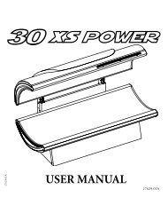
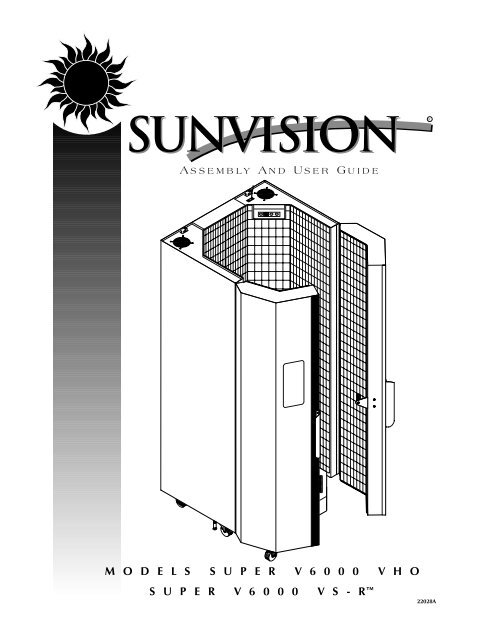
A SSEMBLY A ND U SER G UIDE<br />
M O D E L S S U P E R V 6 0 0 0 V H O<br />
S U P E R V 6 0 0 0 V S - R<br />
R<br />
22028A
Limited Lifetime Warranty<br />
SUNVISION ® warrants your tanning unit to be free of structural defects in its material and workmanship,<br />
under normal use, for its lifetime. SUNVISION will repair or replace, at their discretion, any<br />
defect to the structure which affects the performance of the unit.<br />
For 6 months from the date of purchase, SUNVISION will provide replacements for parts that prove<br />
to be defective in material or workmanship. Acrylic shields, fluorescent lamps, and lamp starters are<br />
excluded from this warranty. Labor will be covered for 30 days from purchase date. Normal wear,<br />
damage from misuse or abuse, damage incurred in transit, or damage done by unauthorized repairs<br />
or modifications are not covered by this warranty.<br />
ETS, Inc. disclaims any implied warranty of merchantability or fitness for any period beyond the<br />
expressed warranty. Some states do not allow limitations on how long an implied warranty lasts, so<br />
the above limitations may not apply to you.<br />
No one has authority to change or modify this Limited Lifetime Warranty in any respect. To obtain<br />
service under the Limited Lifetime Warranty, contact ETS, Inc. at 1-800-228-6292, and ask for the<br />
Technical Service Department.<br />
ETS, Inc. SHALL NOT BE LIABLE FOR LOSS OF USE, LOSS OF TIME , INCONVENIENCE, RENTAL OR<br />
SUBSTITUTE PRODUCTS, LOSS OF BUSINESS, LOSS OF INCOME, OR ANY OTHER INCIDENTAL OR<br />
CONSEQUENTIAL DAMAGES. Some states do not allow the exclusion or limitation of incidental or<br />
consequential damages, so the above limitation or exclusion may not apply to you.<br />
This warranty gives you specific legal rights, and you may also have other rights which<br />
may vary from state to state.<br />
All warranty service must be performed by an authorized service person. If your tanning unit must<br />
be returned for service, all freight charges must be at your expense. Contact your place of purchase<br />
for the address of the SUNVISION Service Center nearest you. Proof of purchase is required to<br />
obtain warranty service.<br />
This warranty covers the original purchaser only. This warranty is void if the unit is modified<br />
in any manner from its original design.
Welcome<br />
Congratulations on your purchase of this technologically advanced sun tanning unit.<br />
It has been designed to provide years of dependable service for you.<br />
Please read all the instructions in this booklet before installing and using the unit.<br />
Always be sure to observe all safety precautions.<br />
Contents<br />
Safety Information . . . . . . . . . . . . . . . . . . . . . . . . . . . . . . . .iii<br />
Installation . . . . . . . . . . . . . . . . . . . . . . . . . . . . . . . . . . . . . .1<br />
Unpacking and Inspection . . . . . . . . . . . . . . . . . . . . . . .1<br />
Tools Required . . . . . . . . . . . . . . . . . . . . . . . . . . . . . . . .1<br />
Pre-Installation Planning . . . . . . . . . . . . . . . . . . . . . . . . .2<br />
Assembly Procedures . . . . . . . . . . . . . . . . . . . . . . . . . . .3<br />
Bypass Plug . . . . . . . . . . . . . . . . . . . . . . . . . . . . . . . . . .5<br />
Remote Connections . . . . . . . . . . . . . . . . . . . . . . . . . . .6<br />
Operation . . . . . . . . . . . . . . . . . . . . . . . . . . . . . . . . . . . . . . .8<br />
Before You Tan . . . . . . . . . . . . . . . . . . . . . . . . . . . . . . . .8<br />
Exposure Times . . . . . . . . . . . . . . . . . . . . . . . . . . . . . . .8<br />
Using Your Booth . . . . . . . . . . . . . . . . . . . . . . . . . . . . . .9<br />
Care and Maintenance . . . . . . . . . . . . . . . . . . . . . . . . . . . .11<br />
Cleaning After Use . . . . . . . . . . . . . . . . . . . . . . . . . . . .11<br />
Thorough Periodic Cleaning . . . . . . . . . . . . . . . . . . . . .11<br />
Mechanical Inspection . . . . . . . . . . . . . . . . . . . . . . . . .11<br />
Replacing Lamps . . . . . . . . . . . . . . . . . . . . . . . . . . . . .12<br />
Troubleshooting . . . . . . . . . . . . . . . . . . . . . . . . . . . . . . . . .13<br />
Obtaining Service . . . . . . . . . . . . . . . . . . . . . . . . . .back cover<br />
ii
safety<br />
Information<br />
LABELING NOTICE: Labels are affixed on all systems to inform the user of possible dangers. Regulations are stated in<br />
21 CFR, Section 1040.20, and require that all products manufactured after September 8, 1986 which use sunlamps<br />
must display the following:<br />
AD<br />
Ultraviolet radiation. Follow instructions. Avoid overexposure. As with natural sunlight, overexposure<br />
can cause eye and skin injury and allergic reactions. Repeated exposure may cause premature<br />
aging of the skin and skin cancer. WEAR PROTECTIVE EYEWEAR; FAILURE TO MAY RESULT IN SEVERE BURNS<br />
OR LONGTERM INJURY TO THE EYES.<br />
Medications or cosmetics may increase your sensitivity to the ultraviolet radiation. Consult physician before using<br />
sunlamp if you are using medications or have a history of skin problems or believe yourself especially sensitive to<br />
sunlight. If you do not tan in the sun, you are unlikely to tan from the use of this product.<br />
Do not use without wire grid in place. <strong>Tanning</strong> normally appears after the first few sessions and maximizes after<br />
approximately four weeks. Tan once or twice per week thereafter to maintain appearance. Frequency of sessions<br />
should be limited to every other day. Persons already having a base tan may begin at advanced levels corresponding<br />
to the extent of their base tan.<br />
R E C O M M E N D E D E X P O S U R E T I M E S I N M I N U T E S<br />
M A X I M U M<br />
E X P O S U R E T I M E I S 1 0<br />
M I N U T E S<br />
Skin Type: Week # Week 1 Week 2 Week 3 Week 4 Subsequent<br />
New lamps emit approximately 20% more ultraviolet radiation during the first 50 hours of operation. Recommended<br />
tanning times should therefore be reduced by approximately 20% during that period.<br />
For a uniform tan, center yourself within the booth both front and back and to the left and right. This will result in<br />
your body being equidistant from all lamps. Other postions may result in over exposure to parts of your body.<br />
Use only the lamp listed below or certified equivalents as failure to will result in non-compliance with federal regulations.<br />
ACCELERATOR® VS-R Wolff® Model VAC75-T12-160W VS-R Bi-Pin<br />
ACCELERATOR® VHO Wolff® Model ACC75-T12-160W VHO PREHEAT BI-PIN<br />
Provided eyeshields (Lucas Products Super Sunnies or Intrexco No. 5635/1) or equivalent eyewear as defined under<br />
21 CFR 1040.20. Other types of eyewear may not provide adequate protection. Disconnect power before<br />
attempting to clean, relamp, or engage in the maintenance of this product.<br />
THIS EQUIPMENT MUST BE EARTH GROUNDED. THIS PRODUCT IS IN CONFORMITY WITH PERFORMANCE STANDARDS<br />
FOR SUN LAMP PRODUCTS UNDER 21 CFR<br />
PART 1040.20<br />
iii
Installation<br />
Unpacking and Inspection<br />
When removing the unit from its carton,<br />
always have two people available to<br />
help. We suggest having a moving dolly<br />
available to facilitate moving the unit<br />
into place.<br />
After unpacking the unit, inspect it for<br />
any visible damage. Report the extent of<br />
any damage to the transportation company.<br />
Also, within the same package you<br />
found this manual you should have also<br />
received a pair of goggles, the outside<br />
door handles (to be installed later), a<br />
hardware packet and a complimentary<br />
start-up kit.<br />
Record the serial number of the booth in<br />
the area provided on the back of this<br />
manual. This information will be required<br />
whenever you call customer service.<br />
Tools Required<br />
You will need the following tools to<br />
assemble your booth:<br />
#2 Phillips Screw Driver<br />
Adjustable Wrench<br />
Knife (Utility or similar)<br />
1/2” Wrench<br />
1
Installation-Pre-Installation Planning<br />
Pre-Installation Planning<br />
Before you begin to assemble your booth, you should observe the following preinstallation<br />
considerations.<br />
2<br />
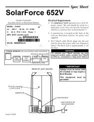
• Your booth operates from a 220V AC<br />
source. The unit must be hardwired<br />
to a dedicated circuit capable of providing<br />
60 amp service. Electrical<br />
connection of this unit requires a<br />
professional electrician.<br />
• IMPORTANT! Use of a voltage source<br />
above 230V AC may prevent proper<br />
operation of the booth and could<br />
cause damage and void the warranty.<br />
• Make sure the room in which you<br />
intend to use your booth is well ventilated.<br />
Air from the room is used to cool<br />
the booth, and a poorly ventilated<br />
room may cause the unit to become<br />
hot and cause discomfort to the user.<br />
• Your sunbed is designed to operate in<br />
an ambient room temperature of 80°F<br />
maximum and 70% relative humidity.<br />
• The SUNVISION ® Super V6000 must<br />
be installed in a room with a minimum<br />
ceiling height of eight (8) feet.<br />
Place your booth no closer than 6"<br />
from any wall.<br />
• Proper assembly of your booth<br />
requires three people. Plan to have a<br />
couple of helpers assist you.
Assembly<br />
1. Each of the unit’s halves should be<br />
placed together at the desired installation<br />
location. Align the holes (A), located<br />
at the top and bottom of the unit.<br />
You will need both wrenches for the<br />
next step.<br />
B<br />
A<br />
C<br />
Installation-Assembly<br />
2. Secure the two halves of the unit to<br />
one another using the four 5/16x3/4”<br />
Hex Head bolts (B) and four lock nuts<br />
(C). Do not tighten them fully at this<br />
time. NOTE: You may only be able to<br />
install three of the four bolts with the<br />
shipping brackets in place.<br />
3. Remove the two shipping brackets,<br />
located on the top of the booth, which<br />
connect the doors to the rear of the<br />
frame.<br />
3
Installation-Assembly<br />
4<br />
F<br />
E<br />
4. Lower all six of the leveling posts (A) until the<br />
weight is almost completely removed from the<br />
casters (B). Check the doors to see if the tops of<br />
the doors are level with each other when closed,<br />
it may be necessary to further adjust the levelers.<br />
After the unit is level tighten the nuts left loose<br />
from Step 1. If necessary adjust the casters under<br />
the doors (C). The door casters should bear only<br />
the weight of the doors. When properly adjusted<br />
the doors will open and close easily. There should<br />
be no gap between the doors when closed.<br />
5. Connect the electrical cable at the rear top of the<br />
unit. Slide the black split grommet (D) found in the<br />
accessory kit around the wire assembly and then<br />
press the grommet into slot (E). Now mount the<br />
white metal cap (F) cover over the connection with<br />
two #8x5/16” Phillips screws. Be careful not to<br />
crimp, bind or pinch any of the wires.<br />
A<br />
B<br />
D<br />
C<br />
G<br />
6. Attach the exterior handles to the doors<br />
using the pre-installed screws (G).<br />
C
7. Place the black, fan pedestal inside<br />
the unit oriented so that the side without<br />
the air register is toward the<br />
front. Connect the pedestal<br />
power plug to the receptacle<br />
located underneath the rear<br />
corner of the booth, next to the<br />
main power cord.<br />
Bypass Plug<br />
Connect the remote control bypass plug<br />
(A) to the remote control port (B) on top<br />
of your booth. The bypass plug can be<br />
inserted into either port. Your booth will<br />
not operate without the bypass plug or a<br />
remote system connected.<br />
NOTE: Your sunbed is designed to<br />
accept an input from a remote control<br />
B<br />
Installation- Bypass Plug<br />
device. The remote control is optional.<br />
If you plan on using a remote system<br />
refer to “Remote Connections”.<br />
CAUTION: Although the Remote<br />
Control Bypass plug provided with your<br />
sunbed will work wherever a T-Max®<br />
terminator is called for in the series,<br />
the T-Max® terminator will not work as<br />
a bypass plug. A bypass plug is needed<br />
only when your sunbed is operated<br />
without a remote system connected.<br />
The booth is equipped with two 8Ω<br />
speakers for your listening pleasure,<br />
capable of handling<br />
10W. Connect them to<br />
an external amplifier<br />
using the spring connectors<br />
(C) located at<br />
the top of the booth.<br />
5
Installation–Remote Connections<br />
Remote Connections<br />
Your booth incorporates advanced circuitry<br />
allowing it to connect and communicate with<br />
most remote control systems. If a remote system<br />
is to be used, first determine whether the<br />
remote system is a T-Max ® System or a standard<br />
remote system operating with a control<br />
relay. Follow the appropriate instructions for<br />
your system type.<br />
Warning: The remote connection is not<br />
designed to supply or accept high voltage,<br />
nor can it provide power to an external timer.<br />
The booth’s remote interface circuitry operates<br />
on 5 volts, attempting to connect it to<br />
any higher voltages will damage the booth as<br />
well as void your warranty.<br />
T-Max ® Manager Remote System<br />
The T-Max ® Manager remote system offers<br />
the ultimate in solarium control, while allowing<br />
the tanner easy straightforward operation.<br />
This system is ideal for multiple unit installations.<br />
Your booth is already configured to<br />
directly connect to this system. The circuitry<br />
inside your booth eliminates the need for the<br />
T-Max ® 1A when connecting to the T-Max ®<br />
Manager series. To connect your booth to this<br />
system follow the instructions that came with<br />
your remote system, noting figure 2 on the<br />
next page. After you have set the address, or<br />
“id” of each solarium, simply connect the RJ-<br />
22 Modular cable(s), described in the T-Max ®<br />
Manager manual, directly into the port(s)<br />
located on the back of your booth. You can<br />
place your booth at any location in the series.<br />
Remember the last connection in the series<br />
requires a T-Max ® terminator plug or SUNVI-<br />
SIONTM bypass plug.<br />
6<br />
T-Max ® 1A Remote System<br />
The T-Max ® 1A offers the same control as the<br />
T-Max ® Manager in single booth installations.<br />
For this, your 1A must be configured as a<br />
“master”. If the 1A is not configured as a master<br />
it will not work in this application.<br />
After you have set the address, or “id”, on the<br />
T-Max ® 1A and the booth simply connect the<br />
RJ-22 modular cables, described in the T-<br />
Max ® user’s guide, directly into either port<br />
located on the top of the booth and either<br />
port on the back of the T-Max ® 1A. If the T-<br />
Max ® 1A and the booth are more than 100<br />
feet apart, terminators or SUNVISION ®<br />
Remote Bypass plugs should be installed in<br />
the unused ports. See figure 1.<br />
Setting the address<br />
Before connecting your booth to the T-Max ®<br />
Manager or T-Max ® 1A, the address or “id” of<br />
your booth must first be set. The autoaddressing<br />
feature of the latest T-Max ®<br />
Manager models is not compatible with this<br />
booth. Set the “id” manually as described<br />
below.<br />
Setting the “id”<br />
1. Verify that the booth display is indicating<br />
a “0”.<br />
2. Press and hold the stop button located<br />
on the booth display for three seconds<br />
and release. The display should indicate<br />
an “id” number from 1 to 99.<br />
3. If you are using a T-Max ® 1A as your<br />
remote the “id” of the booth must be<br />
set to “1”. If you are using a T-Max ®<br />
Manager each solarium must be<br />
assigned a different “id”. To set the<br />
“id” press the timer button until the<br />
desired number is achieved.
4. Press the stop button to return to the<br />
normal display mode.<br />
5. If you are using a T-Max ® 1A its “id”<br />
must be set to “0.0”. See your 1A manual<br />
for instructions. Also refer to your T-<br />
Max ® 1A or Manager manuals to set<br />
other functions such as delay time and<br />
number of solariums in the T-Max ®<br />
Manager series.<br />
Figure 1<br />
Figure 2<br />
Figure 3<br />
Installation–Remote Connections<br />
Remote systems using a Control Relay<br />
Most non-T-Max ® remote systems control the<br />
booth by the use of a relay. The relay operates<br />
the booth by connecting and disconnecting<br />
a pair of wires leading from the booth.<br />
Refer to the user’s manual provided with your<br />
remote system to determine if it operates in<br />
this way. To connect your booth to this type<br />
of system a remote interface kit is required.<br />
Call ETS at the phone number listed on the<br />
back of this guide to obtain the kit. Figure 3<br />
below details a typical connection. Follow the<br />
instructions provided with the kit and from<br />
the remote’s manual to make the necessary<br />
connections.<br />
If you have questions consult the<br />
Troubleshooting guide in this manual or call<br />
ETS at the phone number listed on the back<br />
of this guide.<br />
7
Operation<br />
Before You Tan<br />
Before using your booth, please note the<br />
following important precautions:<br />
8<br />
• WARNING your booth is designed for<br />
individual use. Only one pair of protective<br />
goggles is provided. Always<br />
wear these or another approved pair<br />
of goggles. Regular sunglasses do not<br />
provide adequate protection from<br />
ultraviolet light. You should never<br />
look at the lamps when turned on<br />
without wearing the appropriate protective<br />
goggles.<br />
• Some medication may increase your<br />
sensitivity to ultraviolet light. It is recommended<br />
that you consult a physician<br />
before using this booth if taking<br />
any medication or if you suspect that<br />
your skin might be especially sensitive<br />
to sunlight. Included with this manual<br />
is an FDA booklet on medications that<br />
increase sensitivity to light.<br />
• As with all electrical appliances, do<br />
not operate this device near water<br />
or while you are wet.<br />
Exposure Times<br />
We recommend that you tan every other<br />
day, following the tanning times in the<br />
exposure schedule. <strong>Tanning</strong> normally<br />
appears after the first few sessions and<br />
maximizes after approximately four<br />
weeks. Tan once or twice per week thereafter<br />
to maintain appearance. Persons<br />
already having a base tan may begin at<br />
advanced levels corresponding to the<br />
extent of their base tan.<br />
Follow the guidelines for skin type and<br />
exposure times as shown in the table<br />
below.<br />
RECOMMENDED EXPOSURE TIMES IN MINUTES MAXIMUM EXPOSURE TIME IS 10 MINUTES<br />
Skin Type: Week # Week 1 Week 2 Week 3 Week 4 Subsequent<br />
Session # 1st-3rd 4th-6th 7th-10th 11th-13th Maximum<br />
I Sensitive Skin (Burns easily and severely and does not tan.) NOT RECOMMENDED FOR TANNING<br />
II Light (Burns easily and severely and tans minimally.) 2 4 6 8 10<br />
III Normal (Burns moderately and tans average.) 3 5 7 10 10<br />
IV Dark (Burns minimally, tans easily and above average.) 4 6 8 10 10
Using Your Booth<br />
When connected to the T-Max ® Manager or T-Max ® 1A<br />
A Body fan control - Turns body fan on or off.<br />
B Body fan indicator - Indicates fan operation.<br />
(ON/OFF)<br />
C Timer display - Displays remaining time.<br />
D Stop button - Turns booth off.<br />
A B C D E<br />
E Timer button - Turns booth on. Timer display<br />
shows remaining time. If a lesser<br />
time is desired, repeatedly press timer<br />
button until desired time is displayed.<br />
Operation-Using Your Booth<br />
1. Enter the booth and shut the doors behind<br />
you. Center yourself on the pedestal for<br />
even tanning.<br />
2. Assuming the remote system has been set to<br />
allow a pre-tanning delay time, the timer<br />
display (C) will repeatedly flash the delay<br />
symbol “dL” and then the remaining delay<br />
time. Press the timer button (E) or wait until<br />
the delay time has expired to begin the tanning<br />
session. The lamps and body fan will<br />
turn on and the timer will begin to count<br />
down. If the timer did not display a “dL”, see<br />
Troubleshooting.<br />
3. If a tanning time less than the displayed<br />
time is desired repeatedly press the timer<br />
button (E) to decrease the remaining time.<br />
4. When the timer reaches 0 the lamps turn<br />
off. If you want to stop your session before<br />
time expires press the stop button (D).<br />
5. Exit the booth when the tanning session is<br />
over. The body fan runs for 3 minutes after<br />
the lamps shut off to aid in cooling the<br />
booth. The timer will indicate “. .”, this is<br />
a reminder to clean the booth. After the<br />
booth is cleaned press the timer button and<br />
the display will return to “0”.<br />
9
Operation-Using Your Booth<br />
Using Your Booth<br />
When configured as a stand alone unit or<br />
when connected to a remote system using a<br />
control relay.<br />
10<br />
If your booth is connected to a T-Max ®<br />
Manager remote system, see Using Your<br />
Booth When connected to the T-Max ®<br />
Manager, previous page.<br />
A B C D E<br />
A Body fan control - Turns body fan on or off.<br />
B Body fan indicator - Indicates fan operation.<br />
(ON/OFF)<br />
C Timer display - Displays remaining time.<br />
D Stop button - Turns booth off.<br />
E Timer button - Turns booth on. Timer display<br />
shows remaining time. If a lesser<br />
time is desired, repeatedly press timer<br />
button until desired time is displayed.<br />
1. Enter the booth and shut the doors behind<br />
you. Center yourself on the pedestal for<br />
even tanning.<br />
2. Start the booth by pressing the timer button<br />
(E), located at the top of the canopy. The<br />
lamps and body fan will turn on and the<br />
timer display (C) will indicate the session<br />
time remaining. If less than the maximum<br />
tanning time is desired, repeatedly press<br />
the timer button (E) until the desired time is<br />
indicated.<br />
3. When the timer reaches 0, the lamps will<br />
turn off. If you want to stop your session<br />
before time expires press the stop button<br />
(D). The timer will then allow you ten seconds<br />
to reactivate the booth with the<br />
unused time. After ten seconds the timer<br />
system resets back to 0 minutes.<br />
4. Exit the booth when the tanning session is<br />
over. The cooling fans run for 3 minutes<br />
after the lamps shut off to aid in cooling the<br />
booth.
Care<br />
& Maintenance<br />
Introduction<br />
Your tanning booth has an hour meter<br />
which keeps track of how many hours the<br />
booth has been in operation. Use this<br />
meter to determine when your booth<br />
requires maintenance.<br />
Cleaning After Use<br />
Clean and disinfect your tanning booth’s<br />
pedestal, handles, control console and wire<br />
grid after each use. Use a non-abrasive disinfectant<br />
cleaner. We recommend<br />
SunQuest ® disinfectant. Spray a clean soft<br />
cloth with disinfectant and then clean all<br />
surfaces that the tanner may have come in<br />
contact with.<br />
Thorough Periodic Cleaning<br />
Introduction<br />
The cooling fans draw air through the<br />
booth and over time will cause a dust<br />
buildup on the lamps and reflectors. This<br />
will reduce the tanning effectiveness of the<br />
booth. When a dust buildup is observed, it<br />
is necessary to thoroughly clean the inside<br />
of the booth.<br />
Warning! Disconnect booth from electrical<br />
power before cleaning.<br />
Cleaning the Booth<br />
Step 1. Remove the wire grids and lamps<br />
as described in Replacing Lamps.<br />
Step 2. With a soft cloth, wipe the entire<br />
length of each lamp and reflector<br />
to remove any film buildup.<br />
Step 3. Re-install the lamps and wire grids<br />
as described in Replacing Lamps.<br />
Mechanical Inspection<br />
Your tanning booth has been built for years<br />
of service. To ensure trouble free operation<br />
throughout its life, inspect the unit’s<br />
mechanical integrity every 400-500 hours<br />
of use.<br />
• Inspect the unit’s fasteners verifying<br />
that all are firmly in place. Pay particular<br />
attention to the door alignment.<br />
Adjust the door casters as needed. See<br />
Assembly Step 2.<br />
• Inspect the AC power cable and its connections.<br />
11
Care & Maintenance-Replacing Lamps<br />
Replacing Lamps<br />
To be assured of maximum tanning effectiveness,<br />
change lamps after approximately<br />
800-1000 hours of use. <strong>Tanning</strong><br />
will continue after this time but at a slower<br />
rate. To ensure trouble-free operation<br />
of your sunbed, replace the lamp starters<br />
whenever the lamps are replaced.<br />
Warning! Disconnect the booth from<br />
electrical power before servicing.<br />
Removing/Replacing Wire Grids<br />
The wire grids in the booth are secured in<br />
place by screws. Remove these screws,<br />
located at the top of the grid, and lift the<br />
grid out of its lower slot. The inside handle<br />
on the door must also be removed<br />
before removing the door grid. Simply<br />
unscrew the handle from the handle<br />
bracket as shown. After changing lamps,<br />
replace the grids, handles and screws.<br />
When replacing the door grid, be sure to<br />
position the grid behind the retaining pin<br />
on the handle bracket to limit movement.<br />
Removing/Replacing Lamps<br />
After grids are removed, replace lamps as<br />
follows:<br />
Step 1. Grasp the lamp at one end and<br />
at the middle, then turn the<br />
lamp a quarter turn. The lamp<br />
may then be gently removed<br />
from its holder.<br />
Step 2. To re-install a lamp, insert the<br />
pins located on the ends of the<br />
lamp into the slots on top of the<br />
lamp holder and turn the lamp a<br />
quarter turn.<br />
12<br />
Recommended Replacement Lamps<br />
We recommend using the lamps specified<br />
below. Use of uncertified lamps is a<br />
violation of federal regulations and will<br />
void your warranty. These lamps have an<br />
average life of 800-1000 hours of effective<br />
tanning use. Lamps used longer than<br />
that begin to lose their effectiveness even<br />
though they will continue to light.<br />
Only the following lamp type has been<br />
certified for use in your SUNVISION ®<br />
booth:<br />
ACCELERATOR ® VS-R Wolff ®<br />
Model VAC75-T12-160W VS-R Bi-Pin<br />
ACCELERATOR ® VHO Wolff ®<br />
Model ACC75-T12-160W VHO PREHEAT BI-PIN
Troubleshooting<br />
Problem<br />
Booth not tanning<br />
Lamps fail to light and timer<br />
display is blank<br />
Timer display changes to indicate<br />
a tanning time after the<br />
timer button is pressed but<br />
lamps do not come on<br />
My booth is connected to the<br />
T-Max ® Manager remote system<br />
and when the delay time<br />
has expired the timer display<br />
starts counting down but the<br />
bed lights do not come on<br />
My booth won’t work with<br />
the T-max ® Manager remote<br />
systems<br />
Timer display continues to<br />
show a 0 after the timer button<br />
is pressed<br />
The last minute of tanning<br />
time does not count down<br />
from 59 seconds, but some<br />
time less than 59 seconds<br />
Solution<br />
1. Clean booth, see Thorough Periodic Cleaning.<br />
2. Ensure supply voltage is between 208 and 230V AC.<br />
3. Replace lamps if lamp hours are greater than 800hrs.<br />
1. Make sure the unit is connected to a power source.<br />
2. Check source of AC power. Reset circuit breaker or<br />
replace fuse.<br />
1. Bypass plug is not installed see Bypass Plug.<br />
2. A non-SUNVISION ® bypass has been used. See Bypass<br />
Plug.<br />
3. If remote is being used, other than T-Max ® Manager,<br />
the external timer may not be activated, or...<br />
4. remote wiring is incorrect, see the instructions provided<br />
with the remote interface kit.<br />
The auto start feature of the remote system is disabled,<br />
see the instructions provided with your remote system.<br />
1. The booth must first be set to a unique address see<br />
Remote Connections.<br />
2. The bypass or terminator plug may be installed in the<br />
series in an inappropriate location. Plug the bypass<br />
plug only into the unit at the end of the series.<br />
1. T-Max ® Manager remote system has not yet been set.<br />
2. booth address is not set correctly see Remote<br />
Connections.<br />
If the timer button has been pressed to decrease tanning<br />
time during the session, the time expired in the<br />
current minute is subtracted from the last minute.<br />
13
Troubleshooting-Problem/Solution Chart<br />
One or more lamps fail to light<br />
My bed is connected to a T-<br />
Max ® remote system but I am<br />
having trouble getting into “id”<br />
mode.<br />
My bed, connected to a T-<br />
Max ® Manager, did not display<br />
“dL” but does indicate:<br />
“0”.<br />
a tanning time and the<br />
lamps have come on.<br />
a tanning time but the<br />
lamps have not come on.<br />
Timer display is indicating Er 1<br />
Timer display is indicating Er 2<br />
Timer display is indicating Er 3<br />
Timer display is indicating Er 4<br />
Timer display is indicating Er 5<br />
Timer display is indicating Er 6<br />
14<br />
Problem<br />
Solution<br />
1. Check that lamp is installed correctly.<br />
2. Switch unlit lamp with a lamp that lights, if new lamp<br />
lights and old lamp still does not, replace old lamp.<br />
You have probably attempted to connect your sunbed<br />
to the remote system already. Disconnect the remote<br />
plug(s) from the ports at the back of the sunbed, wait<br />
90 seconds and try again.<br />
1. Remote device has not been set.<br />
2. The sunbed has not been connected to the remote<br />
system, see Remote Connections.<br />
1. Delay time of T-Max ® Manager has not been set.<br />
2. Delay time has expired and session has begun.<br />
Auto start function of T-Max ® Manager has been<br />
turned off. Press the timer button to turn on lamps<br />
Body lamps are on when they should be off, have<br />
service technician check the contactor.<br />
Body lamps are off when they should be on, have<br />
servicer check contactor and its wiring from the main<br />
timer box.<br />
Bench lamps are on when they should be off, have<br />
service technician check the contactor.<br />
Bench lamps are off when they should be on, have<br />
service technician check the contactor and its wiring<br />
from the main timer box.<br />
Not currently used<br />
Not currently used
Problem<br />
Timer display is indicating Er 7<br />
Timer display is indicating Er 8<br />
Timer display is indicating Er 9<br />
Timer display is indicating Er 10<br />
Timer display is indicating Er 11<br />
Timer display is indicating Er 12<br />
Timer display is indicating Er 13<br />
Timer display is indicating Er 14<br />
Timer display is indicating Er 15<br />
Solution<br />
Face Tanner contactor is closed when it should be<br />
open, have service technician check the contactor.<br />
Face Tanner contactor is open when it should be<br />
closed, have service technician check the contactor<br />
and its wiring from the main timer box.<br />
Ballast Drawer is open or drawer switch is broken.<br />
Timer computer is in an illegal state, reset power to<br />
correct, replace main timer if error reoccurs.<br />
Timer computer is in an illegal state, reset power to<br />
correct, replace main timer if error reoccurs.<br />
Timer computer is in an illegal state, reset power to<br />
correct, replace main timer if error reoccurs.<br />
Timer computer is in an illegal state, reset power to<br />
correct, replace main timer if error reoccurs.<br />
The timer display is not responding;<br />
1. Check cable to display.<br />
2. Replace display assembly.<br />
3. Replace main timer box.<br />
Troubleshooting-Problem/Solution Chart<br />
Timer computer is in an illegal state, reset power to<br />
correct, replace main timer if error reoccurs.<br />
15
CALL FOR SERVICE OR<br />
QUESTIONS:<br />
1•800•228•6292<br />
6270 Corporate Drive<br />
Indianapolis, IN 46278-2900<br />
Have the following information ready<br />
when calling ETS to order parts or service<br />
for your bed:<br />
Date Purchased<br />
Canopy Serial Number<br />
Bench Serial Number