Installation Note - Tii Network Technologies
Installation Note - Tii Network Technologies
Installation Note - Tii Network Technologies

Create successful ePaper yourself
Turn your PDF publications into a flip-book with our unique Google optimized e-Paper software.
P/N 92233001 • Rev A• 1/20/2009<br />
Warranty: If this unit fails during the warranty period, contact tii customer service to authorize return. Unit may be returned prepaid.<br />
141 Rodeo Drive<br />
Edgewood, NY 11717<br />
Toll Free 888.444.4720<br />
www.tiinettech.com<br />
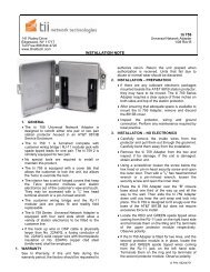
Model 95S-2-00-0<br />
Sealed Subscriber Bridge<br />
Module with RJ-45 Test Receptacle<br />
Description<br />
1. The tii 95S-2-00-0 Sealed Subscriber Bridge<br />
Module with RJ-45 Test Receptacle maintains<br />
a constant direct connection between<br />
customer and central office service provider.<br />
The Bridge is equipped with a test jack and<br />
IDC terminations (see figure 1). The test jack<br />
is provided as an access for test equipment to<br />
assure a signal is being received and<br />
transmitted properly.<br />
Features<br />
Figure 1<br />
<strong>Installation</strong> <strong>Note</strong><br />
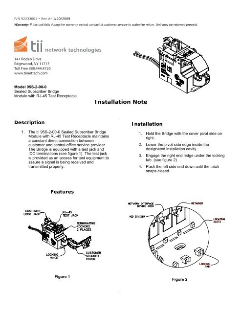
<strong>Installation</strong><br />
1. Hold the Bridge with the cover pivot side on<br />
right.<br />
2. Lower the pivot side edge inside the<br />
designated installation cavity.<br />
3. Engage the right end ledge under the locking<br />
tab. (see figure 2)<br />
4. Push the left side end down until the latch<br />
snaps closed.<br />
Figure 2
Wiring<br />
1. The receive and transmit pairs are connected<br />
to the Bridge. Customer has the option of<br />
installing a #10 Master lock around the<br />
customer lock hasp (see figure 1).<br />
2. Do not strip wire insulation from wires to be<br />
terminated to Bridge.<br />
3. Dress terminating wires (to protector) over NID<br />
divider (see figure 2).<br />
4. Open customer security cover on Bridge.<br />
5. Lift both Bridge rockers to the full up position<br />
as shown (see figure 3).<br />
6. Dress wires around security cover.<br />
7. Hold the customer receive pair wires between<br />
thumb and index finger (approx 1/8”<br />
separation between wires).<br />
NOTE: Wires should be aligned to the<br />
corresponding holes.<br />
8. Insert wires into wire guides at the same time<br />
until they bottom out.<br />
9. While holding wires in wire guides, terminate<br />
rocker with thumb (lower rocker all the way).<br />
10. Terminate transmit pair to rocker.<br />
11. Assure both rockers are in the down position<br />
and close customer security cover.<br />
Figure 3<br />
Signal Testing<br />
1. Open customer security cover.<br />
2. Using a portable data test set, insert dataline RJ-45 plug<br />
into customer test jack (see figure 3).<br />
3. Verify that the portable data test set is able to<br />
communicate with central office.