Lossnay ERV - MyLinkDrive
Lossnay ERV - MyLinkDrive
Lossnay ERV - MyLinkDrive

Create successful ePaper yourself
Turn your PDF publications into a flip-book with our unique Google optimized e-Paper software.
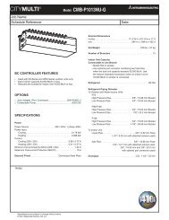
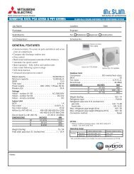
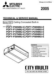
LGH-F-RX3-E<br />
1. COMPARISON OF PRIMARY BUILDING VENTILATION METHODS ....................................................................<strong>ERV</strong>-2<br />
2. LOSSNAY ® PRINCIPLES.........................................................................................................................................<strong>ERV</strong>-2<br />
2.1. LOSSNAY ® ENERGY RECOVERY VENTILATIORS - CORE .........................................................................<strong>ERV</strong>-2<br />
2.2. LOSSNAY ® CONSTRUCTION ........................................................................................................................<strong>ERV</strong>-3<br />
2.3. CALCULATION OF TOTAL ENERGY RECOVERY EFFICIENCY ..................................................................<strong>ERV</strong>-3<br />
2.4. UNBALANCED AIRFLOW CORRECTION .....................................................................................................<strong>ERV</strong>-4<br />
2.5. LOSSNAY ® OPERATION / VENTILATION MODES ........................................................................................<strong>ERV</strong>-4<br />
2.6. AUTOMATIC VENTILATION SWITCHING - BYPASS DAMPER OPERATION ..............................................<strong>ERV</strong>-5<br />
2.7. IMPORTANCE OF FILTERS ...........................................................................................................................<strong>ERV</strong>-5<br />
2.8. ENERGY RECOVERY VENTILATION TERMINOLOGY ................................................................................<strong>ERV</strong>-7<br />
3. LOSSNAY ® MODELS AND SPECIFICATIONS ........................................................................................................<strong>ERV</strong>-8<br />
LGH-F300RX3-E .......................................................................................................................................................<strong>ERV</strong>-8<br />
LGH-F470RX3-E .....................................................................................................................................................<strong>ERV</strong>-10<br />
LGH-F600RX3-E .....................................................................................................................................................<strong>ERV</strong>-12<br />
LGH-F1200RX3-E ...................................................................................................................................................<strong>ERV</strong>-14<br />
4. WIRING DIAGRAMS ..............................................................................................................................................<strong>ERV</strong>-16<br />
5. SOUND ANALYSIS ................................................................................................................................................<strong>ERV</strong>-18<br />
5.1. SOUND ANALYSIS .......................................................................................................................................<strong>ERV</strong>-18<br />
5.2. LGH-F-RX3-E NC CURVES ..........................................................................................................................<strong>ERV</strong>-18<br />
6. FAN SPEED CONTROL CONSIDERATIONS........................................................................................................<strong>ERV</strong>-20<br />
7. INSTALLATION ......................................................................................................................................................<strong>ERV</strong>-20<br />
7.1. INSTALLATION DIAGRAMS .........................................................................................................................<strong>ERV</strong>-20<br />
7.2. ALTERNATE INSTALLATION FOR LOSSNAY ® ............................................................................................<strong>ERV</strong>-21<br />
7.3. SELECTING DUCT ATTACHMENT DIRECTION .........................................................................................<strong>ERV</strong>-22<br />
7.4. INSTALLATION OF SUPPLEMENTARY FAN DEVICES AFTER LOSSNAY ® UNIT .....................................<strong>ERV</strong>-23<br />
8. ELECTRICAL INSTALLATION ...............................................................................................................................<strong>ERV</strong>-23<br />
9. SYSTEM CONTROL EXAMPLES ..........................................................................................................................<strong>ERV</strong>-24<br />
LGH-F-RX3-E (Feb. 2009)<br />
Performance Certified<br />
to ARI 1060 Standard<br />
<strong>ERV</strong>-1<br />
<strong>Lossnay</strong> <strong>ERV</strong><br />
LGH-F-RX3-E
LGH-F-RX3-E<br />
1. COMPARISON OF PRIMARY BUILDING VENTILATION METHODS<br />
There are two main ventilation methods:<br />
Centralized Ventilation Method<br />
This is mainly used in large buildings, with the outside air<br />
intake being installed in one machine room. For this method,<br />
primary treatment of the outside air, such as energy recovery<br />
and dust removal, is performed before distribution to the building<br />
duct system.<br />
Air intake<br />
(outside air)<br />
Filters<br />
<strong>Lossnay</strong> ®<br />
Each unit<br />
Exhaust<br />
Air exhaust<br />
(stale air)<br />
Supply fan<br />
Independent Zoned Ventilation Method<br />
This is mainly used in small to medium-sized buildings,<br />
with areas being ventilated using outside air intakes from<br />
independent ventilation devices. The rate of use of this<br />
method has recently increased as zone conditioning and<br />
independent control have become more feasible.<br />
System operation with celiling cassette (recessed) air conditioner<br />
Ceiling-cassette package air<br />
conditioner or fan coil unit<br />
System operation with ducted air conditioner<br />
Independent operation with ceiling-suspended air conditioner<br />
Ceiling-cassette or ceiling-suspended-type<br />
package air conditioner or fan coil unit<br />
2.1. <strong>Lossnay</strong> ® 2. LOSSNAY<br />
Energy Recovery Ventilators – Core<br />
® PRINCIPLES<br />
Ceiling-embedded-type package<br />
air conditioner or fan coil unit<br />
Exhaust grill<br />
Exhaust grill<br />
Ceiling-recessed-type<br />
<strong>Lossnay</strong> ® unit<br />
Finished ceiling<br />
Exhaust air<br />
Outside air<br />
Ceiling-recessedtype<br />
<strong>Lossnay</strong> ®<br />
Finished ceiling<br />
Exhaust air<br />
Outside air<br />
Ceiling-mounted-type <strong>Lossnay</strong> or<br />
ceiling-embedded-type <strong>Lossnay</strong> ®<br />
Outside air<br />
Exhaust air<br />
Finished ceiling<br />
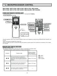
The sophisticated energy recovery technology of the LOSSNAY® core is constructed from a specially treated cellulose membrane<br />
separating cross-flow air passages with a corrugated structure for strength and durability. See below, right for an illustration of the<br />
LOSSNAY® core.<br />
32°F (0°C)<br />
Fresh cool air (outdoor)<br />
CITY MULTI® can integrate LOSSNAY® <strong>ERV</strong>s into the air conditioning system, providing the best overall solution to ventilation<br />
and air-conditioning.<br />
CENTRALIZED CONTROLLER AG-150A<br />
Centralized Controller<br />
AG-150A<br />
41°F (5.2°C)<br />
Stale hot air (exhaust)<br />
Outdoor unit<br />
59°F (14.8°C)<br />
Fresh warm air (indoor supply air)<br />
Remote controller<br />
68°F (20°C)<br />
Stale warm air (indoor air)<br />
Stale air exhaust<br />
(dirty indoor air)<br />
Indoor unit Indoor unit<br />
Fresh air induction<br />
(fresh air)<br />
<strong>Lossnay</strong>®<br />
Fresh air exhaust<br />
(fresh heating/cooling air)<br />
Stale air induction<br />
(dirty heating/cooling air)<br />
LOSSNAY ® Remote controller PZ-52SF-E<br />
Performance Certified<br />
to ARI 1060 Standard<br />
Lineup of LOSSNAY<br />
<strong>ERV</strong>-2<br />
LGH-F-RX3-E (Feb. 2009) LGH-F300RX3-E 300 cfm 1-phase, 208/230V, 60Hz<br />
LGH-F470RX3-E 470 cfm 1-phase, 208/230V, 60Hz<br />
LGH-F600RX3-E 600 cfm 1-phase, 208/230V, 60Hz<br />
® <strong>ERV</strong> units
CENTRALIZED CONTROLLER AG-150A<br />
Centralized Controller<br />
AG-150A<br />
Lineup of LOSSNAY ® <strong>ERV</strong> units<br />
2.3. Calculation of Total Energy Recovery Efficiency<br />
The <strong>Lossnay</strong> ® Core’s energy recovery efficiency can be considered using the following three transfer rates:<br />
1. Temperature (sensible heat) recovery efficiency<br />
2. Humidity (latent heat) recovery efficiency<br />
3. Enthalpy (total heat) recovery efficiency<br />
The energy recovery effect can be calculated if two of the<br />
above efficiencies are known. (<strong>Lossnay</strong> ® performance and<br />
cost analysis can also be determined using Mitsubishi Electric<br />
<strong>ERV</strong>alue ® software.<br />
• Each recovery efficiency can be calculated with the formulas<br />
in the table.<br />
• When the supply and exhaust air volumes are equal, the<br />
heat recovery efficiencies on the supply and exhaust sides<br />
are the same.<br />
• When the supply and exhaust air volumes are not equal, the<br />
total heat recovery efficiency is low if the exhaust volume is<br />
lower, and high if the exhaust volume is higher.<br />
EA<br />
Stale indoor<br />
air exhaust<br />
Transmission<br />
plates<br />
Item<br />
Temperature recovery<br />
efficiency (%)<br />
Formula<br />
tOA - tSA<br />
t = [ x 100<br />
tOA - tRA]<br />
= Efficiency (%)<br />
t = Dry Bulb<br />
Outside air intake<br />
OA<br />
Enthalpy recovery<br />
efficiency (%)<br />
iOA - iSA<br />
= iOA - iRA x 100<br />
Temperature (°F)<br />
i = Enthalpy (Btu/lb)<br />
i [ ]<br />
Remote controller<br />
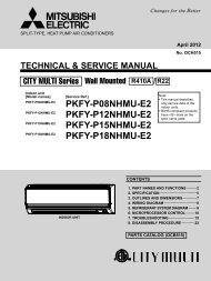
2.2. <strong>Lossnay</strong> ® Construction<br />
<strong>Lossnay</strong> ® <strong>ERV</strong>s are constructed so that the exhaust<br />
air passage from the indoor side to the outdoor<br />
side (RA EA) and the outside air passage from<br />
the outdoor side to the indoor side (OA SA)<br />
cross. The <strong>Lossnay</strong> ® energy recovery unit features<br />
the <strong>Lossnay</strong> ® Core, which is installed at this cross<br />
point and recovers the heat by conduction through<br />
the separating medium between the airflows,<br />
and latent energy by molecular transfer through<br />
the separation plate driven by vapor pressure<br />
differential between the airstreams. This enables<br />
the total energy loss during exhaust to be greatly<br />
reduced.<br />
Indoor unit Indoor unit<br />
LGH-F300RX3-E 300 cfm 1-phase, 208/230V, 60Hz<br />
LGH-F470RX3-E 470 cfm 1-phase, 208/230V, 60Hz<br />
LGH-F600RX3-E 600 cfm 1-phase, 208/230V, 60Hz<br />
LGH-F1200RX3-E 1200 cfm 1-phase, 208/230V, 60Hz<br />
SA<br />
(Supply air diffuser)<br />
Supply fan<br />
RA<br />
(Return air)<br />
Exhaust side filter<br />
OUTDOORS INDOORS<br />
LGH-F-RX3-E (Feb. 2009)<br />
<strong>Lossnay</strong>®<br />
LOSSNAY ® Remote controller PZ-52SF-E<br />
<strong>Lossnay</strong> ® Core<br />
<strong>ERV</strong><br />
EA<br />
(Exhaust air)<br />
Exhaust fan<br />
OA<br />
(Outside air)<br />
Intake side filter<br />
Note: The duct inlet and outlet are arranged in-line<br />
in the actual product.<br />
SA = Supply Air; RA = Return Air<br />
EA = Exhaust Air; OA = Outside Air<br />
SA<br />
Supply<br />
preconditioned<br />
outside air to<br />
AC system<br />
Partition plates<br />
Return stale indoor<br />
air<br />
RA<br />
Performance Certified<br />
to ARI 1060 Standard<br />
<strong>ERV</strong>-3<br />
<strong>Lossnay</strong> <strong>ERV</strong><br />
LGH-F-RX3-E
LGH-F-RX3-E<br />
Calculation of Supply Air Condition After Passing Through <strong>Lossnay</strong> ®<br />
If the <strong>Lossnay</strong> energy recovery efficiency and the conditions<br />
of the room and outdoor air are known, the conditions of the<br />
air entering the room and the air exhausted outdoors can be<br />
determined with the following formulas in the table.<br />
2.4. Unbalanced Airflow Correction<br />
In unbalanced applications, it is necessary to calculate the pressure<br />
drops of the two air streams separately using the applicable chart<br />
and correct the efficiencies using the instructions and the K-Factor<br />
chart below.<br />
1. In unbalanced airflow applications, the external<br />
static pressure must be calculated for each air stream<br />
separately using the ESP curves for the applicable<br />
product.<br />
2. The temperature effectiveness must also be<br />
corrected using the K-Factor chart (at right).<br />
A. Determine which correction factor to use by<br />
calculating the K-Factor (Air Volume Ratio).<br />
B. Determine the balanced airflow effectiveness<br />
from the applicable product graphs using the outside<br />
airflow (CFM).<br />
C. Correct the effectiveness for the unbalanced<br />
airflow by finding the Original Exchange Balanced<br />
Efficiency (%), then find the appropriate K-Factor<br />
Curve in the chart. From that point, read the<br />
Corrected Exchange Efficiency (%) on the left side of<br />
the chart.<br />
2.5. <strong>Lossnay</strong> ® Operation / Ventilation Modes<br />
1. Energy Recovery — Heat Exchange<br />
<strong>ERV</strong>-4<br />
LGH-F-RX3-E (Feb. 2009)<br />
Corrected Exchange Efficiency (%)<br />
Supply side Exhaust side<br />
Temperature tSA = tOA - (tOA- tRA) x t tEA = tRA + (tOA - tRA ) x t<br />
Enthalpy iSA = iOA - (iOA - i RA ) x i iEA = iRA + (i OA - i RA ) x i<br />
(K-Factor)<br />
Energy Recovery Efficiency Correction Curve<br />
Energy Recovery<br />
Efficiency (%)<br />
<strong>Lossnay</strong> ® technology is a full enthalpic energy exchange that recovers both<br />
sensible energy or “heat recovery” and latent energy or “moisture transfer”<br />
between air streams.<br />
100<br />
(K-Factor)<br />
Original Exchange Balanced Efficiency (%)<br />
2. Bypass — No Exchange 3. Automatic — Heat Exchange: Bypass<br />
• In cooling, the automatic mode<br />
accomplishes an energy savings function.<br />
When the inbound outside air is ≥7.2º F<br />
cooler than the outbound exhaust air, the<br />
bypass damper opens in the outbound<br />
airstream. This increases airflow and<br />
provides cooler air to the conditioned<br />
space.<br />
1.4<br />
1.1<br />
1.0<br />
0.9<br />
0.8<br />
0.7<br />
0.6<br />
0.5<br />
• In heating, the automatic mode<br />
may not be suitable without supply-air<br />
preheating.<br />
1.3<br />
1.2<br />
Performance Certified<br />
to ARI 1060 Standard
2.6. Automatic Ventilation Switching - Bypass Damper Operation<br />
Effect of Automatic Ventilation Mode<br />
The automatic damper mode automatically provides the correct ventilation for the conditions in the room. It eliminates the need for manual switch<br />
operations when setting the <strong>Lossnay</strong> ventilator to “bypass” ventilation. The following shows the effect “bypass” ventilation will have under various<br />
conditions. For automatic operation, when the air conditioning system is in the cooling mode, the bypass damper will open if the entering outside<br />
air temperature is 7.2°F or more lower than the exhaust air temperature.<br />
(1) Reduces cooling load--If the air outside is cooler than the air inside the building during the cooling season (such as early morning or at night),<br />
bypass ventilation will draw in the cooler outside air and reduce the cooling load on the system.<br />
(2) Cooling using outdoor air--During cooler season (such as between spring and summer or between summer and fall), if the people in a room<br />
cause the temperature of the room to rise, bypass ventilation will draw in the cool outside air and use it to cool the room.<br />
(3) Night purge--Bypass ventilation can be used to release hot air from inside the building that has accumulated during the hot summer season.<br />
(4) Office equipment room cooling--During the cold season, outdoor air can be drawn in to cool rooms where the temperature has risen due to the<br />
use of office equipment. (Only when interlocked with CITY MULTI ® and Mr. Slim ® indoor units.)<br />
2.7. Importance of Filters<br />
2.7.1. Data Regarding Dust<br />
Table 1 Aerosol particle diameters and applicable ranges of various filters<br />
Table 2 Major dust concentrations<br />
Type Reference data<br />
Remarks:<br />
LGH-F-RX3-E (Feb. 2009)<br />
Performance Certified<br />
to ARI 1060 Standard<br />
<strong>ERV</strong>-5<br />
<strong>Lossnay</strong> <strong>ERV</strong><br />
LGH-F-RX3-E
LGH-F-RX3-E<br />
2.72. Calculation Table for Dust Collection Efficiency of each <strong>Lossnay</strong> ® Filter<br />
2.7.3. Pressure Loss<br />
<strong>ERV</strong>-6<br />
LGH-F-RX3-E (Feb. 2009)<br />
Dust<br />
Size<br />
(µm)*<br />
6.6-8.6<br />
M<strong>ERV</strong><br />
Rating<br />
6; 3.0-10.0 µm<br />
less than 49.9%<br />
* Note: M<strong>ERV</strong> rating is estimation from efficiency test data of AFI Gravitational method and ASHRAE Colorimetric method.<br />
The pressure loss of the filter used within the <strong>Lossnay</strong>® units is shown below, expressed in terms of collection ratio (%).<br />
Performance Certified<br />
to ARI 1060 Standard
2.8. Energy Recovery Ventilation Terminology<br />
Balanced Ventilation<br />
A ventiliation strategy using both an exhaust air<br />
blower and a supply or make-up air blower providing<br />
the same airflow and pressure so as not to<br />
pressurize or depressurize a building.<br />
CFM<br />
Cubic Feet per Minute, a measure of air volume.<br />
Delayed Operation<br />
The On/Off operation of the <strong>Lossnay</strong> ® unit can<br />
be delayed for 30 minutes following the operation<br />
of the indoor unit. When using PZ-41SLB-E,<br />
the delay can be set for 10, 20, 30, 40, 50 and 60<br />
minutes.<br />
ESP<br />
External static pressure, available motive force<br />
to propel air in a duct system from a blower or<br />
ventilator.<br />
Enthalpy Exchange<br />
The exchange of both sensible and latent heat<br />
energy.<br />
Exhaust Air (EA)<br />
Air expelled from indoor space.<br />
External Control Input<br />
An On/Off input signal for operating the <strong>Lossnay</strong> ®<br />
unit that can be sent from an external device. The<br />
signal may be a 12V-24V DC or an uncharged<br />
a-contact signal.<br />
Interlocked <strong>Lossnay</strong> ®<br />
<strong>Lossnay</strong> ® unit linked to CITY MULTI ® or Mr. Slim ®<br />
indoor units that receive signals and operates via<br />
the indoor unit’s remote controller.<br />
Non-interlocked <strong>Lossnay</strong> ®<br />
<strong>Lossnay</strong> unit controlled independently of<br />
CITY MULTI ® or Mr. Slim ® indoor units by the<br />
<strong>Lossnay</strong> ® remote controller and/or centralized<br />
controller.<br />
Outdoor Air (OA)<br />
Air drawn from outdoors - ventilation air.<br />
Pulse Input<br />
When the control signal<br />
from an external device<br />
outputs a pulse such as<br />
the one shown at right,<br />
the pulse input control<br />
is performed by the <strong>Lossnay</strong> ® 200 ms or more<br />
unit. (Optional DIP<br />
switch 2-2 ON) 200 ms or more.<br />
Remote Operation<br />
This is used for enabling/disabling the On/Off control<br />
signal from an external device and for setting<br />
interlocked operation of the external device and the<br />
<strong>Lossnay</strong> unit.<br />
ON/OFF interlock: Enables both ON OFF and<br />
OFF ON external signals.<br />
ON interlock: Enables OFF ON external signal.<br />
Disables ON OFF external signal.<br />
OFF interlock: Enables ON OFF external signal.<br />
Disables OFF ON external signal.<br />
External priority: Same as on/off interlock but the<br />
OFF signal from the remote controller is ignored<br />
when the external control signal is on.<br />
Return Air (RA)<br />
Air drawn from indoor space.<br />
Supply Air (SA)<br />
Air supplied to indoor space.<br />
Ventilation Modes<br />
Energy Recovery – energy exchange through<br />
<strong>Lossnay</strong> ® core at all times.<br />
Bypass – no exchange – bypass damper open.<br />
Automatic – energy exchange or bypass as<br />
determined by present temperature sensor in inlet<br />
and discharge airstreams.<br />
LGH-F-RX3-E (Feb. 2009)<br />
Performance Certified<br />
to ARI 1060 Standard<br />
<strong>ERV</strong>-7<br />
<strong>Lossnay</strong> <strong>ERV</strong><br />
LGH-F-RX3-E
LGH-F-RX3-E<br />
3. LOSSNAY ® MODELS AND SPECIFICATIONS<br />
Model specifications and materials list for <strong>Lossnay</strong> ® units<br />
Model LGH-F300RX3-E<br />
Model LGH-F300RX3-E Specifications Table<br />
<strong>ERV</strong>-8<br />
Dimensions Ceiling suspension Nominal Duct connecting Duct pitch<br />
Unit fixture pitch diameter flange Weight<br />
A B C D E F G H J K<br />
inches 34-15/16 40 12-1/2 31-1/8 41-1/4 1-9/16 ø8 ø7-9/16 ø8-3/16 29-5/16 4-7/8 73 lb<br />
mm 888 1016 318 791 1048 40 ø203 ø192 ø208 745 124 33 kg<br />
LGH-F-RX3-E (Feb. 2009)<br />
Air exhaust fan<br />
EA<br />
(exhaust air)<br />
OA<br />
(outside air)<br />
Maintenance space for<br />
heat exchanger, air<br />
lters,and fans<br />
B<br />
J<br />
23-5/8" or more<br />
5-7/8" ~ 9-13/16"<br />
K<br />
K<br />
Energy exchanger (<strong>Lossnay</strong> ® core)<br />
3-1/8"<br />
A<br />
K<br />
Position where duct direction change is possible<br />
Damper plate<br />
D<br />
Ceiling suspension xture<br />
Inspection<br />
opening<br />
7/8" E<br />
Air supply fan<br />
Control box<br />
Maintenance cover<br />
3-1/8"<br />
Ceiling suspension xture G H<br />
Air lters<br />
RA<br />
(return air)<br />
SA<br />
(supply air)<br />
C<br />
F<br />
Performance Certified<br />
to ARI 1060 Standard
Model LGH-F300RX3-E Characteristic Curve<br />
* Attention<br />
1. The defrost mode must be operated at 14°F or below.<br />
2. The current, power consumption, and efficiency are based on the above air flow rate.<br />
3. The sound at the air outlets are the values at a 45° angle, 59 in. in front of the unit.<br />
4. Fan speed can be switched between high and low.<br />
The main unit switch must be used to select the extra-high fan speed.<br />
5. Air conditions as per ARI standard 1060-2005.<br />
*Specifications may be subject to change without notice.<br />
LGH-F-RX3-E (Feb. 2009)<br />
Performance Certified<br />
to ARI 1060 Standard<br />
<strong>ERV</strong>-9<br />
<strong>Lossnay</strong> <strong>ERV</strong><br />
LGH-F-RX3-E
LGH-F-RX3-E<br />
Model LGH-F470RX3-E<br />
Dimensions Ceiling suspension Nominal Duct connecting Duct pitch<br />
Unit fixture pitch diameter flange Weight<br />
A B C D E F G H J K<br />
inches 45-13/16 39-1/2 15-11/16 40-9/16 40-13/16 3/8 ø10 ø9-1/2 ø10-3/16 27-3/16 5-7/8 143 lb<br />
mm 1164 1003 398 1030 1037 9.5 ø254 ø241 ø259 691 149 65 kg<br />
Model LGH-F470RX3-E Specifications Table<br />
<strong>ERV</strong>-10<br />
LGH-F-RX3-E (Feb. 2009)<br />
Maintenance space for<br />
heat exchanger, air<br />
lters, and fans<br />
Energy exchanger<br />
(<strong>Lossnay</strong> ® core)<br />
5-7/8”<br />
(149 mm)<br />
Air exhaust fan<br />
EA<br />
(exhaust air)<br />
(149-249 mm)<br />
OA<br />
(outside air)<br />
B<br />
J<br />
23-5/8" or more<br />
5-7/8" ~ 9-13/16"<br />
(149-249 mm)<br />
3-1/8”<br />
(79 mm)<br />
5-7/8”<br />
(149 mm)<br />
K<br />
Ceiling suspension xture<br />
Position where duct direction change is possible<br />
D<br />
Inspection<br />
opening<br />
Air lters<br />
E<br />
Ceiling suspension xture<br />
7/8”<br />
(22 mm)<br />
A 3-1/8”<br />
(79 mm)<br />
RA<br />
(return air)<br />
Damper plate<br />
SA<br />
(supply air)<br />
Air supply fan<br />
Control box<br />
Maintenance cover<br />
G<br />
H<br />
C<br />
F<br />
3-9/16”<br />
(90 mm)<br />
Performance Certified<br />
to ARI 1060 Standard
Model LGH-F470RX3-E Characteristic Curve<br />
Model LGH-F470RX 3 -E<br />
* Attention<br />
1. The defrost mode must be operated at 14°F or below.<br />
2. The current, power consumption, and efficiency are based on the above air flow rate.<br />
3. The sound at the air outlets are the values at a 45° angle, 59 in. in front of the unit.<br />
4. Fan speed can be switched between high and low.<br />
The main unit switch must be used to select the extra-high fan speed.<br />
5. Air conditions as per ARI standard 1060-2005.<br />
*Specifications may be subject to change without notice.<br />
LGH-F-RX3-E (Feb. 2009)<br />
Performance Certified<br />
to ARI 1060 Standard<br />
<strong>ERV</strong>-11<br />
<strong>Lossnay</strong> <strong>ERV</strong><br />
LGH-F-RX3-E
LGH-F-RX3-E<br />
Model LGH-F600RX 3 -E<br />
Model LGH-F600RX3-E<br />
Dimensions Ceiling suspension Nominal Duct connecting Duct pitch<br />
Unit fixture pitch diameter flange Weight<br />
A B C D E F G H J K<br />
inches 45-13/16 48-7/16 15-11/16 40-9/16 49-3/4 3/8 ø10 ø9-1/2 ø10-3/16 36-3/16 5-7/8 159 lb<br />
mm 1164 1230 398 1030 1264 9.5 ø254 ø241 ø259 919 149 72 kg<br />
Model LGH-F600RX3-E Specifications Table<br />
<strong>ERV</strong>-12<br />
LGH-F-RX3-E (Feb. 2009)<br />
Air exhaust fan<br />
EA<br />
(exhaust air)<br />
OA<br />
(outside air)<br />
Maintenance space for<br />
heat exchanger, air<br />
lters, and fans<br />
B<br />
J<br />
23-5/8" or more<br />
(600 mm or more)<br />
5-7/8" ~ 9-13/16"<br />
(149-249 mm)<br />
Ceiling suspension xture<br />
K<br />
K<br />
Energy exchanger (<strong>Lossnay</strong> ® core)<br />
3-1/8"<br />
A<br />
(79 mm) K<br />
Position where duct direction change is possible<br />
Damper plate<br />
D<br />
Ceiling suspension xture<br />
Inspection<br />
opening<br />
Air lters<br />
E<br />
7/8"<br />
(22 mm)<br />
RA<br />
(return air)<br />
SA<br />
(supply air)<br />
Air supply fan<br />
Control box<br />
Maintenance cover<br />
3-1/8"<br />
(79 mm)<br />
G<br />
H<br />
C<br />
F<br />
Performance Certified<br />
to ARI 1060 Standard
Model LGH-F600RX 3 -E<br />
Model LGH-F600RX3-E Characteristic Curve<br />
* Attention<br />
1. The defrost mode must be operated at 14°F or below.<br />
2. The current, power consumption, and efficiency are based on the above air flow rate.<br />
3. The sound at the air outlets are the values at a 45° angle, 59 in. in front of the unit.<br />
4. Fan speed can be switched between high and low.<br />
The main unit switch must be used to select the extra-high fan speed.<br />
5. Air conditions as per ARI standard 1060-2005.<br />
*Specifications may be subject to change without notice.<br />
LGH-F-RX3-E (Feb. 2009)<br />
Performance Certified<br />
to ARI 1060 Standard<br />
<strong>ERV</strong>-13<br />
<strong>Lossnay</strong> <strong>ERV</strong><br />
LGH-F-RX3-E
LGH-F-RX3-E<br />
Model LGH-F1200RX 3 -E<br />
Model LGH-F1200RX3-E<br />
LGH-F1200RX3-E has a double<br />
circuit board and requires two<br />
M-NET connections.<br />
inches 65-7/16 48-7/16 31-1/2 40-9/16 50-1/8 8-3/4 ø14 ø13-3/4<br />
G<br />
29- 1/8 395 lb<br />
mm 1164 1230 800 1030 1273 222 ø356 ø349 740 179 kg<br />
Model LGH-F1200RX3-E Specifications Table<br />
<strong>ERV</strong>-14<br />
LGH-F-RX3-E (Feb. 2009)<br />
C<br />
F<br />
EA<br />
(exhaust air)<br />
OA<br />
(outside air)<br />
Air exhaust fan<br />
Maintenance space for<br />
heat exchanger,<br />
air lters,<br />
and fans<br />
B<br />
29-1/8"<br />
23-5/8" or more<br />
5-7/8" ~ 9-13/16"<br />
5-1/8"<br />
Ceiling suspension xture<br />
Energy exchanger<br />
(<strong>Lossnay</strong> ® core)<br />
9-13/16"<br />
Air lters<br />
Damper plate<br />
D<br />
Inspection<br />
opening<br />
--Two addresses required.<br />
A<br />
45-13/16"<br />
9-13/16"<br />
Ceiling suspension xture<br />
47"<br />
1" E<br />
RA<br />
(return air)<br />
SA<br />
(supply air)<br />
Air supply fan<br />
Control box<br />
Maintenance cover<br />
5-1/8"<br />
ø13-3/4"<br />
27-3/4"<br />
Power cord opening<br />
Performance Certified<br />
to ARI 1060 Standard
Model LGH-F1200RX 3 -E<br />
Model LGH-F1200RX3-E Characteristic Curve<br />
* Attention<br />
1. The defrost mode must be operated at 14°F or below.<br />
2. The current, power consumption, and efficiency are based on the above air flow rate.<br />
3. The sound at the air outlets are the values at a 45° angle, 59 in. in front of the unit.<br />
4. Fan speed can be switched between high and low.<br />
The main unit switch must be used to select the extra-high fan speed.<br />
5. Air conditions as per ARI standard 1060-2005.<br />
*Specifications may be subject to change without notice.<br />
LGH-F-RX3-E (Feb. 2009)<br />
Performance Certified<br />
to ARI 1060 Standard<br />
<strong>ERV</strong>-15<br />
<strong>Lossnay</strong> <strong>ERV</strong><br />
LGH-F-RX3-E
LGH-F-RX3-E<br />
4. WIRING DIAGRAMS<br />
LGH-F300RX3-E, -F470RX3-E, -F600RX3-E<br />
• Dotted lines represent field-supplied wire.<br />
• Be sure to connect the ground wire.<br />
• Breaker should be provided by the<br />
customer.<br />
M1 Motor for exhaust fan<br />
M2 Motor for supply fan<br />
C Capacitor<br />
GM Motor for bypass movement<br />
LS Microswitch<br />
TH1 Thermistor for outside air<br />
TH2 Thermistor for return air<br />
SW1 Switch (Main/Sub change)<br />
SW2,5 Switch (Function selection)<br />
SW3 High/X-High select switch<br />
(Exhaust fan)<br />
M2<br />
SW4<br />
TM1<br />
High/X-High select switch<br />
(Supply fan)<br />
Terminal block (Power supply)<br />
SUPPLY<br />
FAN<br />
MOT<br />
OR<br />
TM2 Terminal block<br />
(Transmission cable and<br />
TM3<br />
external control input)<br />
Terminal block (Monitor M1<br />
TB5<br />
output)<br />
Terminal block (M-NET<br />
Transmission cable)<br />
EXHA<br />
UST<br />
FAN<br />
MOT<br />
OR<br />
S1, S2 Connector (Power supply)<br />
TR Control circuit transformer<br />
X7 Relay contact (for operation<br />
monitor output)<br />
X8<br />
CN1<br />
Relay contact (for<br />
Ope<br />
rati<br />
on<br />
mon<br />
itor<br />
outp<br />
ut<br />
malfunction monitor output) MAX.<br />
MIN.<br />
Connector<br />
AC240<br />
V 2A<br />
AC220<br />
V 100mA<br />
DC<br />
24V<br />
2A<br />
DC<br />
5V<br />
100mA<br />
(Transformer primary)<br />
CN2 Connector<br />
CN5<br />
CN6<br />
CN7<br />
(Transformer secondary)<br />
Malfu<br />
ncti<br />
on<br />
mon<br />
itor<br />
out<br />
put<br />
Connector (Thermistor) MAX.<br />
MIN.<br />
Connector (Microswitch) AC240<br />
V 1A<br />
AC220<br />
V 100mA<br />
Connector<br />
DC<br />
24V<br />
1A<br />
DC<br />
5V<br />
100mA<br />
(Motor for bypass operation)<br />
CN8-1 Tab connector (Fan motor)<br />
CN8-2 Tab connector (Fan motor)<br />
CN9 Connector (Fan motor)<br />
CN10 Connector (Fan motor)<br />
CN16 Connector (High/Low switch)<br />
CN32 Connector (Remote control selection)<br />
SA1 Address setting rotary switch (10 digit)<br />
SA2 Address setting rotary switch (1 digit)<br />
LED1 Inspection indicator lamp<br />
LED2 Inspection indicator lamp<br />
LED4 Power supply indicator lamp<br />
LED6 M-NET indicator lamp<br />
MARK: Indicates Terminal block<br />
Connector<br />
Board insertion connector or<br />
fastening connector of control board<br />
<strong>ERV</strong>-16<br />
LGH-F-RX3-E (Feb. 2009)<br />
CN10<br />
5<br />
1<br />
C HIGH A R T X E<br />
BLACK<br />
GREY<br />
HIGH<br />
YELLOW<br />
CN9<br />
5<br />
ORAN<br />
GE<br />
BLUE<br />
WHI<br />
TE<br />
1<br />
C HIGH A R T X E<br />
HIGH<br />
TM3<br />
10<br />
9<br />
× 7<br />
8<br />
7<br />
× 8<br />
TM2<br />
CN8-<br />
1<br />
SW4<br />
SW3<br />
1 2<br />
× 3<br />
× 4<br />
× 1<br />
× 2<br />
3<br />
Mr.<br />
Slim<br />
(nonpolar)<br />
C D V 4 2<br />
12V<br />
or<br />
RED<br />
BROW<br />
N<br />
4<br />
SW2<br />
SW5<br />
SA1<br />
CN8-<br />
2<br />
5<br />
SA2<br />
6<br />
ZNR1<br />
02<br />
DSA1<br />
FUSE<br />
S1<br />
250V6<br />
. 3A<br />
ZNR1<br />
01<br />
SW1<br />
A<br />
CN32<br />
B<br />
S<br />
Trans<br />
missio<br />
n<br />
cabl<br />
e<br />
GREEN<br />
/ YELLOW<br />
C101<br />
× 5<br />
CN5<br />
TB5<br />
S2<br />
1 3<br />
Unch<br />
arge<br />
d<br />
a-con<br />
tact<br />
PZ- 41SLB- E<br />
Lossna<br />
y uni<br />
t<br />
Max.<br />
15<br />
uni<br />
ts<br />
PZ-<br />
52SF-<br />
E<br />
Exte<br />
rnal<br />
cont<br />
rol<br />
inpu<br />
t<br />
3<br />
CN1<br />
1<br />
1<br />
CN7<br />
CN2<br />
CN6<br />
6<br />
Shiel<br />
dwi<br />
re<br />
Control<br />
Terminals<br />
CN16<br />
TM1<br />
PE<br />
BLUE<br />
N<br />
BROW<br />
N<br />
L<br />
WHI<br />
TE<br />
WHI<br />
TE<br />
YELLOW<br />
RED<br />
BROW<br />
N<br />
BROW<br />
N<br />
GREY<br />
GREY<br />
BLUE<br />
BLUE<br />
ORAN<br />
GE<br />
ORAN<br />
GE<br />
TR<br />
TH1<br />
( OA)<br />
TH2<br />
( RA)<br />
M-NET<br />
-tran<br />
smission<br />
c abl<br />
e<br />
Power<br />
Terminal<br />
CN16<br />
Low<br />
Z H 0 6 ~ V 0 2 2<br />
POWE<br />
R SUPPLY<br />
220-<br />
240V<br />
~ 50HZ<br />
High<br />
CIRCUIT BREAKER<br />
LS<br />
N<br />
GM<br />
Unch<br />
arged<br />
a-con<br />
tact<br />
High<br />
/ Low<br />
selec<br />
t con<br />
n ecto<br />
r<br />
Note: CN16 is accessed using a PAC-715AD<br />
3-wire connector.<br />
L<br />
Performance Certified<br />
to ARI 1060 Standard
LGH-F1200RX3-E<br />
• Dotted lines represent field-supplied wire.<br />
• Be sure to connect the ground wire.<br />
• Breaker should be provided by the<br />
customer.<br />
M1 Motor for exhaust fan<br />
M2 Motor for supply fan<br />
C Capacitor<br />
GM Motor for bypass movement<br />
LS Microswitch<br />
TH1 Thermistor for outside air<br />
TH2 Thermistor for return air<br />
SW1 Switch (Main/Sub change)<br />
SW2,5 Switch (Function selection)<br />
SW3 High/X-High select switch<br />
(Exhaust fan)<br />
SW4 High/X-High select switch<br />
(Supply fan)<br />
TM1 Terminal block (Power supply)<br />
TM2 Terminal block<br />
(Transmission cable and<br />
external control input)<br />
TM3 Terminal block (Monitor<br />
output)<br />
TB5 Terminal block (M-NET<br />
Transmission cable)<br />
S1, S2 Connector (Power supply)<br />
TR Control circuit transformer<br />
X7 Relay contact (for operation<br />
monitor output)<br />
X8 Relay contact (for<br />
malfunction monitor output)<br />
CN1 Connector<br />
(Transformer primary)<br />
CN2 Connector<br />
(Transformer secondary)<br />
CN5 Connector (Thermistor)<br />
CN6 Connector (Microswitch)<br />
CN7 Connector (Motor for<br />
bypass operation)<br />
CN8-1 Tab connector (Fan motor)<br />
CN8-2 Tab connector (Fan motor)<br />
CN9 Connector (Fan motor)<br />
CN10 Connector (Fan motor)<br />
CN16 Connector (High/Low switch)<br />
GM<br />
M1<br />
SUPPLY<br />
FAN<br />
MOT<br />
OR<br />
M2<br />
EXHA<br />
UST<br />
FAN<br />
MOT<br />
OR<br />
GM<br />
LS<br />
SUPPLY<br />
FAN<br />
MOT<br />
OR<br />
M2<br />
EXHA<br />
UST<br />
FAN<br />
MOT<br />
OR<br />
CN32 Connector (Remote control selection)<br />
SA1 Address setting rotary switch (10 digit)<br />
SA2 Address setting rotary switch (1 digit)<br />
LED1 Inspection indicator lamp<br />
LED2 Inspection indicator lamp<br />
LED4 Power supply indicator lamp<br />
LED6 M-NET indicator lamp<br />
MARK: Indicates Terminal block<br />
Connector<br />
Board insertion connector or<br />
fastening connector of control board<br />
Note: The double control board for the<br />
LGH-F12000RX has two M-NET addresses.<br />
LS<br />
M1<br />
BROWN<br />
TM1<br />
BROW<br />
N<br />
BROWN<br />
RED<br />
CN8-<br />
1<br />
TM2<br />
TB5<br />
L N PE5 6 A B S<br />
Shiel<br />
dwi<br />
re<br />
M-NET<br />
-tran<br />
smissiio<br />
n cabl<br />
e<br />
POWE<br />
R SUPPLY<br />
L N<br />
220<br />
- 240V<br />
~ 50HZ<br />
220V<br />
~ 60HZ<br />
( Inva<br />
lid<br />
in<br />
EU)<br />
PZ-<br />
41SLB-<br />
E<br />
Ope<br />
rati<br />
on<br />
mon<br />
itor<br />
outp<br />
ut<br />
MAX.<br />
MIN.<br />
PZ-<br />
AC240<br />
V 2A<br />
AC220<br />
V 100mA<br />
52SF-<br />
E DC<br />
24V<br />
2A<br />
DC<br />
5V<br />
100mA<br />
Trans<br />
missiio<br />
n cabl<br />
e<br />
Lossna<br />
y uni<br />
t<br />
Max.<br />
7 uni<br />
ts<br />
Malfu<br />
ncti<br />
on<br />
mon<br />
itor<br />
outp<br />
ut<br />
MAX.<br />
MIN.<br />
AC240<br />
V 1A<br />
AC220<br />
V 100mA<br />
DC<br />
24V<br />
1A<br />
DC<br />
5V<br />
100mA<br />
LGH-F-RX3-E (Feb. 2009)<br />
C<br />
C<br />
9 8 7<br />
1<br />
BROW<br />
N<br />
TR<br />
BLUE<br />
CN16<br />
S1 S2<br />
CN1 FUSE<br />
250V6<br />
. 3A<br />
CN7<br />
CN2<br />
CN32<br />
CN5<br />
6<br />
DSA1<br />
ZNR102<br />
CN8-<br />
2<br />
× 3<br />
5<br />
CN10<br />
C101<br />
ZNR101<br />
× 4<br />
SW4<br />
HIGH<br />
BLACK<br />
GREY<br />
YELLOW<br />
EXTRA<br />
HIGH<br />
1<br />
GREEN<br />
/ YELLOW<br />
WHITE<br />
WHITE<br />
3<br />
C<br />
WHITE<br />
1<br />
1<br />
× 1<br />
× 2<br />
5<br />
ORANGE<br />
BLUE HIGH<br />
WHITE<br />
1<br />
EXTRA<br />
C HIGH<br />
CN9<br />
WHITE<br />
× 5 1<br />
YELLOW<br />
RED<br />
YELLOW<br />
BROWN<br />
RED<br />
6<br />
BROWN<br />
BROWN<br />
SW2<br />
BROWN<br />
GREY<br />
GREY<br />
BLUE<br />
BLUE<br />
ORANGE<br />
ORANGE<br />
6<br />
BLUE<br />
( CN16)<br />
S1 FUSE<br />
250V6<br />
. 3A<br />
S2<br />
CN1 CN7 CN2 ( CN32)<br />
CN5<br />
CN6<br />
( TB5)<br />
S<br />
CN8-<br />
2<br />
SW1<br />
( Subo<br />
rdina<br />
tion<br />
)<br />
B<br />
A<br />
RED<br />
CN8-<br />
1<br />
ZNR102 DSA1<br />
× 3<br />
5<br />
HIGH<br />
3<br />
CN10 CN9<br />
BLACK<br />
C101<br />
ZNR101<br />
× 4<br />
SW4<br />
YELLOW<br />
GREY<br />
EXTRA<br />
HIGH<br />
1<br />
C<br />
TR<br />
× 1<br />
5<br />
× 5<br />
× 2<br />
SW3<br />
HIGH<br />
ORANGE<br />
BLUE<br />
WHITE<br />
1<br />
EXTRA<br />
HIGH<br />
× 7<br />
( TM3)<br />
10<br />
SW2<br />
8 ×<br />
S W3<br />
TM3<br />
10<br />
9 8 7<br />
× 7<br />
SW5<br />
× 8<br />
GREY<br />
GREY<br />
BLUE<br />
BLUE<br />
SW1<br />
( Main)<br />
SW5<br />
SA2<br />
SA1<br />
3<br />
1<br />
ORANGE<br />
TH1<br />
( OA)<br />
TH2<br />
( RA)<br />
6<br />
5<br />
4<br />
3<br />
2<br />
1<br />
( TM2)<br />
ORANGE<br />
T H1<br />
( OA)<br />
TH2<br />
( RA)<br />
CN<br />
TB5<br />
S<br />
B<br />
A<br />
SA2<br />
SA1<br />
TM2<br />
12V<br />
or<br />
24V<br />
DC<br />
Mr.<br />
Slim<br />
( non<br />
pol<br />
ar)<br />
6<br />
5<br />
4<br />
3<br />
2<br />
1<br />
Unch<br />
arge<br />
d<br />
a-con<br />
tact<br />
Exte<br />
rnal<br />
cont<br />
rol<br />
inpu<br />
t<br />
Note: CN16 is accessed using a PAC-715AD<br />
3-wire connector―two required.<br />
Unch<br />
arged<br />
a-con<br />
tact<br />
High<br />
Lo<br />
CN16<br />
w<br />
High<br />
/ Low<br />
selec<br />
t con<br />
n ecto<br />
r<br />
Performance Certified<br />
to ARI 1060 Standard<br />
<strong>ERV</strong>-17<br />
<strong>Lossnay</strong> <strong>ERV</strong><br />
LGH-F-RX3-E
LGH-F-RX3-E<br />
5. SOUND ANALYSIS<br />
5.1. Sound Analysis<br />
The human ear senses differently according to frequency. However, sound generated from a vibration is not limited to one frequency but instead<br />
various frequencies are generated at different levels. This is expressed by the NC curve, which is determined according to the difficulty<br />
of hearing a conversation. Even if the sound is a very low level, it is annoying if a specific frequency is emitted.These sounds are suppressed<br />
to a minimum during product design stages, but the sound may become very disturbing with resonance of the ceiling, wall, etc.<br />
Example Continuous frequency analysis NC curve<br />
Tolerable noise levels and NC values according to room application<br />
<strong>ERV</strong>-18<br />
Room application dB NC value Room application dB NC value<br />
5.2. LGH-F-RX3-E NC Curves<br />
LGH-F300RX3<br />
LGH-F470RX3<br />
: <strong>Lossnay</strong> ® ventilation : <strong>Lossnay</strong> ® ventilation<br />
5 ft. below<br />
: <strong>Lossnay</strong> ® ventilation : <strong>Lossnay</strong> ® ventilation<br />
5 ft. below<br />
LGH-F-RX3-E (Feb. 2009)<br />
Sound Pressure Level (dB)<br />
5 ft. below<br />
5 ft. below<br />
Performance Certified<br />
to ARI 1060 Standard
LGH-F470RX3<br />
LGH-F600RX3<br />
LGH-F1200RX33<br />
: <strong>Lossnay</strong> ® ventilation : <strong>Lossnay</strong> ® ventilation<br />
5 ft. below<br />
: <strong>Lossnay</strong> ® ventilation<br />
5 ft. below<br />
LGH-F-RX3-E (Feb. 2009)<br />
5 ft. below<br />
: <strong>Lossnay</strong> ® ventilation<br />
5 ft. below<br />
<strong>Lossnay</strong> ® ventilation <strong>Lossnay</strong> ® ventilation<br />
5 ft. below<br />
5 ft. below<br />
Performance Certified<br />
to ARI 1060 Standard<br />
<strong>ERV</strong>-19<br />
<strong>Lossnay</strong> <strong>ERV</strong><br />
LGH-F-RX3-E
LGH-F-RX3-E<br />
6. FAN SPEED CONTROL CONSIDERATIONS<br />
(1) The ceiling embedded type: 300, 470, 600 and 1200 CFM types are available. Select an adequate model according to the room size and air<br />
volume for the application and sound levels.<br />
(2) LGH units are supplied with two speed blowers. Speeds are “LOW” and either “HIGH” or “EXTRA HIGH” as selected. All types have an extrahigh<br />
speed. This setting is for a long duct run or when a large air volume is required. The positive and negative pressures of the room can also<br />
be adjusted with dampers.<br />
(3) The units have a low-sound design, however, for further sound reduction a silencer-type supply/return grille for supply/return air in the room, a<br />
silencer box for reducing air sound into the room, and a flexible silencer should be used.<br />
7. INSTALLATION<br />
7.1. Installation Diagrams<br />
<strong>ERV</strong>-20<br />
LGH-F300 · F470 · F600RX types LGH-F1200RX type<br />
LGH- F300 · F470 · F600RX models<br />
Installation diagram<br />
Ø<br />
on the air filter and <strong>Lossnay</strong> ® Ø<br />
Core removal<br />
Always insulate the two ducts leading outside the building<br />
(intake air and exhaust air ducts) to prevent condensation.<br />
LGH-F-RX3-E (Feb. 2009)<br />
Note: The double control board for the<br />
LGH-F1200RX has two M-NET addresses.<br />
Air volume (CFM) Model<br />
Dimensions<br />
A B<br />
Performance Certified<br />
to ARI 1060 Standard
LGH- F1200RX model<br />
Installation diagram<br />
Ø<br />
7.2. Alternate Installation for <strong>Lossnay</strong><br />
Top/bottom reverse installation<br />
Vertical installation patterns<br />
Special Note<br />
Precautions<br />
Slanted installation<br />
on the air filter and <strong>Lossnay</strong> ® Ø<br />
Core removal Air volume (CFM) Model<br />
Always insulate the two ducts leading outside the<br />
building (intake air and exhaust air ducts) to prevent<br />
condensation.<br />
All LGH-RX models can be installed in top/bottom<br />
reverse.<br />
Vertical installation is possible, but the<br />
installation pattern is limited for some<br />
models. Refer to the examples shown for<br />
installation patterns.<br />
The LGH-RX model was originally<br />
designed for being embedded in<br />
the ceiling. Vertical installation<br />
is not normally desirable for<br />
installation and maintenance.<br />
Slanted installation is not recommended.<br />
®<br />
1200<br />
LGH-F-RX3-E (Feb. 2009)<br />
LGH-F1200RX type<br />
®<br />
Dimensions<br />
A B<br />
Performance Certified<br />
to ARI 1060 Standard<br />
<strong>ERV</strong>-21<br />
<strong>Lossnay</strong> <strong>ERV</strong><br />
LGH-F-RX3-E
LGH-F-RX3-E<br />
7.3. Selecting Duct Attachment Direction<br />
Choose between two directions for the outside duct (OA, EA) piping direction for optimum installation.<br />
Installation and maintenance<br />
<strong>ERV</strong>-22<br />
A centralized controller can also be used.<br />
Installation applications<br />
®<br />
Ø<br />
LGH-F-RX3-E (Feb. 2009)<br />
®<br />
condensation.<br />
® ®<br />
®<br />
®<br />
Performance Certified<br />
to ARI 1060 Standard
7.4. Installation of Supplementary Fan Devices After <strong>Lossnay</strong> ® Unit<br />
Static Pressure<br />
®<br />
8. ELECTRICAL INSTALLATION<br />
Names of components in control box<br />
Ground<br />
Q-H for <strong>Lossnay</strong> ® without extra fan Q-H for <strong>Lossnay</strong> ® with extra fan<br />
<strong>Lossnay</strong> ®<br />
specfication curve<br />
Air Volume<br />
®<br />
With this product, the wiring installation method will vary according to the design of the system. Perform electrical installation for each of the required<br />
sections. Observe local codes and the National Electric Code directives.<br />
Bushing<br />
®<br />
out<br />
Bushing<br />
®<br />
®<br />
(See chart, bottom right.)<br />
Static Pressure<br />
<strong>Lossnay</strong> ® with extra fan<br />
<strong>Lossnay</strong> ®<br />
specfication curve<br />
Extra fan<br />
specification curve<br />
LGH-F-RX3-E (Feb. 2009)<br />
A<br />
Air Volume<br />
®<br />
®<br />
Bushing<br />
Ground<br />
Performance Certified<br />
to ARI 1060 Standard<br />
<strong>ERV</strong>-23<br />
<strong>Lossnay</strong> <strong>ERV</strong><br />
LGH-F-RX3-E
LGH-F-RX3-E<br />
One <strong>Lossnay</strong> ® with one remote controller<br />
One <strong>Lossnay</strong> ® unit is operated independently with<br />
one remote controller.<br />
Operating with Mr. Slim ® (A-control) - Interlocked<br />
<strong>ERV</strong>-24<br />
Non-polar<br />
2 wires<br />
Remote controller<br />
PZ-41SLB-E<br />
<strong>Lossnay</strong><br />
Air conditioning device<br />
and system control<br />
9. SYSTEM CONTROL EXAMPLES<br />
Basic System – Stand-alone <strong>Lossnay</strong> ® <strong>ERV</strong> with PZ-41SLB-E Remote Controller<br />
Power supply<br />
Operation with Mr. Slim ®<br />
M-NET SYSTEM<br />
It is possible to operate<br />
16 indoor units per 1 <strong>Lossnay</strong> ®<br />
Power<br />
supply<br />
unit<br />
<strong>Lossnay</strong><br />
Outdoor unit<br />
LGH-F-RX3-E (Feb. 2009)<br />
Multiple <strong>Lossnay</strong> ® units with one remote controller<br />
Non-polar<br />
2 wires<br />
Remote<br />
controller<br />
PZ-41SLB-E<br />
<strong>Lossnay</strong><br />
(Main)<br />
Power supply<br />
<strong>Lossnay</strong><br />
(Sub)<br />
Power supply<br />
Up to 15 <strong>Lossnay</strong> ® units can be controlled at<br />
one time with one remote controller.<br />
Operating with external device<br />
Two remote controller system with one <strong>Lossnay</strong> ®<br />
Non-polar<br />
2 wires<br />
Remote controller<br />
PZ-41SLB-E<br />
<strong>Lossnay</strong><br />
Power supply<br />
The <strong>Lossnay</strong> ® can be controlled from two remote<br />
locations.<br />
The remote controller gives priority to the last<br />
touch.<br />
The operation of the <strong>Lossnay</strong> ® will be connected with the operation or<br />
stopping of the external device.<br />
Input of level signal or pulse signal (12V DC, 24V DC, uncharged acontact)<br />
is possible.<br />
Indoor<br />
unit<br />
<strong>Lossnay</strong><br />
MA remote controller<br />
®<br />
Indoor<br />
unit<br />
<strong>Lossnay</strong><br />
MA remote controller<br />
®<br />
Indoor<br />
unit<br />
Indoor<br />
unit<br />
<strong>Lossnay</strong><br />
MA remote controller<br />
®<br />
Indoor<br />
unit<br />
<strong>Lossnay</strong><br />
Indoor<br />
unit<br />
MA remote controller MA remote controller<br />
®<br />
Group 1 Group 2<br />
Group 3 Group 4<br />
Group 5<br />
<strong>Lossnay</strong> ® M-NET<br />
remote controller<br />
PZ-52SF-E<br />
Outdoor unit Outdoor unit<br />
Indoor<br />
unit<br />
<strong>Lossnay</strong><br />
Indoor<br />
unit<br />
Indoor unit Indoor unit Indoor<br />
unit<br />
MA remote controller MA remote controller<br />
MA remote controller<br />
® <strong>Lossnay</strong> ®<br />
<strong>Lossnay</strong><br />
Group 1<br />
®<br />
G roup<br />
2<br />
G roup<br />
3<br />
<strong>Lossnay</strong> ® <strong>Lossnay</strong> ®<br />
Group 1<br />
Power supply<br />
The Remote controller (A-control) controls the air conditioning device and<br />
the <strong>Lossnay</strong> ® . It is possible to operate or switch fan speed for the<br />
<strong>Lossnay</strong> ® Power supply<br />
PAR-21MAA<br />
Mr. Slim<br />
Remote (indoor unit)<br />
controller<br />
individually.<br />
CITY MULTI ® and <strong>Lossnay</strong> ® Interlocked<br />
Centralized Management System<br />
Centralized controller AG-150A<br />
CENTRALIZED CONTROLLER AG-150A<br />
Group 2<br />
<strong>Lossnay</strong> ® <strong>Lossnay</strong> ® <strong>Lossnay</strong> ®<br />
<strong>Lossnay</strong> ®<br />
<strong>Lossnay</strong> ®<br />
<strong>Lossnay</strong> ®<br />
<strong>Lossnay</strong> ® M-NET<br />
remote controller<br />
PZ-52SF-E<br />
Group 3<br />
Non-polar<br />
two wires<br />
Remote controller<br />
PZ-41SLB-E<br />
<strong>Lossnay</strong> ®<br />
Indoor unit<br />
Remote controller<br />
Power supply<br />
Power supply<br />
<strong>Lossnay</strong> ® M-NET<br />
remote controller<br />
PZ-52SF-E<br />
Group 4<br />
Control of start/stop, fan speed and ventiliation mode is possible from the <strong>Lossnay</strong> ® M-NET remote controller PZ-52SF- E<br />
Control of start/stop, fan speed and ventiliation mode is possible from the centralized controller.<br />
It is possible to set a maximum of 16 units for 1 group.<br />
Note: In the LGH-F1200RX type, there are two circuit boards installed in each unit,<br />
so count each unit as two <strong>Lossnay</strong> ® units.<br />
Selection of interlocked<br />
operation<br />
mode is possible.<br />
Delayed start interlocked<br />
operation is<br />
possible.<br />
<strong>Lossnay</strong> ® M-NET<br />
remote controller<br />
PZ-52SF-E<br />
Group 5<br />
Performance Certified<br />
to ARI 1060 Standard<br />
Two remote controlle<br />
Rem P<br />
It is also possible to o<br />
multiple <strong>Lossnay</strong> ® uni<br />
Interlocking multiple<br />
When the operat<br />
<strong>Lossnay</strong> ®<br />
Remote<br />
controller<br />
PZ-41SLB-E<br />
Power s<br />
Ai<br />
un<br />
co<br />
Interlocking is p<br />
(excluding puls<br />
(Separately sold<br />
Interlocking/individu<br />
By making the gr<br />
(Joint use of the C<br />
controller is poss<br />
CENTRALIZED CONTROLLER AG-150A<br />
Centralized<br />
controller<br />
AG-150A<br />
(201)<br />
O<br />
u<br />
Applicable<br />
Do not se<br />
part of the
with one <strong>Lossnay</strong> ®<br />
ay<br />
Power supply<br />
lled from two remote<br />
s priority to the last<br />
th the operation or<br />
, uncharged a-<br />
controller<br />
y ®<br />
E<br />
Selection of interlocked<br />
operation<br />
mode is possible.<br />
Delayed start interlocked<br />
operation is<br />
possible.<br />
<strong>Lossnay</strong> ®<br />
snay ® M-NET<br />
ote controller<br />
Z-52SF-E<br />
p 5<br />
Two remote controller system with multiple <strong>Lossnay</strong> units<br />
Remote controller<br />
PZ-41SLB-E<br />
Power supply<br />
Power supply<br />
It is also possible to operate two remote controller units when using<br />
multiple <strong>Lossnay</strong> ® units.<br />
Interlocking multiple units<br />
When the operation signal is an uncharged a-contact signal<br />
<strong>Lossnay</strong> ®<br />
Remote<br />
controller<br />
PZ-41SLB-E<br />
A/C A/C A/C<br />
Power supply Power supply Power supply Power supply<br />
Air conditioning<br />
unit side remote<br />
controller<br />
Air conditioning<br />
unit side remote<br />
controller<br />
Air conditioning<br />
unit side remote<br />
controller<br />
Interlocking is possible from multiple air conditioning units, etc.<br />
(excluding pulse input)<br />
(Separately sold parts are necessary depending on the operation signal).<br />
Interlocking/individual joint systems<br />
By making the group setting, interlock settings have become possible.<br />
(Joint use of the CITY MULTI ® remote controller and <strong>Lossnay</strong> remote<br />
controller is possible.)<br />
CENTRALIZED CONTROLLER AG-150A<br />
Centralized<br />
controller<br />
AG-150A<br />
(201)<br />
Outdoor<br />
unit (51)<br />
Operation settings<br />
Indoor unit<br />
(01)<br />
MA remote<br />
controller<br />
<strong>Lossnay</strong> (02)<br />
<strong>Lossnay</strong> M-NET<br />
remote controller<br />
(PZ-52SF-E)(102)<br />
Group 1 Group 2<br />
( ) address<br />
Applicable indoor units use MA remote contoller models.<br />
Do not set the air conditioning unit and <strong>Lossnay</strong> ® unit to be<br />
part of the same group.<br />
Use <strong>Lossnay</strong> ® remote controller PZ-41SLB-E<br />
(Do not use PZ-52SF-E).<br />
<strong>Lossnay</strong> ® transmission connection terminal<br />
Setting<br />
Transmission<br />
cable<br />
Use <strong>Lossnay</strong> ® M-NET remote controller PZ-52SF-E.<br />
(Do not use PZ-41SLB-E).<br />
<strong>Lossnay</strong> ® transmission connection terminal<br />
M-NET transmission cable<br />
input terminal block<br />
M-NET<br />
transmission cable<br />
When the address number has been changed, the data in the memory<br />
is automatically reset.<br />
LGH-F-RX3-E (Feb. 2009)<br />
1<br />
SA1 SA2<br />
0 1<br />
LGH-F300, F470<br />
and F600RX types LGH-F1200RX type<br />
2<br />
3<br />
4<br />
Remote controller input terminal<br />
Transmission cable<br />
Round terminal<br />
5<br />
6<br />
Main/Sub selection switch<br />
(SW1)<br />
Main Sub<br />
Shielded wire<br />
5<br />
SA1 SA2<br />
0<br />
1<br />
SA1 SA2<br />
0<br />
2<br />
6<br />
A B S<br />
(Set to Main when<br />
shipped from the factory)<br />
LGH-F300, F470<br />
and F600RX types LGH-F1200RX type<br />
TB5<br />
TB5<br />
A B S 5 6 A B S<br />
Setting<br />
LGH-F300, F470 and F600RX types LGH-F1200RX type<br />
Upper<br />
circuit<br />
board<br />
[Sub]<br />
ex. SA1 = 0,<br />
SA2 = 2<br />
Lower<br />
circuit<br />
board<br />
[Main]<br />
ex. SA1 = 0,<br />
SA2 = 1<br />
Performance Certified<br />
to ARI 1060 Standard<br />
<strong>ERV</strong>-25<br />
<strong>Lossnay</strong> <strong>ERV</strong><br />
LGH-F-RX3-E
LGH-F-RX3-E<br />
System Selection<br />
Available<br />
× Not available<br />
<strong>Lossnay</strong> operation when indoor unit is stopped<br />
<strong>Lossnay</strong> stopping when indoor unit is operating<br />
Selecting <strong>Lossnay</strong> fan speed<br />
When interlocked with indoor unit for compatibility with R22, R407C and R410A High/Low<br />
Ventilation mode<br />
Filter maintenance indicator<br />
<strong>Lossnay</strong> error indicator<br />
Delayed operation - selectable times<br />
External control operating mode selection<br />
Number of indoor units for interlocked group setting with one <strong>Lossnay</strong> unit 16 units<br />
Number of <strong>Lossnay</strong> units for interlocked group setting with one indoor unit 1 unit<br />
Interlocked with Mr. Slim<br />
Delayed operation - selectable times<br />
® Interlocked with CITY MULTI<br />
×<br />
(Refer to page 118)<br />
When using A-control remote controller<br />
<strong>Lossnay</strong> operation when indoor unit is stopped<br />
<strong>Lossnay</strong> stopping when indoor unit is operating ×<br />
Los<br />
sna<br />
y fan<br />
spe<br />
ed<br />
sele ction<br />
High/<br />
Low<br />
Other common items<br />
<strong>Lossnay</strong> error indicator ×<br />
Ventilation mode Fixed to automatic<br />
Filter maintenance indicator ×<br />
External control operating mode selection ×<br />
Number of indoor units for interlocked group setting with one <strong>Lossnay</strong> unit 1 unit<br />
Number of <strong>Lossnay</strong> units for interlocked group setting with one indoor unit 1 unit<br />
®<br />
*1<br />
*1 Ventilation mode (Energy Recovery, Bypass, Auto) selectable from Centralized Controller, but not selectable<br />
from remote controller.<br />
Independent <strong>Lossnay</strong> ® Unit<br />
(not interlocked with CITY MULTI ® or Mr. Slim ® systems)<br />
Start/Stop<br />
F an<br />
spe<br />
ed<br />
selection<br />
Ventilation mode<br />
Filter maintenance indicator<br />
<strong>Lossnay</strong> error indicator<br />
Delayed operation<br />
External control operating mode selection<br />
Number of <strong>Lossnay</strong> units<br />
(In the case of LGH-200RX type, count each unit as two for calcultion)<br />
Number<br />
of<br />
remote<br />
controlle<br />
rs<br />
Interlocked with external device<br />
Start/Stop<br />
Fan speed selection Fixed to high<br />
Ventilation mode switching Fixed to automatic<br />
Filter maintenance indicator ×<br />
<strong>Lossnay</strong> error indicator ×<br />
Delayed operation<br />
External control operating mode selection<br />
<strong>ERV</strong>-26<br />
LGH-F-RX3-E (Feb. 2009)<br />
High/<br />
Low<br />
Energy Recovery<br />
By-pass/ Auto<br />
15 units<br />
2 units<br />
Mr.Slim (A-control)<br />
indoor unit<br />
Remote<br />
controller<br />
PAR-21MAA<br />
CITY MULTI ®<br />
indoor unit<br />
Remote controller<br />
<strong>Lossnay</strong> remote controller<br />
(PZ41SLB-E)<br />
EXT. signal source<br />
for interlocking<br />
to the <strong>Lossnay</strong><br />
LGH-F-RX3-E<br />
M-NET transmission cable<br />
<strong>Lossnay</strong> unit<br />
LGH-RX type<br />
<strong>Lossnay</strong> unit<br />
LGH-RX type<br />
Mr. Slim-<strong>Lossnay</strong> ® connecting cable<br />
(Enclosed accessory )<br />
<strong>Lossnay</strong> unit<br />
LGH-RX type<br />
PZ52SF-E<br />
<strong>Lossnay</strong> remote<br />
controller<br />
cannot be used.<br />
EXT. signal source<br />
for interlocking<br />
to the <strong>Lossnay</strong><br />
<strong>Lossnay</strong> unit<br />
LGH-RX type<br />
<strong>ERV</strong>-22<br />
Performance Certified<br />
to ARI 1060 Standard
Centralized Control System with CITY MULTI ®<br />
AG-150A<br />
Centralized Controller<br />
CENTRALIZED CONTROLLER AG-150A<br />
Power supply unit<br />
PAC-SC51KUA<br />
Outdoor unit<br />
Indoor unit <strong>Lossnay</strong> Indoor unit<br />
Remote controller Remote controller<br />
A-control Mr. Slim P-Series outdoor unit<br />
Mr. Slim A-control<br />
PAR- 21 MAA<br />
remote controller<br />
<strong>Lossnay</strong><br />
<strong>Lossnay</strong> M-NET<br />
remote controller<br />
(PZ-52SF-E)<br />
<strong>Lossnay</strong><br />
<strong>Lossnay</strong> M-NET<br />
remote controller<br />
(PZ-52SF-E)<br />
M-NET control adapter PAC-SF80MA-E<br />
A-control<br />
Mr. Slim indoor unit<br />
<strong>Lossnay</strong><br />
EXT.<br />
signal<br />
source<br />
LGH-F-RX3-E (Feb. 2009)<br />
<strong>Lossnay</strong><br />
<strong>Lossnay</strong> M-NET<br />
remote controller<br />
(PZ-52SF-E)<br />
PZ-52SF-E<br />
connected to<br />
M-NET<br />
Terminals<br />
Performance Certified<br />
to ARI 1060 Standard<br />
<strong>ERV</strong>-27<br />
<strong>Lossnay</strong> <strong>ERV</strong><br />
LGH-F-RX3-E
LGH-F-RX3-E<br />
<strong>ERV</strong>-28<br />
®<br />
Remote controllers for CITY MULTI ® indoor unit<br />
Remote controllers for<br />
Mr.<br />
Slim® indoor unit<br />
PAR-21MAA<br />
Remote controllers for <strong>Lossnay</strong>® unit<br />
® ®<br />
®<br />
PAR-21MAA<br />
TIME SUN MON TUE WED THU FRI SAT<br />
TIMER<br />
Hr ON<br />
AFTER<br />
AFTER OFF<br />
ERROR CODE<br />
FUNCTION<br />
FILTER<br />
WEEKLY<br />
SIMPLE<br />
ONLY1Hr.<br />
AUTO OFF<br />
TEMP.<br />
ON/OFF<br />
MENU<br />
BACK MONITOR/SET DAY<br />
TIME SUN MON TUE WED THU FRI SAT<br />
TIMER<br />
Hr ON<br />
AFTER<br />
AFTER OFF<br />
ERROR CODE<br />
FUNCTION<br />
FILTER<br />
WEEKLY<br />
SIMPLE<br />
ONLY1Hr.<br />
AUTO OFF<br />
TEMP.<br />
ON/OFF<br />
MENU<br />
BACK MONITOR/SET DAY<br />
CLOCK<br />
CLOCK<br />
ON/OFF<br />
ON/OFF<br />
FILTER<br />
OPERATION CLEAR<br />
FILTER<br />
OPERATION CLEAR<br />
CHECK TEST<br />
CHECK TEST<br />
LGH-F-RX3-E (Feb. 2009)<br />
®<br />
Possible System Configurations<br />
(1) When using only the <strong>Lossnay</strong> ® remote controller.<br />
(2) Linking <strong>Lossnay</strong>® and CITY MULTI ® units.<br />
(3) Linking Mr. Slim® (A-control).<br />
(4) Linking with external equipment.<br />
®<br />
General Features of the <strong>Lossnay</strong> ® Remote Controller<br />
It can start and stop the unit, change fan speed, switch the<br />
ventilation mode. It also includes indicators that show errors<br />
and when filter maintenance is required. When using M-NET<br />
transmission to operate from centralized control, use PZ-52SF-E.<br />
<strong>Lossnay</strong> ® Remote Controller (PZ-41SLB-E)<br />
Use when operating from 1 to 15 <strong>Lossnay</strong>® units at the same time.<br />
<strong>Lossnay</strong> ® M-NET Remote Controller (PZ-52SF-E)<br />
It can be used on the M-NET with CITY MULTI®. Since this remote<br />
controller is supplied power from the M-NET tranmission line, it cannot<br />
be linked with Mr. Slim® and other such systems that do not use M-NET.<br />
Please refer to the technical documentation for the<br />
other systems: CITY MULTI® and Mr. Slim®.<br />
Performance Certified<br />
to ARI 1060 Standard
Combination with CITY MULTI ® --Independent <strong>Lossnay</strong> ® System with <strong>Lossnay</strong> ®<br />
M-NET Remote Controller and M-NET<br />
AG-150A<br />
Centralized controller<br />
CENTRALIZED CONTROLLER AG-150A<br />
® ® ® ® ® ® ® ®<br />
<strong>Lossnay</strong> ® M-NET remote <strong>Lossnay</strong> ® M-NET remote <strong>Lossnay</strong> ® M-NET remote <strong>Lossnay</strong> ® M-NET remote<br />
®<br />
®<br />
® ® ®<br />
<strong>Lossnay</strong> ® remote controller PZ-41SLB-E cannot be used in conjuction with M-NET.<br />
<strong>Lossnay</strong> ® M-NET remote<br />
®<br />
®<br />
®<br />
®<br />
®<br />
®<br />
®<br />
®<br />
®<br />
® ®<br />
®<br />
LGH-F-RX3-E (Feb. 2009)<br />
®<br />
Performance Certified<br />
to ARI 1060 Standard<br />
<strong>ERV</strong>-29<br />
<strong>Lossnay</strong> <strong>ERV</strong><br />
LGH-F-RX3-E
LGH-F-RX3-E<br />
<strong>ERV</strong>-30<br />
®<br />
Model<br />
Item Details<br />
Number of <strong>Lossnay</strong> ® remote controllers that can be connected to<br />
one <strong>Lossnay</strong> ® unit.<br />
Oo<br />
<strong>Lossnay</strong> ® M-<br />
NET remote<br />
controller<br />
O<br />
O<br />
O<br />
O<br />
O<br />
O<br />
O<br />
O<br />
O<br />
O<br />
LGH-F-RX3-E (Feb. 2009)<br />
Local Remote<br />
O<br />
ME remote<br />
controller<br />
Heat exchanger / Bypass / Automatic<br />
MA remote<br />
controller<br />
Not used to control<br />
non-interlocked <strong>Lossnay</strong> ®<br />
Centralized<br />
controller<br />
AG-150A<br />
Oo<br />
Oo<br />
Oo<br />
Oo<br />
O<br />
O<br />
O<br />
O<br />
O<br />
O<br />
O<br />
O<br />
24<br />
24 x 7<br />
O<br />
Performance Certified<br />
to ARI 1060 Standard
CITY MULTI ® and <strong>Lossnay</strong> ® Interlocked System<br />
®<br />
® ® ®<br />
®<br />
<strong>Lossnay</strong>® remote controller PZ-41SLB-E<br />
cannot be used with any group on the M-NET.<br />
®<br />
®<br />
®<br />
®<br />
®<br />
®<br />
LGH-F-RX3-E (Feb. 2009)<br />
®<br />
®<br />
®<br />
®<br />
Performance Certified<br />
to ARI 1060 Standard<br />
<strong>ERV</strong>-31<br />
<strong>Lossnay</strong> <strong>ERV</strong><br />
LGH-F-RX3-E
LGH-F-RX3-E<br />
<strong>ERV</strong>-32<br />
Model<br />
Item Details<br />
O<br />
<strong>Lossnay</strong><br />
M-NET remote<br />
controller<br />
O<br />
O<br />
O<br />
O<br />
O<br />
O<br />
O<br />
O<br />
O<br />
O<br />
LGH-F-RX3-E (Feb. 2009)<br />
Local Remote<br />
ME remote<br />
controller<br />
O<br />
O<br />
O<br />
O<br />
O<br />
O<br />
O<br />
O<br />
MA remote<br />
controller<br />
O<br />
O<br />
O<br />
O<br />
O<br />
O<br />
O<br />
O<br />
8<br />
8 x 7<br />
min. increments<br />
Performance Certified<br />
to ARI 1060 Standard
MA Remote Controller/ME Remote Controller in Combination with <strong>Lossnay</strong><br />
M-NET Remote Controller<br />
O<br />
Indoor Unit <strong>Lossnay</strong> LGH-RX type<br />
z<br />
CENTRALIZED CONTROLLER AG-150A<br />
AG-150A<br />
z<br />
O<br />
LGH-F-RX3-E (Feb. 2009)<br />
Performance Certified<br />
to ARI 1060 Standard<br />
<strong>ERV</strong>-33<br />
<strong>Lossnay</strong> <strong>ERV</strong><br />
LGH-F-RX3-E
LGH-F-RX3-E<br />
A mixed system including the CITY MULTI can also be configured.<br />
<strong>ERV</strong>-34<br />
AG-150A<br />
z<br />
CENTRALIZED CONTROLLER AG-150A<br />
AG-150A<br />
z<br />
CENTRALIZED CONTROLLER AG-150A<br />
LGH-F-RX3-E (Feb. 2009)<br />
Performance Certified<br />
to ARI 1060 Standard
When Using the LonWorks ® Compatible Adaptor (LMAP03U) to Connect to LonWorks ®<br />
By using the LON ® adaptor (model name: LMAP03U), it is possible to control and observe <strong>Lossnay</strong>s ®<br />
on a building management system using the LonWorks ® .<br />
• For specifications and functions of the LON ® adaptor, refer to the materials regarding the LonWorks ®<br />
compatible adaptor.<br />
Contents<br />
LonWorks<br />
Individual <strong>Lossnay</strong><br />
(<strong>Lossnay</strong> not set<br />
for interlocked<br />
operation)<br />
O<br />
O<br />
OO<br />
LMAP03U<br />
LMAP03U<br />
O<br />
O<br />
O<br />
O<br />
O<br />
O<br />
LGH-F-RX3-E (Feb. 2009)<br />
Interlocked <strong>Lossnay</strong><br />
(<strong>Lossnay</strong> set for<br />
interlocked opera-<br />
tion with City Multi)<br />
Connect the M-Net transmission cable to TB5 A,B of the <strong>Lossnay</strong> terminal block.<br />
The <strong>Lossnay</strong> remote controller (PZ-41SLB-E) cannot be used with this system.<br />
Up to 50 units can be connected with one LMAP03U (The LGH-F1200RX) type should be counted as two.<br />
For details about the system or connection cables of the LMAP03U, refer to the technical materials, etc.,<br />
regarding the LMPA03U.<br />
* LonWorks® is a registered international trademark, registered in the U.S.A. to the Echelon Corporation.<br />
x<br />
x<br />
x<br />
x<br />
x xx<br />
O<br />
x<br />
x<br />
Performance Certified<br />
to ARI 1060 Standard<br />
<strong>ERV</strong>-35<br />
<strong>Lossnay</strong> <strong>ERV</strong><br />
LGH-F-RX3-E
LGH-F-RX3-E<br />
<strong>ERV</strong>-36<br />
LGH-F-RX3-E (Feb. 2009)<br />
Performance Certified<br />
to ARI 1060 Standard