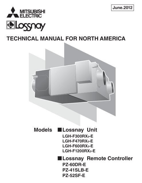
TECHNICAL MANUAL FOR NORTH AMERICA - MyLinkDrive
TECHNICAL MANUAL FOR NORTH AMERICA - MyLinkDrive
TECHNICAL MANUAL FOR NORTH AMERICA - MyLinkDrive

You also want an ePaper? Increase the reach of your titles
YUMPU automatically turns print PDFs into web optimized ePapers that Google loves.
June.2012<br />
<strong>TECHNICAL</strong> <strong>MANUAL</strong> <strong>FOR</strong> <strong>NORTH</strong> <strong>AMERICA</strong><br />
Models Lossnay Unit<br />
LGH-F300RX5-E<br />
LGH-F470RX5-E<br />
LGH-F600RX5-E<br />
LGH-F1200RX5-E<br />
Lossnay Remote Controller<br />
PZ-60DR-E<br />
PZ-41SLB-E<br />
PZ-52SF-E
Y11-001 Jun.2012
CHAPTER 1 Ventilation for Healthy Living<br />
i<br />
CONTENTS<br />
Lossnay Unit<br />
1. Necessity of Ventilation .................................................................................................................................... U-2<br />
2. Ventilation Standards ....................................................................................................................................... U-3<br />
3. Ventilation Method ............................................................................................................................................ U-4<br />
4. Ventilation Performance .................................................................................................................................... U-7<br />
5. Ventilation Load ................................................................................................................................................. U-9<br />
CHAPTER 2 Lossnay Construction and Technology<br />
1. Construction and Features .............................................................................................................................. U-16<br />
2. Lossnay Core Construction and Technology ..................................................................................................... U-16<br />
3. Total Energy Recovery Efficiency Calculation .................................................................................................. U-18<br />
4. What is a Psychrometric Chart? ........................................................................................................................ U-19<br />
5. Lossnay Energy Recovery Calculation .............................................................................................................. U-20<br />
CHAPTER 3 General Technical Considerations<br />
1. Lossnay Energy Recovery Effect ...................................................................................................................... U-22<br />
2. Calculating Lossnay Cost Savings .................................................................................................................... U-24<br />
3. Psychrometric Chart ......................................................................................................................................... U-26<br />
4. Determining Lossnay Core Resistance to Bacterial Cross-Contamination and Molds ..................................... U-28<br />
5. Lossnay Core Fire : retardant property ............................................................................................................. U-30<br />
6. Lossnay Core Sound Reducing Properties Test ............................................................................................... U-31<br />
7. Changes in the Lossnay Core .......................................................................................................................... U-32<br />
8. Comparing Energy Recovery Techniques ........................................................................................................ U-34<br />
CHAPTER 4 Characteristics<br />
1. How to Read the Characteristic Curves ........................................................................................................... U-38<br />
2. Calculating Static Pressure Loss ....................................................................................................................... U-38<br />
3. How to Obtain Efficiency from Characteristic Curves ....................................................................................... U-41<br />
4. Sound ............................................................................................................................................................... U-42<br />
5. NC Curves ....................................................................................................................................................... U-48<br />
CHAPTER 5 System Design Recommendations<br />
1. Lossnay Operating Environment ...................................................................................................................... U-52<br />
2. Sound Levels of Lossnay units with Built-in Fans ............................................................................................ U-53<br />
3. Attaching Air Filters .......................................................................................................................................... U-53<br />
4. Constructing the Ductwork ............................................................................................................................... U-53<br />
5. Bypass Ventilation ............................................................................................................................................ U-53<br />
6. Night purge function ......................................................................................................................................... U-53<br />
7. Transmission Rate of Various Gases and Maximum Workplace Concentration Levels .................................... U-53<br />
8. Solubility of Odors and Toxic Gases, etc., in Water and the Effect on the Lossnay Core ................................. U-54<br />
9. Automatic Ventilation Switching ......................................................................................................................... U-55<br />
10. Alternate Installation for Lossnay ..................................................................................................................... U-56<br />
11. Installing Supplementary Fan Devices ............................................................................................................. U-57
CHAPTER 6 Examples of Lossnay Applications<br />
1. Large Office Building ........................................................................................................................................ U-60<br />
2. Small-Scale Urban Building ............................................................................................................................. U-64<br />
3. Hospitals .......................................................................................................................................................... U-65<br />
4. Schools ............................................................................................................................................................ U-67<br />
5. Convention Halls, Wedding Halls in Hotels ....................................................................................................... U-68<br />
6. Public Halls (Facilities such as Day-care Centers) ............................................................................................. U-69<br />
CHAPTER 7 Installation Considerations<br />
1. LGH-Series Lossnay Ceiling Embedded-Type (LGH-RX5 Series) .................................................................... U-72<br />
CHAPTER 8 Filters<br />
1. Importance of Filters ........................................................................................................................................ U-76<br />
2. Dust .................................................................................................................................................................. U-76<br />
3. Calculation Table for Dust Collection Efficiency for Each Lossnay Filter ........................................................... U-77<br />
4. Comparing Dust Collection Efficiency Measurement Methods ........................................................................ U-78<br />
5. Calculating Dust Concentration Levels ............................................................................................................ U-80<br />
CHAPTER 9 Service Life and Maintenance<br />
1. Service Life ....................................................................................................................................................... U-82<br />
2. Cleaning the Lossnay Core and Pre-filter ......................................................................................................... U-82<br />
CHAPTER 10 Ventilation Standards in Each Country<br />
1. Ventilation Standards in Each Country .............................................................................................................. U-86<br />
2. United States of America ................................................................................................................................... U-87<br />
3 . United Kingdom ................................................................................................................................................ U-87<br />
CHAPTER 11 Lossnay Q and A ....................................................................................................................... U-90<br />
Note: The word “LGH-F300 to 1200RX5-E” in this Lossnay Technical Manual expresses both the products for 50Hz area and<br />
60Hz area, except for some parts where model name difference are written clearly.<br />
ii
iii<br />
Lossnay Remote Controller<br />
1. Summary ..................................................................................................................................................................... C-3<br />
2. Applicable Models ............................................................................................................................................... C-3<br />
3. Terminology ............................................................................................................................................................. C-4<br />
4. System Features and Examples<br />
4.1 Features ......................................................................................................................................................... C-5<br />
4.2 System Examples ........................................................................................................................................... C-6<br />
4.3 System Selection ............................................................................................................................................ C-8<br />
4.4 Basic System .................................................................................................................................................. C-11<br />
4.5 Interlocking with M-Series or P-Series ........................................................................................................... C-13<br />
4.6 Combining with City Multi ............................................................................................................................... C-14<br />
5. Examples of Applications Using Various Input and Output Terminals<br />
5.1 External Control Operating Mode Selection ................................................................................................... C-23<br />
5.2 Delayed Interlocked Operation ........................................................................................................................ C-24<br />
5.3 Multiple External Device Operation (PZ-60DR-E, PZ-41SLB-E, M-NET) ....................................................... C-24<br />
5.4 Multiple Lossnay Units Interlocked with One Indoor Unit (M-NET only) ......................................................... C-25<br />
5.5 Operation monitor output ................................................................................................................................ C-26<br />
5.6 Malfunction monitor output ............................................................................................................................. C-26<br />
5.7 By-pass operation monitor output ................................................................................................................... C-26<br />
5.8 Connection Method ........................................................................................................................................ C-26<br />
5.9 When switching High/Low/Extra-Low fan speed externally (when CO2 sensor or other equipment is connected) ..... C-28<br />
5.10 When switching By-pass externally ................................................................................................................ C-29<br />
5.11 When using the remote/local switching and the ON/OFF input (level signal) ................................................. C-29<br />
5.12 When connecting to the City Multi, Lossnay remote controller (PZ-52SF-E) or Mitsubishi Electric Air-Conditioner Network System (MELANS) .... C-30<br />
6. Precautions When Designing M-NET Systems<br />
6.1 M-NET Transmission Cable Power Supply ..................................................................................................... C-31<br />
6.2 Restrictions When the Lossnay Units are Connected to the Central Controller M-NET Transmission Cable .......... C-31<br />
6.3 Wiring Example .............................................................................................................................................. C-32<br />
6.4 Power Supply to the Indoor Unit Transmission Cable ..................................................................................... C-33<br />
7. M-NET Cable Installation<br />
7.1 Precautions When Installing Wiring ................................................................................................................ C-34<br />
7.2 Electrical Wiring .............................................................................................................................................. C-35<br />
7.3 Control Cable Length ....................................................................................................................................... C-36<br />
8. M-NET System Designs<br />
8.1 Address Definitions ........................................................................................................................................ C-37<br />
8.2 Precautions When Setting the Groups (when not interlocked with City Multi indoor units) ............................. C-39<br />
8.3 Precautions When Performing Interlock Settings (when interlocked with City Multi indoor units) ................... C-39
9. Automatic Ventilation Switching<br />
9.1 Effect of Automatic Ventilation Mode .............................................................................................................. C-40<br />
9.2 Ventilation mode control .................................................................................................................................. C-40<br />
10. Troubleshooting<br />
10.1 Service Flow ................................................................................................................................................... C-44<br />
10.2 Checklist ......................................................................................................................................................... C-45<br />
11. Installation method<br />
11.1 Electrical installation ....................................................................................................................................... C-64<br />
11.2 Connecting the power supply cable ................................................................................................................ C-66<br />
11.3 System configuration ...................................................................................................................................... C-66<br />
11.4 Function Setting .............................................................................................................................................. C-72<br />
11.5 Trial operation ................................................................................................................................................. C-76<br />
12. Lossnay Remote Controller (PZ-60DR-E)<br />
12.1 Parts Names ................................................................................................................................................... C-78<br />
12.2 Setting the Day of the Week and Time ........................................................................................................... C-79<br />
12.3 Using the Remote Controller .......................................................................................................................... C-79<br />
12.4 Care and Maintenance ................................................................................................................................... C-83<br />
12.5 Servicing ........................................................................................................................................................ C-83<br />
12.6 How to Install .................................................................................................................................................. C-84<br />
12.7 Test Run ......................................................................................................................................................... C-85<br />
12.8 Function Selection .......................................................................................................................................... C-86<br />
13. Lossnay Remote Controller (PZ-41SLB-E) .......................................................................................... C-91<br />
14. Lossnay M-NET Remote Controller (PZ-52SF-E) ............................................................................. C-92<br />
15. Appendix<br />
15.1 Centralized Controller (AG-150A) ................................................................................................................... C-93<br />
15.2 Remote Controllers for M-Series or P-Series indoor units ............................................................................ C-100<br />
15.3 ME Remote Controller (PAR-F27MEA) ........................................................................................................ C-103<br />
iV
Lossnay Unit
CHAPTER 1<br />
Ventilation for Healthy Living
CHAPTER 1 Ventilation for Healthy Living<br />
•<br />
Ventilation air must be introduced constantly at a set ratio in an air-conditioning system. The ventilation air introduced is to be<br />
mixed with the return air to adjust the temperature and humidity, supply oxygen, reduce odors, remove tobacco smoke, and to<br />
increase the air cleanliness.<br />
The standard ventilation (outdoor air intake) volume is determined according to the type of application, estimated number of<br />
occupants in the room, room area, and relevant regulations. Systems that accurately facilitate these requirements are required<br />
in buildings.<br />
1. Necessity of Ventilation<br />
The purpose of ventilation is basically divided into “oxygen supply”, “air cleanliness”, “temperature control” and “humidity control”.<br />
Air cleanliness includes eliminating “odors”, “gases”, “dust” and “bacteria”. Ventilation needs are divided into “personal comfort”,<br />
“optimum environment for animals and plants”, and “optimum environment for machinery and constructed materials”.<br />
Ventilation regulations are detailed in a variety of codes and standards applied to mechanical systems in buildings. Energy<br />
efficiency codes also often apply to the design of ventilation systems.<br />
1.1 Room Air Environment in Buildings<br />
In Japan, the “Building Management Law”, a law concerning the sanitary environment in buildings, designates 11 applications<br />
including offices, shops, and schools with a total floor area of 32,300ft 2 (3,000m 2 ) or more, as buildings. Law maintenance<br />
and ventilation, water supply, discharge management according to the Environmental Sanitation Management Standards is<br />
obligatory.<br />
The following table gives a specific account of buildings in Tokyo.<br />
(Tokyo Food and Environment Guidance Center Report)<br />
Specific Account of Buildings in Tokyo (March, 2003)<br />
Note: Excludes buildings with an expanded floor space of 32,300 to 58,820ft 2 (3,000 to 5,000m 2 ) in particular areas.<br />
Results of the air quality measurement public<br />
inspection and the standard values that were<br />
not met (percentage of unsuitability) for the<br />
approximately 500 buildings examined in 1980<br />
are shown in the chart at the right.<br />
There was a large decrease in high percentages<br />
of floating particles, but there was almost no<br />
change in temperature and carbon dioxide. The<br />
highest percentage of unsuitability in 2006 is<br />
relative humidity with 36%, followed by carbon<br />
dioxide at 28%.<br />
U-2<br />
Number of Buildings %<br />
Offices 1,467 56.7<br />
Shops 309 22.0<br />
Department Stores 63 2.4<br />
Schools 418 16.2<br />
Inns 123 4.8<br />
Theaters 86 3.3<br />
Libraries 12 0.5<br />
Museums 11 0.4<br />
Assembly Halls 63 2.4<br />
Art Museums 8 0.3<br />
Amusement Centers 27 1.0<br />
Total 2,587 100.0<br />
Percentage of unsuitable air quality (%)<br />
60 relative humidity<br />
50<br />
40<br />
30<br />
20<br />
10<br />
Percentage Unsuitable Air Quality by Year<br />
carbon dioxide<br />
temperature<br />
carbon monoxide<br />
ventilation<br />
floating particles<br />
(tobacco smoke)<br />
0<br />
71 73 75 76 77 78 79 80 81 82 83 84 85 86 87 88 89 90 91 92 93 94 95 96 97 98 9900 01 02 03 0405 06<br />
(From reference data in the 2006 edition of the “Water Supply (year)<br />
Division, Dept. of Localized Public Health, Tokyo Metropolitan<br />
Government, Bureau of Public Health”)
CHAPTER 1 Ventilation for Healthy Living<br />
•<br />
In Japan, an Instruction Guideline based on these regulations has been issued, and unified guidance is followed. Part of the<br />
Instruction Guideline regarding ventilation is shown below.<br />
• The ventilation air intake must be 33ft (10m) or higher from ground level, and be located at an appropriate distance from the<br />
exhaust air outlet. (Neighbouring buildings must also be considered.)<br />
• The ventilation air intake volume must be 15 to 18 CFM·occupant. (25 to 30 m3 /h·occupant.)<br />
•<br />
•<br />
An air volume measurement access hole must be installed at an appropriate position to measure the treated air volume of<br />
the ventilating device.<br />
Select the position and shape of the supply diffuser and return grille to evenly distribute the ventilation air in the room.<br />
1.2 Effect of Air Contamination<br />
Effect of Oxygen (O2) Concentration<br />
Concentration (%) Standards and Effect of Concentration Changes<br />
Approx. 21 Standard atmosphere.<br />
20.5<br />
20 - 19<br />
Ventilation air volume standard is a guideline where concentration does not decrease more than 0.5%<br />
from normal value. (The Building Standard Law of Japan)<br />
Oxygen deficiency of this amount does not directly endanger life in a normal air pressure, but if there is a<br />
combustion device in the area, the generation of CO will increase rapidly due to incomplete combustion.<br />
18 Industrial Safety and Health Act. (Hypoxia prevention regulations.)<br />
16 Normal concentration in exhaled air.<br />
16 - 12 Increase in pulse and breathing; resulting in dizziness and headaches.<br />
15 Flame in combustion devices will extinguish.<br />
12 Short term threat to life.<br />
7 Fatal<br />
Effect of Carbon Monoxide (CO) 10,000 ppm = 1%<br />
Concentration (ppm) Effect of Concentration Changes<br />
0.01 - 0.2 Standard atmosphere.<br />
5 Tolerable long-term value.<br />
10<br />
20<br />
50<br />
100<br />
The Building Standard Law of Japan, Law for Maintenance of Sanitation in Buildings.<br />
Environmental standard for a 24-hour average.<br />
Considered to be the tolerable short-term value.<br />
Environmental standard for an 8-hour average.<br />
Tolerable concentration for working environment.<br />
(Japan Industrial Sanitation Association)<br />
No effect for 3 hours. Effect noticed after 6 hours.<br />
Headache, illness after 9 hours; harmful for long-term but not fatal.<br />
200 Light headache in the frontal lobe in 2 to 3 hours.<br />
400 Headache in the temporal lobe, nausea in 1 to 2 hours; headache in the back of head in 2.5 to 3 hours.<br />
800 Headache, dizziness, nausea, convulsions in 45 minutes. Comatose in 2 hours.<br />
1,600 Headache, dizziness in 20 minutes. Death in 2 hours.<br />
3,200 Headache, dizziness in 5 to 10 minutes. Death in 30 minutes.<br />
6,400 Death in 10 to 15 minutes.<br />
12,800 Death in 1 to 3 minutes.<br />
Several 10,000 ppm<br />
(Several %)<br />
Level may be found in automobile exhaust.<br />
Approx. 5 ppm is<br />
the annual<br />
average value in<br />
city<br />
environments.<br />
This value may<br />
exceed 100 ppm<br />
near roads, in<br />
tunnels and<br />
parking areas.<br />
U-3
CHAPTER 1 Ventilation for Healthy Living<br />
•<br />
Effect of Carbon Dioxide (CO2)<br />
Note: According to Facility Check List published by Kagekuni-sha.<br />
1.3 Effect of Air Contamination in Buildings<br />
•<br />
Dirtiness of interior<br />
New ceilings, walls and ornaments will turn yellow from dust in 1 to 2 years.<br />
2. Ventilation Standards<br />
The legal standards for ventilation differ according to each country. Please follow the standards set by your country. In the U.S.,<br />
ASHRAE revised their standards in 1989 to become more strict.<br />
U-4<br />
Concentration (%) Effect of Concentration Changes<br />
0.03 (0.04) Standard atmosphere.<br />
0.04 - 0.06 City air.<br />
0.07 Tolerable concentration when many occupants stay in the space for long time. There is no toxic level in<br />
0.10<br />
General tolerable concentration.<br />
The “Building Standard Law” of Japan, “Law for Maintenance of Sanitation in Buildings”.<br />
0.15 Tolerable concentration used for ventilation calculations.<br />
0.2 - 0.5 Relatively poor.<br />
0.5 or more Very poor.<br />
0.5 Long-term safety limits (U.S. Labor Sanitation) ACGIH, regulation of working offices.<br />
2 Depth of breathing and inhalation volume increases 30%.<br />
3 Work and physical functions deteriorate, increase breathing doubles.<br />
4 Normal exhalation concentration.<br />
4 - 5<br />
8<br />
18 or more Fatal<br />
CO2 alone.<br />
However, these<br />
tolerable concentrations<br />
are a guideline of the<br />
contamination estimated<br />
when the physical and<br />
chemical properties of<br />
the air deteriorate in<br />
proportion to the<br />
increase of CO2.<br />
The respiratory center is stimulated; depth and times of breathing increases. Dangerous if inhaled for a<br />
long period. If an O2 deficiency also occurs, conditions will rapidly deteriorate and become dangerous.<br />
When inhaled for 10 minutes, breathing difficulties, redness in the face and headaches will occur.<br />
Conditions will worsen when there is also an O2 deficiency .
3. Ventilation Method<br />
3.1 Comparing of Ventilation Methods<br />
There are two main types of ventilation methods.<br />
CHAPTER 1 Ventilation for Healthy Living<br />
•<br />
Centralized Ventilation Method<br />
Mainly used in large buildings, with the ventilation air intake being installed in one machine room. For this method, primary<br />
treatment of the ventilation air, such as energy recovery to the intake air and dust removal, is performed via distribution to the<br />
building by ducts.<br />
Independent Zoned Ventilation Method<br />
Mainly used in small to medium sized buildings, with areas being ventilated using ventilation air intake via independent<br />
ventilation devices. The use of this method has recently increased as independent control is becoming more feasible.<br />
Centralized Ventilation Method Independent Zoned Ventilation Method<br />
Air intake<br />
(ventilation<br />
air) Filters<br />
Lossnay<br />
Each unit<br />
Exhaust<br />
Air exhaust<br />
(stale air)<br />
Supply fan<br />
1) System operation with cassette-type indoor units of air conditioner<br />
Cassette-type indoor units of<br />
air conditioner or fan coil unit<br />
2) System operation with ceiling embedded-type indoor units of air conditioner<br />
Ceiling embedded-type indoor units<br />
of air conditioner or fan coil unit<br />
3) Independent operation with ceiling suspended-type indoor units of air conditioner<br />
Cassette-type or ceiling<br />
suspended-type indoor units of<br />
air conditioner or fan coil unit<br />
Supply grill<br />
Exhaust grill<br />
Exhaust grill<br />
Ceiling recessedtype<br />
Lossnay<br />
Finished ceiling<br />
Finished ceiling<br />
Exhaust air<br />
Ventilation air<br />
Ceiling recessedtype<br />
Lossnay<br />
Finished ceiling<br />
Exhaust grill<br />
Exhaust air<br />
Ventilation air<br />
Ceiling recessedtype<br />
Lossnay<br />
Exhaust air<br />
Ventilation air<br />
U-5
CHAPTER 1 Ventilation for Healthy Living<br />
•<br />
Comparing Centralized Ventilation and Independent Zoned Ventilation Methods<br />
System Flexibility<br />
U-6<br />
Control<br />
Comfort<br />
System Management<br />
Fan Power<br />
Installation Area<br />
Centralized Ventilation Method Independent Zoned Ventilation Method<br />
The air transfer distance is long, thus requiring<br />
much fan power.<br />
• Independent equipment room is required.<br />
• Duct space is required.<br />
• Penetration of floors with vertical shaft is not<br />
recommended in terms of fire prevention.<br />
As the air transfer distance is short, the fan power is<br />
small.<br />
• Independent equipment room is not required.<br />
• Piping space is required only above the ceiling.<br />
Zoning Generalized per system. Can be used for any one area.<br />
Design<br />
Maintenance and<br />
Management<br />
Trouble influence<br />
Costs<br />
• Design of outer wall is not lost.<br />
• The indoor supply air diffuser and return grille can<br />
be selected without restrictions for an appropriate<br />
design.<br />
• As the usage set time and ventilation volume<br />
control, etc., are performed in a central monitoring<br />
room, the user’s needs may not be met<br />
appropriately.<br />
• A large amount of ventilation is required even for<br />
a few occupants.<br />
• An ideal supply air diffuser and return grille<br />
position can be selected as the supply air diffuser<br />
and return grille can be positioned without<br />
restrictions.<br />
• The only noise in the room is the sound of air movement.<br />
• Antivibration measures must be taken as the fan in<br />
the equipment room is large.<br />
• Centralized management is easy as it can be<br />
performed in the equipment room.<br />
• The equipment can be inspected at any time.<br />
• The entire system is affected.<br />
• Immediate inspection can be performed in the<br />
equipment room.<br />
Because there are many common-use areas, if the<br />
building is a tenant building, an accurate<br />
assessment of operating cost is difficult.<br />
• The number of intakes and exhaust air outlets on<br />
an outside wall will increase; design must be<br />
considered.<br />
• The design will be fixed due to installation fittings,<br />
so the design of the intakes and exhaust air<br />
outlets must be considered.<br />
• The user in each zone can operate the ventilator<br />
without restrictions.<br />
• The ventilator can be operated even during offpeak<br />
hours.<br />
• Consideration must be made because of the<br />
noise from the main unit.<br />
• Antivibration measures are often not required as<br />
the unit is compact and any generated vibration<br />
can be dispersed.<br />
• Work efficiency is poor because the equipment is<br />
not centrally located.<br />
• An individual unit can be inspected only when the<br />
room it serves is vacant.<br />
• Limited as only independent units are affected.<br />
• Consultation with the tenant is required prior to<br />
inspection of an individual unit.<br />
Invoicing for each zone separately is possible, even<br />
in a tenant building.
4. Ventilation Performance<br />
CHAPTER 1 Ventilation for Healthy Living<br />
•<br />
The ventilation performance is largely affected by the installation conditions. Optimum performance may not be achieved<br />
unless the model and usage methods are selected according to the conditions.<br />
Generally, the ventilation performance is expressed by “air volume” and “wind pressure (static pressure)”.<br />
4.1 Air Volume<br />
Air volume equals the volume of air exhausted (or supplied) by the unit in a given period, and is expressed in CFM or m 3 /hr (hour).<br />
4.2 Wind Pressure<br />
When a piece of paper is placed in front of a fan then released, the piece of paper will be blown away. The force that blows the<br />
paper away is called wind pressure and is normally expressed in inH2O. Wind pressure is divided into the following three types:<br />
4.2.1 Static Pressure<br />
The force that effects the surroundings when the air is contained such as in an automobile tyre or rubber balloon. For example,<br />
in a water gun, the hydraulic pressure increases when pressed by a piston. If there is a small hole, the water is forced out of<br />
that opening. The pressure of the water is equivalent to air static pressure. The higher the pressure, the farther the water (air)<br />
can be forced out.<br />
4.2.2 Dynamic Pressure<br />
The speed at which air flows; for example, the force at which a hurricane presses against a building.<br />
4.2.3 Total Pressure<br />
The total force that wind has, and is the sum of the static pressure and dynamic pressure.<br />
U-7
CHAPTER 1 Ventilation for Healthy Living<br />
•<br />
4.3 Measuring the Air Volume and Static Pressure<br />
Mitsubishi Electric measures the Lossnay’s air volume and static pressure with a device as shown below according to Japan<br />
Industrial Standards (JIS B 8628).<br />
Measuring Device Using Orifice (JIS B 8628 Standards)<br />
Measurement Method<br />
The unit is operated with the throttle device fully closed. There is no air flow at this time, and the air volume is 0. The maximum<br />
point of the static pressure (Point A, the static pressure at this point is called the totally closed pressure) can be obtained. Next,<br />
the throttle device is gradually opened, the auxiliary fan is operated, and the median points (Points B, C and D) are obtained.<br />
Finally, the throttle device is completely opened, and the auxiliary fan is operated until the static pressure in the chamber reaches 0.<br />
The maximum point of the air volume (Point E, the air volume at this point is called the fully opened air volume) is obtained. The<br />
points are connected as shown below, and are expressed as air volume, static pressure curves (Q-H curve).<br />
U-8<br />
Test unit<br />
Blower<br />
Connection<br />
Supply<br />
Air<br />
(SA)<br />
Smoothing<br />
grid<br />
Static pressure (H)<br />
Chamber<br />
Smoothing<br />
net<br />
Static pressure in chamber<br />
(Static pressure measurement)<br />
Wind gauge<br />
duct path Orifice<br />
Air volume (Q)<br />
Wind dispersing place<br />
Wind gauge<br />
duct path<br />
Pressure<br />
difference before<br />
and after orifice<br />
(Air volume<br />
measurement)<br />
Smoothing<br />
net<br />
Return<br />
Air<br />
(RA)<br />
Orifice<br />
A) When measuring the supply air volume (with the orifice plate)<br />
B) When measuring the return air volume (with the orifice plate)<br />
Smoothing<br />
grid<br />
Blower<br />
Connection<br />
Damper<br />
Test unit<br />
Static pressure in chamber<br />
(Static pressure measurement)
5. Outdoor Air (ventilation) Load<br />
5.1 How to Calculate Each Approximate Load<br />
5.1 A (US unit)<br />
CHAPTER 1 Ventilation for Healthy Living<br />
•<br />
The ventilation air load can be calculated with the following formula if the required ventilation intake volume “Q CFM” is known:<br />
(Ventilation air load) = γ · QF · (iO - iR)<br />
= γ [lb/ft 3 ] × S[ft 2 ] × k × n [occupant/ft 2 ] × Vf [CFM / occupant] × (iO - iR): ∆i [Btu/lb]<br />
γ : Specific air gravity - 0.0749 lb/ft 3<br />
S : Building’s airconditioned area<br />
k : Thermal coefficient; generally 0.7 - 0.8.<br />
n : The average population concentration is the inverse of the occupancy area per person. If the number of persons in the<br />
room is unclear, refer to the Floor space per person table below.<br />
Vf : Ventilation air intake volume per occupant<br />
Refer to the Required ventilation air intake volume per occupant table below.<br />
iO : Ventilation air enthalpy - Btu/lb<br />
iR : Indoor enthalpy - Btu/lb<br />
Floor Space per Occupant (ft 2 )<br />
(According to the Japan Federation of Architects and Building Engineers Associations)<br />
Office Building<br />
Department Store, Shop<br />
Average Crowded Empty<br />
Required Ventilation Air Intake Volume Per Occupant (CFM per occupant)<br />
Restaurant<br />
Theater or<br />
Cinema Hall<br />
General Design 43 - 75 5.4 - 21.5 5.4 - 21.5 54 - 86 10.8 - 21.5 4.3 - 6.5<br />
Value 54 32.3 10.8 64.6 16.1 5.4<br />
Amount of Cigarette Smoking<br />
Extremely Heavy<br />
Quite Heavy<br />
Heavy<br />
Light<br />
None<br />
Application Example<br />
Broker’s office<br />
Newspaper editing room<br />
Conference room<br />
Bar<br />
Cabaret<br />
Office<br />
Restaurant<br />
Shop<br />
Department store<br />
Theater<br />
Hospital room<br />
Required Ventilation Volume<br />
Recommended Value Minimum Value<br />
50 30<br />
30 25<br />
Caution<br />
The amount of smoking that could be present in each type of room must be carefully considered when obtaining the<br />
required ventilation volume shown in the table above.<br />
15<br />
10<br />
12<br />
15 10<br />
15<br />
20<br />
10<br />
15<br />
U-9
CHAPTER 1 Ventilation for Healthy Living<br />
•<br />
5.1 B (SI unit)<br />
The ventilation air load can be calculated with the following formula if the required ventilation intake volume “Q m 3 /h” is known:<br />
(Ventilation air load) = γ · QF · (iO - iR)<br />
= γ [kg/m 3 ] × S [m 2 ] × k × n [occupant/m 2 ] × Vf [m 3 /h·occupants] × (iO - iR): ∆i [kJ/kg]<br />
γ : Specific air gravity - 1.2 kg/m 3<br />
S : Building’s air-conditioned area<br />
k : Thermal coefficient; generally 0.7 - 0.8.<br />
n : The average population concentration is the inverse of the occupancy area per occupant. If the number of occupants in the<br />
room is unclear, refer to the Floor space per occupant table below.<br />
Vf : Ventilation air intake volume per occupant<br />
Refer to the Required ventilation air intake volume per occupant table below.<br />
iO : Ventilation air enthalpy - kJ/kg<br />
iR : Indoor enthalpy - kJ/kg<br />
Floor Space per Occupant (m 2 )<br />
(According to the Japan Federation of Architects and Building Engineers Associations)<br />
Required Ventilation Air Intake Volume Per Occupant (m 3 /h·occupant)<br />
U-10<br />
Office Building<br />
Department Store, Shop<br />
Average Crowded Empty<br />
Restaurant<br />
Theater or<br />
Cinema Hall<br />
General Design 4 - 7 0.5 - 2 0.5 - 2 5 - 8 1 - 2 0.4 - 0.6<br />
Value 5 3.0 1.0 6.0 1.5 0.5<br />
Amount of Cigarette Smoking<br />
Extremely Heavy<br />
Quite Heavy<br />
Heavy<br />
Light<br />
None<br />
Application Example<br />
Broker’s office<br />
Newspaper editing room<br />
Conference room<br />
Bar<br />
Cabaret<br />
Office<br />
Restaurant<br />
Shop<br />
Department store<br />
Theater<br />
Hospital room<br />
Required Ventilation Volume<br />
Recommended Value Minimum Value<br />
85 51<br />
51 42.5<br />
Caution<br />
The amount of smoking that could be present in each type of room must be carefully considered when obtaining the<br />
required ventilation volume shown in the table above.<br />
25.5<br />
17<br />
20<br />
25.5 17<br />
25.5<br />
34<br />
17<br />
25.5
CHAPTER 1 Ventilation for Healthy Living<br />
•<br />
See below for Calculation examples of determining ventilation load during both cooling and heating.<br />
5.2 Ventilation Load During Cooling (In an Office Building)<br />
•<br />
Cooling Load Per Unit Area<br />
When the volume of ventilation air per occupants is 15 CFM (25 m 3 /h), and the number of occupants per 1 ft 2 is 0.0186 (1 m 2 is<br />
0.2), the cooling load will be approximately 14.6 W/ft 2 (157.0 W/m 2 ).<br />
•<br />
Cooling Load Classifications<br />
(a) Indoor penetration heat<br />
(b) Indoor generated heat<br />
(a) Is the heat penetrating the room, and often is 30 to 40% of the entire cooling load?<br />
(b) Is the heat generated in the room?<br />
(c) Is applies only when reheating is necessary?<br />
(d) Is the heat generated when ventilation air is mixed into part of the supply air diffuser volume and introduced into the room?<br />
The ventilation air is introduced to provide ventilation for the room occupants, and is referred to as the ventilating load.<br />
Typical Load Values During Cooling<br />
Ventilation air<br />
load 33.8%<br />
4.9 W/ft 2<br />
(53.0 W/m 2 )<br />
Indoor<br />
penetration<br />
heat 30.3%<br />
4.4 W/ft 2<br />
(47.6 W/m 2 )<br />
Indoor<br />
generated heat<br />
(occupants, lighting<br />
equipment) 35.9%<br />
5.2 W/ft 2 (56.4 W/m 2 )<br />
Ventilation Load<br />
Standard design air conditions in Tokyo<br />
Office Building Department Store, Shop<br />
14.6 W/ft 2<br />
(157.0 W/m 2 )<br />
Heat generated from walls (qWS)<br />
Heat generated from glass<br />
Accumulated heat load in walls (qSS)<br />
Generated heat from occupants<br />
Generated heat from electrical equipment<br />
from direct sunlight (qGS)<br />
from conduction and convection (qGS)<br />
Sensible heat (qHS)<br />
Latent heat (qHL)<br />
(c) Reheating load (qRL)<br />
(d) Outdoor air load<br />
Cooling<br />
Sensible heat (qFS)<br />
Latent heat (qFL)<br />
Sensible heat (qES)<br />
Latent heat (qEL)<br />
Load Type Load<br />
Ventilation Air Load 4.9 W/ft 2 (53.0 W/m 2 )<br />
Indoor<br />
Generated Heat<br />
Occupants 2.5 W/ft 2 (26.4 W/m 2 )<br />
Lighting Equipment 2.8 W/ft 2 (30.0 W/m 2 )<br />
Indoor Penetration Heat 4.4 W/ft 2 (47.6 W/m 2 )<br />
Total 14.6 W/ft 2 (157.0 W/m 2 )<br />
Conditions: Middle south-facing floor of a typical office building.<br />
Dry Bulb Temp. Relative Humidity Wet Bulb Temp. Enthalpy Enthalpy Difference<br />
Outdoor Air 91.4°F (33 °C) 63% 80.6°F (27 °C) 36.5 Btu/Ib (85 kJ/kg)<br />
Indoor Air 78.8°F (26 °C) 50% 65.7°F (18.7 °C) 22.9 Btu/Ib (53.2 kJ/kg)<br />
13.6 Btu/Ib (31.8 kJ/kg)<br />
<br />
When the load per floor area of 1 ft 2 with a ventilation volume of 15 CFM·occupant is calculated with the air conditions detailed<br />
above, the following is obtained:<br />
Ventilation air load = 0.0749 Ib/ft 3 (Specific gravity of air) × 0.0186 occupant/ft 2 (number of occupants per 1 ft 2 )<br />
× 15 CFM·occupants (ventilation air volume) × 13.7 Btu/Ib (air enthalpy difference indoor/outdoor) = 0.286 Btu/min·ft 2 (4.9 W/ft 2 )<br />
<br />
When the load per floor area of 1 m 2 with a ventilation volume of 25 m 3 /h·occupant is calculated with the air conditions detailed<br />
above, the following is obtained:<br />
Ventilation air load = 1.2 kg/m 3 (Specific gravity of air) × 0.2 occupant/m 2 (number of occupants per 1 m 2 )<br />
× 25 m 3 /h·occupants (ventilation air volume) × 31.8 kJ/kg (air enthalpy difference indoor/outdoor) = 190.8 kJ/h·m 2 (53.0 W/m 2 )<br />
The Lossnay recuperates approximately 70% of the exhaust air load and saves on approximately 20% of the total load.<br />
U-11
CHAPTER 1 Ventilation for Healthy Living<br />
•<br />
•<br />
Determining Internal Heat Gain<br />
When classifying loads, the internal heat gain (indoor generated heat + indoor penetration heat) is the ventilation air load<br />
subtracted from the approximate cooling load when it is assumed that there is no reheating load.<br />
•<br />
•<br />
(Internal heat gain)<br />
= 14.6 W/ft 2 (157.0 W/m 2 ) – 4.9 W/ft 2 (53.0 W/m 2 ) = 9.7 W/ft 2 (104.0 W/m 2 )<br />
The value of internal heat gain is based on assumptions for typical loads. To determine individual levels of internal heat gain,<br />
the following is suggested:<br />
Indoor Generated Heat<br />
(1) Heat generated from occupants<br />
Heat generation design value per person (occupant) in the office:<br />
U-12<br />
Sensible heat (SH) = 63.0 W/person (W·occupant)<br />
Latent heat (LH) = 69.0 W/person (W·occupant)<br />
Total heat (TH) = 132.0 W/person (W·occupant)<br />
The heat generated per 1 ft 2 (m 2 ) of floor space:<br />
Heat generated from occupants = 132.0 W/person (132.0 W·occupant) × 0.0186 person/ft 2 (0.2 occupant/m 2 ) = 2.5W/ft 2 (26.4 W/m 2 )<br />
(2) Heat generated from electrical equipment (lighting)<br />
The approximate value of the lighting and power required for a general office with lighting of 300 - 350 Lux, is 1.9 - 2.8 W/ft 2<br />
(20 - 30 W/m 2 ).<br />
•<br />
Heat generated from electrical equipment (lighting) = 30 W/m 2<br />
Indoor Penetration Heat<br />
The heat that penetrates into the building from outside, which can be determined by subtracting the amount of heat generated<br />
by occupants and lighting from the internal heat gain.<br />
(Indoor infiltration heat)<br />
= 9.7 - (2.5 + 2.8) = 4.4 W/ft 2 (104.0 – (26.4 + 30.0) = 47.6 W/m 2 )
5.3 Ventilation Load During Heating<br />
• Classification of Heating Load<br />
CHAPTER 1 Ventilation for Healthy Living<br />
•<br />
During heating, the heat generated by occupants and electrical equipment in the room can be subtracted from the heating load.<br />
If the warming-up time at the start of heating is short, however, the generated heat may be ignored in some cases.<br />
Percentage of Load<br />
•<br />
•<br />
•<br />
(a)<br />
(b)<br />
Ventilation<br />
air load 41.9%<br />
5.2 W/ft 2<br />
(56.0 W/m 2 )<br />
Indoor heat<br />
loss<br />
Heating Load Per Unit Area<br />
When the ventilation air volume per occupant is 15 CFM (25 m 3 /h), and the number of occupants per 1 ft 2 is 0.0186 (1 m 2<br />
is 0.2), the heating load will be approximately 12.4 W/ft 2 (133.7 W/m 2 ).<br />
Internal Heat Loss<br />
In terms of load classification, the internal heat loss is the value of the ventilation air load subtracted from the approximate<br />
heating load.<br />
Internal heat loss = 12.4 W/ft 2 – 5.2 W/ft 2 = 7.2 W/ft 2 (133.7 W/m 2 – 56.0 W/m 2 = 77.7 W/m 2 )<br />
Ventilation Load<br />
Standard design air conditions in Tokyo<br />
Heating<br />
Ventilation<br />
load<br />
Class Heat Load<br />
Indoor heat<br />
loss 58.1%<br />
7.2 W/ft 2<br />
(77.7 W/m 2 )<br />
Heat escaping from walls (qWS)<br />
Heat escaping from glass (qGS)<br />
Heat loss from conduction and convection (qGS)<br />
Accumulated heat load in walls (qSS)<br />
Sensible heat (qFS)<br />
Latent heat (qFL)<br />
12.4 W/ft 2<br />
(133.7 W/m 2 )<br />
Type of Load Load<br />
Ventilation Air Load 5.2 W/ft 2 (56.0 W/m 2 )<br />
Internal Heat 7.2 W/ft 2 (77.7 W/m 2 )<br />
Total 12.4 W/ft 2 (133.7 W/m 2 )<br />
Conditions: Middle south-facing floor of a typical office building.<br />
Dry Bulb Temp. Relative Humidity Wet Bulb Temp. Enthalpy Enthalpy Difference<br />
Outdoor Air 32 °F (0 °C) 50% 26.6 °F (–3 °C) 2.1 Btu/Ib (5.0 kJ/kg)<br />
Indoor Air 68 °F (20 °C) 50% 56.7 °F (13.7 °C) 16.6 Btu/Ib (38.5 kJ/kg)<br />
14.4 Btu/Ib (33.5 kJ/kg)<br />
<br />
When the load per 1 ft 2 of floor area with a ventilation volume of 15 CFM·occupant is calculated with the air conditions<br />
detailed above, the following is obtained:<br />
Ventilation air load = 0.749 Ib/ft 3 × 0.0186 occupants/ft 2 × 15 CFM·occupant × 14.4 Btu/Ib = 0.30 Btu/min·ft 2 (5.2 W/ft 2 )<br />
<br />
When the load per 1 m 2 of floor area with a ventilation volume of 25 m 3 /h·occupant is calculated with the air conditions<br />
detailed above, the following is obtained:<br />
Ventilation air load = 1.2 kg/m 3 × 0.2 occupants/m 2 × 25 m 3 /h·occupant × 33.5 kJ/kg = 201.0 kJ/h·m 2 (56 W/m 2 )<br />
The Lossnay recuperates approximately 70% of the ventilation load and saves on approximately 30% of the total load.<br />
U-13
CHAPTER 2<br />
Lossnay Construction and Technology
CHAPTER 2 Lossnay Construction and Technology<br />
•<br />
1. Construction and Features<br />
• Construction<br />
Lossnay is constructed so that the exhaust air passage from the<br />
indoor side to the outdoor side (RA → EA) and the ventilation air<br />
passage from the outdoor side to the indoor side (OA → SA) cross.<br />
The Lossnay Core is located at this crosspoint, and recovers the<br />
heat by conduction through the separating medium between these<br />
airflows. This enables the heat loss during exhaust to be greatly<br />
reduced.<br />
* RA : Return Air<br />
EA : Exhaust Air<br />
OA : Outdoor Air<br />
SA : Supply Air<br />
U-16<br />
Main Features<br />
Lossnay Core<br />
SA (Supply air diffuser)<br />
Supply fan<br />
RA (Return air)<br />
Exhaust side filter<br />
EA (Exhaust air)<br />
Exhaust fan<br />
OA (Outdoor air)<br />
Intake side filter<br />
Note: The duct inlet and outlet are linear in the<br />
actual product.<br />
(1) Cooling and heating maintenance fees are reduced while ventilating.<br />
(2) The system size of Heating/cooling system and cooling/heating load can be reduced.<br />
(3) Dehumidifying during summer and humidifying during winter is possible.<br />
(4) Comfortable ventilation is possible with the outdoor air can be adjusted to parallel the room temperature.<br />
(5) Sound can be reduced.<br />
2. Lossnay Core Construction and Technology<br />
•<br />
Simple Construction<br />
The Lossnay core is a cross-air passage total energy recovery unit<br />
constructed from specially treated membrane with a corrugated<br />
structure.<br />
The fresh air and exhaust air passages are totally separated<br />
allowing the fresh air to be introduced without mixing with the<br />
exhaust air.<br />
• Principle<br />
The Lossnay Core uses the heat transfer properties and moisture<br />
permeability of the treated membrane. Total heat (sensible heat<br />
plus latent heat) is transferred from the stale exhaust air to the<br />
ventilation air being introduced into the system when they pass<br />
through the Lossnay.<br />
SA<br />
Supply Air<br />
Indoors Outdoors<br />
(Fresh heating/cooling air)<br />
Partition<br />
plate<br />
(Treated<br />
membrane)<br />
EA<br />
Exhaust Air<br />
(Stale air)<br />
Spacer plate<br />
(Treated<br />
membrane)<br />
OA<br />
Outdoor air<br />
• Treated membrane<br />
The cellulose membrane partition plates are treated with special<br />
chemicals so that the Lossnay Core is an appropriate energy<br />
recovery unit for the ventilator.<br />
The membrane has many unique properties:<br />
(1) Incombustible and strong.<br />
RA<br />
Return Air<br />
(Dirty heating/cooling air)<br />
(Fresh air)<br />
(2) Has selective hydroscopicity and moisture permeability that permits the passage of only water vapor (including some<br />
water-soluble gases).<br />
(3) Has gas barrier properties that does not permit gases such as CO2 and other pollutants from entering the conditioned<br />
space.
•<br />
Total Energy Recovery Mechanism<br />
CHAPTER 2 Lossnay Construction and Technology<br />
•<br />
Sensible Heat and Latent Heat<br />
The heat that enters and leaves in accordance with rising or falling temperatures is called sensible heat. The direct movement of<br />
water vapor molecules or due to the changes in the matter’s physical properties (evaporation, condensation) is called latent heat.<br />
(1) Temperature (Sensible Heat) Recovery<br />
1) Heat conduction and heat passage is performed through a<br />
partition plate from the high temperature to low temperature<br />
side.<br />
2) As shown in the diagram at right, the energy recovery<br />
efficiency is affected by the resistance of the partition plate.<br />
For Lossnay, there is little difference when compared to<br />
materials such as copper or aluminium that also have high<br />
thermal conductivity.<br />
Heat Resistance Coefficients<br />
Lossnay Plate Cu Al<br />
Ra1 10 10 10<br />
Rp 1 0.00036 0.0006<br />
Ra2 10 10 10<br />
Total 21 20.00036 20.0006<br />
(2) Humidity (Latent Heat) Recovery<br />
• Water vapor travels through the partition plate from the high<br />
humidity to low humidity side via the differential pressure in<br />
the vapor.<br />
t1<br />
High humidity side<br />
Partition plate<br />
Ra1+Ra2»Rp<br />
Partition plate<br />
t2<br />
Ra1<br />
Ra2<br />
Rp<br />
Low humidity side<br />
U-17
CHAPTER 2 Lossnay Construction and Technology<br />
•<br />
3. Total Energy Recovery Efficiency Calculation<br />
The Lossnay Core’s energy recovery efficiency can be considered<br />
using the following three transfer rates:<br />
(1) Temperature (sensible heat) recovery efficiency<br />
(2) Humidity (latent heat) recovery efficiency<br />
(3) Enthalpy (total heat) recovery efficiency<br />
The energy recovery effect can be calculated if two of the above<br />
efficiencies are known.<br />
•<br />
•<br />
•<br />
Each energy efficiency can be calculated with the formulas in the<br />
table.<br />
When the supply and exhaust air volumes are equal, the energy<br />
recovery efficiencies on the supply and exhaust sides are the<br />
same.<br />
When the supply and exhaust air volumes are not equal, the total<br />
energy recovery efficiency is low if the exhaust volume is lower,<br />
and high if the exhaust volume is higher.<br />
Temperature recovery<br />
efficiency (%)<br />
Enthalpy recovery<br />
efficiency (%)<br />
U-18<br />
Item Formula<br />
ηt =<br />
ηi =<br />
tOA - tSA<br />
tOA - tRA<br />
iOA - iSA<br />
iOA - iRA<br />
×100<br />
× 100<br />
SA<br />
Fresh air exhaust<br />
Indoors Outdoors<br />
(Fresh heating/cooling air)<br />
RA<br />
Stale air induction<br />
(Dirty heating/cooling air)<br />
η : Efficiency (%)<br />
EA<br />
Exhaust air<br />
(Stale air)<br />
OA<br />
Fresh air<br />
induction<br />
(Fresh air)<br />
Calculation of Supply Air Condition After Passing Through Lossnay<br />
If the Lossnay energy recovery efficiency and the conditions of the room and outdoor air are known, the conditions of the air<br />
entering the room and the air exhausted outdoors can be determined with the following formulas in the following table.<br />
Supply Side Exhaust Side<br />
t : Dry bulb temperature (°F, °C)<br />
i : Enthalpy (Btu/Ib, kJ/kg)<br />
Temperature tSA = tOA - (tOA - tRA) × ηt tEA = tRA + (tOA - tRA) × ηt<br />
Enthalpy iSA = iOA - (iOA - iRA) × ηi iEA = iRA + (iOA - iRA) × ηi
4. What is a Psychrometric Chart?<br />
CHAPTER 2 Lossnay Construction and Technology<br />
•<br />
A chart that shows the properties of humid air is called a psychrometric chart. The psychrometric chart can be used to find the<br />
(1) Dry bulb temperature, (2) Wet bulb temperature, (3) Absolute humidity, (4) Relative humidity, (5) Dew point and (6) Enthalpy<br />
(total heat) of a certain air condition. If two of these values are known, the other values can be found with the chart. Now air<br />
conditions will change when it is heated, cooled, humidified or dehumidified can also be seen easily on the chart.<br />
(1) Dry Bulb Temperature t (°F, °C)<br />
Generally referred to as standard temperature, the DB<br />
temperature is obtained by using a dry bulb thermometer<br />
(conventional thermometer).<br />
(2) Wet Bulb Temperature t’ (°F, °C)<br />
When a dry bulb thermometer is wrapped in a piece of wet<br />
gauze and an ample air flow (3 m/s or more) is applied, the<br />
heat from the air and evaporating water vapor applied to the<br />
wet bulb will balance at an equal state and the wet bulb<br />
temperature is obtained.<br />
(3) Absolute Humidity x (Ib/Ib’, kg/kg’)<br />
Weight (Ib, kg) of the water vapor that corresponds to the<br />
weight (Ib’, kg’) of the dry air in the humid air.<br />
(4) Relative Humidity ϕ (%)<br />
Ratio of the water vapor pressure Pw in the humid air and the<br />
water vapor pressure Pws in the saturated air at the same<br />
temperature. Relative humidity is obtained with the following<br />
formula:<br />
ϕR = PW/PWS × 100<br />
(5) Dew Point t” (°F, °C)<br />
Water content in the air will start to condense when air is<br />
cooled and the dry bulb temperature at that condition is the<br />
dew point.<br />
(6) Enthalpy i (Btu/Ib, kJ/kg)<br />
Physical matter has a set heat when it is at a certain<br />
temperature and state. The retained heat is called the<br />
enthalpy, with dry air at 32 °F (0 °C) being set at 0.<br />
Temperature (°F,°C)<br />
Wet bulb temperature<br />
(dew point) t’ (°F, °C)<br />
Relative humidity ϕ (%)<br />
The dew point t” of the air at point A is the temperature<br />
of the point at the same absolute humidity as point A<br />
on the saturation curve.<br />
t”<br />
t” °F, °C dew point<br />
Enthalpy i (Btu/Ib, kJ/kg)<br />
A<br />
Parallel to absolute<br />
temperature scale line<br />
Absolute humidity x (Ib/Ib’, kg/kg’)<br />
U-19
CHAPTER 2 Lossnay Construction and Technology<br />
•<br />
5. Lossnay Energy Recovery Calculation<br />
The following diagram shows the various air conditions when ventilation air is introduced through the Lossnay Core. If a<br />
conventional sensible energy recovery unit is used alone and is assumed to have the same energy recovery efficiency as<br />
Lossnay, the condition of the air supplied to the room is expressed by Point A in the figure. Point A shows that the air is very<br />
humid in summer and very dry in winter.<br />
The air supplied to the room with Lossnay is indicated by Point S in the figure. The air is precooled and dehumidified in the<br />
summer, and preheated and humidified in the winter before it is introduced to the room.<br />
U-20<br />
iOA<br />
iSA<br />
iRA<br />
O<br />
iRA<br />
tOA tSA<br />
S<br />
A<br />
iSA<br />
R<br />
iOA<br />
R<br />
tRA tRA<br />
A O<br />
S<br />
tSA tOA<br />
The quantity of heat recovered by using the Lossnay Core can be calculated with the formula below:<br />
Total heat recovered: qT = γ × Q × (iOA - iSA) [W]<br />
= γ × Q × (iOA - iRA) × ηi<br />
Where<br />
Enthalpy (Btu/Ib, kJ/kg)<br />
Outdoor air<br />
condition in<br />
winter<br />
<br />
Ventilation load<br />
Lossnay Core energy recovery<br />
γ = Specific weight of the air<br />
under standard conditions 75 (Ib/ft 3 )<br />
Q = Treated air volume (CFM)<br />
t = Temperature (°F)<br />
x = Absolute humidity (Ib/Ib’)<br />
i = Enthalpy (Btu/Ib)<br />
η = Energy recovery efficiency (%)<br />
OA : Outdoor air<br />
RA : Return air<br />
SA : Supply air<br />
Enthalpy (Btu/Ib, kJ/kg)<br />
Supply air condition of<br />
the Lossnay<br />
Ventilation load<br />
Lossnay Core energy recovery<br />
Room air condition in winter<br />
Dry bulb temperature (°F, °C)<br />
Room air<br />
condition<br />
in summer<br />
<br />
Supply air condition of<br />
the Lossnay<br />
Outdoor air condition<br />
in summer<br />
XOA<br />
XSA<br />
XRA<br />
XRA<br />
XSA<br />
XOA<br />
γ = Specific weight of the air<br />
under standard conditions 1.2 (kg/m 3 )<br />
Q = Treated air volume (m 3 /h)<br />
t = Temperature (°C)<br />
x = Absolute humidity (kg/kg’)<br />
i = Enthalpy (kJ/kg)<br />
η = Energy recovery efficiency (%)<br />
OA : Outdoor air<br />
RA : Return air<br />
SA : Supply air<br />
Absolute humidity<br />
(Ib/Ib’, kg/kg’)
CHAPTER 3<br />
General Technical Considerations
CHAPTER 3 • General Technical Considerations<br />
1. Lossnay Energy Recovery Effect<br />
1.1 Comparing Ventilation Load of Various Ventilators<br />
Examples of formulas that compare the energy recovered and ventilation load when ventilating with the Lossnay (total energy<br />
recovery unit), a sensible energy recovery ventilation unit (sensible HRV), and a conventional ventilator unit are shown below.<br />
(1) Cooling During Summer<br />
Conditions<br />
Energy recovery efficiency table (%)<br />
U-22<br />
• Model LGH-F600RX5-E •<br />
•<br />
(at 60Hz, high speed) (For summer)<br />
Ventilation rate: 600 CFM<br />
(specific gravity of air ρ = 0.0749 Ib/ft 3 )<br />
Indoor Unit<br />
of<br />
Air Conditioner<br />
Dry bulb temperature (°F)<br />
Absolute humidity (Ib/Ib’)<br />
Relative humidity (%)<br />
Enthalpy (Btu/Ib)<br />
Total energy recovered (kW)<br />
Ventilation load (kW)<br />
Ventilation load ratio (%)<br />
Supply air<br />
Room air<br />
Dry bulb<br />
temperature<br />
78.8°F<br />
Absolute<br />
humidity<br />
0.0105 Ib/Ib’<br />
Relative<br />
humidity<br />
50%<br />
Enthalpy 22.7 Btu/Ib<br />
Lossnay<br />
Unit<br />
Sensible HRV<br />
Unit<br />
Conventional<br />
Ventilator Unit<br />
82.7 82.7 91.4<br />
0.0159 0.0203 0.0203<br />
66.0 84 63<br />
29.6 34.5 36.4<br />
4.7 1.6 0<br />
5.5 9.3 10.9<br />
50 86 100<br />
Calculation Example Summer Conditions<br />
• Lossnay Unit<br />
(Supply air diffuser temperature) tSA = 91.4°F – (91.4°F – 78.8°F) × 0.69 = 82.7°F<br />
(Supply air diffuser enthalpy) hSA = 36.4 – (36.4 – 22.7) × 0.50 = 29.6 Btu/Ib<br />
Heat recovered (36.4 – 29.6) × 0.0749 × 600 = 304.4 Btu/min = 5.4 kW<br />
Ventilation load (29.6 – 22.7) × 0.0749 × 600 = 310.1 Btu/min = 5.5 kW<br />
• Sensible HRV Unit<br />
(Supply air diffuser temperature) tSA = 91.4°F – (91.4°F – 78.8°F) × 0.69 = 82.7°F<br />
(Supply air diffuser enthalpy) hSA = 34.5 Btu/Ib (from psychrometric chart)<br />
Heat recovered (36.4 – 34.5) × 0.0749 × 600 = 85.4 Btu/min = 1.5 kW<br />
Ventilation load (34.5 – 22.7) × 0.0749 × 600 = 530.3 Btu/min = 9.3 kW<br />
[Calculated enthalpy recovery efficiency 85.4 ÷ (85.4 + 530.3) × 100 = 14%]<br />
• Conventional Ventilator Unit<br />
If a conventional ventilator unit is used, the energy recovered will be 0 as the supply<br />
air diffuser is equal to the outdoor air.<br />
The ventilation load is:<br />
(36.4 – 22.7) × 0.0749 × 600 = 620.2 Btu/min = 10.9 kW<br />
Lossnay Sensible HRV Conventional<br />
Unit<br />
Unit<br />
Ventilator Unit<br />
Temperature<br />
(Sensible Heat)<br />
69 69 –<br />
Enthalpy<br />
(Total Heat)<br />
50 14* –<br />
* Calculated volume under conditions below.<br />
Enthalpy<br />
(Btu/Ib)<br />
Exhaust air<br />
Outdoor air<br />
Dry bulb<br />
temperature<br />
91.4°F<br />
Absolute<br />
humidity<br />
0.0203 Ib/Ib’<br />
Relative<br />
humidity<br />
63%<br />
Enthalpy<br />
36.4 Btu/Ib<br />
29.6<br />
iSA<br />
22.7<br />
iRA<br />
36.4<br />
iOA<br />
Ventilation load<br />
Lossnay energy recovery<br />
Room air condition in summer<br />
A O<br />
S<br />
R<br />
tRA tSA<br />
78.8 82.7<br />
Supply air condition<br />
of the Lossnay<br />
tOA<br />
91.4<br />
Dry bulb temperature (°F)<br />
Outdoor air condition<br />
in summer<br />
XOA<br />
0.0203<br />
XSA<br />
0.0159<br />
XRA<br />
0.0105<br />
Absolute humidity (Ib/Ib’)
(2) Heating During Winter<br />
Conditions:<br />
• Model LGH-F600RX5-E •<br />
•<br />
Indoor Unit<br />
of<br />
Air Conditioner<br />
Dry bulb<br />
temperature<br />
Absolute<br />
humidity<br />
Relative<br />
humidity<br />
Enthalpy<br />
Room air<br />
50%<br />
Supply air<br />
Lossnay<br />
Unit<br />
CHAPTER 3 • General Technical Considerations<br />
Energy recovery efficiency table (%)<br />
(at 60Hz, high speed)<br />
Ventilation rate: 600 CFM<br />
(Specific gravity of air ρ = 0.0749 Ib/ft<br />
(For winter)<br />
3 )<br />
Lossnay<br />
Unit<br />
Sensible HRV<br />
Unit<br />
Temperature<br />
(Sensible Heat)<br />
69 69<br />
Enthalpy<br />
(Total Heat)<br />
64 40*<br />
Dry bulb temperature (°F)<br />
Absolute humidity (Ib/Ib’)<br />
Relative humidity (%)<br />
Enthalpy (Btu/Ib)<br />
Total energy recovered (kW)<br />
Ventilation load (kW)<br />
Ventilation load ratio (%)<br />
68°F<br />
0.0073 Ib/Ib’<br />
16.6 Btu/Ib<br />
Sensible HRV<br />
Unit<br />
• Lossnay Unit<br />
(Supply air diffuser temperature) tSA = (68°F – 32°F) × 0.69 + 32°F = 56.8°F<br />
(Supply air diffuser enthalpy) hSA = (16.6 – 2.0) × 0.64 + 2.0<br />
= 11.3 Btu/Ib<br />
Heat recovered (11.3 – 2.0) × 0.0749 × 600<br />
= 417.9 Btu/min = 7.3 kW<br />
Ventilation load (16.6 – 11.3) × 0.0749 × 600<br />
= 238.2 Btu/min = 4.2 kW<br />
• Sensible HRV Unit<br />
(Supply air diffuser temperature) tSA = (68°F – 32°F) × 0.69 + 32°F = 56.8°F<br />
(Supply air diffuser enthalpy) hSA = 7.9 Btu/Ib<br />
(from psychrometric chart)<br />
Heat recovered (7.9 – 2.0) × 0.0749 × 600<br />
= 265.1 Btu/min = 4.7 kW<br />
Ventilation load (16.6 – 7.9) × 0.0749 × 600<br />
= 391.0 Btu/min = 6.9 kW<br />
[Calculated enthalpy recovery efficiency 265.1 ÷ (265.1 + 391.0) × 100 = 40%]<br />
• Conventional Ventilator Unit<br />
If a conventional ventilator is used, the supply air diffuser is the same<br />
as the outdoor air and the exhaust is the same as the room air.<br />
Thus the energy recovered is 0 kcal and the Ventilation load is<br />
(16.6 – 2.1) × 0.0749 × 600 = 651.6 Btu/min = 11.5 kW<br />
* Calculated volume under conditions below .<br />
Conventional<br />
Ventilator Unit<br />
56.8 56.8 32<br />
0.0047 0.0018 0.0018<br />
48.5 18.5 50<br />
11.1 7.9 2.0<br />
7.1 4.6 0<br />
4.3 6.8 11.5<br />
36 60 100<br />
Calculation Example Winter Conditions<br />
Enthalpy<br />
(Btu/Ib)<br />
2.0<br />
iOA<br />
Outdoor air<br />
condition in<br />
winter<br />
11.3<br />
iSA<br />
16.6<br />
iRA<br />
Ventilation load<br />
O<br />
tOA<br />
32<br />
Lossnay<br />
energy recovery<br />
Conventional<br />
Ventilator Unit<br />
–<br />
Exhaust air<br />
Outdoor air<br />
Dry bulb<br />
temperature<br />
32°F<br />
Absolute<br />
humidity<br />
0.0018 Ib/Ib’<br />
Relative<br />
humidity<br />
50%<br />
Enthalpy<br />
2.0 Btu/Ib<br />
S<br />
A<br />
tSA<br />
56.8<br />
Supply air condition<br />
of the Lossnay<br />
Dry bulb temperature (°F)<br />
R<br />
tRA<br />
68<br />
–<br />
Room air condition<br />
in winter<br />
Absolute humidity (Ib/Ib’)<br />
XRA 0.0073<br />
XSA 0.0047<br />
XOA 0.0018<br />
U-23
CHAPTER 3 • General Technical Considerations<br />
2. Calculating Lossnay Cost Savings<br />
Use the following pages to assess the economical benefits of using the Lossnay in particular applications.<br />
(1) Conditions<br />
• Return air volume (RA) = CFM (m3 /hr)<br />
• Outdoor air volume (OA) = CFM (m3 /hr)<br />
• Air volume ratio (RA/OA) =<br />
Air conditions<br />
U-24<br />
•<br />
•<br />
•<br />
Season Winter Heating Summer Cooling<br />
Item<br />
Outdoors<br />
Indoors<br />
Temperature<br />
Enthalpy<br />
Dry bulb<br />
temp.<br />
DB<br />
[°F]<br />
[°C]<br />
[°F]<br />
[°C]<br />
[Btu/lb]<br />
[kJ/kg]<br />
Data obtained from<br />
above equation<br />
and<br />
psychrometric chart<br />
=<br />
Wet bulb<br />
temp.<br />
WB<br />
[°F]<br />
[°C]<br />
Relative<br />
humidity<br />
RH<br />
[%]<br />
[%]<br />
Absolute<br />
humidity<br />
×<br />
[Ib/Ib’]<br />
[kg/kg’]<br />
Enthalpy<br />
i kJ/kg<br />
(Btu/Ib)<br />
(kcal/kg’)<br />
Dry bulb<br />
temp.<br />
DB<br />
[°F]<br />
[°C]<br />
=<br />
Wet bulb<br />
temp.<br />
WB<br />
[°F]<br />
[°C]<br />
Relative<br />
humidity<br />
RH<br />
[%]<br />
[%]<br />
Absolute<br />
humidity<br />
×<br />
[Ib/Ib’]<br />
[kg/kg’]<br />
Operation time: Heating = hours/day × days/month × months/year = hours/year<br />
Energy:<br />
Cooling = hours/day ×<br />
Heating = Type: Electricity<br />
Cooling = Type: Electricity<br />
days/month ×<br />
Cost:<br />
Cost:<br />
months/year =<br />
dollar/kWh<br />
dollar/kWh<br />
hours/year<br />
Power rates: Winter: dollar/kWh Summer: dollar/kWh<br />
(2) Lossnay Model<br />
Model name:<br />
•<br />
•<br />
Heating Cooling<br />
= (Indoor temperature – outdoor air temperature) × = Outdoor air temperature – (outdoor air<br />
energy recovery efficiency + outdoor air<br />
temperature – indoor temperature) ×<br />
temperature<br />
energy recovery efficiency<br />
=<br />
=<br />
= (Indoor enthalpy – outdoor air enthalpy) ×<br />
= Outdoor air enthalpy – (outdoor air<br />
enthalpy recovery efficiency + outdoor air<br />
enthalpy – indoor enthalpy) ×<br />
enthalpy<br />
enthalpy recovery efficiency<br />
•<br />
Dry-bulb temperature<br />
Wet-bulb temperature<br />
Relative humidity<br />
Absolute humidity<br />
Enthalpy<br />
=<br />
=<br />
=<br />
=<br />
=<br />
°F (°C)<br />
°F (°C)<br />
%<br />
Ib/Ib’ (kg/kg’)<br />
Btu/Ib (kg/kg)<br />
•<br />
Dry-bulb temperature<br />
Wet-bulb temperature<br />
Relative humidity<br />
Absolute humidity<br />
Enthalpy<br />
=<br />
=<br />
=<br />
=<br />
=<br />
Enthalpy<br />
i kJ/kg<br />
(Btu/Ib)<br />
(kcal/kg’)<br />
• Processing air volume per unit RA = CFM (m3 /hr), OA = CFM (m 3 /hr), Air volume ratio (RA/OA) = CFM (m 3 /hr)<br />
•<br />
Energy recovery efficiency : Energy recovery efficiency = %,<br />
Enthalpy recovery efficiency (cooling) = %,<br />
Enthalpy recovery efficiency (heating) = %<br />
Static pressure loss (unit-type) RA= Pa OA = Pa (Note: Each with filters)<br />
Power consumption (pack-type) = none because of unit type<br />
(3) Indoor Blow Air Conditions<br />
°F (°C)<br />
°F (°C)<br />
%<br />
Ib/Ib’ (kg/kg’)<br />
Btu/Ib (kg/kg)
(5) Recovered Money (Power Rates)<br />
•<br />
CHAPTER 3 • General Technical Considerations<br />
(4) Ventilation Load and Energy Recovery<br />
Heating Cooling<br />
Ventilation load without<br />
Lossnay (q1)<br />
= Air specific gravity × ventilation volume<br />
× (indoor enthalpy – outdoor air enthalpy)<br />
=<br />
= Air specific gravity × ventilation volume<br />
× (outdoor air enthalpy – indoor enthalpy)<br />
=<br />
= Ventilation load (q1)<br />
= Ventilation load (q1)<br />
× ( 1 – enthalpy recovery efficiency)<br />
× ( 1 – enthalpy recovery efficiency)<br />
Ventilation load with =<br />
=<br />
Lossnay (q2)<br />
or<br />
or<br />
= Air specific gravity × ventilation volume<br />
= Air specific gravity × ventilation volume<br />
× (indoor enthalpy – indoor blow enthalpy)<br />
× (indoor blow enthalpy – indoor enthalpy)<br />
= q1 – q2<br />
= q1 – q2<br />
= –<br />
= –<br />
Energy recovery (q3)<br />
=<br />
or<br />
=<br />
or<br />
= Ventilation load (q1)<br />
= Ventilation load (q1)<br />
× enthalpy recovery efficiency<br />
× enthalpy recovery efficiency<br />
Ventilation load (%)<br />
• Ventilation load = W = %<br />
• Ventilation load with Lossnay<br />
= W = %<br />
• Ventilation load = W = %<br />
• ventilation load with Lossnay<br />
= W = %<br />
Energy recovered = W = %<br />
Energy recovered = W = %<br />
Cost savings<br />
(dollar)<br />
Heating Cooling<br />
= Energy recovered: kW × Unit price $/kWh ×<br />
= Energy recovered: kW × Unit price $/kWh ×<br />
operation time Hr/year = kW × $/kWh ×<br />
operation time Hr/year = kW × $/kWh ×<br />
= Hr/year<br />
= Hr/year<br />
=<br />
=<br />
•<br />
U-25
CHAPTER 3 • General Technical Considerations<br />
3. Psychrometric AEX-120-99—page 2 Chart<br />
3.1 <br />
U-26<br />
Figure 2. A psychrometric chart.
3.2 <br />
0.037<br />
35<br />
125<br />
0.036<br />
34<br />
5.5<br />
120<br />
2600<br />
0.035<br />
115<br />
3000<br />
2800<br />
2400<br />
33<br />
2200<br />
0.034<br />
3200<br />
2000<br />
0.033<br />
110<br />
3400<br />
32<br />
1800<br />
5.0<br />
3600<br />
0.032<br />
1600<br />
105<br />
3800<br />
31<br />
1400<br />
0.031<br />
100<br />
1200<br />
0.030<br />
30<br />
1000<br />
4.5<br />
0.96<br />
0.029<br />
95<br />
500<br />
29<br />
0.028<br />
90<br />
30<br />
Humid air psychrometric chart<br />
0<br />
28<br />
–500<br />
0.027<br />
85<br />
(-10 to +50°C, atmospheric pressure 101.325 kPa)<br />
–1000<br />
4.0<br />
0.026<br />
27<br />
–2000<br />
80<br />
0.025<br />
26<br />
0.024<br />
25<br />
75<br />
dh<br />
Heat water ratio u = –– [kJ/kga]<br />
dx<br />
–5000<br />
–10000<br />
3.5<br />
0.023<br />
24<br />
–20000<br />
0.95<br />
70<br />
0.022<br />
95<br />
90<br />
85<br />
80<br />
75<br />
23<br />
0.021<br />
CHAPTER 3 • General Technical Considerations<br />
Vapor pressure Pw [kPa]<br />
0.020<br />
3.0<br />
0.019<br />
0.018<br />
0.017<br />
2.5<br />
Absolute humidity x [kg/kg(DA)]<br />
65<br />
22<br />
70<br />
25<br />
65<br />
60<br />
21<br />
60<br />
55<br />
75<br />
80<br />
85<br />
20<br />
55<br />
50<br />
45<br />
Comparative enthalpy h [kJ/kg(DA)]<br />
–40000<br />
1.0<br />
40000<br />
0.9<br />
Sensible heat ratio SHF<br />
20000<br />
0.8<br />
15000<br />
0.7<br />
10000<br />
0.6<br />
7000<br />
19<br />
6000<br />
0.5<br />
40<br />
70<br />
50<br />
65<br />
18<br />
35<br />
60<br />
5000<br />
55<br />
17<br />
0.016<br />
0.94<br />
Saturation [%]<br />
30<br />
45<br />
0.4<br />
50<br />
45<br />
0.015<br />
25<br />
20<br />
40<br />
40<br />
0.014<br />
20<br />
35<br />
30<br />
Wet bulb temperature t' [°C]<br />
16<br />
4500<br />
15<br />
35<br />
2.0<br />
0.013<br />
15<br />
0.012<br />
Relative humidity [%]<br />
4200<br />
14<br />
0.3<br />
4000<br />
25<br />
12 13<br />
3800<br />
11<br />
30<br />
20<br />
10<br />
0.011<br />
15<br />
9<br />
25<br />
1.5<br />
0.010<br />
15<br />
8<br />
90<br />
7<br />
20<br />
0.009<br />
0.93<br />
80<br />
6<br />
70<br />
5<br />
0.008<br />
60<br />
4<br />
3<br />
50<br />
0.007<br />
2<br />
1.0<br />
10<br />
40<br />
1<br />
0.006<br />
510<br />
15<br />
10<br />
0<br />
30<br />
25<br />
–1<br />
5<br />
0.005<br />
–2<br />
20<br />
0.004<br />
–4<br />
15<br />
5<br />
0.5<br />
–50<br />
0<br />
–5<br />
0.003<br />
10<br />
–8<br />
0.002<br />
0.92<br />
5<br />
0.1<br />
0.0<br />
0.001<br />
Specific capacity v [m 3 /kg(DA)]<br />
Water<br />
Chilled<br />
0.000<br />
50<br />
49<br />
48<br />
47<br />
46<br />
45<br />
44<br />
43<br />
42<br />
40 41<br />
39<br />
38<br />
37<br />
36<br />
35<br />
34<br />
33<br />
32<br />
30 31<br />
29<br />
28<br />
27<br />
26<br />
18 19 20 21 22 23 24 25<br />
Dry bulb temperature t [°C]<br />
17<br />
16<br />
15<br />
14<br />
13<br />
12<br />
10 11<br />
9<br />
8<br />
7<br />
6<br />
5<br />
4<br />
3<br />
2<br />
–8 –7 –6 –5 –4 –3 –2 –1 0 1<br />
–9<br />
–10<br />
0.75 0.76 0.77 0.78 0.79 0.80 0.81 0.82 0.83 0.84 0.85 0.86 0.87 0.88 0.89 0.90 0.91<br />
U-27
CHAPTER 3 • General Technical Considerations<br />
4. Determining Lossnay Core Resistance to Bacterial Cross-<br />
Contamination and Molds<br />
U-28<br />
Test Report<br />
(1) Object<br />
To verify that there is no bacterial cross-contamination from the outlet air to the inlet air of the Lossnay Core.<br />
(2) Client<br />
MITSUBISHI ELECTRIC CO. NAKATSUGAWA WORKS.<br />
(3) Test Period<br />
April 26, 1999 - May 28, 1999<br />
(4) Test Method<br />
The test bacteria suspension is sprayed in the outlet duct at a pressure of 1.5 kg/cm 2 with a sprayer whose<br />
dominant particle size is 0.3 - 0.5 µm. The air sampling tubes are installed at the center of Locations A, B, C, D<br />
(see diagram below), in the Lossnay inlet/outlet ducts so that the openings are directly against the air flow, and<br />
then connected to the impingers outside the ducts. The impingers are filled with 100 mL physiological salt solution.<br />
The airborne bacteria in the duct air are sampled at the rate of 10L air/minute for three minutes.<br />
Sprayer<br />
Impinger<br />
Impinger<br />
LOSSNAY Core<br />
Impinger<br />
Impinger<br />
(5) Test Bacteria<br />
The bacteria used in this test are as followed;<br />
Bacillus subtilis: IFO 3134<br />
Pseudomonas diminuta: IFO 14213 (JIS K 3835: Method of testing bacteria trapping capability of precision<br />
filtration film elements and modules; applicable to precision filtration film, etc. applied to air or liquid.)<br />
(6) Test Result<br />
The result of the test with Bacillus subtilis is shown in Table 1.<br />
The result of the test with Pseudomonas diminuta is shown in Table 2.<br />
HEPA Filter<br />
Fan<br />
Fan<br />
Safety cabinet
Table 1 Test Results with Bacillus Subtilis (CFU/30L air)<br />
Table 2 Test Results with Pseudomonas Diminuta (CFU/30L air)<br />
CHAPTER 3 • General Technical Considerations<br />
No. A B C D<br />
1 5.4 × 10⁴ 5.6 × 10⁴ < 103 < 103 2 8.5 × 10³ 7.5 × 10³ < 103 < 103 3 7.5 × 10³ < 103 < 103 < 103 4 1.2 × 10⁴ 1.2 × 10⁴ < 103 < 103 5 1.8 × 10⁴ 1.5 × 10³ < 103 < 103 Average 2.0 × 10⁴ 1.5 × 10⁴ < 103 < 103 No. A B C D<br />
1 3.6 × 10⁵ 2.9 × 10⁵ < 103 < 103 2 2.5 × 10⁵ 1.2 × 10⁵ < 103 < 103 3 2.4 × 10⁵ 7.2 × 10⁵ < 103 < 103 4 3.4 × 10⁵ 8.4 × 10⁵ < 103 < 103 5 1.7 × 10⁵ 3.8 × 10⁵ < 103 < 103 Average 2.7 × 10⁵ 4.7 × 10⁵ < 103 < 103 (7) Considerations<br />
Bacillus subtilis is commonly detected in the air and resistant to dry conditions. Pseudomonas diminuta is<br />
susceptible to dry conditions and only a few bacterium exists in the air; however, it is used to test filter performance<br />
because the particle size is small (Cell diameter: 0.5 µm; Cell length: 1.0 to 4.0 µm).<br />
Both Bacillus subtilis and Pseudomonas diminuta are detected at Locations A and B in the outlet side duct where<br />
they are sprayed, but neither them are detected at Location C (in the air filtered by the HEPA filter) and Location D<br />
on the inlet side.<br />
Because the number of bacteria in Location A is substantially equal to one in Location B, it is estimated that only a<br />
few bacteria are present in the Lossnay Core on the outlet side. Also, no test bacteria are detected at Location D.<br />
The conclusion is, therefore, that the bacteria present in the outlet side will not pass through the inlet side even<br />
after the energy is exchanged.<br />
Shunji Okada<br />
Manager, Biological Section<br />
Kitasato Research Center of Environmental Sciences<br />
U-29
CHAPTER 3 • General Technical Considerations<br />
5. Lossnay Core Fire : retardant property<br />
The Lossnay Core was also tested at General Building Research Corporation of Japan according to the fire retardancy test<br />
methods of thin materials for construction as set forth by JIS A 1322. The material was evaluated as a Class 2 flame<br />
retardant.<br />
U-30
CHAPTER 3 • General Technical Considerations<br />
6. Lossnay Core Sound Reducing Properties Test<br />
Because the Lossnay Core is made of many layers of plates and the permeable holes are extremely small, the core has<br />
outstanding sound reducing properties and is appropriate for ventilation in soundproof rooms.<br />
For example, LGH-100RX3-E has sound reducing characteristics of 35.0dB with a center frequency of 500Hz, which means<br />
that a sound source of 84.4dB can be shielded to 49.4dB.<br />
Client<br />
Test Specimen<br />
Test Results<br />
Test number<br />
Name<br />
Address<br />
Trade name<br />
Main composition<br />
Manufacture date<br />
Size (unit : mm)<br />
Note<br />
IVA-01-06<br />
Date of test<br />
Sound transmitting size<br />
Air temperature, Relative humidity<br />
Mitsubishi Electric Corporation<br />
1-3, Komaba-cho, Nakatsugawa-shi,<br />
Gifu 508-8666, Japan<br />
LGH-100RX3-E<br />
Air-to-Air Energy Recovery Ventilator<br />
May 18, 2001<br />
W1231 × H398 × D1521<br />
(ANNEXED DRAWINGS No.1,2 show details.)<br />
Joint adapter in the sound receiving room side<br />
(Portion A in ANNEXED DRAWING No.1) had<br />
been filled with oil clay and then covered with<br />
onefold aluminum tape, sound insulation sheet<br />
and glass wool around duct successively.<br />
Sound Reducing Effect Test Results<br />
Test Method<br />
Standard<br />
May 18, 2001<br />
Ф254 mm × 2<br />
22.0∞C, 62%RH (Receiving room)<br />
Center<br />
Equivalent<br />
absorption<br />
frequency<br />
area in receiving<br />
(Hz)<br />
room A (m<br />
100 83.3 59.3 24.0 2.65 10 11<br />
125 83.8 62.8 21.0 3.21 6 6<br />
160 85.5 61.0 24.5 3.69 9 10<br />
200 86.0 58.7 27.3 3.48 12 13<br />
250 86.1 58.3 27.8 3.54 12 13<br />
315 85.0 57.0 28.0 3.96 12 12<br />
400 86.2 54.3 31.9 4.40 16 16<br />
500 84.4 49.4 35.0 4.62 18 19<br />
630 84.7 50.7 34.0 4.80 17 17<br />
800 85.5 48.7 36.8 5.06 20 20<br />
1000 87.0 47.7 39.3 5.58 22 22<br />
1250 89.2 47.7 41.5 6.26 24 24<br />
1600 89.3 47.4 41.9 7.03 23 23<br />
2000 90.7 47.0 43.7 7.57 25 25<br />
2500 92.8 48.2 44.6 8.62 25 25<br />
3150 83.4 48.2 45.2 10.19 25 25<br />
4000 95.0 48.8 46.2 12.42 25 25<br />
5000 95.0 47.6 47.4 15.51 26 26<br />
2 Average sound pressure level (dB)<br />
Sound Revised sound<br />
transmission<br />
Source Receiving Level<br />
transmission<br />
loss loss<br />
room Ls room Lr difference D<br />
) TL (dB) TLc (dB)<br />
Notes:<br />
1. The graph shows level difference with (revised) sound transmission loss.<br />
2. Test specimen area (Sound transmitting area) is:<br />
S = 0.10134m2 (Ф254mm × 2) for calculating (revised) sound transmission<br />
loss.<br />
3. An arithmetic mean of revised sound transmission loss (1/3 octave, 125Hz<br />
- 4000Hz)....18.4dB<br />
5560<br />
Test method was determined according to JIS A 1416 : 1994<br />
"Method for laboratory measurement of sound transmission<br />
loss" and Architectural Institute of Japan Standard<br />
"Measurement method on sound transmission loss of small<br />
building elements".<br />
Sound receiving side Sound source side<br />
(Reverberation room No. 2)<br />
178.5m<br />
Sound source side<br />
3<br />
(Reverberation room No. 3)<br />
180.0m3 Volume<br />
300 300<br />
Chain block (2t)<br />
Air layer (t50)<br />
Test<br />
specimen<br />
Sound receiving side Neoprene rubber<br />
Test specimen<br />
Test specimen<br />
SP.<br />
Test<br />
laboratory<br />
Sound transmission loss (dB)<br />
Section<br />
70<br />
60<br />
50<br />
40<br />
30<br />
20<br />
10<br />
0<br />
Filled with sand<br />
F. L.<br />
Heat & Acoustics Laboratory, Building Physics Dept.<br />
General Building Research Corporation of Japan<br />
5-8-1 Fujishirodai, Suita-shi, Osaka 565-0873, Japan<br />
Responsible parties<br />
Cavity concrete block (t190)<br />
Filled inside with sand<br />
Mortared both sides (15mm)<br />
Level difference between<br />
the source room and the<br />
receiving room<br />
MIC.<br />
2 ch selector<br />
Real time analyzer<br />
Computer system<br />
Printer<br />
Amplifier<br />
Equalizer<br />
Noise generator<br />
Fig. 1 Testing setup (Unit : mm)<br />
Air-to-Air Energy<br />
Recovery Ventilator<br />
LGH-100RX3-E<br />
Revised sound<br />
transmission loss<br />
Sound transmission loss<br />
125 250 500 1000 2000 4000<br />
Center frequency (Hz)<br />
Iwao Kurahashi (Head)<br />
Takao Waki (Section chief)<br />
Mitsuo Morimoto (Section chief)<br />
U-31
CHAPTER 3 • General Technical Considerations<br />
7. Changes in the Lossnay Core<br />
An example of a building with Lossnay units installed, that has been used as a case study to assess the changes in the units.<br />
7.1 Building Where Lossnay is Installed<br />
(1) Building : Meiji Seimei, Nagoya Office/shop building<br />
1-1 Shinsakae-machi Naka-ku, Nagoya<br />
(2) No. of Floors : 16 above ground, 2-story penthouse, 4 basement floors<br />
(3) Total Floor Space : 418,640 ft 2 (38,893 m 2 )<br />
(4) Reference Floor Space : 14,940 ft 2 (1,388 m 2 )<br />
7.2 Specifications of Installed Ventilation Equipment<br />
(1) Air Handling Method : 4 fan coil units (perimeter zone) per floor<br />
Chilling Unit : Absorption-type 250 kT × 1 unit, turbo 250 kT × 2 units<br />
Gas Direct Heating/Cooling Boiler : 340 kT, heating 1,630 kW<br />
(2) Ventilation Method : Air - air total energy recovery unit “Lossnay”<br />
LS-200 × 18 units installed in penthouse.<br />
Outdoor air treatment volume: 27,211 CFM (46,231 CMH),<br />
Exhaust air treatment volume: 31,980 CFM (54,335 CMH).<br />
+<br />
(3) Lossnay Units Used : LS-200* (with four Lossnay Cores)<br />
U-32<br />
Lossnay Duct System Diagram Diagram of Lossnay Penthouse Installation<br />
Exhaust air<br />
RA side<br />
bypass damper<br />
RA fan<br />
(for exhaust)<br />
Lossnay<br />
OA side bypass damper<br />
AC<br />
AC<br />
AC<br />
OA fan<br />
(for intake)<br />
Outdoor<br />
air<br />
4080<br />
1300 1300<br />
3200<br />
SA<br />
4300<br />
Lossnay<br />
Lossnay<br />
Lossnay Lossnay<br />
700<br />
10040<br />
EA<br />
2000<br />
O A<br />
RA<br />
Unit (mm)
7.3 Lossnay Operation<br />
(1) Unit Operation Began : September 1972<br />
Daily Operation Began : 7:00 } Average daily operation: 11 hours<br />
Daily Operation Stops : 18:00<br />
(2) Inspection Date : November 1983<br />
(3) Months When Units are in Bypass Operation : Three months of April, May, June<br />
CHAPTER 3 • General Technical Considerations<br />
(4) Total Operation Time : (134 – 33) months × 25 days/month × 11 hours/day = 27,775 hours<br />
7.4 Changes Detected in the Lossnay Core<br />
Two Lossnay Cores were removed from the 18 Lossnay LS-200<br />
installed, and static pressure loss and exchange efficiencies were<br />
measured. See chart on right that compares initial operation<br />
to same unit 11 years later. The appropriate air volume for one<br />
Lossnay Core was 300 CFM (500 m 3 /hr), and the measurement<br />
point was ±120 CFM (±200 m 3 /hr) of that value.<br />
7.5 Conclusion<br />
Characteristics in change of Lossnay Core over time<br />
90<br />
80<br />
70<br />
300<br />
(1.20)<br />
200<br />
(0.80)<br />
100<br />
(0.40)<br />
0<br />
Enthalpy recovery efficiency<br />
during heating<br />
300<br />
(180)<br />
500<br />
(300)<br />
Treated air volume<br />
Data from delivery (1974)<br />
Data from 1983<br />
Heat recovery<br />
efficiency<br />
Static pressure loss<br />
700 CMH<br />
(420) (CFM)<br />
(1) Changes in the the Lossnay Core after approximately 11 years of use and an estimated 28,000 operation hours were not<br />
found.<br />
The static pressure loss was 0.60 to 0.64 in H2O at 300 CFM (150 to 160 Pa at 500 m 3 /hr), which was a 0.04 in H2O (10<br />
Pa) increase. The exchange efficiencies had decreased slightly to above 300 CFM (500 m 3 /hr), however, this is considered<br />
to be insignificant and remained in the measurement error range.<br />
(2) The Core surface was black with dust, but there were no gaps, deformed areas, or mold that would pose problems during<br />
practical use.<br />
Static pressure loss (Pa)<br />
(Static pressure loss (inH2O)) Recovery efficiencies (%)<br />
U-33
CHAPTER 3 • General Technical Considerations<br />
8. Comparing Energy Recovery Techniques<br />
Basic Methods of Total Energy Exchangers<br />
Country of<br />
Type Method Air flow development<br />
Static Conductive Cross-flow Japan<br />
Energy recovery (Mitsubishi Lossnay) transmission type<br />
principle<br />
Rotary type Heat accumulation/ Counterflow Sweden<br />
humidity accumulation<br />
type<br />
8.1 Principle Construction of Rotary-type Energy Recovery Techniques<br />
•<br />
•<br />
•<br />
Rotary-type energy recovery units have a rotor that has a layered<br />
honeycomb structure made of kraft paper, plastic, aluminum or<br />
other substrate materials, drive motor and housing.<br />
A moisture absorbent material (desiccants such as litium<br />
chloride, silicagels or engineered molecular sieve material) is<br />
applied onto the rotor, and humidity is transferred.<br />
The rotor rotates a few to 30 times a minute by the drive motor.<br />
Rotary-type energy recovery units, when cooling, the high<br />
temperature and high humidity ventilation air passes through the<br />
rotor, with the heat and humidity being absorbed by the rotor.<br />
When the rotor rotates, it moves into the exhaust air passage,<br />
and the heat and humidity is discharged to the outdoors because<br />
the exhaust is cool and has low humidity.<br />
The rotor rotates and returns to the ventilation air passage to<br />
absorb the heat and humidity again.<br />
Function of the purge sector<br />
There are two separation plates (purge sectors) in the front and<br />
back of the rotor to separate airflow. Because one of the plates<br />
is slightly shifted, part of the ventilation air always flows into the<br />
exhaust air passage to prevent the exhaust air and ventilation air<br />
from mixing. (A balanced pressure difference is required.)<br />
U-34<br />
Approx. ø1.5mm<br />
Purge sector<br />
Drive motor<br />
Rotor<br />
Supply air Fresh air<br />
Bearing<br />
Return air Exhaust<br />
Rotor rotation direction<br />
Return air<br />
A<br />
When a purge sector is added, the exhaust air in the rotor going<br />
into the air on the supply side can be prevented.<br />
Vr: Rotor speed, Vs: Air speed in relief section<br />
Vr<br />
Vs<br />
B<br />
Drive motor<br />
Fresh air<br />
Exhaust<br />
Fresh air<br />
Purge sector<br />
Room side
CHAPTER 3 • General Technical Considerations<br />
8.2 Comparing Static-type and Rotary-type Energy Recovery Units<br />
Specification. Static-type Rotary-type<br />
Construction/<br />
Principle<br />
Moving Parts<br />
•<br />
Conductive transmission-type: cross-flow<br />
Static-type transmission total energy recovery unit with<br />
orthogonally layered honeycomb-shaped treated plates<br />
formed into multiple layers.<br />
As the supply air and exhaust air pass through different<br />
passages (sequentially layered), the air passages are<br />
completely separated.<br />
• None<br />
Fixed core<br />
Measure of useability • : High o : Average × : Poor<br />
Heat accumulation/humidity accumulation-<br />
type: counterflow<br />
The rotor core has honeycomb-shaped kraft paper,<br />
etc., to which a moisture absorbent is applied (lithium<br />
chloride, etc.). The rotor rotates, and heat<br />
accumulation/humidity accumulation - heat discharge/<br />
humidity discharge of total energy exchange is<br />
performed by passing the exhaust and intake airflows<br />
into a honeycomb passage.<br />
× Supply air and exhaust airflows go into the same air<br />
passage because of the rotary-type construction.<br />
× Rotor driven with belt by gear motor<br />
Rotor core<br />
Material Quality Engineered resin composite Plastic, aluminum plates, etc.<br />
Prefilter Required (periodic cleaning required Required (periodic cleaning required)<br />
Element Clogging<br />
Air Leakage<br />
Gas Transmission<br />
Rate<br />
Bacteria Transmission<br />
Rate<br />
Bypass air pass for<br />
comfortable season<br />
Maintenance<br />
Life<br />
Model is<br />
Available<br />
• Occurs (State where dirt adheres onto the element air<br />
passage surface; however, this is easily removed with a<br />
vacuum cleaner.)<br />
•<br />
Approximately 2.5% air leak at standard fan position.<br />
Leaks found on the air supply side can be reduced to 0<br />
by leaking the loss air volume (approx. 10%) on the<br />
exhaust side with the fan position to the core.<br />
Gas transmission ( Ammonia : approx. 2.9%)<br />
In certified EATR on AHRI, Mitsubishi core EATR is<br />
0%. Wheel types EATR are 0.04-7.7%.<br />
• Low (Because air intake/exhaust outlets are separate,<br />
transmission is low.)<br />
Bypass circuit required (Permitted on one side of air<br />
intake and exhaust air outlet passage)<br />
Core cleaning: More than once a year<br />
The core surface will clog with lint and dirt, but<br />
cleaning is easy with a vacuum cleaner.<br />
Only the two core air passage intakes need to be<br />
cleaned.<br />
Core: Semi-permanent (10 years or more)<br />
Static-type units do not break.)<br />
o Available from small to large.<br />
o Characteristic design of small and medium models are<br />
possible.<br />
Large models are easy to match to a machine room<br />
layout.<br />
× Occurs (Dust is smeared into element air passage filter.)<br />
(The dust adhered onto the core surface is smeared<br />
into the air passage by the purge sector packing. It<br />
cannot be removed easily and thus the air volume<br />
decreases.)<br />
× Purged air volume occurs<br />
To prevent exhaust leaking to the air intake side, a purge<br />
air volume (6 to 14%) leak is created on the exhaust side.<br />
Thus, there are problems in the purge sector operation<br />
conditions (pressure difference, speed), and the air<br />
volume must be balanced.<br />
× Gas transmission ( Ammonia : 45-57%)<br />
× High (Because air intake/exhaust outlets are the same,<br />
transmission is high.)<br />
Bypass circuit required (Required on both air intake<br />
and exhaust air outlet sides)<br />
(Theoretically, bypass operation is possible by stopping<br />
the rotation, but the core will over-absorb and cause<br />
serious damage.)<br />
Core cleaning: Once or twice a year<br />
Cleaning is difficult as dust is smeared into core<br />
by the purge sector packing.<br />
× Gear motor for rotor drive : Periodic inspection<br />
× Rotor bearing, rotor drive belt : Periodic inspection<br />
Core: Semi-permanent (10 years or more)<br />
(Periodic replacement is required because of the rotor<br />
bearings and the core clogging.)<br />
× Rotor drive belt : Periodic replacement<br />
× Drive motor, rotor bearing : Periodic replacement<br />
Large type only<br />
× Small models are difficult to design because of the<br />
rotor magnitude.<br />
U-35
CHAPTER 4<br />
Characteristics<br />
CHAPTER 4 • Characteristics<br />
U-37
CHAPTER 4 • Characteristics<br />
1. How to Read the Characteristic Curves<br />
1.1 Obtaining Characteristics from Static Pressure Loss<br />
(1) Static pressure loss from a straight pipe duct length (at required air volume)<br />
(2) Static pressure loss at a curved section (at required air volume)<br />
(3) Static pressure loss of related parts (at required air volume)<br />
U-38<br />
Total static pressure loss<br />
Static<br />
pressure<br />
Static pressure loss at<br />
application point<br />
Total static<br />
pressure loss<br />
Required air<br />
volume<br />
Estimated static pressure loss curve<br />
obtained from and<br />
Intersection with air volume static<br />
pressure characteristic curve<br />
Air volume at application point<br />
Air volume<br />
2. Calculating Static Pressure Loss<br />
2.1 How to Read the Air Volume - Static Pressure Curve<br />
It is important to know the amount of static pressure loss applied<br />
onto the Lossnay when using ducts for the air distribution. If the<br />
static pressure increases, the air volume will decrease. The air<br />
volume - static pressure curve (Q-H curve) example shows the<br />
percentage at the decrease. A static pressure of 0.08 in H2O (19.6<br />
Pa) is applied to Point A, and the air volume is 300 CFM (500 m 3 /<br />
h). The duct resistivity curve shows how the static pressure is<br />
applied when a duct is connected to the Lossnay. Thus, the L =<br />
32.7 ft (9.97 m) duct resistivity curve in the diagram shows how the<br />
static pressure is applied when a 32.8 ft (10 m) duct is connected.<br />
Intersecting Point A on the Lossnay Q-H curve is the operation<br />
point.<br />
Duct Resistivity Curve<br />
Duct Static Pressure<br />
When duct is long Increases<br />
If length is the same but the air volume Increases increases<br />
If the duct diameter is narrow Increases<br />
If the duct inner surface is rough<br />
(such as a spiral)<br />
Increases<br />
Example<br />
Static pressure<br />
Q-H curve<br />
m) ft<br />
A (10 =<br />
0.08 in H2O<br />
L 32.8<br />
(19.6 Pa)<br />
Static pressure<br />
Duct resistivity curve<br />
Air volume<br />
Air volume<br />
300CFM<br />
(500 m3/h)<br />
(Duct length)<br />
64 ft (20 m)<br />
48 ft (15 m)<br />
33 ft (10 m)<br />
16 ft (5 m)
Reference<br />
Pressure loss caused<br />
by outdoor air wind velocity (inH2O)<br />
= 0.003019 × r × V 2<br />
r : Air weight 0.0749 Ib/ft 3<br />
v : Velocity (ft/s)<br />
Outdoor air pressure loss (inH2O)<br />
0.7<br />
0.6<br />
0.5<br />
0.4<br />
0.3<br />
0.2<br />
0.1<br />
{ 0<br />
0 10 20 30 40 50 60<br />
Outdoor air (ft/s)<br />
Reference<br />
Pressure loss caused<br />
by outdoor air wind velocity (Pa)<br />
= r<br />
× V 2 = 1.2<br />
2 2<br />
CHAPTER 4 • Characteristics<br />
× (velocity) 2<br />
r : Air weight 1.2 kg/m3 { v : Velocity (m/s)<br />
Outdoor air pressure (Pa)<br />
180<br />
160<br />
140<br />
120<br />
100<br />
80<br />
60<br />
40<br />
20<br />
2 4 6 8 101214 16 18<br />
Velocity (m/s)<br />
U-39
CHAPTER 4 • Characteristics<br />
2.2 Calculating of Duct Pressure Loss<br />
(1) How to Calculate Curved Sections in Ductwork<br />
Table 6. Pressure Losses in Each Duct Area<br />
No.<br />
1<br />
2<br />
3<br />
4<br />
5<br />
6<br />
7<br />
8<br />
9<br />
U-40<br />
Duct<br />
Area<br />
90°<br />
Smooth<br />
Elbow<br />
Rectangular<br />
Radius<br />
Elbow<br />
Rectangular<br />
Vaned<br />
Radius<br />
Elbow<br />
90°<br />
Miter<br />
Elbow<br />
Rectangular<br />
Square<br />
Elbow<br />
Outline Diagram Conditions<br />
R/D = 0.5<br />
= 0.75<br />
= 1.0<br />
= 1.5<br />
= 2.0<br />
W/D R/D<br />
0.5<br />
0.75<br />
0.5<br />
1.0<br />
1.5<br />
0.5<br />
0.75<br />
1-3<br />
1.0<br />
1.5<br />
No. of<br />
vanes R/D<br />
1<br />
2<br />
0.5<br />
0.75<br />
1.0<br />
1.5<br />
0.5<br />
0.75<br />
1.0<br />
1.5<br />
C<br />
Value<br />
0.73<br />
0.38<br />
0.26<br />
0.17<br />
0.15<br />
1.30<br />
0.47<br />
0.28<br />
0.18<br />
0.95<br />
0.33<br />
0.20<br />
0.13<br />
0.70<br />
0.16<br />
0.13<br />
0.12<br />
0.45<br />
0.12<br />
0.10<br />
0.15<br />
Length of<br />
Equivalent<br />
Round<br />
Pipe<br />
43D<br />
23D<br />
15D<br />
10D<br />
9D<br />
79D<br />
29D<br />
17D<br />
11D<br />
57D<br />
20D<br />
12D<br />
8D<br />
42D<br />
10D<br />
8D<br />
7D<br />
27D<br />
7D<br />
6D<br />
9D<br />
0.87 53D<br />
1.25 76D<br />
Rectangular<br />
Vaned<br />
Square<br />
Elbow<br />
Rectangular<br />
Vaned<br />
Square<br />
0.35 21D<br />
Junction Same loss as circular duct.<br />
Rectangular<br />
Vaned<br />
Radius<br />
Junction<br />
Velocity is based on inlet.<br />
45°<br />
Smooth<br />
Elbow<br />
10 Expansion<br />
11 Contraction<br />
With or without<br />
vanes,<br />
rectangular or<br />
round<br />
a = 5°<br />
10°<br />
20°<br />
30°<br />
40°<br />
Loss is for<br />
hV1 - hV2<br />
a = 30°<br />
45°<br />
60°<br />
Loss is for<br />
V2<br />
1/2 times value<br />
for similar 90°<br />
0.17<br />
0.28<br />
0.45<br />
0.59<br />
0.73<br />
0.02<br />
0.04<br />
0.07<br />
10D<br />
17D<br />
27D<br />
36D<br />
43D<br />
1D<br />
2D<br />
4D<br />
No.<br />
Duct<br />
Area<br />
Outline Diagram Conditions<br />
C<br />
Value<br />
Length of<br />
Equivalent<br />
Round<br />
Pipe<br />
12 Transformer 0.15 9D<br />
13 Short<br />
Entrance<br />
14 Short<br />
Exit<br />
15 Bell-shaped<br />
Entrance<br />
16 Bell-shaped<br />
Exit<br />
17 Re-entering<br />
inlet<br />
18<br />
19<br />
20<br />
Sharp edge,<br />
round orifice<br />
Pipe inlet<br />
(with<br />
circular<br />
hood)<br />
Pipe inlet<br />
(with<br />
rectangular<br />
hood)<br />
21 Short<br />
contraction<br />
22 Short<br />
expansion<br />
23<br />
14° or less<br />
V1/V2 = 0<br />
0.25<br />
0.50<br />
0.75<br />
1<br />
Loss is for<br />
V2<br />
β<br />
β<br />
20°<br />
40°<br />
60°<br />
90°<br />
120°<br />
20°<br />
40°<br />
50°<br />
90°<br />
120°<br />
V1/V2 = 0<br />
0.25<br />
0.50<br />
0.75<br />
Loss is for<br />
V2<br />
V1/V2 = 0<br />
0.20<br />
0.40<br />
0.60<br />
0.80<br />
Loss is for<br />
V1<br />
Suction<br />
inlet<br />
ratio<br />
(punched<br />
are<br />
narrow<br />
plate) Free<br />
0.2<br />
0.4<br />
0.6<br />
0.8<br />
0.50 30D<br />
1.0 60D<br />
0.03 2D<br />
1.0 60D<br />
0.85 51D<br />
2.8<br />
2.4<br />
1.9<br />
1.5<br />
1.0<br />
0.02<br />
0.03<br />
0.05<br />
0.11<br />
0.20<br />
0.03<br />
0.08<br />
0.12<br />
0.19<br />
0.27<br />
0.5<br />
0.45<br />
0.32<br />
0.18<br />
1.0<br />
0.64<br />
0.36<br />
0.16<br />
0.04<br />
35<br />
7.6<br />
3.0<br />
1.2<br />
170D<br />
140D<br />
110D<br />
90D<br />
60D<br />
30D<br />
27D<br />
19D<br />
11D<br />
60D<br />
39D<br />
22D<br />
9D<br />
2D
High notch air volume<br />
Low notch air volume<br />
CHAPTER 4 • Characteristics<br />
3. How to Obtain Efficiency from Characteristic Curves<br />
How to Read Characteristic Curve<br />
•<br />
Obtaining the efficiency when supply air and exhaust air volumes are different.<br />
The efficiency obtained from the intake side air volume in each characteristic curve can be corrected with the air volume ratio<br />
in the bottom right chart.<br />
If the intake side and exhaust side duct lengths are greatly different or if a differential air volume is required, obtain the intake<br />
side efficiency from the bottom right chart.<br />
Energy Recovery Efficiency Correction Curve<br />
Efficiency obtained<br />
with air volume on<br />
supply side from<br />
characteristic curve<br />
Recovery efficiency<br />
Static pressure outside unit<br />
Recovery<br />
efficiency<br />
Air volume ratio =<br />
Static pressure<br />
outside unit<br />
Exhaust air volume<br />
Supply air volume<br />
Supply side efficiency<br />
after correction<br />
Temperature<br />
recovery efficiency<br />
Enthalpy recovery efficiency<br />
(heating)<br />
Enthalpy recovery efficiency<br />
(cooling)<br />
Total static pressure loss (or total straight pipe equivalent length)<br />
Energy recovery<br />
efficiency<br />
Exhaust air volume<br />
Air volume ratio =<br />
Supply air volume<br />
(%)<br />
90<br />
0.5 0.6 0.7<br />
Efficiency obtained from supply side air volume (%)<br />
Static pressure loss related parts<br />
(straight pipe equivalent length total)<br />
Pipe length<br />
80<br />
70<br />
60<br />
50<br />
40<br />
1.21.3<br />
0.8 0.9 1.0 1.1 1.4<br />
50 60 70 80 90 100<br />
Corrected energy recovery efficiency (%)<br />
U-41
CHAPTER 4 • Characteristics<br />
4. Sound<br />
Sound is vibration transmitted through an object. The object that vibrates is called the sound source, and energy that is<br />
generated at the source is transmitted through the air to the human ear at certain frequencies.<br />
4.1 Sound Levels and Auditory Perception<br />
Sound level is the sound wave energy that passes through a unit<br />
area in a unit time, and is expressed in dB (decibel) units.<br />
The sound heard by the human ear is different according to the<br />
strength of the sound and the frequency, and the relation to the<br />
tone (see chart on the right). The vertical line shows the strength<br />
of the sound and the horizontal line shows the frequency. For<br />
frequencies between 20 Hz to 15,000 Hz which can be detected<br />
by the human ear, the strength of sound that can be detected that<br />
is equivalent to a 1,000 Hz sound is obtained for each frequency.<br />
The point where these cross is the sound level curve, and a sound<br />
pressure level numerical value of 1,000 Hz is expressed. These<br />
are called units of phons; for example, the point on the 60 curve is<br />
perceived as 60 phons.<br />
• On average, the human detects sounds that are less than 1,000<br />
Hz as rather weak, and sounds between 2,000 to 5,000 Hz as<br />
strong.<br />
4.2 How to Measure Sound Levels<br />
A sound level meter (JIS C 1502, IEC 651) is used to measure<br />
sound levels and has three characteristics (A* 1 , C* 2 and Flat)<br />
as shown on the right. These represent various sound wave<br />
characteristics. Generally, Characteristic A, which is the most<br />
similar to the human ear, is used. The value measured with the<br />
Lossnay unit operating includes noise caused by the unit and<br />
background noise* 3 .<br />
*1. Characteristic A is a sound for which the low tones have<br />
been adjusted to be similar to the auditory perception of the<br />
human ear.<br />
*2. Characteristic C is a sound for which the high and low tones<br />
have been adjusted slightly.<br />
*3. Background noise: any sound present in the target location<br />
when no sound is being produced.<br />
U-42<br />
ISO Audio Perception Curve<br />
Sound level (dB)<br />
Response (dB)<br />
Minimum audible valve<br />
120 dB<br />
Frequency (Hz)<br />
100<br />
80<br />
60<br />
40<br />
20<br />
4.2<br />
Characteristic C<br />
Flat characteristic<br />
Frequency (Hz)<br />
–200<br />
–20<br />
–2<br />
–0.2<br />
–0.02<br />
–0.002<br />
–0.0002<br />
Sound<br />
pressure<br />
(Pa)<br />
Characteristic A<br />
Sound<br />
strength<br />
(W / cm 2 )
4.3 Sound Frequency Analysis<br />
CHAPTER 4 • Characteristics<br />
The human ear detects sound differently according to the frequency; however, the sound generated from vibrations is not<br />
limited to one frequency, but instead, various frequencies are generated at different levels. NC curve will show how the various<br />
frequencies are generated at different levels, which is determined according to the difficulty of detecting conversations.<br />
• Even if the sound is a very low level, it can be detected if it has a specific and loud frequency.<br />
These sounds are low during product design stages, but sounds may become very disturbing if resonating on ceilings, walls,<br />
etc.<br />
Example: Continuous Frequency Analysis NC Curve<br />
•<br />
Level (dB)<br />
Frequency (Hz)<br />
Tolerable Sound Levels and NC Values According to Room Application<br />
SPL (dB)<br />
Min. audible limit<br />
Frequency band (Hz)<br />
Room Application dB NC Value Room Application dB NC Value<br />
Broadcasting studio 25 15 - 20 Cinema 40 30<br />
Music hall 30 20 Hospital 35 30<br />
Theater (approx. 500 seats) 35 20 - 25 Library 40 30<br />
Classroom 40 25 Small office 45 30 - 35<br />
Conference room 40 25 Restaurant 50 45<br />
Apartment 40 25 - 30 Gymnasium 55 50<br />
Hotel 40 25 - 30 Large conference room 50 45<br />
House (living room) 40 25 - 30 Factory 70 50 or more<br />
U-43
CHAPTER 4 • Characteristics<br />
Factory<br />
U-44<br />
* Approximate values of sound levels using practical examples<br />
The following diagram shows typical everyday sounds.<br />
Approximate degree of sound levels can be seen.<br />
* Sound levels and perception<br />
Boiler making<br />
Forging, riveting,<br />
drilling<br />
Grinder<br />
Engine, large<br />
motor<br />
Loud factory<br />
Normal<br />
machine<br />
factory<br />
Office<br />
Computer<br />
room<br />
Typing<br />
room<br />
Many<br />
occupants<br />
Few<br />
occupants<br />
Transportation facilities<br />
Residential area<br />
Subway<br />
Overhead<br />
train<br />
Passenger<br />
car<br />
Business<br />
and<br />
industrial<br />
district<br />
Suburb<br />
Quiet<br />
night<br />
Conversation<br />
(dB)<br />
130 Painful to ears<br />
120 Near a airplane engine<br />
110 Slight pain to ears Automobile horn<br />
(2 m away)<br />
100 Too loud want to cover Train with open<br />
ears window in tunnel<br />
90 Conversation with the Train passing on<br />
person near you is overhead tracks<br />
not possible<br />
80 Conversation is not Train passing through<br />
possible unless voice is shopping district<br />
raised<br />
70 Voice is raised Shopping district with<br />
intentionally to converse heavy traffic<br />
60 Loud, but normal In busy office<br />
conversation is possible<br />
50 Sound is audible and Among quiet group<br />
disturbing of pedestrians<br />
40 Quiet but not peaceful In quiet group of<br />
people<br />
30 Peaceful In broadcasting studio<br />
20 Very quiet Sound of leaves<br />
brushing against<br />
10 each other<br />
0<br />
Source: “Heibon Sha, Industrial Encyclopedia”
4.4 Indoor Sounds<br />
(1) Indoor Sounds Principles<br />
1) Power Levels<br />
The Power level of the sound source (PWL) must be<br />
understood when considering the effects of sound.<br />
See formula below to obtain PWL from the measured sound<br />
pressure data in an anechoic chamber.<br />
PWL = SPLo + 20 log (ro) + 11 [dB] ...................(I)<br />
PWL : Sound source power level (dB)<br />
SPLo : Measured sound pressure in anechoic<br />
chamber (dB)<br />
ro : Distance from the unit to measuring point (ft,m)<br />
2) Principal Model<br />
Consider the room shown in Figs. 1 and 2.<br />
• Fig. 1 shows an example of an integrated unit (similar to a<br />
cassette-type Lossnay unit) and supply air diffuser (with<br />
return grille).<br />
Fig. 2 shows an example of a separated unit (similar to a<br />
ceiling-embedded type Lossnay unit) and supply air diffuser<br />
(with return grille).<br />
• is the direct sound from the supply air diffuser (return<br />
grille), and is the echo sound. ( 1 to 3 ) is the direct<br />
sound emitted from the unit and duct that can be detected<br />
through the finished ceiling. is the echo sound of .<br />
3) Position of Sound Source and Sound Value<br />
{ }<br />
SPL [dB] = PWL + 10 log Q + .........................(II)<br />
4πr2 4<br />
R<br />
(i) (ii)<br />
SPL : Sound pressure level at reception point [dB]<br />
PWL : Power level of sound source [dB]<br />
Q : Directivity factor (Refer to Fig. 3)<br />
r : Distance from sound source [ft,m]<br />
R : Room constant [R = αS/(1 – α)]<br />
α : Average sound absorption ratio in room<br />
(Normally, 0.1 to 0.2)<br />
S : Total surface area in room [ft 2 ,m 2 ]<br />
Fig. 1.<br />
Fig. 2.<br />
CHAPTER 4 • Characteristics<br />
Unit<br />
Supply air diffuser<br />
(return grille)<br />
Unit<br />
Fig. 3. (Position of Sound Source and Directivity Factor Q)<br />
c<br />
ro<br />
Supply air diffuser<br />
(return grille)<br />
b<br />
Position of Sound Source Q<br />
a Center of room 1<br />
b Center of ceiling 2<br />
c Edge 4<br />
d Corner 8<br />
a<br />
d<br />
U-45
CHAPTER 4 • Characteristics<br />
U-46<br />
•<br />
•<br />
•<br />
•<br />
For the supply air diffuser (and return grille) in Fig. 2, PWL<br />
must be corrected for the sound transmission loss from the<br />
duct work (TL) such that:<br />
PWL’ = PWL – TL<br />
Item (i) in formula (II) page 48 is the direct sound ( , ),<br />
and (ii) is the echo sound ( , ).<br />
The number sources of sound in the room (main unit,<br />
supply air diffuser, return grille etc.) is obtained by<br />
calculating formula (II), and combining the number with<br />
formula (III).<br />
SPL = 10 log (10 SPL1/10 + 10 SPL2/10 ) ............................. (III)<br />
The average sound absorption rate in the room and the<br />
ceiling transmission loss differ according to the frequency,<br />
so formula (II) is calculated for each frequency band, and<br />
calculated values are combined by formula (III) for an<br />
accurate value. (When A-range overall value is required,<br />
subtract A-range correction value from calculated values of<br />
formula (II), and then combine them by formula (III).)<br />
(2) Reducing Lossnay Unit Operating Sound<br />
1) When the airflow of the unit from above the ceiling is the<br />
sound source.<br />
(See page 48: Fig. 1 , , Fig. 2 to , )<br />
(A) Do not install the unit using the following specifications if<br />
disturbing sound could be emitted from large units.<br />
(Refer to Fig. 4)<br />
a) Decrease in diameters in the ductwork:<br />
(Ex. 10"dia(ø 250) → 6"dia(ø 150), 8"dia(ø 200) → 4"dia(ø 100))<br />
b) Curves in aluminum flexible ducts, etc.<br />
(Especially if immediately installed after unit outlet)<br />
c) Opening in ceiling panels<br />
d) Hanging the unit on materials that cannot support<br />
the wight.<br />
(B) The following countermeasures should be taken.<br />
(Refer to Fig. 5)<br />
a) Use ceiling material with high soundproofing<br />
properties (high transmission loss). (Care is required<br />
for low frequency components as the difference in<br />
material is high).<br />
b) Adding of soundproofing materials to areas below<br />
the source of the sound.<br />
(The entire surface must be covered with<br />
soundproofing sheets. Note that in some cases,<br />
covering the area around the unit may not be<br />
possible due to generated heat.)<br />
Transmission Loss in Ceiling Material (dB) Example<br />
Frequency band (Hz)<br />
Material<br />
( ) indicates<br />
thickness<br />
Plaster Board<br />
1/4 inch<br />
7 mm<br />
Fig. 4. Large Unit Installation (Example)<br />
1 3 a) d)<br />
Fig. 5. Countermeasure (Example)<br />
a) b)<br />
Plaster Board<br />
3/8 inch<br />
9 mm<br />
c) b)<br />
Lauan Plywood<br />
1/2 inch<br />
12 mm<br />
( ) ( ) ( )<br />
Average 20 22 23<br />
125 10 12 20<br />
250 11 15 21<br />
500 19 21 23<br />
1,000 26 28 26<br />
2,000 34 35 24<br />
4,000 42 39 —
2) When supply air diffuser (and return grille) is the source of the<br />
sound<br />
Part 1<br />
(A) If the main unit is separated from the supply air diffuser<br />
(and return grille) as shown in Fig. 6, installing an a)<br />
silencer box, b) silence duct or c) silence grille is<br />
recommended.<br />
(B) If sound is being emitted from the supply air diffuser (and<br />
return grille), a) branch the flow as shown in Fig. 7,<br />
b) add a grille to lower the flow velocity and add a<br />
silencer duct to section b).<br />
(If the length is the same, a silencer duct with a small<br />
diameter is more effective.)<br />
3) When supply air diffuser (and return grille) is the source of the<br />
sound<br />
Part 2<br />
(A) If the main unit and supply air diffuser (and return grille)<br />
are integrated as shown in Fig. 8, or if the measures<br />
taken in 2) (A) and (B) are inadequate, add<br />
soundproofing material that has a high sound<br />
absorbency as shown in Fig. 8 a).<br />
This is not, however, very effective with direct sounds.<br />
(B) Installing the sound source in the corner of the room as<br />
shown in Fig. 8 b) is effective with sound emitted from<br />
center of the room, but will be inadequate towards sound<br />
emitted from corner of the room.<br />
CHAPTER 4 • Characteristics<br />
Fig. 6 Sound from Supply Air Diffuser<br />
a) b) c)<br />
Fig. 7 Countermeasure (Example)<br />
a) b)<br />
Fig. 8 Additional Countermeasure (Example)<br />
a) b)<br />
U-47
CHAPTER 4 • Characteristics<br />
5. NC Curves<br />
LGH-F300RX5-E<br />
Background noise : 25 dB or less (A range) Background noise : 25 dB or less (A range)<br />
Measurement site : Anechoic chamber Measurement site : Anechoic chamber<br />
Operation conditions : Lossnay ventilation Operation conditions : Lossnay ventilation<br />
Power supply : 208 V 60 Hz Power supply : 230 V 60 Hz<br />
U-48<br />
Octave band sound pressure level (dB)<br />
90<br />
85<br />
80<br />
75<br />
70<br />
65<br />
60<br />
55<br />
LGH-F470RX5-E<br />
NC-70<br />
NC-60<br />
50<br />
NC-50<br />
45<br />
40<br />
Extra<br />
high<br />
High<br />
NC-40<br />
35<br />
Low<br />
30<br />
25<br />
NC-30<br />
20<br />
Extra<br />
Low<br />
15<br />
NC-20<br />
10<br />
NC-10<br />
Overall 62.5 125 250 500 1K 2K 4K 8K<br />
Octave band frequency near center (Hz)<br />
1.5 m below<br />
Measurement<br />
point<br />
Background noise : 25 dB or less (A range) Background noise : 25 dB or less (A range)<br />
Measurement site : Anechoic chamber Measurement site : Anechoic chamber<br />
Operation conditions : Lossnay ventilation Operation conditions : Lossnay ventilation<br />
Power supply : 208 V 60 Hz Power supply : 230 V 60 Hz<br />
Octave band sound pressure level (dB)<br />
90<br />
85<br />
80<br />
75<br />
70<br />
65<br />
60<br />
55<br />
50<br />
45<br />
40<br />
35<br />
Extra<br />
high<br />
High<br />
Low<br />
LGH-F600RX5-E<br />
NC-60<br />
NC-50<br />
NC-40<br />
30<br />
NC-30<br />
25<br />
20<br />
Extra<br />
Low<br />
NC-20<br />
15<br />
NC-10<br />
10<br />
Overall 62.5 125 250 500 1K 2K 4K 8K<br />
Octave band frequency near center (Hz)<br />
1.5 m below<br />
Measurement<br />
point<br />
30<br />
NC-30<br />
25<br />
20<br />
Extra<br />
Low<br />
NC-20<br />
15<br />
10<br />
NC-10<br />
Overall 62.5 125 250 500 1K 2K 4K 8K<br />
Octave band frequency near center (Hz)<br />
Background noise : 25 dB or less (A range) Background noise : 25 dB or less (A range)<br />
Measurement site : Anechoic chamber Measurement site : Anechoic chamber<br />
Operation conditions : Lossnay ventilation Operation conditions : Lossnay ventilation<br />
Power supply : 208 V 60 Hz Power supply : 230 V 60 Hz<br />
Octave band sound pressure level (dB)<br />
90<br />
85<br />
80<br />
75<br />
70<br />
65<br />
60<br />
55<br />
50<br />
45<br />
40<br />
35<br />
30<br />
25<br />
Extra<br />
high<br />
High<br />
Low<br />
Extra<br />
Low<br />
NC-70<br />
NC-70<br />
NC-60<br />
NC-50<br />
NC-40<br />
NC-30<br />
20<br />
NC-20<br />
15<br />
NC-10<br />
10<br />
Overall 62.5 125 250 500 1K 2K 4K 8K<br />
Octave band frequency near center (Hz)<br />
1.5 m below<br />
Measurement<br />
point<br />
Octave band sound pressure level (dB)<br />
Octave band sound pressure level (dB)<br />
Octave band sound pressure level (dB)<br />
90<br />
85<br />
80<br />
75<br />
70<br />
65<br />
60<br />
55<br />
50<br />
45<br />
40<br />
35<br />
90<br />
85<br />
80<br />
75<br />
70<br />
65<br />
60<br />
55<br />
50<br />
45<br />
40<br />
35<br />
30<br />
25<br />
20<br />
Extra<br />
high<br />
High<br />
Low<br />
Extra<br />
high<br />
High<br />
Low<br />
Extra<br />
Low<br />
NC-20<br />
NC-70<br />
NC-60<br />
NC-50<br />
NC-40<br />
NC-70<br />
NC-60<br />
NC-50<br />
NC-40<br />
NC-30<br />
15<br />
NC-10<br />
10<br />
Overall 62.5 125 250 500 1K 2K 4K 8K<br />
Octave band frequency near center (Hz)<br />
90<br />
85<br />
80<br />
75<br />
70<br />
65<br />
60<br />
55<br />
50<br />
45<br />
40<br />
35 Low<br />
30<br />
25<br />
Extra<br />
Low<br />
20<br />
Extra<br />
high<br />
High<br />
NC-20<br />
NC-70<br />
NC-60<br />
NC-50<br />
NC-40<br />
NC-30<br />
15<br />
NC-10<br />
10<br />
Overall 62.5 125 250 500 1K 2K 4K 8K<br />
Octave band frequency near center (Hz)<br />
1.5 m below<br />
1.5 m below<br />
1.5 m below<br />
Measurement<br />
point<br />
Measurement<br />
point<br />
Measurement<br />
point
Octave band sound pressure level (dB)<br />
90<br />
85<br />
80<br />
75<br />
70<br />
65<br />
60<br />
55<br />
50<br />
45<br />
40<br />
35<br />
30<br />
25<br />
Extra<br />
high<br />
High<br />
Low<br />
NC-70<br />
NC-60<br />
NC-50<br />
NC-40<br />
NC-30<br />
20<br />
NC-20<br />
15<br />
NC-10<br />
10<br />
Overall 62.5 125 250 500 1K 2K 4K 8K<br />
Octave band frequency near center (Hz)<br />
1.5 m below<br />
Measurement<br />
point<br />
CHAPTER 4 • Characteristics<br />
LGH-F1200RX5-E<br />
Background noise : 25 dB or less (A range) Background noise : 25 dB or less (A range)<br />
Measurement site : Anechoic chamber Measurement site : Anechoic chamber<br />
Operation conditions : Lossnay ventilation Operation conditions : Lossnay ventilation<br />
Power supply : 208 V 60 Hz Power supply : 230 V 60 Hz<br />
Octave band sound pressure level (dB)<br />
90<br />
85<br />
80<br />
75<br />
70<br />
65<br />
NC-70<br />
60<br />
NC-60<br />
55 Extra<br />
high<br />
50 High<br />
NC-50<br />
45 Low<br />
40<br />
35<br />
NC-40<br />
30<br />
25<br />
20<br />
NC-30<br />
15<br />
NC-20<br />
NC-10<br />
10<br />
Overall 62.5 125 250 500 1K 2K 4K 8K<br />
Octave band frequency near center (Hz)<br />
1.5 m below<br />
Measurement<br />
point<br />
U-49
CHAPTER 5<br />
System Design Recommendations
CHAPTER 5 • System Design Recommendations<br />
1. Lossnay Unit Operating Environment<br />
1.2 In Cold Climates with Outdoor Temperature of 23°F (–5°C) or Less<br />
Plot the Lossnay intake air conditions A and B on a psychrometric<br />
chart (see right). If the high temperature side air B intersects the<br />
saturation curve such as at C, moisture condensation or frost<br />
will build on Lossnay. In this case, the low temperature side air A<br />
should be warmed up to the temperature indicated by Point A’ so<br />
that Point C shifts to the Point C’.<br />
1.3 In High Humidity Conditions with Relative Humidity of 80% or More<br />
When using the system in high humidity conditions such as heated indoor pools, bathrooms, mushroom cultivation houses,<br />
high-fog areas etc., moisture will condense inside the Core, and drainage will occur. Lossnay units should not be used in these<br />
types of applications.<br />
1.4 Other Special Conditions<br />
U-52<br />
Commercial use<br />
Lossnay<br />
•<br />
•<br />
•<br />
Main Unit Installation Conditions OA ( Outdoor Air ) conditions RA ( Return Air ) conditions<br />
14°F to 104°F<br />
-10°C to 40°C<br />
RH80% or less<br />
Pay special attention to extreme operating conditions.<br />
5°F to 104°F<br />
-15°C to 40°C<br />
RH80% or less<br />
1.1 Cold Weather Area Intermittent Operation<br />
When the OA temperature falls below 14°F (-10°C) during operation, the SA-fan will change to intermittent operation. OFF for<br />
10 minutes, ON for 60 minutes.<br />
C<br />
A A’<br />
C’<br />
Saturation curve<br />
Dry bulb temperature (°F,°C)<br />
14°F to 104°F<br />
-10°C to 40°C<br />
RH80% or less<br />
Lossnay units cannot be installed in locations where toxic gases and corrosive elements such as acids,<br />
alkalis, organic solvents, oil mist or paints exist.<br />
Cannot be installed where heat is recovered from odiferous air and supplied to another area.<br />
Avoid installing in a location where unit could be damaged by salt or hot water.<br />
B<br />
Absolute humidity (kg/kg’)
CHAPTER 5 • System Design Recommendations<br />
2. Sound Levels of Lossnay Units with Built-in Fans<br />
The sound levels specified for Lossnay units are generated from tests conducted in an anechoic chamber. The sound levels<br />
may increase by 8 to 11 dB according to the installation construction material and room contents.<br />
When using Lossnay units in a quiet room, it is recommended silencer duct, silencer intake/exhaust grill or silencer box be<br />
installed.<br />
3. Attaching Air Filters<br />
An air filter must be mounted to both the intake and exhaust air inlets to clean the air and to prevent the Core from clogging.<br />
Periodically clean the filter for optimum Lossnay unit performance.<br />
4. Constructing the Ductwork<br />
•<br />
condensation from forming.<br />
•<br />
Always add insulation to the two ducts on the outdoor side (outdoor air intake and exhaust outlet) to prevent frost or<br />
The outdoor duct gradient must be 1/30 or more (to wall side) to prevent rain water from going into the system.<br />
Do not use standard vent caps or round hoods where those may come into direct contact with rain water.<br />
(A deep hood is recommended.)<br />
5. Bypass Ventilation<br />
Do not operate “bypass ventilation” when heating during winter. Frost or condensation may form on the main unit.<br />
6. Night purge function<br />
Do not use the night purge function if fog or heavy rain is expected. Rain water may enter the unit during the night.<br />
7. Transmission Rate of Various Gases and Maximum<br />
Workplace Concentration Levels<br />
Measurement<br />
Conditions<br />
Measurement method<br />
• Photoacoustic<br />
Spectroscopy (PAS)<br />
for SF6<br />
• Non-dispersive<br />
Infrared Detector<br />
(NDIR) for CO2<br />
• Gas Detector Tube<br />
for others<br />
The fans are<br />
positioned at the air<br />
supply/exhaust<br />
suction positions of<br />
the Lossnay Core<br />
Measurement<br />
conditions:<br />
80.6°F (27°C), 65% RH<br />
* OA density for CO2<br />
is 600 ppm.<br />
Gas<br />
Air Volume<br />
Ratio<br />
QSA/QRA<br />
Exhaust Air<br />
Concentration<br />
CRA (ppm)<br />
Supply Air<br />
Concentration<br />
CSA (ppm)<br />
Transmission<br />
Rate<br />
(%)<br />
Max. Workplace<br />
Concentrations<br />
(ppm)<br />
Isopropyl alcohol 1.0 2,000 50 2.5 400<br />
Ammonia 1.0 70 2 2.9 50<br />
Carbon dioxide 1.0 44,500 1,400 1.8<br />
Sulfur hexafluoride 1.0 27.1 0.56 2.1<br />
U-53
CHAPTER 5 • System Design Recommendations<br />
8. Solubility of Odors and Toxic Gases, etc., in Water and the<br />
Effect on the Lossnay Core<br />
Main<br />
Generation<br />
Site<br />
Chemical<br />
plant or<br />
chemical<br />
laboratory<br />
Toilet<br />
Others<br />
Air<br />
(reference)<br />
Note: 1. Lossnay should not be used in environments with water soluble gases and mists because the amount that is<br />
transmitted with the water is too high.<br />
2. Lossnay should not be used in environments with acidic gases and mists because these will accumulate in the Core<br />
and cause damage.<br />
3. The table data above apply to only Lossnay partiton plate of total energy recovery units.<br />
U-54<br />
Gas<br />
Molecular<br />
Formula<br />
Gas<br />
Type<br />
: Recommended : Not recommend × : Avoid<br />
Hazardous<br />
level<br />
Solubility in Water<br />
US unit SI unit<br />
ft 3 /ft 3 Ib/100Ib mℓ/mℓ g/100g<br />
Max.<br />
Workplace<br />
Concentration<br />
Useability<br />
of Lossnay<br />
Sulfuric acid H2SO4 Mist Toxic 2,380 2,380 0.25 ×<br />
Nitric acid HNO3 Mist Toxic 180 180 10 ×<br />
Phosphoric acid H3PO4 Mist Toxic 41 41 0.1 ×<br />
Acetic acid CH3COOH Mist Bad odor 2,115 2,115 25 ×<br />
Hydrogen chloride HCl Gas Toxic 427 58 427 58 5 ×<br />
Hydrogen fluoride HF Gas Toxic 90 90 0.6 ×<br />
Sulfur dioxide SO2 Gas Toxic 32.8 32.8 0.25<br />
Hydrogen sulfide H2S Gas Toxic 2.3 2.3 10<br />
Ammonia NH3 Gas Bad odor 635 40 635 40 50 ×<br />
Phosphine PH3 Gas Toxic 0.26 0.26 0.1<br />
Methanol CH3OH Vapor Toxic Soluble Soluble 200<br />
Ethanol CH3CH2OH Vapor Toxic Soluble Soluble 1,000<br />
Ketone Vapor Toxic Soluble Soluble 1,000<br />
Skatole C9H9N Gas Bad odor Minute Minute<br />
Indole C9H7N Gas Bad odor Minute Minute<br />
Ammonia NH3 Gas Bad odor 635 40 635 40 50 ×<br />
Nitric monoxide NO 0.0043 0.0043 50<br />
Ozone O3 0.00139 0.00139 0.1<br />
Methane CH4 0.0301 0.0301<br />
Chlorine Cl2 Minute Minute 0.5<br />
Air Mixed gases Gas Non-toxic 0.0167 0.0167<br />
Oxygen O2 Gas Non-toxic 0.0283 0.0283<br />
Nitrogen N2 Gas Non-toxic 0.0143 0.0143<br />
Carbon monoxide CO Gas Toxic 0.0214 0.0214<br />
Carbon dioxide CO2 Gas Non-toxic 0.759 0.759
CHAPTER 5 • System Design Recommendations<br />
9. Automatic Ventilation Switching<br />
(Refer to technical manual (Control) page C-40)<br />
Effect of Automatic Ventilation Mode<br />
The automatic damper mode automatically provides the correct ventilation for the conditions in the room. It eliminates the need<br />
for manual switch operations when setting the Lossnay ventilator to “bypass” ventilation. The following shows the effect “bypass”<br />
ventilation will have under various conditions.<br />
(1) Reduces Cooling Load<br />
If the air outside is cooler than the air inside the building during the cooling season (such as early morning or at night),<br />
“bypass” ventilation will draw in the cooler outside air and reduce the cooling load on the system.<br />
(2) Cooling Using Outdoor Air<br />
During cooler seasons (such as between spring and summer or between summer and fall), if the occupants in a room<br />
cause the temperature of the room to rise, “bypass” ventilation will draw in the cool outside air and use it as is to cool the<br />
room.<br />
(3) Night Purge<br />
“Bypass” ventilation can be used to release hot air from inside the building that has accumulated during the hot summer<br />
season.<br />
LGH-RX5-E series has night purge function, that is used in the summer to automatically ventilate a room at night while<br />
the air conditioner is stopped, to discharge accumulated heat and thereby reduce the air conditioning load the next<br />
morning. (Selectable function)<br />
(4) Cooling the Office Equipment Room<br />
During cold season, outdoor air can be drawn in and used as is to cool rooms where the temperature has risen due to<br />
office equipment use. (Only when interlocked with City Multi and M-Series or P-Series indoor units.)<br />
U-55
CHAPTER 5 • System Design Recommendations<br />
10. Alternate Installation for Lossnay<br />
10.1 Top/bottom Reverse Installation<br />
All LGH-RX5 models can be installed in top/bottom reverse.<br />
10.2 Vertical and Slanted Installation<br />
All LGH-RX5 models should not be used in both vertical and slanted installation to avoid any problems (motor noise, water<br />
incoming etc).<br />
U-56<br />
Top<br />
Bottom<br />
Bottom<br />
Top
11. Installing Supplementary Fan Devices<br />
CHAPTER 5 • System Design Recommendations<br />
On occasions it may be necessary to install additional fans in the ductwork following LGH-type Lossnay units because of the<br />
addition of extra components such as control dampers, high-efficiency filters, sound attenuators, etc. which create a significant<br />
extra static pressure to the airflow. An example of such an installation is as shown below.<br />
Static pressure generating component Additional fan<br />
SA RA<br />
Lossnay fan<br />
Lossnay<br />
For such an installation, avoid undue stress on the fan motors. Referring to the diagrams below, Lossnay with extra fans should<br />
be used at the point of left side from A.<br />
Q-H for Lossnay Without Extra Fan Q-H for Lossnay With Extra Fan<br />
(Static pressure) (Static pressure)<br />
H<br />
H1<br />
Lossnay<br />
specification<br />
curve<br />
Lossnay with static pressure<br />
increasing component.<br />
Lossnay without static<br />
pressure increasing<br />
component.<br />
H<br />
H1 + H2<br />
Q1 Q1 Q1’<br />
H1<br />
H2<br />
Lossnay with<br />
extra fan<br />
Lossnay<br />
specification<br />
curve<br />
Extra fan<br />
specification<br />
curve<br />
EA<br />
OA<br />
Lossnay with static pressure<br />
increasing component.<br />
Q<br />
Q<br />
(Air volume) (Air volume)<br />
A<br />
U-57
CHAPTER 6<br />
Examples of Lossnay Applications
CHAPTER 6 • Examples of Lossnay Applications<br />
This chapter proposes Lossnay ventilation systems for eight types of applications. These systems were planned for use in<br />
Japan, and actual systems will differ according to each country - the ventilation systems listed here should be used only as<br />
reference.<br />
1. Large Office Building<br />
1.1 System Design Challenges<br />
Conventional central systems in large buildings, run in floor and ducts, had generally been preferred to individual room units;<br />
thus, air conditioning and ventilation after working hours only in certain rooms was not possible.<br />
In this plan, an independent dispersed ventilation method applied to resolve this problem. The main advantage to such a<br />
system was that it allows 24-hour operation.<br />
A package-type indoor unit of air conditioner was installed in the ceiling, and ventilation was performed with a ceiling-embeddedtype<br />
Lossnay. Ventilation for the toilet, kitchenette and elevator halls, etc., was performed with a straight centrifugal fan.<br />
System Design<br />
• Building specifications : Basement floor SRC (Slab Reinforced Concrete), seven floors above ground floor<br />
Total floor space 327,000 ft2 (30,350 m2 )<br />
• Basement : Employee cafeteria<br />
• Ground floor : Lobby, conference room<br />
• 2nd to 7th floor : Offices, salons, board room<br />
• Air conditioning system : Package air conditioning<br />
Ventilation : Ceiling embedded-type Lossnay, straight centrifugal fan<br />
•<br />
1.2 System Requirements<br />
(1) Operation system that answers individual needs was required.<br />
• Free independent operation system<br />
Simple control<br />
U-60<br />
•<br />
(2) Effective use of floor space<br />
(Eliminating the equipment room)<br />
(3) Application to Building Management Laws<br />
• Effective humidification<br />
Eliminating indoor dust<br />
•<br />
(4) Energy conservation<br />
1.3 Details<br />
(1) Air Conditioning<br />
• In general offices, the duct method would applied with<br />
several ceiling-embedded multiple cooling heat pump<br />
packages in each zone to allow total zone operation.<br />
• Board rooms, conference rooms, and salons would air<br />
conditioned with a ceiling embedded-type or cassette-type<br />
multiple cooling heat pump package.<br />
Installation of an office system air conditioning system<br />
– The air supplied from the Lossnay unit was introduced into the<br />
intake side of the indoor unit of air conditioner, and the stale air<br />
from the room was directly removed from the inside of the ceiling.<br />
Indoor unit of<br />
air conditioner<br />
Grille<br />
Return grille<br />
SA (Supply air)<br />
Supply grille<br />
Indoor unit of<br />
air conditioner<br />
RA (Return air)<br />
SA (Supply air to room)<br />
Inspection<br />
space<br />
Lossnay<br />
Suspension bolt<br />
position<br />
Suspension bolt<br />
Lossnay<br />
Inspection hole<br />
EA<br />
(Exhaust<br />
air)<br />
OA<br />
(Outdoor<br />
air<br />
suction)<br />
EA<br />
(Exhaust<br />
air)<br />
OA<br />
(Outdoor<br />
air<br />
suction)
CHAPTER 6 • Examples of Lossnay Applications<br />
(2) Ventilation<br />
• For general offices, a ceiling embedded-type Lossnay unit would be installed. The inside of the ceiling would be used as a<br />
return chamber for exhaust, and the air from the Lossnay unit would be supplied to the air-conditioning return duct and<br />
mixed with the air in the air conditioning passage. (Exhaust air was taken in from the entire area, and supply air was<br />
introduced into the indoor units of air conditioner to increase the effectiveness of the ventilation for large rooms.)<br />
• For board rooms, conference rooms, and salons, a ceiling embedded-type Lossnay unit would be installed. The stale air<br />
would be exhausted from the discharge grille installed in the center of the ceiling. The supply air would be discharged<br />
into the ceiling, where, after mixing with the return air from the air conditioner, it was supplied to the air conditioner.<br />
• The air in the toilet, kitchenette, and elevator hall, etc., would be exhausted with a straight centrifugal fan. The OA<br />
supply would use the air supplied from the Lossnay unit. (The OA volume would be obtained by setting the Lossnay<br />
supply fan in the general office to the extra-high mode.)<br />
Installation of air conditioning system for board rooms, conference rooms,<br />
salons - the air supplied from the Lossnay unit was blown into the ceiling, and<br />
the stale air was removed from the discharge grille.<br />
SA (Supply air)<br />
SA (Supply air)<br />
RA (Return air)<br />
Inspection<br />
space<br />
Lossnay<br />
Suspension bolt<br />
position<br />
Discharge grille<br />
Discharge grille<br />
Suspension bolt<br />
Lossnay<br />
Inspection hole<br />
Suspension bolt<br />
position<br />
EA<br />
(Exhaust air)<br />
OA<br />
(Outdoor<br />
air suction)<br />
EA<br />
(Exhaust air)<br />
OA<br />
(Outdoor air suction)<br />
U-61
CHAPTER 6 • Examples of Lossnay Applications<br />
U-62<br />
•<br />
A gallery for the exhaust air outlets would be constructed on the outside wall to allow for blending in with the exterior.<br />
Reference floor indoor units of air conditioner system layout<br />
= Lossnay Air-cooling heat pump air conditioner<br />
Air-cooling heat pump air conditioner<br />
Women's<br />
dressing room<br />
Office<br />
machine room<br />
Men's dressing<br />
room<br />
Kitchenette<br />
Machine room<br />
Kitchenette<br />
Men's dressing<br />
room<br />
Office<br />
machine room<br />
Women's<br />
dressing room<br />
Additional room<br />
Additional room<br />
Office<br />
Office<br />
Additional<br />
rooms<br />
Machine<br />
room<br />
Machine<br />
room<br />
Additional<br />
rooms
CHAPTER 6 • Examples of Lossnay Applications<br />
(3) Humidification<br />
If the load fluctuation of the required humidification amount was proportional to the ventilation volume, it was ideal to add a<br />
humidifier with the ventilation system. For this application, the humidifier was installed on with the air supply side of the<br />
Lossnay unit.<br />
(4) Conforming to Building Laws<br />
Many laws pertaining the building environments were concerned with humidification and dust removal; in these terms, it was<br />
recommended that a humidifier was added to the air conditioning system to allow adequate humidification.<br />
Installing of a filter on each air-circulation system in the room was effective for dust removal, but if the outdoor air inlet was near<br />
a source of dust, such as a road, a filter should also be installed on the ventilation system.<br />
1.4 Outcome<br />
(1) Air conditioning and ventilation needs were met on an individual room or were basis.<br />
(2) Operation was possible with a 24-hour system.<br />
(3) Operation was simple because the switches were accessible in the room. (A controller was not required.)<br />
(4) Floor space was saved.<br />
(5) Energy was conserved with the independent energy recovery function.<br />
(6) Air-conditioning with ventilation was possible with the independent system.<br />
U-63
CHAPTER 6 • Examples of Lossnay Applications<br />
2. Small-Scale Urban Building<br />
2.1 System Design Challenges<br />
The system was designed effectively using limited available air conditioner and ventilator installation space.<br />
For this application, air flow must be considered for the entire floor and the ventilator was installed in the ceiling plenum.<br />
System Design<br />
• Application : Office<br />
Building specification : RC (Reinforced Concrete)<br />
•<br />
•<br />
•<br />
• Total floor space : 5,950 ft2 (552 m 2 ) (B1 to 6F)<br />
Application per floor : B1: Parking area<br />
GF to 6F: Office<br />
Air conditioning system : Package air conditioner<br />
Ventilation : Ceiling-embedded-type and cassette-type Lossnay, straight centrifugal fan, duct ventilation fan.<br />
2.2 System Requirements<br />
(1) Three sides of the building were surrounded by other<br />
buildings, and windows could not be installed; therefore<br />
mechanical ventilation needed to be reliable.<br />
(2) Ample fresh outdoor air could not be supplied.<br />
(3) If the exhaust in the room was large, odors from other areas<br />
could have affected air quality.<br />
(4) Humidification during winter was not possible.<br />
2.3 Details<br />
(1) Air conditioning<br />
• Space efficiency and comfort during cooling/heating was improved with ceiling-embedded cassette-type package air<br />
conditioner.<br />
(2) Ventilation<br />
• Room Entire area was ventilated by installing several ceiling-embedded-type Lossnay units.<br />
• Salon } Humidification was possible by adding a humidifier.<br />
(Outdoor air was supplied to the toilet and kitchenette by setting the selection switch on the<br />
Lossnay unit for supply to the extra-high.)<br />
U-64<br />
•<br />
Conference room Area was independently ventilated by installing a ceiling-embedded-type or cassette-type<br />
Board room Lossnay in each room.<br />
• Toilet, powder room Area was exhausted with a straight centrifugal fan or duct ventilation fan.<br />
• Kitchenette }<br />
(An adequate exhaust volume was obtained by introducing outdoor air into the space with the<br />
toilet being ventilated constantly.)<br />
•<br />
}<br />
GF Layout 2F to 6F Layout<br />
PAC : Package air conditioner<br />
LS : Lossnay<br />
Location of air intake/exhaust air outlets on outside wall<br />
The freshness of the outdoor air taken in by the Lossnay was important, and because the building was surrounded by<br />
other buildings, the intake and exhaust ports must be placed as far apart as possible.
2.4 Outcome<br />
CHAPTER 6 • Examples of Lossnay Applications<br />
(1) Appropriate ventilation was possible with forced simultaneous air intake/exhaust using Lossnay units.<br />
(2) Outdoor air to the toilet and kitchenette was possible with Lossnay units, and appropriate ventilation was possible even in<br />
highly sealed buildings.<br />
(3) Odors infiltrating into other rooms was prevented with constant ventilation using an adequate ventilation air volume.<br />
(4) Humidification was possible by adding a simple humidifying unit to the Lossnay unit.<br />
3. Hospitals<br />
3.1 System Design Challenges<br />
Ventilating a hospitals required adequate exhaust air from the generation site and ensuring a supply of ample fresh outdoor air.<br />
An appropriate system was an independent ventilation system with forced simultaneous air intake/exhaust.<br />
The fan coil and package air conditioning were according to material and place, and the air conditioned room was ventilated<br />
with ceiling-embedded-type Lossnay units. The toilet and kitchenette, etc., were ventilated with a straight centrifugal fan.<br />
System Design<br />
Building specification : RC (Reinforced Concrete)<br />
•<br />
•<br />
• Total floor space : 10,000 ft2 (931 m 2 ) (GF to 3F)<br />
•<br />
Application per floor : GF : Waiting room, diagnosis rooms, surgery theater, director room, kitchen<br />
2F : Patient rooms, nurse station, rehabilitation room, cafeteria<br />
3F : Patient rooms, nurse station, head nurse room, office<br />
Air conditioning system : Fan coil unit, package air conditioner<br />
Ventilation : Ceiling-embedded-type Lossnay, straight centrifugal fan<br />
3.2 System Requirements<br />
(1) Prevented in-hospital disease transmission.<br />
(Meeting needs for operating rooms, diagnosis rooms, waiting rooms and patient rooms were required.)<br />
(2) Adequate ventilation for places where odors were generated<br />
(Preventing odors generated from toilets from infiltrating into other rooms was required.)<br />
(3) Blocking external sound<br />
(Blocking sound from outside of the building and from adjacent rooms and hallway was required.)<br />
(4) Assuring adequate humidity<br />
U-65
CHAPTER 6 • Examples of Lossnay Applications<br />
3.3 Details<br />
(1) Air Conditioning<br />
• Centralized heat-source control using a fan coil for the<br />
general system allowed efficient operation timer control and<br />
energy conservation.<br />
• A 24-hour system using a package air conditioner for<br />
special rooms (surgery theater, nurse station, special<br />
patient rooms, waiting room) was the most practical.<br />
(2) Ventilation<br />
• Hallway<br />
Independent system using centralized control with large air<br />
volume Lossnay units, or independent system with ceiling<br />
suspended-type Lossnay units.<br />
U-66<br />
•<br />
•<br />
Surgery theater<br />
Combination of larger air volume Lossnay and package airconditioner<br />
with HEPA filter on room supply air outlet.<br />
Diagnosis rooms and examination room<br />
Patient rooms<br />
Nurse stations<br />
Independent ventilation for each room using ceiling<br />
suspended/embedded-type Lossnay.<br />
Integral system with optional humidifier for required<br />
•<br />
•<br />
rooms.<br />
Positive/negative pressure adjustment, etc., was possible<br />
by setting main unit selection switch to extra-high mode<br />
(smaller air volume models) according to the room.<br />
• Toilet/kitchenette<br />
Straight centrifugal fan or duct ventilation fan<br />
•<br />
Storage/linen closet<br />
Positive pressure ventilation fan or duct ventilation fan.<br />
The outdoor air was supplied from the hallway ceiling with<br />
the straight centrifugal fan, and was distributed near the<br />
indoor unit of air conditioner after the air flow was reduced.<br />
• Kitchen<br />
Exhaust with negative pressure ventilation fan or straight<br />
centrifugal fan. Outdoor air was supplied with the straight<br />
centrifugal fan.<br />
•<br />
Machine room<br />
Exhaust with positive pressure ventilation fan.<br />
3.4 Outcome<br />
(1) The following outcomes were possible by independently ventilating the air-conditioned rooms with Lossnay units:<br />
• Disease transmission could be prevented by shielding the air between rooms.<br />
• Lossnay Core’s sound reducing properties reduced outside sound.<br />
• Because outdoor air did not need to be taken in from the hallway, doors could be sealed, shutting out sounds from the<br />
hallway.<br />
Humidification was possible by adding a humidifier.<br />
•<br />
(2) By exhausting the toilet, etc., and supplying outdoor air to the hallway:<br />
• Odors infiltrating into other rooms were prevented.<br />
GF Layout<br />
Machine<br />
room<br />
Prep<br />
room<br />
Surgery<br />
theater<br />
Director<br />
room<br />
2F Layout<br />
Rehabilitation<br />
room<br />
3F Layout<br />
Office<br />
Lossnay<br />
Kitchen<br />
Nurse<br />
beds<br />
Kitchenette<br />
Storage/<br />
machine<br />
room<br />
Inspection<br />
room<br />
Nurse<br />
station<br />
Patient<br />
room<br />
(4 beds)<br />
Conference<br />
room<br />
Nurse<br />
Head beds Nurse<br />
nurse station<br />
room<br />
Medicine<br />
supply<br />
storage<br />
Treatment<br />
room<br />
Gastro<br />
camera<br />
room<br />
Diagnosis<br />
room<br />
Lossnay<br />
Patient<br />
room<br />
(1 bed)<br />
Pharmacy<br />
Reception<br />
Patient Patient<br />
room room<br />
(1 bed) (1 bed)<br />
Patient<br />
room<br />
(4 beds)<br />
Patient Patient<br />
room room<br />
(1 bed) (1 bed)<br />
Patient<br />
room<br />
(1 bed)<br />
Patient<br />
room<br />
(1 bed)<br />
X-ray<br />
room<br />
Patient<br />
room<br />
(1 bed)<br />
Waiting<br />
room<br />
Storage<br />
Storage<br />
Foyer<br />
Patient<br />
room<br />
(4 beds) Cafeteria/<br />
lounge<br />
Patient<br />
room<br />
(2 beds)<br />
Patient<br />
room<br />
(1 bed)<br />
Lossnay<br />
Patient<br />
room<br />
(1 bed)<br />
Storage<br />
Patient<br />
room<br />
(1 bed)
4. Schools<br />
4.1 System Design Challenges<br />
CHAPTER 6 • Examples of Lossnay Applications<br />
A comfortable classroom environment was necessary to improve the students’ desires to study.<br />
Schools near airports, railroads and highways had sealed structures to soundproof the building, and thus air conditioning and<br />
ventilation facilities were required. Schools in polluted areas such as industrial districts also required air conditioning and<br />
ventilation facilities. At university facilities which had a centralized design to efficiently use land and to improve the building<br />
functions, the room environment had to also be maintained with air conditioning.<br />
System Design<br />
• Total floor space : 247,600 ft2 (23,000 m 2 )<br />
•<br />
Building specifications : Prep school (high school wing)<br />
Memorial hall wing<br />
Library wing<br />
Main management wing<br />
4.2 System Requirements and Challenges<br />
(1) Mainly single duct methods, fan coil unit methods, or package methods were used for cooling/heating, but the diffusion<br />
rate was still low, and water-based heaters were still the main heating source.<br />
(2) The single duct method was difficult to control according to the usage, and there were problems in operation costs.<br />
(3) Rooms were often ventilated by opening windows or using a ventilation gallery; although the methods provide ample<br />
ventilation volume, those may introduce sound coming from the outside.<br />
4.3 Details<br />
(1) To achieve the goals of overall comfort, saving space and<br />
energy, an air conditioning and ventilation system with a<br />
ceiling-embedded-type fan coil unit and ceiling-embeddedtype<br />
Lossnay was installed.<br />
(2) Automatic operation using a weekly program timer was used,<br />
operating when the general classrooms and special<br />
classrooms were used.<br />
(3) By using a ventilation system with a total energy recovery unit,<br />
energy was saved and soundproofing was realised.<br />
4.4 Criteria for installing air conditioning<br />
system in schools (Example)<br />
(1) Zoning according to application must be possible.<br />
(2) Response to load fluctuations must be swift.<br />
(3) Ventilation properties must be ideal.<br />
(4) The system must be safe and firmly installed.<br />
(5) Future facility expansion must be easy.<br />
(6) Installation in existing buildings must be possible.<br />
(7) Installation and maintenance costs must be low.<br />
4.5 System Trends<br />
Classroom Layout<br />
(Hallway) SA RA<br />
(1) It was believed that environmental needs at schools would continue to progress, and factors such as comfort level,<br />
ventilation, temperature/humidity, sound proofing, natural lighting, and color must be considered during the design stage.<br />
(2) Independent heating using a centralized control method was mainly applied when the air conditioner unit was installed for<br />
heating only application. For cooling/heating, a combination of a fan coil method and package-type was the main method used.<br />
(3) The total energy recovery unit was mainly used in consideration of the energy saved during air conditioning and the high<br />
soundproofing properties.<br />
RA<br />
RA SA SA SA SA<br />
SA<br />
RA<br />
SA<br />
(Classroom)<br />
LS LS<br />
SA<br />
RA<br />
SA<br />
RA<br />
RA<br />
(Veranda)<br />
OA EA OA<br />
U-67
CHAPTER 6 • Examples of Lossnay Applications<br />
5. Convention Halls, Wedding Halls in Hotels<br />
5.1 System Design Challenges<br />
Hotels often included conference, wedding, and banquet halls.<br />
Air conditioning systems in these spaces had to have a ventilation treatment system that could handle extremely large<br />
fluctuations in loads, any generated tobacco smoke, and odor removal.<br />
5.2 Systems Requirements<br />
The presence of CO and CO2 at permissible values, odor removal, and generated tobacco smoke were often considered in<br />
ventilation standards; often the limit was set at 18 CFM·person to 21 CFM·person (30 m 3 /h·person to 35 m 3 /h·person). Several<br />
package air conditioners with ventilation or air-handling unit facilities were often used, but these were greatly affected by<br />
differences in capacity, ratio of smokers, and length of occupancy in the area.<br />
5.3 Details<br />
The proposed plan had two examples using a Lossnay unit as a ventilator for total energy recovery in the air-conditioned<br />
conference room, and using several package air-conditioners with ventilation for convention and banquet halls.<br />
A) Conference room<br />
Energy recovery ventilation was executed with continuous operation of the Lossnay unit, but when the number of persons<br />
increased and the CO2 concentration reached a set level (for example, 1,000 ppm in the Building Management Law), a<br />
separate centrifugal fan turned on automatically. The system could also be operated manually to rapidly remove smoke<br />
and odors.<br />
B) Convention and banquet halls<br />
The system included several outdoor air introduction-type package air conditioners and straight centrifugal fans for<br />
ventilation. However, an inverter controller was connected to the centrifugal fan so that it constantly operated at 50<br />
percent, to handle fluctuations in ventilation loads. By interlocking with several package air-conditioners, detailed handling<br />
of following up the air condition loads in addition to the ventilation volume was possible.<br />
Systems using Lossnay were also possible.<br />
Conference Room Ventilation System Diagram Convention and Banquet Hall Ventilation System Diagram<br />
5.4 System Trends<br />
U-68<br />
LS : Lossnay<br />
EX : Centrifugal fan<br />
PAC : Package air conditioner<br />
EX : Centrifugal fan<br />
PAC : Package air conditioner<br />
IB : Inverter controller<br />
The load characteristics at hotels was complex compared to general buildings, and were greatly affected by the occupancy, and<br />
operation. Because of the high ceilings in meeting rooms and banquet halls preheating and precooling also needs to be<br />
considered. Further research on management and control systems and product development would be required to achieve<br />
even more comfortable control within these spaces.
CHAPTER 6 • Examples of Lossnay Applications<br />
6. Public Halls (Facilities Such as Day-care Centers)<br />
6.1 System Design Challenges<br />
For buildings located near airports and military bases, etc., that required soundproofing, air conditioning and ventilation<br />
facilities had conventionally been of the centralized type. However, independent dispersed air conditioning and ventilation<br />
systems had been necessary due to the need for zone control, as well as for energy conservation purposes. The system<br />
detailed below was a plan for these types of buildings.<br />
System Design<br />
• Building specifications : Two floors above ground floor, Total floor space: 4,150 ft2 (385 m2 )<br />
• Application : GF Study rooms (two rooms), office, day-care room, lounge<br />
2F ..... Meeting room<br />
• Air conditioning : GF Air-cooling heat pump chiller and fan coil unit<br />
2F ..... Air-cooling heat pump package air conditioner<br />
Ventilation : Ceiling-embedded Lossnay unit<br />
•<br />
6.2 System Requirements<br />
(1) Conventional systems used centralized units with air-handling units, and air conditioning and ventilation were performed together.<br />
(2) Topics<br />
1) Special knowledge was required for operation, and there were problems in response to the users’ needs.<br />
2) When the centralized method was used, the air even in rooms that were not being used was conditioned, increasing<br />
operation costs.<br />
3) Machine room space was necessary.<br />
4) Duct space was necessary.<br />
6.3 Details<br />
(1) Air-conditioning Facilities<br />
1) Small rooms : Air-cooling heat pump chiller and fan coil unit combination<br />
2) Meeting rooms : Single duct method with air-cooling heat pump package air conditioner<br />
(2) Ventilation Facilities<br />
1) A ceiling-embedded-type Lossnay unit was used in each room, and a silence chamber, silence-type supply/return<br />
grille, silence duct, etc. was incorporated on the outer wall to increase the total soundproofing effect.<br />
6.4 Outcome<br />
(1) Operation was possible without special training, so system management was easy.<br />
(2) Zone operation was possible, and was thus energy-saving.<br />
(3) Soundproof ventilation was possible with the separately installed ventilators.<br />
(4) Energy saving ventilation was possible with the energy recovery ventilation.<br />
(5) Ceiling-embedded-type Lossnay unit saved space.<br />
Machine room Kitchenette<br />
PAC<br />
Stairway<br />
LS<br />
Lounge<br />
Ground Floor Layout 2F Layout<br />
FCU<br />
Study room<br />
FCU<br />
LS<br />
Toilet<br />
Hall<br />
Foyer<br />
FCU<br />
Day-care room<br />
Study room<br />
LS<br />
LS<br />
PAC<br />
Meeting room<br />
U-69
CHAPTER 7<br />
Installation Considerations
CHAPTER 7 • Installation Considerations<br />
1. LGH-Series Lossnay Ceiling Embedded-Type<br />
(LGH-RX5 Series)<br />
LGH- F300 · F470 · F600RX5<br />
LGH- F1200RX5<br />
U-72<br />
Installation diagram<br />
EA<br />
(Exhaust air)<br />
OA<br />
(Outside air)<br />
Duct downward slope 1/30<br />
or more (to wall side)<br />
(Rainwater entrance<br />
prevention)<br />
Deep hood or<br />
weather cover<br />
EA (Exhaust air)<br />
OA (Outside air)<br />
Suspension bolt position<br />
(ordered by customer)<br />
Installation diagram<br />
Duct diameter 10”dia<br />
Ceiling<br />
Exhaust grille suspension (user supplied)<br />
(user supplied) bolt position 39 3/4<br />
EA<br />
(exhaust-air outlet)<br />
Air-supply grille<br />
(user supplied)<br />
OA<br />
(fresh-air intake)<br />
Duct<br />
(user supplied)<br />
Duct<br />
(user supplied)<br />
Duct incline<br />
Over 1/30<br />
(toward the wall)<br />
to prevent entry<br />
of rainwater<br />
EA<br />
(exhaust-air outlet)<br />
OA<br />
(fresh-air intake)<br />
50 1/8<br />
(user<br />
supplied)<br />
Ceiling suspension<br />
bolt<br />
(user supplied)<br />
18( 24) Inspection port<br />
EA<br />
(exhaust<br />
air outlet)<br />
OA<br />
(outside<br />
air intake)<br />
23 5/8 or more<br />
5 7/8 to 9 7/8<br />
Duct diameter 8”dia<br />
(ordered by customer)<br />
18( 24)<br />
Inspection port<br />
Min. 23 5/8<br />
5 7/8 to 9 7/8<br />
Heat exchanger/filter<br />
maintenance space<br />
A<br />
Inspection<br />
opening<br />
Exhaust air grille<br />
Suspension bolt position<br />
B<br />
Lossnay Core/<br />
air filter/<br />
fan maintenance<br />
space<br />
Inspection opening<br />
RA<br />
(Return air)<br />
Exhaust grille<br />
(user supplied)<br />
Y piping,Dwindle pipe<br />
(user supplied)<br />
Ceiling suspension<br />
bolt position<br />
Exhaust grille<br />
Suspension bolt position<br />
16 5/16<br />
Supply air grille<br />
16 5/16<br />
Air-supply grille<br />
(user supplied)<br />
Air-supply grille<br />
(user supplied)<br />
Air-supply grille<br />
Suspension bolt<br />
position<br />
Supply/<br />
exhaust air grille<br />
SA<br />
(Supply air)<br />
Unit (inch)<br />
Ceiling<br />
suspension<br />
bolt position<br />
Duct<br />
diameter 8”dia<br />
(user supplied)<br />
RA<br />
RA SA SA<br />
(return air) (return air) (supply air) (supply air)<br />
EA<br />
(exhaust<br />
air outlet)<br />
Lossnay unit<br />
OA<br />
(outside<br />
air intake)<br />
Electrically operated damper<br />
(Protection against the intrusion of cold air<br />
while Lossnay is stopped in winter)<br />
(To be provided by the customer)<br />
Unit (inch)<br />
•<br />
•<br />
•<br />
•<br />
•<br />
•<br />
•<br />
•<br />
Always leave inspection holes ( 18 or 24) on the air<br />
filter and Lossnay Core removal side.<br />
Always insulate the two ducts outside the room (intake<br />
air and exhaust air ducts) to prevent condensation.<br />
It is possible to change the direction of the outside air<br />
ducts (OA and EA side).<br />
Do not install the vent cap or round hood where it will<br />
come into direct contact with rain water.<br />
Air volume (CFM) Model<br />
Always leave inspection holes ( 18 or 24) on the air<br />
filter and Lossnay Core removal side.<br />
Always insulate the two ducts outside the room (intake<br />
air and exhaust air ducts) to prevent condensation.<br />
If necessary, order a weather cover to prevent rain water<br />
from direct contact or entering the unit.<br />
Ducting<br />
Indoor Outdoor<br />
Heating-insulation<br />
material<br />
Taping<br />
Heating-insulation<br />
material<br />
Duct connecting flange<br />
Duct<br />
Should secure with airtight<br />
tape to prevent air leakage.<br />
Dimension<br />
A B<br />
300 LGH-F300RX type 34 1/2 41 7/8<br />
470 LGH-F470RX type 39 3/4 40 13/16<br />
600 LGH-F600RX type 39 3/4 49 3/4<br />
Taping<br />
Should secure with airtight<br />
tape to prevent air leakage.<br />
Cover duct with insulation<br />
foam prevent condensation.<br />
In a region where there is risk of freezing in winter, it is<br />
recommended to install an Electrically operated damper,<br />
or the like, in order to prevent the intrusion of (cold)<br />
outdoor air while Lossnay is stopped.
1.1 Choosing the Duct Attachment<br />
CHAPTER 7 • Installation Considerations<br />
Choose between two directions for the outside duct (OA, EA) piping direction for alternative installation.<br />
*A space is<br />
necessary to<br />
prevent rain<br />
water from<br />
entering the<br />
unit.<br />
Standard Installation Alternative Installation<br />
It is possible<br />
to set the unit<br />
close to a<br />
wall.<br />
To avoid obstructing<br />
the supply and<br />
exhaust ducts.<br />
Lights, etc.<br />
EA OA<br />
EA OA EA<br />
OA<br />
1.2 Installation and Maintenance<br />
(1) Always leave an inspection hole ( 18) to access the filter and Lossnay Core.<br />
(2) Always insulate the two ducts outside the room (intake air and exhaust air ducts) to prevent frost from forming.<br />
(3) Prevent rainwater from entering.<br />
• Apply a slope of 1/30 or more towards the wall to the intake air and exhaust air ducts outside the room.<br />
Do not install the vent cap or round hood where it will come into direct contact with rainwater.<br />
•<br />
(4) Use the optional “control switch” (Ex. PZ-60DR-E, etc.) for the RX5-type.<br />
A MELANS centralized controller can also be used.<br />
1.3 Installation Applications<br />
(1) Installing Two Units to One Outside Air Duct<br />
The main unit’s supply outlet and suction inlet and the<br />
room side and outdoor side positions cannot be<br />
changed. However, the unit can be installed upsidedown,<br />
and installed as shown below. (This is<br />
applicable when installing two units in one classroom,<br />
etc.)<br />
(2) System Operation with Indoor Unit of Air Conditioner<br />
There is an increased use of air conditioning systems<br />
with independent multiple air-conditioner unit due to<br />
their features such as improved controllability, energy<br />
conservation and saving space.<br />
For these types of air conditioning systems, combining<br />
the operation of the dispersed air conditioners to<br />
Lossnay is possible.<br />
Reversed<br />
installation<br />
EA<br />
OA EA<br />
Lossnay Lossnay<br />
Inspection<br />
opening<br />
RA RA<br />
SA SA<br />
Cassette-type indoor unit of<br />
air conditioner or fan coil unit Return grille<br />
Standard<br />
installation<br />
Ceiling embeddedtype<br />
Lossnay unit<br />
Exhaust<br />
Air intake<br />
Ceiling embedded-type indoor unit<br />
of air conditioner or fan coil unit Return grille<br />
Ceiling<br />
Ceiling embeddedtype<br />
Lossnay unit<br />
Ceiling<br />
Exhaust<br />
Air intake<br />
U-73
CHAPTER 8<br />
Filters
CHAPTER 8 • Filters<br />
1. Importance of Filters<br />
Clean air is necessary for comfort and health. Besides atmospheric pollution that has been generated with the development of<br />
modern industries, the increased use of automobiles, air pollution in air-tight room has progressed to the point where it has an<br />
adverse effect on occupants.<br />
Also, demands for preventing pollen from entering inside spaces are increasing.<br />
2. Dust<br />
The particle diameter of dust and applicable range of filters are shown in Table 1, and representative data regarding outdoor air<br />
dust concentrations and indoor dust concentrations is shown in Table 2.<br />
Table 1. Aerosol particle diameters and applicable ranges of various filters<br />
Table 2. Dust Concentrations<br />
Outdoor air dust<br />
concentration<br />
Indoor dust concentration<br />
Remarks:<br />
1. Outdoor dust is said to have a diameter of 0.08 mil (2.1 µm); the 11 types of dust (average diameter 0.08 mil (2.0 µm)) as<br />
listed by JIS Z8901 for performance test particles are employed.<br />
2. Dust in office rooms is largely generated by cigarette smoke, and its diameter is 0.028 mil (0.72 µm). The 14 types of dust<br />
(average 0.031 mil (0.8 µm)) as listed by JIS Z 8901 for performance test particles are employed.<br />
3. Dust generated in rooms where there is no smoking has approximately the same diameter as outdoor air.<br />
4. Smoking in general offices (Japan):<br />
Percentage of smokers : Approx. 70% (adult men)<br />
Average number of cigarettes : Approx. 1/person·h (including non-smokers)<br />
Length of cigarette (tobacco section) : Approx. 1.6 inch (4 cm)<br />
Amount of dust generated by one cigarette : Approx. 3.5 × 10 -4 ounce/cigarette (10 mg/cigarette)<br />
U-76<br />
Aerosol particle<br />
Solid<br />
particles<br />
Fluid<br />
particles<br />
Major<br />
particles<br />
Air filters<br />
Aerosol particle diameter (mil)<br />
Fumes Dust<br />
Type Reference Data<br />
Clay<br />
Mist<br />
Oil fumes<br />
Tobacco smoke<br />
Carbon black<br />
Cement<br />
ZnO fumes<br />
Sea salt<br />
particles<br />
Pollen<br />
Viruses Bacteria Hair<br />
Atmospheric<br />
dust<br />
HEPA filter<br />
1.2×10 -2<br />
3.94×10⁻³ 3.9×10⁻² 3.9×10⁻¹ 3.94×10⁻⁵ 3.94×10⁻⁴ 3.9<br />
39<br />
Mud Sand<br />
Fry ashes<br />
Coal dust<br />
Sprays<br />
Medium to high efficiency filters<br />
Fine dust, coarse<br />
dust fillers<br />
Large city 6.24 - 9.36 × 10 -9 (lb/ft 3 ) 0.1 - 0.15 mg/m 3<br />
Small city 6.24 × 10 -9 (lb/ft 3 ) 0.1 mg/m 3 or less<br />
Industrial districts 1.25 × 10 -9 (lb/ft 3 ) 0.2 mg/m 3 or more<br />
General office 3.5 × 10 -4 (ounce/h) 10 mg/h per person<br />
Stores 0.00018 (ounce/h) 5 mg/h per person<br />
Applications with no tobacco smoke 0.00018 (ounce/h) 5 mg/h per person
CHAPTER 8 • Filters<br />
3. Calculation Table for Dust Collection Efficiency of Each Lossnay Filter<br />
Filter type<br />
Measurement<br />
method<br />
Tested dust<br />
Pre-filter NP/400<br />
3.1 Pressure Loss<br />
Applicable<br />
model<br />
Commercial Lossnay<br />
(LGH)<br />
AFI<br />
Gravitational<br />
method<br />
Compound<br />
dust<br />
ASHRAE<br />
Colorimetric<br />
method Application<br />
Atomspheric<br />
dust<br />
82% 8% - 12% Protection of heat recovery element<br />
Effectiveness of the filters used in the Lossnay units are shown below, expressed in terms of collection ratio (%).<br />
Collection ratio (%)<br />
100<br />
80<br />
60<br />
40<br />
20<br />
7.9×10 -3 1.2×10 -2 1.6×10 -2 2.4×10 -2<br />
Colourimetric method<br />
90% filter<br />
Particle diameter (mil)<br />
NP/400<br />
3.1×10⁻² 3.9×10⁻² 7.9×10⁻² 1.1×10⁻¹ 1.6×10⁻¹ 2.4×10⁻¹ 3.1×10⁻¹ 3.9×10⁻¹ 7.9×10⁻¹ 1.2 1.6 2.4 3.1 3.9<br />
U-77
CHAPTER 8 • Filters<br />
4. Comparing Dust Collection Efficiency Measurement<br />
Methods<br />
The gravitational, colorimetric, and counting methods used for measuring dust collection efficiency each have different features<br />
and must be used according to filter application.<br />
U-78<br />
Test Method Test Dust<br />
AFI<br />
Gravitational<br />
method<br />
NBS<br />
Colorimetric<br />
method<br />
DOP<br />
Counting<br />
method<br />
ASHRAE<br />
Gravitational<br />
method<br />
ASHRAE<br />
Colorimetric<br />
method<br />
Air filter test for air<br />
conditioning set by<br />
Japan Air Cleaning<br />
Assoc.<br />
(Colorimetric test)<br />
Pre-filter test set<br />
by Japan Air<br />
Cleaning Assoc.<br />
(Gravitational<br />
test)<br />
Electrostatic air<br />
cleaning device test<br />
set by Japan Air<br />
Cleaning Assoc.<br />
(Colorimetric test)<br />
Synthetic:<br />
• Dust on standard<br />
road in Arizona: 72%<br />
• K-1 carbon black: 25%<br />
• No. 7 cotton lint: 3%<br />
Atmospheric dust<br />
Diameter of dioctylphthalate<br />
small drop<br />
particles: 0.01mil (0.3 µm)<br />
Synthetic:<br />
• Regulated air cleaner<br />
fine particles: 72%<br />
• Morocco Black: 23%<br />
• Cotton linter: 5%<br />
Atmospheric dust<br />
JIS 11-type dust<br />
JIS 8-type dust<br />
JIS 11-type dust<br />
Inward Flow Dust<br />
Measurement Method<br />
Dust weight<br />
measured<br />
beforehand<br />
Degree of<br />
contamination of<br />
white filter paper<br />
Electrical counting<br />
measurement using<br />
light aimed at DOP<br />
Dust weight<br />
measured<br />
beforehand<br />
Degree of<br />
contamination of<br />
white filter paper<br />
Degree of<br />
contamination of<br />
white filter paper<br />
Dust weight<br />
measured<br />
beforehand.<br />
Degree of<br />
contamination of<br />
white filter paper<br />
Outward Flow Dust<br />
Measurement Method<br />
• Filter passage air<br />
volume measured<br />
• Weigh the dust<br />
remaining on the<br />
filter and compare<br />
Degree of<br />
contamination of<br />
white filter paper<br />
Efficiency<br />
Indication Method<br />
Type of Applicable<br />
Filters<br />
Gravitational ratio Synthetic dust filters<br />
Comparison of<br />
contamination of<br />
reduction in degree<br />
of contamination<br />
Same as left Counting ratio<br />
• Filter passage air<br />
volume measured<br />
• Weigh the dust<br />
remaining on the<br />
filter and compare<br />
Degree of<br />
contamination of<br />
white filter paper<br />
Degree of<br />
contamination of<br />
white filter paper<br />
• Filter passage air<br />
volume measured<br />
• Weigh the dust<br />
remaining on the<br />
filter and compare.<br />
Degree of<br />
contamination of<br />
white filter paper<br />
Gravitational ratio<br />
Comparison of<br />
percentage of<br />
reduction in degree<br />
of contamination<br />
Comparison of<br />
percentage of<br />
reduction in degree<br />
of contamination<br />
Electrostatic dust<br />
percentage of<br />
(for air conditioning)<br />
Absolute filter and<br />
same type of high<br />
efficiency filter<br />
Pre-filter<br />
Filter for air<br />
conditioning<br />
(for coarse dust)<br />
Filter for air<br />
conditioning (for fine<br />
dust) Electrostatic<br />
dust collector<br />
Filter for air<br />
conditioning<br />
Gravitational ratio Pre-filter<br />
Comparison of<br />
percentage of<br />
reduction in degree<br />
of contamination<br />
Electrostatic dust<br />
collector
Gravitational Method<br />
CHAPTER 8 • Filters<br />
This method is used for air filters that remove coarse dust (0.39 mil (10 µm) or more). The measurement method is determined<br />
by the gravitational ratio of the dust amount on the in-flow and out-flow sides.<br />
Dust collection ratio =<br />
Dust collection filter<br />
Colorimetric Method<br />
In-flow side dust amount – Out-flow side dust amount × 100 (%)<br />
In-flow side dust amount<br />
The in-flow side air and out-flow side air are sampled using a suction pump and passed though filtering paper. The sampled<br />
air is adjusted so that the degree of contamination on both filter papers is the same, and the results are determined by the<br />
sampled air volume ratios on both sides.<br />
Dust collection ratio =<br />
Orifice<br />
Window<br />
Specimen<br />
Dust supply<br />
device<br />
Manometer<br />
Rectifying grid<br />
Air volume<br />
adjustment plate<br />
Air-feed fan<br />
Motor<br />
Performance test device Example of dust supply device<br />
Dust container<br />
Mixing blades<br />
Dust supply outlet<br />
Out-flow side sampling amount – In-flow side sampling amount × 100 (%)<br />
Out-flow side sampling amount<br />
Coupling<br />
Square duct<br />
Air-feed fan Orifice<br />
pipe<br />
Pressure loss concentration<br />
Rectifying grid<br />
Coupling pipe measurement position<br />
Round duct<br />
Throttle device<br />
Specimen<br />
3D 2D 3.5D<br />
2L 2L<br />
Rectifying grid<br />
Baffle plate<br />
Coupling pipe<br />
7° or<br />
less<br />
7.9(200)<br />
10.5R 3.9R<br />
(267R) (100R)<br />
Venturi pipe<br />
Dust chamber<br />
Air filter<br />
21.7(500)<br />
Unit (inch(mm))<br />
U-79
CHAPTER 8 • Filters<br />
5. Calculating Dust Concentration Levels<br />
An air conditioning system using Lossnay units is shown below. Dust concentration levels can be easily determined using this<br />
diagram.<br />
Dust Concentration Study Diagram<br />
When the performance of each machine is known, the indoor dust concentration Ci may be obtained with the filter performance,<br />
ηo and ηi having been set to specific values as per manufacturer's data. The following formula is used:<br />
U-80<br />
Ci =<br />
G + Co Qo (1 – ηo)<br />
Qo + Qi ηi<br />
Lossnay unit<br />
Qo : Outdoor air intake amount (CFM (m 3 /h))<br />
Qi : Indoor unit of air conditioner air volume<br />
(Total air volume of indoor unit) (CFM (m 3 /h))<br />
Also, with the value of Ci and ηo known, indoor unit of air conditioner efficiency can be found using:<br />
ηi = G + Co Qo (1 – ηo) – Ci Qo × 100<br />
Ci Qi<br />
High-efficiency filter ηo<br />
Indoor unit of air conditioner<br />
Indoor unit filter ηi<br />
ηo : Filtering efficiency of humidifier with high efficiency filter %<br />
(colorimetric method)<br />
ηi : Efficiency of the filter for the indoor unit of air conditioner %<br />
(colorimetric method)<br />
Co : Outdoor air dust concentration (Ib/ft 3 (mg/m 3 ))<br />
Ci : Indoor dust concentration (Ib/ft 3 (mg/m 3 ))<br />
G : Amount of dust generated indoors (Ib/h (mg/h))
CHAPTER 9<br />
Service Life and Maintenance
CHAPTER 9 • Service Life and Maintenance<br />
1. Service Life<br />
The Lossnay Core has no moving parts, which eliminates vibration problems and permits greater installation flexibility. In<br />
addition, chemicals are not used in the energy recovery system. Performance characteristics remain constant throughout the<br />
period of service.<br />
A lifetime test, currently in progress and approaching thus for 17,300 hours, has revealed no evidence of either reduction in<br />
energy recovery efficiency or material deterioration. If 2,500 hours is assumed to be the number of hours an air conditioner is<br />
used during a year, 17,300 hours equals to about seven (7) years.<br />
(This is not a guarantee of the service life.)<br />
2. Cleaning the Lossnay Core and Pre-filter<br />
Remove all dust and dirt on air filters and Lossnay cores at regular intervals in order to prevent a deterioration in the Lossnay functions.<br />
Guideline: Clean the air filters once a year. (or when “FILTER” and “CLEANING” are indicated on the remote controller)<br />
Clean the Lossnay cores once two year. (Clean the Lossnay cores once a year If possible.)<br />
(Frequency should be increased depending on the extent of dirt.)<br />
2.1 Removing the parts<br />
1) Maintenance cover<br />
U-82<br />
Locate and remove the cover fixing screw. Pull back the hinged clip.<br />
Open the door and lift off of the hinge brackets.<br />
2) Lossnay cores<br />
Take hold of the handle and draw the Lossnay cores out from the<br />
main unit.<br />
Models LGH-F300 to F600RX5: ................................ 2 cores<br />
Models LGH-F1200RX5: ........................................... 4 cores<br />
3) Air filters<br />
After pulling out the Lossnay cores, undo filter guides, then remove<br />
the air filters, located at the bottom left and right of the Lossnay<br />
cores, as below.<br />
Models LGH-F300 to F600RX5: ................................ 4 filters<br />
Models LGH-F1200RX5: ........................................... 8 filters<br />
CAUTION<br />
Bow filter stoppers a little to remove them from filter guide.<br />
Take filter stoppers careful not to break them.<br />
Maintenance cover<br />
Hinge<br />
Hinge<br />
Maintenance cover<br />
Models LGH-F300 to F600RX5 Models LGH-F1200RX5<br />
Handle<br />
Lossnay core<br />
Hinge<br />
bracket<br />
Main unit<br />
Handle<br />
Lossnay<br />
core<br />
Air filter<br />
Air filter<br />
Models LGH-F300 to F600RX5 Models LGH-F1200RX5<br />
Filter stopper<br />
Filter guide<br />
Hinge<br />
bracket<br />
Main unit
2.2 Cleaning the parts<br />
1) Air filters<br />
Use a vacuum cleaner to remove light dust. To remove stubborn dirt<br />
wash in a mild solution of detergent and lukewarm water. (under 104 F (40 C))<br />
CAUTION<br />
Do not use the hard nozzle of the vacuum cleaner. It may damage<br />
the exposed surfaces of the Lossnay cores.<br />
Under no circumstances should the Lossnay cores be washed<br />
in water.<br />
2.3 Assembly after maintenance<br />
Bearing in mind the following points, assemble the parts following<br />
the sequence for their removal in reverse.<br />
Note<br />
CAUTION<br />
Never wash the filters in very hot water and never wash them<br />
by rubbing them.<br />
Do not dry the filters by exposing them to a flame.<br />
2) Lossnay cores<br />
Use a vacuum cleaner to suck up the dust and dirt on the exposed<br />
surfaces of the Lossnay cores.<br />
Use a soft brush only to clean exposed surface areas.<br />
Arrange the Lossnay core with the air filter side as shown in the<br />
name plate on the Lossnay unit.<br />
If “FILTER” and “CLEANING” are indicated on the remote<br />
controller, turn off the indication, after maintenance.<br />
CHAPTER 9 • Service Life and Maintenance<br />
Air filter<br />
Vacuum cleaner<br />
Do NOT wash in water.<br />
Vacuum cleaner<br />
(with brushi attachment)<br />
Corner<br />
Lossnay core<br />
U-83
CHAPTER 10<br />
Ventilation Standards in Each Country
CHAPTER 10 • Ventilation Standards in Each Country<br />
1. Ventilation Standards in Each Country<br />
1.1 Japan<br />
Summary of Laws Related to Ventilation<br />
Related Laws<br />
Law for<br />
Maintenance of<br />
Sanitation in<br />
Buildings<br />
The Building<br />
Standard Law of<br />
Japan<br />
U-86<br />
Item<br />
Industrial Safety and<br />
Health Act<br />
Acceptable Range Room Environment Standard Values Remarks<br />
Buildings of at least<br />
3,000 m 2 (for schools, at<br />
least 8,000 m 2 ).<br />
Buildings with<br />
requirements for<br />
ventilation equipment.<br />
1) Windowless rooms.<br />
2) Rooms in theaters,<br />
movie theaters,<br />
assembly halls, etc.<br />
3) Kitchens, bathrooms,<br />
etc.<br />
Rooms with equipment<br />
or devices using fire.<br />
Offices.<br />
(Office sanitation<br />
regulated standards)<br />
If a central air quality management system or mechanical<br />
ventilation equipment is installed, comply with the standard<br />
target values shown in the table below.<br />
Impurity Volume of<br />
Particles<br />
Less than 0.15 mg per 1 m 3<br />
of air<br />
Less than 10 ppm. (Less than 20<br />
CO Rate ppm when outside supply air has<br />
a CO rate of more than 10 ppm.)<br />
CO2 Rate Less than 1,000 ppm.<br />
1)Between 17°C and 28°C<br />
2) When making the room<br />
Temperature temperature cooler than the<br />
outside temperature, do not<br />
make the difference too great.<br />
Relative Humidity 40% - 70%<br />
Ventilation Less than 0.5 m/sec.<br />
Central air quality management system ventilation<br />
capacity and characteristics<br />
Effective ventilation capacity V 20Af/N(m 3 )<br />
Af: Floor space (m 2 ); N: Floor space occupied by one person<br />
Impurity Volume of<br />
Particles<br />
Less than 0.15 mg per 1 m 3<br />
of air<br />
CO Rate Less than 10 ppm.<br />
CO2 Rate Less than 1,000 ppm.<br />
1)Between 17°C and 28°C<br />
2) When making the room<br />
Temperature temperature cooler than the<br />
outside temperature, do not<br />
make the difference too great.<br />
Relative Humidity 40% - 70%<br />
Ventilation Less than 0.5 m/sec.<br />
For general ventilation, the effective ventilation area<br />
opening is at least 1/20 of the floor space, and the<br />
ventilation equipment installed gives a CO density of 50<br />
ppm and CO2 density of 5,000 ppm or less. If a central<br />
air quality management system or mechanical ventilation<br />
equipment is installed, comply with the standard target<br />
values shown in the table below.<br />
Impurity Volume of<br />
Particles<br />
CO Rate<br />
Air (1 atmospheric pressure, 25°C)<br />
less than 0.15 mg per 1 m3 of air<br />
Less than 10 ppm. (Less than 20 ppm<br />
when outside supply air has a CO<br />
rate of more than 10 ppm.)<br />
CO2 Rate Less than 1,000 ppm.<br />
Air flow in room is less than<br />
0.5 m/s, and air taken into the room<br />
Air Flow<br />
does not blow directly on or reach<br />
occupants.<br />
Heat and Humidity<br />
Conditions<br />
Heat between 17°C - 28°C<br />
Relative humidity 40% - 70%<br />
Applicable buildings are<br />
those designed to serve a<br />
specific purpose.<br />
Applicable buildings are<br />
those with ventilation<br />
equipment requirements.
2. United States of America<br />
ASHRAE Standard 62 - 2010 Table 6-1 Minimum ventilation rate in breathing zone<br />
Occupancy<br />
Category<br />
People Outdoor<br />
Air Rate<br />
Rp<br />
CHAPTER 10 • Ventilation Standards in Each Country<br />
Area Outdoor<br />
Air Rate<br />
Ra Notes<br />
Occupant<br />
Density<br />
(see Note 4)<br />
Default Values<br />
Combined Outdoor Air<br />
Rate (see Note 5)<br />
cfm/person L/s·person cfm/ft2 L/s∙m2 #/1000 ft2 or #/100 m2 cfm/person L/s·person<br />
Correctional Facilities<br />
Cell 5 2.5 0.12 0.6 25 10 4.9 2<br />
Dayroom 5 2.5 0.06 0.3 30 7 3.5 1<br />
Guard stations 5 2.5 0.06 0.3 15 9 4.5 1<br />
Booking/waiting<br />
Educational Facilities<br />
7.5 3.8 0.06 0.3 50 9 4.4 2<br />
Daycare (through age 4) 10 5 0.18 0.9 25 17 8.6 2<br />
Daycare sickroom 10 5 0.18 0.9 25 17 8.6 3<br />
Classrooms (ages 5-8) 10 5 0.12 0.6 25 15 7.4 1<br />
Classrooms (age 9 plus) 10 5 0.12 0.6 35 13 6.7 1<br />
Lecture classroom 7.5 3.8 0.06 0.3 65 8 4.3 1<br />
Lecture hall (fixed seats) 7.5 3.8 0.06 0.3 150 8 4.0 1<br />
Art classroom 10 5 0.18 0.9 20 19 9.5 2<br />
Science laboratories 10 5 0.18 0.9 25 17 8.6 2<br />
University/college laboratories 10 5 0.18 0.9 25 17 8.6 2<br />
Wood/metal shop 10 5 0.18 0.9 20 19 9.5 2<br />
Computer lab 10 5 0.12 0.6 25 15 7.4 1<br />
Media center 10 5 0.12 0.6 A 25 15 7.4 1<br />
Music/theater/dance 10 5 0.06 0.3 35 12 5.9 1<br />
Multi-use assembly<br />
Food and beverage Service<br />
7.5 3.8 0.06 0.3 100 8 4.1 1<br />
Restaurant dining rooms 7.5 3.8 0.18 0.9 70 10 5.1 2<br />
Cafeteria/fast-bood dining 7.5 3.8 0.18 0.9 100 9 4.7 2<br />
Bars, cocktail lounges 7.5 3.8 0.18 0.9 100 9 4.7 2<br />
Kitchen (cooking)<br />
General<br />
7.5 3.8 0.12 0.6 20 14 7.0 2<br />
Break rooms 5 2.5 0.06 0.3 25 10 5.1 1<br />
Coffee stations 5 2.5 0.06 0.3 20 11 5.5 1<br />
Conference/meeting 5 2.5 0.06 0.3 50 6 3.1 1<br />
Corridors – – 0.06 0.3 – 1<br />
Occupiable storage rooms for<br />
liquids or gels<br />
Hotels, Motels, Resorts, Dormitories<br />
5 2.5 0.12 0.6 B 2 65 32.5 2<br />
Bedroom/living room 5 2.5 0.06 0.3 10 11 5.5 1<br />
Barracks sleeping areas 5 2.5 0.06 0.3 20 8 4.0 1<br />
Laundry rooms, central 5 2.5 0.12 0.6 10 17 8.5 2<br />
Laundry rooms within dwelling units 5 2.5 0.12 0.6 10 17 8.5 1<br />
Lobbies/prefunction 7.5 3.8 0.06 0.3 30 10 4.8 1<br />
Multipurpose assembly<br />
Office Buildings<br />
5 2.5 0.06 0.3 120 6 2.8 1<br />
Breakrooms 5 2.5 0.12 0.6 50 7 3.5 1<br />
Main entry lobbies 5 2.5 0.06 0.3 10 11 3.5 1<br />
Occupiable storage rooms for dry<br />
materials<br />
5 2.5 0.06 0.3 2 35 17.5 1<br />
Office space 5 2.5 0.06 0.3 5 17 8.5 1<br />
Reception areas 5 2.5 0.06 0.3 30 7 3.5 1<br />
Telephone/data entry 5 2.5 0.06 0.3 60 6 3.0 1<br />
Air<br />
Class<br />
U-87
CHAPTER 10 • Ventilation Standards in Each Country<br />
U-88<br />
Occupancy<br />
Category<br />
People Outdoor<br />
Air Rate<br />
Rp<br />
Area Outdoor<br />
Air Rate<br />
Ra Notes<br />
Occupant<br />
Density<br />
(see Note 4)<br />
Default Values<br />
Combined Outdoor Air<br />
Rate (see Note 5)<br />
cfm/person L/s·person cfm/ft2 L/s∙m2 #/1000 ft2 or #/100 m2 cfm/person L/s·person<br />
Miscellaneous Spaces<br />
Bank vaults/safe deposit 5 2.5 0.06 0.3 5 17 8.5 2<br />
Banks or bank lobbies 7.5 3.8 0.06 0.3 15 12 6.0 1<br />
Computer (not printing) 5 2.5 0.06 0.3 4 20 10.0 1<br />
General (excludes manufacturing heavy<br />
industrial and processes using chemicals)<br />
10 5.0 0.18 0.9 7 36 18 3<br />
Pharmacy (prep. area) 5 2.5 0.18 0.9 10 23 11.5 2<br />
Photo studios 5 2.5 0.12 0.6 10 17 8.5 1<br />
Shipping/receiving 10 5 0.12 0.6 B 2 70 35 2<br />
Sorting, packing, light assembly 7.5 3.8 0.12 0.6 7 25 12.5 2<br />
Telephone closets – – 0.00 0.0 – 1<br />
Transportation waiting 7.5 3.8 0.06 0.3 100 8 4.1 1<br />
Warehouses<br />
Public Assembly Spaces<br />
10 5 0.06 0.3 B – 2<br />
Auditorium seating area 5 2.5 0.06 0.3 150 5 2.7 1<br />
Places of religious worship 5 2.5 0.06 0.3 120 6 2.8 1<br />
Courtrooms 5 2.5 0.06 0.3 70 6 2.9 1<br />
Legislative chambers 5 2.5 0.06 0.3 50 6 3.1 1<br />
Libraries 5 2.5 0.12 0.6 10 17 8.5 1<br />
Lobbies/prefunction 5 2.5 0.06 0.3 150 5 2.7 1<br />
Museums (children's) 7.5 3.8 0.12 0.6 40 11 5.3 1<br />
Museums/galleries<br />
Residential<br />
7.5 3.8 0.06 0.3 40 9 4.6 1<br />
Dwelling unit 5 2.5 0.06 0.3 F,G F 1<br />
Common corridor<br />
Retail<br />
– – 0.06 0.3 1<br />
Sales (except as below) 7.5 3.8 0.12 0.6 15 16 7.8 2<br />
Mall common areas 7.5 3.8 0.06 0.3 40 9 4.6 1<br />
Barbershop 7.5 3.8 0.06 0.3 25 10 5.0 2<br />
Beauty and nail salons 20 10 0.12 0.6 25 25 12.4 2<br />
Pet shops (animal areas) 7.5 3.8 0.18 0.9 10 26 12.8 2<br />
Supermarket 7.5 3.8 0.06 0.3 8 15 7.6 1<br />
Coin-operated laundries<br />
Sports and Entertainment<br />
7.5 3.8 0.12 0.6 20 14 7.0 2<br />
Sports arena (play area) – – 0.30 1.5 E – 1<br />
Gym, stadium (play area) – – 0.30 1.5 30 2<br />
Spectator areas 7.5 3.8 0.06 0.3 150 8 4.0 1<br />
Swimming (pool & deck) – – 0.48 2.4 C – 2<br />
Disco/dance floors 20 10 0.06 0.3 100 21 10.3 2<br />
Health club/aerobics room 20 10 0.06 0.3 40 22 10.8 2<br />
Health club/weight rooms 20 10 0.06 0.3 10 26 13.0 2<br />
Bowling alley (seating) 10 5 0.12 0.6 40 13 6.5 1<br />
Gambling casinos 7.5 3.8 0.18 0.9 120 9 4.6 1<br />
Game arcades 7.5 3.8 0.18 0.9 20 17 8.3 1<br />
Stages, studios<br />
GENERAL NOTES <strong>FOR</strong> TABLE 6-1<br />
10 5 0.06 0.3 D 70 11 5.4 1<br />
1 Related requirements: The rates in this table are based on all other applicable requirements of this standard being met.<br />
2 Environmental Tobacco Smoke: This table applies to ETS-free areas. Refer to Section 5.17 for requirements for buildings containing ETS areas and ETS-free areas.<br />
3 Air density: Volumetric airfl ow rates are based on an air density of 0.075 lbda/ft3 (1.2 kgda/m3), which corresponds to dry air at a barometric pressure of 1 atm<br />
(101.3 kPa) and an air temperature of 70°F (21°C). Rates may be adjusted for actual density but such adjustment is not required for compliance with this standard.<br />
4 Default occupant density: The default occupant density shall be used when actual occupant density is not known.<br />
5 Default combined outdoor air rate (per person): This rate is based on the default occupant density.<br />
6 Unlisted occupancies: If the occupancy category for a proposed space or zone is not listed, the requirements for the listed occupancy category that is most similar in terms<br />
of occupant density, activities, and building construction shall be used.<br />
ITEM-SPECIFIC NOTES <strong>FOR</strong> TABLE 6-1<br />
A For high school and college libraries, use values shown for Public Assembly Spaces - Libraries.<br />
B Rate may not be suffi cient when stored materials include those having potentially harmful emissions.<br />
C Rate does not allow for humidity control. Additional ventilation or dehumidifi cation may be required to remove moisture. “Deck area” refers to the area surrounding the pool<br />
that would be expected to be wetted during normal pool use, i.e., when the pool is occupied. Deck area that is not expected to be wetted shall be designated as a space type<br />
(for example, “spectator area”).<br />
D Rate does not include special exhaust for stage effects, e.g., dry ice vapors, smoke.<br />
E When combustion equipment is intended to be used on the playing surface, additional dilution ventilation and/or source control shall be provided.<br />
F Default occupancy for dwelling units shall be two persons for studio and one-bedroom units, with one additional person for each additional bedroom.<br />
G Air from one residential dwelling shall not be recirculated or transferred to any other space outside of that dwelling.<br />
Air<br />
Class
3. United Kingdom<br />
CIBSE<br />
Application<br />
CHAPTER 10 • Ventilation Standards in Each Country<br />
Outdoor air<br />
Recommended Minimum<br />
Per person Per person Per m 2<br />
Smoking<br />
Factories 8 l/s /person 5 l/s /person 0.8 l/s / m 2 None<br />
Offices (open plan) 8 l/s /person 5 l/s /person 1.3 l/s / m 2 Some<br />
Shops, department stores, and supermarkets 8 l/s /person 5 l/s /person 3.0 l/s / m 2 Some<br />
Theaters 8 l/s /person 5 l/s /person — Some<br />
Dance halls 12 l/s /person 8 l/s /person — Some<br />
Hotel bedrooms 12 l/s /person 8 l/s /person 1.7 l/s / m 2 Heavy<br />
Laboratories 12 l/s /person 8 l/s /person — Some<br />
Offices (private) 12 l/s /person 8 l/s /person 1.3 l/s / m 2 Heavy<br />
Residences (average) 12 l/s /person 8 l/s /person — Heavy<br />
Restaurant (cafeteria) 12 l/s /person 8 l/s /person — Heavy<br />
Cocktail bars 18 l/s /person 12 l/s /person — Heavy<br />
Conference rooms (average) 18 l/s /person 12 l/s /person — Some<br />
Residence 18 l/s /person 12 l/s /person — Heavy<br />
Restaurant 18 l/s /person 12 l/s /person — Heavy<br />
Board rooms, executive offices, and<br />
conference rooms<br />
25 l/s /person 18 l/s /person 6.0 l/s / m 2 Very<br />
Heavy<br />
Corridors N/A N/A 1.3 l/s / m 2 N/A<br />
Kitchens (domestic) N/A N/A 10.0 l/s / m 2 N/A<br />
Kitchens (restaurant) N/A N/A 20.0 l/s / m 2 N/A<br />
Toilets N/A N/A 10.0 l/s / m 2 N/A<br />
U-89
CHAPTER 11<br />
Lossnay Q and A
CHAPTER 11 • Lossnay Q and A<br />
1<br />
2<br />
3<br />
4<br />
5<br />
U-92<br />
Question Answer Remarks<br />
Lossnay plate is used for<br />
the material, but does it<br />
have an adequate life span?<br />
Is the Lossnay plate an<br />
insulation material? (Poor<br />
conductor of heat)<br />
If the Lossnay plate can<br />
recover humidity, will it not<br />
become wet?<br />
When is the forced<br />
simultaneous air intake/<br />
exhaust-type more<br />
efficient?<br />
What are the energy<br />
conservation properties of<br />
Lossnay units?<br />
The core will last an adequate amount of time unless it is intentionally<br />
damaged, placed in water or in direct sunlight (ultra-violet rays).<br />
The life is longer than metal as it does not rust.<br />
The plate is very thin, and thus the conductivity of the material is low, with<br />
heat being transferred approximately the same as metal. This can be tested<br />
placing a piece of paper between hands and feel the warmth of the palms.<br />
The recovery of humidity can also be felt by blowing on the paper and feeling<br />
the moisture in the breath being transferred to the palm.<br />
It is similar to the phenomenon during heating in winter where the window<br />
pane is wet but the paper blinds are dry - humidity is transferred through the<br />
plate.<br />
When a building is sealed and normal ventilation is used, accurate exhaust is<br />
not possible unless a suction inlet is created.<br />
Forced simultaneous air intake / exhoust is possible because Lossnay units<br />
have both an air-supply fan and air-exhaust fan.<br />
For an example, in an approx. 140ft 2 (13 m 2 ) room with five people, a<br />
ventilation volume of 75 CFM (127 m 3 /h) is required. The amount of power<br />
consumed in this case is approximately 45 W, and the amount of energy<br />
recovered during cooling is approximately 700 W or more. The coefficient of<br />
performance (C.O.P.) obtained when converted with the unit power<br />
generation amount is 16. When compared to a popular heat pump has a<br />
C.O.P. of 2 to 3, the Lossnay can serve a high amount of energy.<br />
If a general-purpose ventilator is installed, the cooled air will be lost, thus<br />
increasing electrical costs throughout the year.<br />
Depending on<br />
conditions, the core<br />
material can be stored<br />
for up to 2,000 years<br />
without deteriorating.
6<br />
7<br />
CHAPTER 11 • Lossnay Q and A<br />
Question Answer Remarks<br />
What are the economical<br />
factors? (Using Japan<br />
specifications)<br />
If the air ventilated from<br />
the toilet is included in<br />
heat-recovery, will the<br />
odors be transferred to<br />
other rooms?<br />
Between 55 to 60% of the heat energy that escapes with ventilation is<br />
recovered by Lossnay unit, so the cooling/heating cost can be reduced by<br />
approximately 43,000 yen per year. The initial costs can be reduced down to<br />
a 59,000 yen increase when comparing an air conditioner, Lossnay, and<br />
ventilator (fixed price base).<br />
Calculation conditions<br />
Cooling:<br />
Room temperature/humidity: 78.8°F (26°C), 50%<br />
Outdoor air temperature/humidity: 89.6°F(32°C), 70%<br />
Heating:<br />
Room temperature/humidity: 68°F (20°C), 50%<br />
Outdoor air temperature/humidity: 32°F (0°C), 50%<br />
Building:<br />
General office facing south on middle floor: 1,076ft 2 (100 m 2 )<br />
Cooling load (room): 9.7 W/ft 2 (104 W/m 2 )<br />
Heating load (room): 7.2 W/ft 2 (77.7 W/m 2 )<br />
Ventilation volume: 300 CFM (500 m 3 /h)<br />
Without Lossnay: Straight lock fan BFS-50SU ............ Two units<br />
With Lossnay: Lossnay LGH-F300RX type ............... One unit<br />
Cooling/heating load (W):<br />
Without Lossnay With Lossnay<br />
Room Outdoors Total Room Outdoors Total<br />
Cooling 10,400 5,560 15,960 10,400 2,340 12,740<br />
Heating 7,770 5,630 13,400 7,770 2,140 9,910<br />
Air conditioner:<br />
Without Lossnay : Ceiling-suspended cassette-type air<br />
conditioner PLZ-J140KA9G9 ......... One unit<br />
With Lossnay : PLZ-J112KA9G9 . . . . . . . . . . . . . . . . . . . One unit<br />
Operation time:<br />
Cooling 10 hours/day, 26 days/month, 4 months/year,<br />
operation ratio: 0.7<br />
Heating 10 hours/day, 26 days/month, 5 months/year,<br />
operation ratio: 0.7<br />
Power costs (Tokyo Power special industrial power 6 kV supply)<br />
Summer: 16.15 yen /kWh, Other 14.65/kWh<br />
For an example; if the total ventilation volume is 100, and the amount of<br />
odors generated from the toilet, etc., is 30, the total volume of conditioned air<br />
is still three times the ventilation amount. Thus, if the leakage rate of odors is<br />
7% (hydrogen sulphide), it will be: 100 × 30% × 1/3 × 7% = 0.7%, and there<br />
are no problems in terms of total air conditioned air volume. However,<br />
exhaust is usually performed with a separate system. In the case of<br />
ammonia, the rate is 2.8% using the same formula.<br />
Note: (The rotary-type has approximately the same transmission rate, but<br />
for ammonia, the transmission rate is 50% or more than the Lossnay<br />
energy recovery method.)<br />
There are also<br />
“savings in<br />
maintenance costs”,<br />
“ventilation<br />
functions”,<br />
“soundproofing” as<br />
well as “comfort”<br />
and “safety”.<br />
<br />
CO : 1%<br />
CO2 : 2%<br />
H2S : 3%<br />
NH3 : 3%<br />
Smoke : 1% - 2%<br />
Conditions<br />
(Supply and exhaust<br />
fans installed for<br />
suction feed.<br />
Standard treatment air<br />
volume.)<br />
U-93
CHAPTER 11 • Lossnay Q and A<br />
8<br />
9<br />
10<br />
11<br />
U-94<br />
Question Answer Remarks<br />
Can Lossnay units be used<br />
for hospital air conditioning?<br />
Because entry into the<br />
Lossnay Core is small,<br />
won’t it clog easily?<br />
What is the air leakage<br />
rate?<br />
Can Lossnay units be<br />
used in extreme cold<br />
climates (14°F(-10°C) or<br />
lower)?<br />
According to the results from a test performed by the Tokyo University<br />
Hospital (Inspection Center, Prof. Kihachiro Shimizu), as the supply air and<br />
exhaust air pass through different passages, bacteria transmission from<br />
exhaust side to supply side is low. They found:<br />
1) Bacteria do not propagate in the Lossnay Core.<br />
2) Even if bacteria accumulated in the Lossnay unit, it died off in<br />
approximately two weeks.<br />
Normally the original state of the filter can be regained by cleaning it with a<br />
vacuum more than once every year, and the two intake side surfaces of the<br />
Lossnay Core more than once every two years. Dust will not accumulate in<br />
the passage due to the laminar flow if the air is normal.<br />
This will be different depending on the position of the fans, but for “both<br />
suction” or “both forced”, the rate is 2% to 3%. LGH type fan position is “both<br />
forced”.<br />
EA<br />
Turbulent flow Laminar floe<br />
Outdoor<br />
Exhaust fan<br />
Lossnay<br />
OA RA<br />
For using LU type, if the difference in static pressure between SA and RA,<br />
and EA and OA is 2.0 inH2O, the air leakage rate will be 2.5% and 3.4%<br />
respectively. This value is not a problem for actual use.<br />
However, the single suction or single forced methods will have a leakage rate<br />
of 10% or higher and should be avoided.<br />
If the winter room air temperature is above 68°F (20°C), humidity is above<br />
50%, and the outdoor temperature is 14°F (-10°C) or lower, moisture<br />
condensation or frost will develop on the Lossnay Core. In this case, the<br />
intake air must be preheated.<br />
Plot the Lossnay intake side air conditions A and B on a psychrometric chart as<br />
shown below. If the high temperature side air B intersects the saturation curve<br />
such as at C, moisture condensation or frost will accumulate on the Lossnay<br />
unit. In this case, the air should be warmed up to the temperature indicated by<br />
Point A’ so that Point C reaches the C’ point.<br />
C<br />
Indoor<br />
Supply fan<br />
C’<br />
SA<br />
Saturation curve<br />
A A’<br />
Dry bulb temperature (°F (°C))<br />
Outdoor Indoor<br />
EA<br />
SA<br />
B<br />
Lossnay<br />
OA RA<br />
Exhaust fan Supply fan<br />
Absolute humidity (Ib/Ib’ (kg/kg’))<br />
“Normal air” refers to<br />
air that does not<br />
contain oil mist, etc.<br />
When exhausting air<br />
contains oil mist, etc.,<br />
install a filter at return<br />
grille.
12<br />
13<br />
14<br />
CHAPTER 11 • Lossnay Q and A<br />
Question Answer Remarks<br />
Will tobacco and tar affect<br />
the Lossnay Core?<br />
Are there any locations<br />
where Lossnay units cannot<br />
be used?<br />
What is the short circulation<br />
of the air intake/exhaust air<br />
outlet?<br />
Tobacco smoke tends to adhere to dust, and when it passes through the<br />
Lossnay Core, most of the nicotine and tar will be filtered by the air filter.<br />
However, in very smoky places (ex. smoking lounge, casinos), or when used<br />
for a long period, the tobacco will accumulate and move to the intake side. In<br />
this case, the Core and filter should be replaced.<br />
Lossnay units cannot be used where toxic gases and corrosives such as<br />
acids, alkalis, organic solvents, oil mist or paints exist.<br />
The Lossnay cannot be used in energy recovery in air containing odors.<br />
The Lossnay unit uses the forced simultaneous supply/exhaust method, so<br />
insufficient ventilation found in standard ventilators without air intake is<br />
found.<br />
Caution<br />
(1) The fresh outdoor air supplied to the room should not short circulate and be<br />
drawn back into the return grille - should flow through the entire room.<br />
Exhaust<br />
grille<br />
Supply<br />
grille<br />
(2) The relation of the supply and suction air flows must be also considered.<br />
< good example > < bad example ><br />
Supply grille<br />
Exhaust grille<br />
Exhaust grille<br />
Supply grille<br />
Indoor unit of<br />
air conditioner<br />
Indoor unit of<br />
air conditioner<br />
The air intake/exhaust grille on the outside wall is out in the open, so<br />
there is a natural wind, and short circulation will not occur easily.<br />
However, if the wind blows from the exhaust grille towards the intake<br />
grille, short circulation may occur, so the grilles should be placed as far<br />
apart as possible.<br />
Distance should be three times the duct diameter.<br />
Duct Diameter L (mm)<br />
(inch) (mm) (inch) (mm)<br />
8"dia ø200 24" 600<br />
10"dia ø250 30" 750<br />
Ceiling<br />
L<br />
Ample filtering will not<br />
be possible with a net<br />
air filter.<br />
U-95
CHAPTER 11 • Lossnay Q and A<br />
15<br />
16<br />
17<br />
18<br />
19<br />
20<br />
* Please consult with the nearest Lossnay supplier about part availability.<br />
U-96<br />
Question Answer Remarks<br />
Is total operation possible<br />
via the switches?<br />
What is the difference<br />
between the rotary-type and<br />
static-type?<br />
Is an inspection hole<br />
necessary?<br />
What must be performed<br />
during maintenance?<br />
Can the Lossnay be used in<br />
factories?<br />
What are the anti-vibration<br />
measures for Lossnay units?<br />
Several units can be operated with the optional control switch.<br />
Refer to “Chapter 3, Section 8 Comparing Energy Recovery Techniques.”<br />
For the ceiling-embedded-type, the unit is installed in the false ceiling, so an<br />
inspection hole is required to access the Core and filter, section and for fan<br />
maintenance.<br />
Refer to the installation manual for details.<br />
Periodic inspection and cleaning of the Lossnay Core and air filter is<br />
necessary. Refer to “Chapter 9, Service Life and Maintenance” for details.<br />
Do not install in machine or chemical factories, where hazardous substances<br />
such as acidic gases, alkaline gases, organic solvent fumes, paint fumes, or<br />
gases containing corrosive components are generated.<br />
Measures are not required.