ssp305 The 2.5 l R5 TDI engine
ssp305 The 2.5 l R5 TDI engine
ssp305 The 2.5 l R5 TDI engine

Create successful ePaper yourself
Turn your PDF publications into a flip-book with our unique Google optimized e-Paper software.
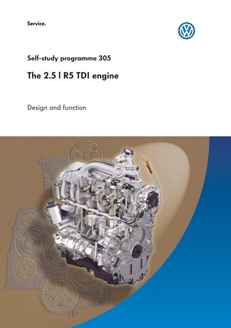
Service.<br />
Self-study programme 305<br />
<strong>The</strong> <strong>2.5</strong> l <strong>R5</strong> <strong>TDI</strong> <strong>engine</strong><br />
Design and function
2<br />
<strong>The</strong> <strong>2.5</strong> l 5-cylinder in-line <strong>TDI</strong> <strong>engine</strong> with pump<br />
injection system represents a new generation of<br />
5-cylinder diesel <strong>engine</strong>s.<br />
<strong>The</strong> primary development goal was to use the<br />
<strong>engine</strong> in various models (transverse and<br />
longitudinal mounting) with a high power<br />
density.<br />
Transporter 2004 – transverse mounting<br />
This self-study programme shows the design<br />
and function of new developments!<br />
<strong>The</strong> contents will not be updated.<br />
For the latest testing, adjustment and repair<br />
instructions, please refer to the relevant<br />
service literature.<br />
<strong>The</strong> <strong>engine</strong> is used in the Transporter 2004 with<br />
an output of 96 kW and 128 kW, and in the<br />
Touareg with an output of 128 kW.<br />
<strong>The</strong> <strong>engine</strong>s in the Transporter 2004 and in the<br />
Touareg differ particularly in respect to their<br />
adaptations for transverse and longitudinal<br />
mounting.<br />
305_018 305_038<br />
Touareg – longitudinal mounting<br />
We will present to you the design and function of the new <strong>2.5</strong> l <strong>R5</strong> <strong>TDI</strong> <strong>engine</strong> on the following pages.<br />
NEW Important<br />
Note
Contents<br />
Introduction . . . . . . . . . . . . . . . . . . . . . . . . . . . . . . . . . . . . . . . . . . 4<br />
Technical features . . . . . . . . . . . . . . . . . . . . . . . . . . . . . . . . . . . . . . . . 4<br />
Technical data . . . . . . . . . . . . . . . . . . . . . . . . . . . . . . . . . . . . . . . . . . 5<br />
Engine mechanics . . . . . . . . . . . . . . . . . . . . . . . . . . . . . . . . . . . . . 6<br />
Cylinder block . . . . . . . . . . . . . . . . . . . . . . . . . . . . . . . . . . . . . . . . . . . 6<br />
Warp anchor principle . . . . . . . . . . . . . . . . . . . . . . . . . . . . . . . . . . . 7<br />
Cylinder head . . . . . . . . . . . . . . . . . . . . . . . . . . . . . . . . . . . . . . . . . . . 8<br />
Pump injectors . . . . . . . . . . . . . . . . . . . . . . . . . . . . . . . . . . . . . . . . . . 9<br />
Crankshaft . . . . . . . . . . . . . . . . . . . . . . . . . . . . . . . . . . . . . . . . . . . . . 10<br />
Pistons and conrods . . . . . . . . . . . . . . . . . . . . . . . . . . . . . . . . . . . . . . 1 1<br />
Gear train . . . . . . . . . . . . . . . . . . . . . . . . . . . . . . . . . . . . . . . . . . . . . . 12<br />
Ancillary units drive . . . . . . . . . . . . . . . . . . . . . . . . . . . . . . . . . . . . . . 13<br />
Oil filter module . . . . . . . . . . . . . . . . . . . . . . . . . . . . . . . . . . . . . . . . . 15<br />
Oil pump . . . . . . . . . . . . . . . . . . . . . . . . . . . . . . . . . . . . . . . . . . . . . . . 16<br />
Coolant circuit . . . . . . . . . . . . . . . . . . . . . . . . . . . . . . . . . . . . . . . . . . 18<br />
Fuel system . . . . . . . . . . . . . . . . . . . . . . . . . . . . . . . . . . . . . . . . . . . . 20<br />
Exhaust system . . . . . . . . . . . . . . . . . . . . . . . . . . . . . . . . . . . . . . . . 22<br />
Exhaust gas recirculation cooler . . . . . . . . . . . . . . . . . . . . . . . . . . 24<br />
Engine management . . . . . . . . . . . . . . . . . . . . . . . . . . . . . . . . . . 26<br />
System overview . . . . . . . . . . . . . . . . . . . . . . . . . . . . . . . . . . . . . . . . 26<br />
Functional diagram . . . . . . . . . . . . . . . . . . . . . . . . . . . . . . . . . . . . . 28<br />
Service . . . . . . . . . . . . . . . . . . . . . . . . . . . . . . . . . . . . . . . . . . . . 30<br />
Test your knowledge . . . . . . . . . . . . . . . . . . . . . . . . . . . . . . . . . 32<br />
3
4<br />
Introduction<br />
Technical features<br />
<strong>The</strong> <strong>engine</strong> is a new development.<br />
<strong>The</strong> development goals were:<br />
– compact design to allow longitudinal and<br />
transverse mounting<br />
– performance gain to 128 kW<br />
– low weight, for example by using an<br />
aluminium cylinder block<br />
– low maintenance requirements, for example<br />
by using a maintenance free gear train<br />
– soiling resistant ancillary units drive<br />
– low number of sealing faces, for example by<br />
using a modular design<br />
– Crossflow cylinder head with pump injection<br />
system<br />
Technical features - <strong>engine</strong> mechanics<br />
– Cylinder block with plasma-coated<br />
cylinder faces<br />
– Single plane gear train with short installation<br />
length<br />
– Crossflow cylinder head<br />
– Crankshaft with integral vibration damper<br />
– Upright oil filter module with paper filter<br />
element and integrated oil cooler<br />
– <strong>The</strong> 3-phase AC alternator and the<br />
air conditioner compressor are driven by<br />
elastic drive couplings<br />
– Exhaust gas recirculation<br />
Technical features - <strong>engine</strong> management<br />
– Torque-oriented Bosch EDC 16 <strong>engine</strong><br />
management system<br />
– Pump injection system<br />
– Variable geometry turbocharger<br />
(electro-pneumatic)<br />
305_055
Technical data<br />
Power/torque graph<br />
Output (kW)<br />
<strong>2.5</strong> l/96 kW – AXD<br />
Speed (rpm)<br />
Torque (Nm)<br />
305_017<br />
<strong>2.5</strong> l/128 kW – AXE and BAC<br />
305_001<br />
Engine codes AXD Transporter 2004 AXE Transporter 2004<br />
BAC Touareg - longitudinal mounting<br />
Type 5-cylinder in-line <strong>engine</strong><br />
Displacement 2460 cm 3<br />
Bore 81 mm<br />
Stroke 95.5 mm<br />
Compression ratio 18.0 : 1<br />
Valves per cylinder 2<br />
Firing order 1 - 2 - 4 - 5 - 3<br />
Max. output 96 kW at 3500 rpm 128 kW at 3500 rpm<br />
Max. torque 340 Nm at 2000 rpm 400 Nm at 2000 rpm<br />
Engine management Bosch EDC 16<br />
Idling speed 800 rpm<br />
Fuel Diesel (minimum 49 CN)<br />
Exhaust gas aftertreatment Exhaust gas recirculation, main catalyst<br />
Exhaust emission standard EU 3<br />
Output (kW)<br />
Speed (rpm)<br />
<strong>The</strong> performance difference between the 96 kW variant and the 128 kW variant is due to<br />
software modifications to the <strong>engine</strong> control unit and differences in the design<br />
of the exhaust gas turbocharger.<br />
Torque (Nm)<br />
5
6<br />
Engine mechanics<br />
Cylinder block<br />
<strong>The</strong> cylinder block is made from a high-strength<br />
aluminium alloy using the low pressure<br />
permanent mould casting method.<br />
<strong>The</strong> cylinder blocks for the Transporter 2004 and<br />
the Touareg differ in particular in respect to their<br />
starter configuration.<br />
– Where the <strong>engine</strong> is transversely mounted<br />
(Transporter 2004), the starter is mounted on<br />
the gearbox side.<br />
– Where the <strong>engine</strong> is longitudinally mounted<br />
(Touareg), the starter is mounted on the<br />
<strong>engine</strong> side - which is why a starter mounting<br />
is cast on here. 305_007<br />
Plasma-coated cylinder faces<br />
<strong>The</strong> cylinder faces of the <strong>2.5</strong> l <strong>R5</strong> <strong>TDI</strong> <strong>engine</strong> are<br />
plasma-coated. This means that a coating<br />
powder is applied to the cylinder wall with a<br />
plasma burner. As a result, there is no need for<br />
cylinder liners in the aluminium cylinder block.<br />
This has the following advantages:<br />
– weight reduction compared to press-fitted<br />
cylinder liner made from grey cast iron<br />
– more compact dimensions due to a<br />
smaller distance between the cylinder bores<br />
than in the previous production <strong>engine</strong> with<br />
grey cast iron cylinder block<br />
– reduced wear through use of the plasmacoated<br />
cylinder face<br />
Plasma jet with<br />
coating powder<br />
Cylinder face<br />
Plasma burner<br />
305_019
Warp anchor principle<br />
To avoid stresses and to ensure an optimal<br />
cylinder shape, the cylinder head and the<br />
cylinder block are bolted together by tie bolts.<br />
<strong>The</strong> connection is made by means of sliding<br />
sleeves in the cylinder block. <strong>The</strong> sliding sleeves<br />
are placed in the cylinder block and locked<br />
against rotation.<br />
<strong>The</strong> sliding sleeve accepts the cylinder head bolt<br />
from one side and the tie bolt from the other<br />
side.<br />
Cylinder head bolt<br />
Cylinder head bolt<br />
Sliding sleeve<br />
Cylinder block<br />
Tie bolt<br />
305_022<br />
<strong>The</strong> removal and installation procedures, as well as the tightening sequence of the warp<br />
anchors and cylinder head bolts, are described in the workshop manual.<br />
Cylinder head<br />
305_006<br />
7
8<br />
Engine mechanics<br />
Cylinder head<br />
<strong>The</strong> aluminium cylinder head has been<br />
developed as a crossflow cylinder head. This<br />
means that the intake port and exhaust ports are<br />
arranged opposite each other in the cylinder<br />
head. This ensures an efficient charge cycle, and<br />
therefore improved cylinder charging.<br />
All control elements, such as the valves, tappets<br />
and rocker levers, have been adopted from<br />
other pump injector <strong>engine</strong>s.<br />
Pump injector<br />
Glow plug<br />
Cable routing<br />
Exhaust port<br />
Fuel rail<br />
Inlet port<br />
305_021<br />
305_020<br />
Electrical plug connector<br />
for pump injectors
Pump injectors<br />
<strong>The</strong> second generation pump injectors used previously in the 1.9 l <strong>TDI</strong> <strong>engine</strong> are installed<br />
in the <strong>2.5</strong> l <strong>R5</strong> <strong>TDI</strong> <strong>engine</strong>. <strong>The</strong>y have been adapted in respect to jet position and flow.<br />
<strong>The</strong>y have the following notable features:<br />
– a low-friction drive<br />
– an elevated injection pressure in the part-throttle range<br />
– a compact solenoid valve<br />
To keep drive friction to a minimum, the adjusting<br />
screw has a rounded end and the pressure pin<br />
has a ball socket. <strong>The</strong> large radii ensure a low<br />
surface pressure. In addition, the <strong>engine</strong> oil<br />
collects in the ball socket and thus provides good<br />
lubrication between the adjusting screw and the<br />
pressure pin.<br />
Adjusting screw<br />
Ball socket<br />
Pressure pin<br />
Solenoid valve<br />
305_029<br />
Balancer piston<br />
Inlet bore<br />
Injector<br />
spring<br />
<strong>The</strong> injection pressure in the part-throttle range<br />
has been increased by using a balancer piston<br />
with a longer stroke.<br />
<strong>The</strong> pressure in the injector spring chamber rises<br />
due to the long stroke of the balancer piston and<br />
the flow-restricting action of the inlet bore<br />
between the injector spring chamber and the<br />
fuel duct. <strong>The</strong> injector spring is preloaded still<br />
further and the injection pressure increases.<br />
High pressure<br />
chamber<br />
305_030<br />
Fuel return line<br />
Fuel supply line<br />
9
10<br />
Engine mechanics<br />
Crankshaft<br />
To achieve a short installation length, the<br />
vibration damper is integrated in the crankshaft.<br />
Vibration damper<br />
If the crankshaft is removed, the<br />
cylinder head must also be dismounted<br />
and the cylinder head gasket replaced.<br />
Please refer to the workshop manual.<br />
<strong>The</strong> vibration damper is mounted to crankshaft<br />
by four bolts in lieu of the first counterweight.<br />
Vibrations are damped over the full <strong>engine</strong> load<br />
and <strong>engine</strong> speed range by plastic friction<br />
elements.<br />
Engine speed sender wheel<br />
<strong>The</strong> gear for driving the gear train is pressed<br />
fitted onto the output end of the crankshaft.<br />
<strong>The</strong> sender wheel is machined as part of the<br />
crankshaft assembly. This eliminates additional<br />
assembly tolerances in the sender wheel and<br />
enhances the accuracy of the signal for <strong>engine</strong><br />
speed measurement.<br />
<strong>The</strong> vibration damper can be<br />
replaced without having to remove<br />
the crankshaft by detaching the first<br />
conrod bearing cap.<br />
Sender wheel<br />
Vibration<br />
damper<br />
Vibration damper<br />
Gear train drive gear<br />
Sender wheel<br />
Fastening bolt<br />
305_023<br />
305_025<br />
305_024
Conrods and pistons<br />
Pistons<br />
<strong>The</strong> piston bosses and the small end have a<br />
trapezoidal shape in order to minimise the<br />
stresses in the pistons and conrods under high<br />
combustion pressures. As a result, the<br />
combustion forces are distributed over a larger<br />
area. To provide good antifrictional properties,<br />
the piston bosses have brass bushings.<br />
A cooling duct has been cast into the piston in<br />
order to cool the piston ring zone. <strong>The</strong> oil spray<br />
nozzles inject oil into this cooling duct as soon as<br />
the piston is located at bottom dead center.<br />
Conrod<br />
<strong>The</strong> single-piece conrod is made by forging.<br />
<strong>The</strong> connecting rod cap is made by cracking.<br />
Piston pin axis offset<br />
<strong>The</strong> piston pin axis is arranged excentrically in<br />
order to eliminate noises caused by tilting of the<br />
piston at top dead centre.<br />
Whenever the connecting rod is inclined, lateral<br />
piston forces which alternately press the piston<br />
against the cylinder wall are produced.<br />
<strong>The</strong> lateral piston force changes direction at top<br />
dead centre. Here the piston is tilted towards the<br />
opposed cylinder wall and produces noises.<br />
To prevent tilting of the piston and the resulting<br />
noises, the piston pin axis is arranged<br />
excentrically.<br />
By offsetting the piston pin axis, the piston<br />
changes sides before it reaches top dead centre<br />
and rests against the opposite cylinder wall.<br />
Cooling duct<br />
Brass bushing<br />
Trapezoidal<br />
small end<br />
305_026<br />
305_027<br />
Top dead centre Cylinder axis<br />
Piston pin axis<br />
305_028<br />
11
12<br />
Engine mechanics<br />
Gear train<br />
Due to the constraints on space, particularly in vehicles with transversely mounted <strong>engine</strong>s, a helical<br />
gear train is used. <strong>The</strong> gear train transmits the high drive forces in a space-saving manner. A 15° helical<br />
toothing increases the load-bearing tooth flank width and reduces the gear dimensions to a minimum.<br />
<strong>The</strong> gear train is arranged on the flywheel end. <strong>The</strong> camshaft and the ancillary units are driven by the<br />
crankshaft via the gear train.<br />
<strong>The</strong> backlash in relation<br />
to the camshaft gear is<br />
set with the adjustable<br />
intermediate gear<br />
305_051<br />
Clamp<br />
T10199<br />
Tension gear<br />
Drive gear for vane pump<br />
for power steering and<br />
air conditioner compressor<br />
Camshaft gear<br />
Intermediate gear<br />
(adjustable)<br />
Alternator<br />
driving gear<br />
Intermediate<br />
gear<br />
Oil pump<br />
drive gear<br />
<strong>The</strong> gear train is maintenance free.<br />
Provision is not made for replacement of gears by after-sales service.<br />
Intermediate sprokket<br />
305_003<br />
Camshaft gear<br />
Coolant pump gear<br />
Intermediate<br />
gear
Ancillary units drive<br />
<strong>The</strong> ancillary units are driven directly by the gear train.<br />
In the alternator and air conditioner compressor, the axis offset tolerances as well as the running<br />
irregularities in the longitudinal direction of the drive axis are equalised and damped by an elastic<br />
drive coupling.<br />
A further advantage is that this coupling not as prone to soiling. This is particularly important for offroad<br />
driving and in dusty countries.<br />
When removing the alternator, do<br />
not take apart the bracket and the<br />
alternator.<br />
Air conditioner<br />
compressor<br />
Alternator Freewheel<br />
Freewheel<br />
Elastic drive<br />
coupling<br />
305_002<br />
305_053<br />
Elastic drive<br />
coupling<br />
Alternator bracket<br />
Alternator<br />
Alternator drive gear<br />
Tension gear (two-piece)<br />
Drive gear of<br />
vane pump for power steering,<br />
air conditioner compressor<br />
Vane pump for power steering<br />
13
14<br />
Engine mechanics<br />
Elastic drive coupling<br />
<strong>The</strong> elastic drive coupling comprises two geared<br />
metal hubs which are mechanically connected<br />
via a coupling belt.<br />
Tension gear<br />
Hub<br />
<strong>The</strong> task of the tension gear is to reduce the<br />
backlash of the gears which drive the ancillary<br />
units. <strong>The</strong> tension gear is a two-part construction.<br />
Both parts are connected by a torsion spring<br />
located between the two parts of the gear.<br />
Bush<br />
Coupling belt<br />
Hub<br />
305_014<br />
Preloading the torsion springs causes the parts of<br />
the gear to counterrotate. <strong>The</strong> backlash of the<br />
tension gear and meshing gears is thereby<br />
reduced.<br />
Tension gear<br />
Torsion spring<br />
Washer<br />
Circlip<br />
305_056
Oil filter module<br />
<strong>The</strong> oil filter module is mounted to the cylinder<br />
block by five bolts. It comprises an upright oil<br />
filter and an integrated oil cooler.<br />
<strong>The</strong> oil filter element is replaced in the upward<br />
direction.<br />
Advantages of the oil filter module<br />
– Sealing face with 5-point threaded connection<br />
– Eco-friendly upright oil filter with paper<br />
element<br />
– Integrated oil cooler<br />
Oil filter<br />
Oil filter<br />
Oil cooler<br />
Oil cooler<br />
305_032<br />
305_033<br />
15
16<br />
Engine mechanics<br />
Oil pump<br />
<strong>The</strong> Duocentric oil pump is bolted to the base of<br />
the cylinder block and driven by the crankshaft<br />
via gears.<br />
<strong>The</strong> oil pump is located by two fitted<br />
sleeves in the cylinder block. Please<br />
refer to the workshop manual.<br />
Oil circuit supply line<br />
Oil pump drive gear<br />
305_046<br />
Camshaft gear<br />
A special feature of the oil circuit is that the warp anchor holes are integrated in the oil supply line.<br />
Various bearing points and the gear train are supplied with oil through the warp anchor holes.<br />
Warp anchor hole<br />
305_044
Oil circuit return line<br />
<strong>The</strong> oil mainly flows back from the cylinder head in the area of the gear train.<br />
A further portion of the oil flows back into the oil sump through return bores on both side walls of the<br />
<strong>engine</strong>.<br />
Oil return in the area of<br />
gear train<br />
Oil sump<br />
305_045<br />
Return bore<br />
17
18<br />
Engine mechanics<br />
Coolant circuit<br />
<strong>The</strong> figure shows the coolant circuit of the Transporter 2004 with an supplementary coolant heater.<br />
Various variants are used depending on specification.<br />
Key<br />
1<br />
2<br />
3<br />
4<br />
5<br />
6<br />
7<br />
First heat exchanger<br />
Coolant thermostat (opens when coolant<br />
temperature exceeds 80 °C)<br />
Cylinder head<br />
Exhaust gas recirculation cooler<br />
Coolant pump<br />
Cooler<br />
Oil cooler<br />
8<br />
9<br />
10<br />
11<br />
12<br />
13<br />
14<br />
15<br />
305_008<br />
Cylinder block<br />
Vent pipe<br />
Expansion tank<br />
Heater coolant shut-off valve N279<br />
Non-return valve<br />
Second heat exchanger (for rear passenger<br />
compartment)<br />
Supplementary coolant heater<br />
Recirculation pump
Coolant pump<br />
<strong>The</strong> coolant pump is designed as a vane pump<br />
and is inserted into the cylinder block on the spur<br />
gear side. It is driven via gears of the gear train.<br />
<strong>The</strong> coolant pump can be removed without<br />
dismantling the gear train housing.<br />
Bolt<br />
Before removing the coolant pump, the<br />
coolant must be drained at the coolant<br />
drain plugs. This prevents coolant from<br />
flowing into the gear train housing and<br />
oil sump and mixing with the <strong>engine</strong> oil.<br />
Cover<br />
Nut<br />
Gear<br />
Securing bolt<br />
Gear train<br />
housing<br />
Coolant pump<br />
Coolant pump<br />
Special tools are used for removing the coolant pump:<br />
coolant pump spur gear puller T10221 and coolant pump puller T10222.<br />
305_049<br />
Coolant drain plug<br />
305_050<br />
19
20<br />
Engine mechanics<br />
Fuel system<br />
<strong>The</strong> overview shows the fuel system of the<br />
Transporter 2004.<br />
Fuel line<br />
for supplementary coolant<br />
heater<br />
Fuel tank<br />
<strong>The</strong> electrical fuel pump in the tank serves as a<br />
pre-supply pump, and pumps fuel to the fuel<br />
filter.<br />
<strong>The</strong> non-return valve prevents fuel from flowing<br />
fuel back from the fuel rail and supply line into<br />
the fuel tank when the <strong>engine</strong> is stopped.<br />
Low pressure fuel<br />
supply line<br />
Electric<br />
fuel pump<br />
Fuel cooler<br />
Fuel filter<br />
Non-return valve<br />
Fuel supply pressure<br />
regulating valve<br />
Fuel temperature<br />
sender<br />
Fuel pump<br />
<strong>The</strong> fuel filter protects the injection system<br />
against soiling and wear by particles and water.<br />
<strong>The</strong> fuel pump pumps the fuel out of the fuel filter<br />
and into the fuel supply line under high pressure.
Fuel return pressure<br />
limiting valve<br />
Fuel return line<br />
<strong>The</strong> pressure regulating valve sets the fuel<br />
pressure in the fuel supply line to approximately<br />
8.5 bar.<br />
<strong>The</strong> pressure limiting valve limits the fuel<br />
pressure in the fuel return line to approximately<br />
1 bar. <strong>The</strong> pressure conditions in the fuel system<br />
are thus balanced.<br />
<strong>The</strong> fuel cooler cools the flowing back fuel in<br />
order to protect the fuel tank against excessively<br />
hot fuel.<br />
High pressure fuel<br />
supply line<br />
Fuel rail<br />
Pump injector<br />
Return Low pressure supply line High pressure supply line<br />
<strong>The</strong> fuel temperature sender measures the fuel<br />
temperature for the <strong>engine</strong> control unit.<br />
<strong>The</strong> pump injectors are solenoid valves that are<br />
activated by the <strong>engine</strong> control unit. <strong>The</strong>y are<br />
used to control the commencement of injection<br />
and injection quantity.<br />
305_037<br />
21
22<br />
Engine mechanics<br />
Exhaust system<br />
<strong>The</strong> exhaust system comprises an exhaust manifold, a main catalyst, a front silencer and a rear silencer.<br />
Exhaust manifold<br />
<strong>The</strong> exhaust manifold is an insulated sheet metal manifold with a gas-tight inner shell. This highly<br />
compact design ensures a high rate of heating. Additional heat shielding is not required.<br />
Exhaust manifold<br />
insulation<br />
Exhaust manifold<br />
inner shells<br />
Exhaust manifold<br />
insulation<br />
305_047
Overview of the exhaust system<br />
<strong>The</strong> overview shows the components of the exhaust system in the Transporter 2004.<br />
Main catalytic converter<br />
Front silencer<br />
Rear silencer<br />
305_031<br />
23
24<br />
Engine mechanics<br />
Exhaust gas recirculation cooler<br />
An exhaust gas recirculation cooler is used in several variants in order to lower the combustion<br />
temperature, and thus reduce nitrogen oxide emissions and soot formation.<br />
Variants:<br />
– An exhaust gas recirculation cooler, which<br />
continuously cools the exhaust gas, is used<br />
in the Transporter 2004 with automatic<br />
transmission and in the Touareg with manual<br />
gearbox.<br />
Exhaust gas<br />
recirculation cooler<br />
305_054<br />
– A switchable exhaust gas recirculation cooler,<br />
which cools the exhaust gas at a coolant<br />
temperature upwards of approximately 50 °C,<br />
is used in the Touareg with automatic<br />
transmission.
How the switchable exhaust gas recirculation cooler works<br />
A switchable exhaust gas recirculation cooler is used, because continuous cooling of the recirculated<br />
exhaust gases results in higher hydrocarbon and carbon monoxide emissions.<br />
<strong>The</strong> exhaust gas is ducted either through the cooler or past the cooler to the exhaust gas recirculation<br />
valve.<br />
Without exhaust gas cooling<br />
<strong>The</strong> exhaust flap remains closed up to a coolant temperature of approximately 50 °C, and the exhaust<br />
gas bypasses the cooler.<br />
By the coolant<br />
temperature sender G62<br />
With exhaust gas cooling<br />
<strong>The</strong> exhaust flap is opened by the exhaust gas recirculation cooler change-over valve at a coolant<br />
temperature of approximately 50 °C. <strong>The</strong> recirculated exhaust gas now flows through the cooler. <strong>The</strong><br />
cooling capacity depends on the coolant temperature and the exhaust gas recirculation rate.<br />
Exhaust gas recirculation<br />
cooler change-over valve<br />
N345<br />
Engine control unit<br />
J623<br />
To the exhaust gas<br />
turbocharger<br />
From exhaust manifold<br />
Exhaust gas recirculation cooler<br />
Coolant<br />
Vacuum unit<br />
not operated<br />
Exhaust flap<br />
To EGR valve<br />
305_057<br />
Vacuum unit<br />
operated<br />
305_058<br />
25
26<br />
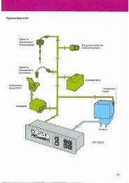
Engine management<br />
System overview<br />
<strong>The</strong> Bosch EDC 16 Electronic Diesel Control is used in combination with a torque-oriented <strong>engine</strong><br />
management system in the <strong>2.5</strong> l <strong>R5</strong> <strong>TDI</strong> <strong>engine</strong> in the Transporter 2004 and in the Touareg.<br />
Sensors<br />
Engine speed sender G28<br />
Hall sender G40<br />
Accelerator position sender G79<br />
Kick-down switch F8<br />
Idling switch F60<br />
Air mass flow meter G70<br />
Coolant temperature sender G62<br />
Coolant temperature sender<br />
- radiator outlet G83<br />
Fuel temperature sender G81<br />
Charge air pressure sender G31<br />
Intake air temperature sender G42<br />
Brake light switch F<br />
Brake pedal switch F47<br />
Clutch pedal switch F36<br />
Additional input signals<br />
Diagnosis<br />
connection<br />
Engine control unit J623<br />
CAN drive train data bus
You will find a detailed description of the <strong>engine</strong> management system in Self-Study Programme 304<br />
"<strong>The</strong> EDC 16 Electronic Diesel Control".<br />
* Used in the Touareg<br />
** Used in the Touareg with automatic<br />
transmission<br />
305_011<br />
Actuators<br />
Pump injector valves N240 … N244<br />
Fuel pump relay J17<br />
Fuel pump (pre-supply pump) G6<br />
Fuel pump G23 *<br />
Exhaust gas recirculation valve N18<br />
Charge pressure control solenoid<br />
valve N75<br />
Coolant pump run-on relay J151<br />
Recirculation pump V55<br />
Fuel cooling pump relay J445 *<br />
Fuel cooling pump V166 *<br />
Intake manifold flap change-over valve N239<br />
Exhaust gas recirculation cooler<br />
change-over valve N345 **<br />
Glow plug relay J52<br />
Glow plugs Q10 … Q14<br />
Additional output signals<br />
27
30<br />
15<br />
31<br />
28<br />
Engine management<br />
A<br />
Functional diagram<br />
<strong>2.5</strong> l <strong>R5</strong> <strong>TDI</strong> <strong>engine</strong> with the EDC 16 in the Transporter 2004 and Touareg<br />
+<br />
-<br />
J317<br />
N240 N241 N242 N243 N244 G81<br />
Additional signals<br />
1<br />
2<br />
3<br />
4<br />
N239 N75<br />
N345<br />
G62 G83<br />
Drive train CAN data bus<br />
Drive train CAN data bus<br />
Communications line (diagnostic connection)<br />
Road speed signal<br />
N18<br />
J151<br />
M<br />
V55<br />
+<br />
J623<br />
J445<br />
M<br />
V166<br />
J52<br />
Q10...Q14<br />
G31 G42 G40 G28 F60/F8 G79<br />
5<br />
6<br />
7<br />
8<br />
Alternator terminal DFM<br />
Cruise control system switch<br />
(ON/OFF)<br />
Radiator fan - 1st speed<br />
Radiator fan - 2nd speed<br />
F36
F47 F<br />
A<br />
G70<br />
A<br />
A<br />
J17<br />
1<br />
2<br />
3<br />
M<br />
4 5<br />
G23<br />
M<br />
G6<br />
6 7 8<br />
305_012<br />
Connection within the function diagram<br />
30<br />
15<br />
31<br />
Key<br />
A Battery<br />
F Brake light switch<br />
F8 Kick-down switch<br />
F36 Clutch pedal switch<br />
F47 Brake pedal switch<br />
F60 Idling switch<br />
G6 Fuel pump (pre-supply pump)<br />
G23 Fuel pump *<br />
G28 Engine speed sender<br />
G31 Charge air pressure sender<br />
G40 Hall sender<br />
G42 Intake air temperature sender<br />
G62 Coolant temperature sender<br />
G70 Air mass meter<br />
G79 Accelerator position sender<br />
G81 Fuel temperature sender<br />
G83 Coolant temperature sender -<br />
radiator outlet<br />
J17 Fuel pump relay<br />
J52 Glow plug relay<br />
J151 Coolant pump run-on relay<br />
J317 Voltage supply relay - Term. 30<br />
J445 Fuel cooling pump relay *<br />
J623 Engine control unit<br />
N18 Exhaust gas recirculation valve<br />
N75 Charge pressure control solenoid valve<br />
N239 Intake manifold flap change-over valve<br />
N240 Injector solenoid valve, No. 1 cyl.<br />
N241 Injector solenoid valve, No. 2 cyl.<br />
N242 injector solenoid valve, No. 3 cyl.<br />
N243 injector solenoid valve, No. 4 cyl.<br />
N244 Injector solenoid valve, No. 5 cyl.<br />
N345 Exhaust gas recirculation cooler<br />
change-over valve **<br />
Q10 Glow plug -1-<br />
Q11 Glow plug -2-<br />
Q12 Glow plug -3-<br />
Q13 Glow plug -4-<br />
Q14 Glow plug -5-<br />
V55 Recirculation pump<br />
V166 Fuel cooling pump *<br />
* Used in the Touareg<br />
** Used in the Touareg with automatic transmission<br />
29
30<br />
Service<br />
Designation Special tool<br />
Clamp<br />
T10199<br />
Engine holder for assembly stand<br />
T10220<br />
Coolant pump spur gear puller<br />
T10221<br />
Coolant pump puller<br />
T10222<br />
305_052<br />
305_042<br />
305_039<br />
305_041
Designation Special tool<br />
Clutch centring mandrel<br />
T10223<br />
Engine holder for <strong>engine</strong> and<br />
gearbox lifter (removal and<br />
installation)<br />
T10224<br />
Key for turning the <strong>engine</strong><br />
T10225<br />
Crankshaft locating tool<br />
T10226<br />
Graphic unavailable at time of going to press<br />
Graphic unavailable at time of going to press<br />
305_043<br />
305_040<br />
31
32<br />
Test your knowledge<br />
Which of the following answers is correct?<br />
One or more, or even all, answers may be correct.<br />
1. What were the prescribed development goals for the <strong>2.5</strong> l <strong>R5</strong> <strong>TDI</strong> <strong>engine</strong>?<br />
a) A low weight, for example by using an aluminium cylinder block.<br />
b) A compact design to allow transverse and longitudinal mounting.<br />
c) Low maintenance requirements, for example by using a maintenance free gear train.<br />
2. What are the special features of the crankshaft?<br />
a) <strong>The</strong> <strong>engine</strong> speed sender wheel is bolted on.<br />
b) <strong>The</strong> vibration damper is integrated in the crankshaft.<br />
c) <strong>The</strong> vibration damper can be replaced without removing the crankshaft.<br />
3. Which of the following statements on the gear train is true?<br />
a) <strong>The</strong> backlash of the camshaft gear is adjustable.<br />
b) <strong>The</strong> gear train is designed to save weight.<br />
c) High drive forces can be transmitted in a space-saving manner by using gears.
4. Which of the following statements on the ancillary units is true?<br />
a) <strong>The</strong> ancillary units are driven by the gear train.<br />
b) In the alternator and air conditioner compressor, the axle offset tolerances and the running<br />
irregularities in the longitudinal direction are equalised and damped by an elastic drive<br />
coupling.<br />
c) <strong>The</strong> alternator and the bracket may only be removed completely, and must not<br />
be taken apart.<br />
5. What are the points which must be observed before removing the coolant pump?<br />
a) <strong>The</strong> coolant must be drained at the coolant drain plugs before removing the coolant pump.<br />
b) <strong>The</strong> coolant pump can be removed without dismantling the gear train housing.<br />
c) <strong>The</strong> gear train housing must be removed before removing the coolant pump.<br />
6. Which <strong>engine</strong> management system is used?<br />
a) <strong>The</strong> EDC 15 Electronic Diesel Control.<br />
b) <strong>The</strong> EDC 16 Electronic Diesel Control with torque-oriented <strong>engine</strong> management.<br />
c) <strong>The</strong> EDC 16 Electronic Diesel Control without torque-oriented <strong>engine</strong> management.<br />
33
34<br />
Notes<br />
Answers<br />
1. a, b, c; 2. b, c; 3. a, c; 4. a, b, c; 5. a, b; 6. b
For internal use only © VOLKSWAGEN AG, Wolfsburg<br />
All rights and the right to make technical alterations reserved<br />
000.2811.25.20 Technical status 03/03<br />
❀ This paper was manufactured from pulp that<br />
was bleached without the use of chlorine.<br />
305