A Low-Power Tunable SiGe HBT LNA for Wireless LAN Applications
A Low-Power Tunable SiGe HBT LNA for Wireless LAN Applications
A Low-Power Tunable SiGe HBT LNA for Wireless LAN Applications

Create successful ePaper yourself
Turn your PDF publications into a flip-book with our unique Google optimized e-Paper software.
A <strong>Low</strong>-<strong>Power</strong> <strong>Tunable</strong> <strong>SiGe</strong> <strong>HBT</strong> <strong>LNA</strong> <strong>for</strong> <strong>Wireless</strong> <strong>LAN</strong> <strong>Applications</strong><br />
Corrado Carta, Jörg Carls and Werner Bächtold<br />
Electromagnetic Fields and Microwave Electronics Laboratory (IFH),<br />
Swiss Federal Institute of Technology (ETH), 8092 Zurich, Switzerland<br />
email: carta@ifh.ee.ethz.ch<br />
Abstract<br />
This paper presents the design, implementation and measurements<br />
of a BiCMOS integrated tunable <strong>Low</strong> Noise Amplifier<br />
<strong>for</strong> 5 GHz W<strong>LAN</strong> applications. It consists of a cascode<br />
gain cell, noise and power matched to a 50 Ω input<br />
source, and power matched to a 50 Ω load. In order<br />
to broaden the available bandwidth, the output matching<br />
network is modified by means of a shunt varactor, thus allowing<br />
the tuning of output matching and peak gain over<br />
a band exceeding 1 GHz. The proposed topology modification<br />
proofs to have neglectable effects on other <strong>LNA</strong> features,<br />
such as noise figure, linearity and input matching.<br />
Realized in a 120 GHz-ft commercial BiCMOS technology,<br />
the circuit exhibits 13.2 dB of flat power gain, 2.3 dB of NF,<br />
-9 dBm of iIP3, -20.5 dBm of P1 dBm, input and output return<br />
losses better than -10 dB in the 5-6 GHz band. <strong>Power</strong><br />
consumption is 6 mW.<br />
1. Introduction<br />
The 5-6 GHz wireless <strong>LAN</strong> standards make use of<br />
three unlicensed U-NII bands, resulting in a total input<br />
band from 5.15 GHz to 5.875 GHz [5]. This sets the<br />
operating bandwidth of the first receiver stages, including<br />
the <strong>LNA</strong>. In designing this building block, cascode amplifiers<br />
are often preferred as gain cell because of their good<br />
isolation and voltage gain; one drawback this choice implies<br />
is that achieving sufficient preamplifier bandwidth<br />
becomes difficult, even with low-quality silicon technologies:<br />
the problem is typically addressed designing the receiver<br />
<strong>for</strong> the two lower [5–7] or the upper [2, 4] U-NII<br />
bands, or lowering the resonator quality factors, thus trading<br />
gain <strong>for</strong> bandwidth [1].<br />
Assuming that no more than one 20 MHz channel would<br />
be received at a time, this paper presents an alternative<br />
approach: with a simple modification of typical<br />
<strong>LNA</strong> topologies, output matching and power gain can be<br />
tuned and optimized over a band sufficient to cover com-<br />
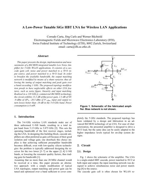
Vtune R∞<br />
RFin<br />
L2<br />
Ctune<br />
Vbias<br />
C1<br />
C∞<br />
Vcc<br />
T2<br />
T1<br />
L3<br />
L1<br />
C2<br />
RFout<br />
Figure 1. Schematic of the fabricated amplifier.<br />
Bias network is not shown.<br />
pletely the 5 GHz standards. The proposed topology has<br />
been validated by a design and fabrication in an advanced<br />
BiCMOS technology of an <strong>LNA</strong>. For ease of characterization,<br />
the presented amplifier is designed to drive a<br />
50 Ω load, but the same idea can be easily adapted to the<br />
higher impedance levels typical <strong>for</strong> on-chip system designs.<br />
2. Circuit<br />
2.1. Design<br />
Fig. 1 shows the schematic of the amplifier. The <strong>LNA</strong><br />
is a single-ended <strong>HBT</strong> cascode, power matched to 50 Ω at<br />
both input and output; the input matching network was designed<br />
to achieve simultaneous noise and power matching<br />
[8] to the source.<br />
The cascode gain cell is often chosen <strong>for</strong> W<strong>LAN</strong> re-
ceivers: this is mainly due to its good isolation and its high<br />
output impedance, which improves the gain <strong>for</strong> given current<br />
consumption and output-matching quality factor.<br />
Both of the transistor dimensions are set <strong>for</strong> peak-ft operation<br />
at the given DC collector current. This sets the input<br />
capacity of T1: <strong>for</strong> this reason, capacitor C1 is used to increase<br />
the input capacity to a value convenient to achieve,<br />
together with inductors L1 and L2, noise and power input<br />
matching.<br />
A conventional narrow-band output matching is implemented<br />
by means of L3, Ctune and C2. The value of<br />
L3 and the nominal value of Ctune, i.e. the value <strong>for</strong><br />
Vtune = Vcc, are chosen to provide the reactance necessary<br />
<strong>for</strong> power matching at 5.5 GHz, the center frequency<br />
of the target band. The capacity variation tunes the matching<br />
center frequency and the power-gain peak.<br />
Apart from offering the tuning capability, a positive<br />
side-effect of adding Ctune in parallel to L3 is that the inductance<br />
of L3 needed <strong>for</strong> power matching is lower: this<br />
results in a smaller size of the spiral inductor and reduces<br />
the overall circuit active area.<br />
Targeting the main 5-6 GHz W<strong>LAN</strong> standards, the circuit<br />
was designed to achieve 14dB of flat gain over the<br />
whole 5-6 GHz band, a NF of 2 dB [1] with a current consumption<br />
of 3mA from a 2V power supply.<br />
2.2. Fabrication<br />
The circuit was fabricated with the commercial IBM<br />
BiCMOS 7HP process [3]. At optimum bias current, the<br />
<strong>HBT</strong>s yield transit frequencies ft up to 120 GHz and minimum<br />
noise figures of around 0.5 dB at 5-6 GHz. The process<br />
is targeted <strong>for</strong> RF, analog and mixed signal applications:<br />
a 4 µm thick Analog Metal and deep-trench insulations<br />
allow the integration of inductors with quality factors<br />
up to 20 at 5 GHz.<br />
The circuit has been implemented on a 0.3 mm 2 active area,<br />
as shown in the photograph in Fig 2. Total area shown measures<br />
1.18 mm×0.92 mm; area efficiency is mainly limited<br />
by bond pads and pattern density requirements.<br />
Transistors T1 and T2 are dual-base-contact <strong>HBT</strong>s; L1−3<br />
are single layer octagonal inductors over deep-trench lattice;<br />
Ctune is a nFET varactor, while C1−3,∞ are MIM high<br />
density capacitors.<br />
3. Measurements<br />
The circuit has been characterized on-wafer using<br />
RF probes. While biased with a 3 mA collector current,<br />
it showed similar per<strong>for</strong>mances <strong>for</strong> Vcc ranging<br />
from 1.5 V to 2.4 V. Results presented here are those observed<br />
<strong>for</strong> Vcc =2 V.<br />
Figure 2. Chip microphotograph. Area shown<br />
measures 1.18 mm×0.92 mm<br />
Table 1. Summary of experimental results<br />
Technology 120 GHz-ft BiCMOS<br />
|S21|max<br />
13.2 dB<br />
|S21|max± 0.1 dB 5.1 – 6.2 GHz<br />
|S11|
|S 21 |, |S 22 | [dB]<br />
15<br />
10<br />
5<br />
0<br />
−5<br />
−10<br />
−15<br />
−20<br />
−25<br />
3 4 5 6 7 8<br />
Frequency [GHz]<br />
Figure 3. Effects of the output-matching tuning<br />
on S21 and S22: Vcc − Vtune sweeps from<br />
-0.4 V to 0.3 V<br />
Fig. 5 presents an example of linearity tests pre<strong>for</strong>med on<br />
the <strong>LNA</strong> at 5.5 GHz: in this case, P1 dB is -20.5 dBm and<br />
iIP3 is -9 dBm at the corresponding optimum Vtune value.<br />
Extrapolations of iIP3 at other frequencies have confirmed<br />
that it is independent of Ctune variations, within measurement<br />
uncertainty.<br />
4. Conclusions<br />
The design, implementation and characterization of a<br />
tunable <strong>LNA</strong> have been presented. A simple modification<br />
of the topology <strong>for</strong> the output matching network allows<br />
to double the -10 dB bandwidth of S22 and achieves<br />
constant power gain over the 5.1-6.2 GHz band. The measured<br />
per<strong>for</strong>mances are sufficient to meet the specifications<br />
<strong>for</strong> an RF front-end compliant with the main W<strong>LAN</strong><br />
standard in the 5 GHz band [1]. In particular, the flat frequency<br />
response of the gain can significantly improve<br />
the noise per<strong>for</strong>mance of the whole receiver, or simplify<br />
the use of noise-critical active mixers relaxing, e.g.,<br />
the LO power requirements.<br />
5. Acknowledgment<br />
This work was funded by the ETH/IBM Center <strong>for</strong> Advanced<br />
Silicon Electronics (CASE).<br />
|S 21 |, NF [dB]<br />
RF output power [dBm]<br />
15<br />
12<br />
9<br />
6<br />
3<br />
NF<br />
|S 21 |<br />
|S 11 |<br />
|S 22 |<br />
−10<br />
−15<br />
−20<br />
0<br />
3 4 5 6 7 8<br />
Frequency (RF) [GHz]<br />
−25<br />
Figure 4. Optimal S-parameters and noise figure:<br />
<strong>for</strong> each frequency Vtune is set <strong>for</strong> best<br />
|S22| value.<br />
10<br />
−10<br />
−30<br />
−50<br />
−70<br />
−90<br />
−45 −40 −35 −30 −25 −20 −15 −10 −5<br />
RF input power [dBm]<br />
11<br />
1st<br />
3rd<br />
Gain<br />
11.5<br />
0<br />
−5<br />
13.5<br />
13<br />
12.5<br />
Figure 5. Linearity tests pre<strong>for</strong>med on the<br />
<strong>LNA</strong> at 5.5 GHz. Vtune is set <strong>for</strong> best |S22|<br />
value.<br />
The authors wish to thank H.-R. Benedickter and M. Lanz<br />
(both with IFH-ETH) <strong>for</strong> their valuable help in characterizing<br />
the circuit and preparing the test boards, M. Schmatz<br />
(IBM) and R. Vogt (IFH) <strong>for</strong> managing the project.<br />
References<br />
[1] C. Carta, M. Schmatz, R. Vogt, and W. Bachtold. A C-band<br />
monolithic silicon-bipolar low-power low-IF W<strong>LAN</strong> receiver.<br />
In 7th European <strong>Wireless</strong> Technology Conference (European<br />
Microwave Week), 2004.<br />
[2] S. Chakraborty, S. Reynolds, H. Ainspan, and J. Laskar. Development<br />
of 5.8GHz <strong>SiGe</strong> BiCMOS direct conversion re-<br />
12<br />
|S 11 |, |S 22 | [dB]<br />
<strong>Power</strong> gain [dB]
ceivers. In Microwave Symposium Digest, 2003 IEEE MTT-S<br />
International, volume 3, pages 1551–1554 vol.3, 2003.<br />
[3] J. Dunn. Foundation of RF CMOS and <strong>SiGe</strong> BiCMOS<br />
technologies. IBM Journal of Research and Development,<br />
47(2/3):101–138, 2003.<br />
[4] M. Hotti, J. Kaukovuori, J. Ryynanen, K. Kivekas, J. Jussila,<br />
and K. Halonen. A direct conversion RF front-end <strong>for</strong> 2-GHz<br />
WCDMA and 5.8-GHz W<strong>LAN</strong> applications. In Radio Frequency<br />
Integrated Circuits (RFIC) Symposium, 2003 IEEE,<br />
pages 45–48, 2003.<br />
[5] T. Lee, H. Samavati, and H. Rategh. 5-GHz CMOS wireless<br />
<strong>LAN</strong>s. IEEE Transactions on Microwave Theory and Techniques,<br />
50(1):268–80, 2002.<br />
[6] T.-P. Liu and E. Westerwick. 5-GHz CMOS radio transceiver<br />
front-end chipset. Solid-State Circuits, IEEE Journal of,<br />
35(12):1927–1933, 2000.<br />
[7] B. Razavi. A 5.2-GHz CMOS receiver with 62-dB image rejection.<br />
IEEE Journal of Solid-State Circuits, 36(5):810–815,<br />
2001.<br />
[8] D. Shaeffer and T. Lee. A 1.5-V, 1.5-GHz CMOS low noise<br />
amplifier. IEEE Journal of Solid State Circuits, 32(5):745–59,<br />
1997.