
You also want an ePaper? Increase the reach of your titles
YUMPU automatically turns print PDFs into web optimized ePapers that Google loves.
Principle<br />
<strong>Helium</strong> <strong>Neon</strong> <strong>Laser</strong><br />
The difference between spontaneous and stimulated emission of light is demonstrated.<br />
The beam propagation within the resonator cavity of a He-Ne laser and its divergence<br />
are determined and the relative output power of the laser is measured as a function of<br />
the tube's position inside the resonator and of the tube current.<br />
There are four main parts to this experiment:<br />
1. Set up the He-Ne laser. Adjust the resonator mirrors by use of the pilot laser.<br />
(left mirror: VIS, HR, plane; right mirror: VIS, HR, R = 1000 mm)<br />
2. Measure the output power as a function of mirror spacing.<br />
3. Measure the integral relative output power as a function of the laser tube's<br />
position within the hemispherical resonator.<br />
4. Measure the beam diameter within the hemispherical resonator right and left<br />
of the laser tube.<br />
5. Measure the integral relative output power as a function of the tube current.<br />
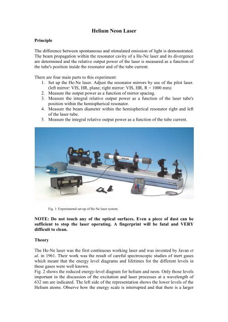
Fig. 1: Experimental set-up of He-Ne laser system.<br />
NOTE: Do not touch any of the optical surfaces. Even a piece of dust can be<br />
sufficient to stop the laser operating. A fingerprint will be fatal and VERY<br />
difficult to clean.<br />
Theory<br />
The He-Ne laser was the first continuous working laser and was invented by Javan et<br />
al. in 1961. Their work was the result of careful spectroscopic studies of inert gases<br />
which meant that the energy level diagrams and lifetimes for the different levels in<br />
these gases were well known.<br />
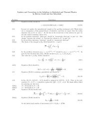
Fig. 2 shows the reduced energy-level diagram for helium and neon. Only those levels<br />
important in the discussion of the excitation and laser processes at a wavelength of<br />
632 nm are indicated. The left side of the representation shows the lower levels of the<br />
<strong>Helium</strong> atoms. Observe how the energy scale is interrupted and that there is a larger
difference in energy in the recombination process than is evident in the diagram. A<br />
characteristic of helium is that its first states to be excited, 2 1 S1 and 2 1 S0 are<br />
metastable, i.e. optical transitions to the ground state 1 1 S0 are not allowed, because<br />
this would violate the selection rules for optical transitions. Therefore by passing an<br />
electric current through the gas electron collisions can populate the 2 1 S0 level which is<br />
then long lived. Following an collision between an electron and the helium atom the<br />
helium atom, now in an excited state, can collide with a neon atom and transfer its<br />
energy.<br />
Figure 2: Excitation and laser process for the visible laser emission.<br />
If we look at figure 2 we can see that the 2 1 S0 level is slightly below the 3s level of<br />
neon. However, the additional thermal energy kT is sufficient to overcome this gap.<br />
The lifetime of the s-states of the <strong>Neon</strong> are approximately 10 times longer than those<br />
of the p-states. Therefore an immediate population inversion between the 3s and the<br />
2p levels will be generated as the 2p level is emptied due to spontaneous emission<br />
into the 1s level. After this the <strong>Neon</strong> atoms reach their ground state again, primarily<br />
through collisions with the tube wall (capillary), since an optical transition is not<br />
allowed. This relaxation process is the bottle neck in the laser cycle as neon atoms in<br />
the 1s state cannot be excited by a collision with a helium atom. It is therefore<br />
advisable to choose a capillary diameter that is as small as possible so as to help<br />
encourage collisions to get the neon atoms back into the ground state so that they can<br />
undergo further excitation. However, reducing the capillary diameter causes the laser<br />
to suffer more optical losses so modern He-Ne lasers need to work at an optimum<br />
under these contradictory conditions. This is the main reason for the comparatively<br />
low output power of He-Ne lasers compared with other available lasers.<br />
Part 1 Set up the He-Ne laser<br />
The general experimental set-up is shown in figure 1. When the He-Ne tube is<br />
switched on a pink glow can be seen to come from the gas in the capillary tube. This<br />
is the spontaneous emission from the excited gas molecules. To obtain lasing,
stimulated emission, from this gas it is necessary to form a resonator cavity with two<br />
parallel mirrors either side of the tube so that light can pass repeatedly through the<br />
tube being amplified on each pass.<br />
The design of the optical resonator mirrors depends on the gain required and the<br />
required beam quality. It also depends on the type of gain material used, in this case<br />
excited neon atoms. The objective is to achieve the highest possible beam output in<br />
the basic Gaussian mode (TEM00). Generally speaking these are two contradictory<br />
requirements since a high power output requires the use of a large volume of active<br />
material, whereas the fundamental mode is restricted to its own volume. For this<br />
reason a hemispherical resonator is used for He-Ne lasers where one of the mirrors is<br />
flat and the other has a concave surface. This arrangement has the additional<br />
advantage that it is easier to align the mirrors to produce lasing. This is the<br />
arrangement that is used in this laser experiment.<br />
Alignment<br />
Place the pilot laser onto the rail on the far right and fix the clamps. The pilot laser is<br />
prealigned to the optical axis of the set-up and forms the optical axis of the main laser.<br />
Mount the two diaphragms on to the track with the white sides facing each other. The<br />
first should be mounted in front of the laser aperture, the second should be mounted at<br />
the far end of the track. Switch on the pilot laser, the beam should be visible as a spot<br />
centered around the hole of the diaphragm. If your beam is not centered, this indicates<br />
the laser is not properly aligned down the optical track. Do not make adjustments to<br />
the tube alignment on your own it is very easy to stop the laser from ever<br />
working. Ask a demonstrator.<br />
Mount the high reflectivity flat mirror (HR flat/flat) onto the left hand side of the rail,<br />
replacing the diaphragm. Make sure that the mirror mount is as far to the left as it can<br />
go (The mirror itself will be about level with the 5cm mark on the optical rail). Using<br />
the fine adjustment knobs on the back of the mirror, align the laser mirror such that<br />
the reflected beam is exactly centred on the diaphragm and enters the tube of the pilot<br />
laser onto the rail as shown in figure 2. Observe the back-reflected beam on the<br />
aperture of the diaphragm near the pilot laser. If this mirror is not accurately aligned it<br />
will be difficult (or impossible) to get the laser operating.<br />
Figure 2. Alignment of the flat high reflectivity mirror.<br />
In the next step the second laser mirror holder, with the high reflectivity mirror with a<br />
radius of curvature of 100 cm, is placed on the rail so that there is a spacing between<br />
the mirrors of ~70cm. Adjust the concave mirror so that the pilot beam is again
eflected back and is centred on the hole. This alignment is a more difficult as the<br />
reflecting surface is diverging the beam so the spot appears larger and less well<br />
defined.<br />
Switch off the pilot laser and insert the main laser tube between the two mirrors,<br />
figure 3. The He-Ne tube should also be properly aligned on the rail so that the pilot<br />
laser beam passes the capillary of the He-Ne tube without any distortions.<br />
Position the tube close to the plane mirror so that the left hand edge of the tube is ~1<br />
cm from the plane mirror. Switch on the main laser tube power supply and set the<br />
tube current to 6mA. If you are very lucky the laser will start to oscillate immediately.<br />
However, it is more likely that you will need to make a small adjustment to the<br />
concave mirror to obtain lasing. If you have done the first part correctly only a small<br />
adjustment will be needed. If you make large adjustments and still cannot obtain<br />
lasing, you may need to remove the He-Ne tube and realign the mirrors. If this is the<br />
case always start from the alignment of the plane mirror. Once the laser is working<br />
replace the right hand diaphragm with the photodiode (make sure the laser is hitting<br />
the active area of the photodiode) and set the multimeter to measure microamps. The<br />
intensity of the laser is given by the current from this photodiode. Make small<br />
adjustments to each mirror in order to maximise the laser intensity. Ask the<br />
demonstrators for help if you cannot get the laser to operate.<br />
Note that for a practical laser one mirror is a high reflector (99.9%) and the other is an<br />
output coupler with a reflectance of ~97%. For safety reasons both of the mirrors in<br />
this arrangement are high reflectors so the output power is kept very low. If the<br />
current reading after set up is
drop in the output power. Record the output power in 1cm steps beyond this point.<br />
Plot the intensity as a function of mirror spacing.<br />
The peak in the output power at a spacing of ~85cm is due to the beam being focused<br />
into the laser tube so that a maximum amount of the gain medium is being utilised.<br />
You will see that the output power drops rapidly as the mirror spacing approaches the<br />
radius of curvature of the spherical mirror and the laser becomes very unstable and<br />
difficult to get operating. This is because the losses are rapidly becoming bigger than<br />
the gain and a stability limit is reached.<br />
Part 3 Measure the integral relative output power as a function of the laser<br />
tube's position within the hemispherical resonator.<br />
Move the spherical mirror so that the mirror spacing is 85cm and adjust the mirror to<br />
get the maximum output power. You should now measure the output power as a<br />
function of the position of the tube within the cavity. Move the tube to the right in<br />
5cm steps (adjusting the spherical mirror to get the maximum output at each step)<br />
until the laser stops operating. Depending on how well aligned the laser is you should<br />
be able to move the tube by ~30 cm. Plot the intensity as a function of tube position.<br />
Part 4 Measure the beam diameter within the hemispherical resonator.<br />
Move the tube back to the optimal position (