RVC7010 Manual EN DE FR NL on Sep 6 - ATI Autoteile Immler
RVC7010 Manual EN DE FR NL on Sep 6 - ATI Autoteile Immler
RVC7010 Manual EN DE FR NL on Sep 6 - ATI Autoteile Immler

You also want an ePaper? Increase the reach of your titles
YUMPU automatically turns print PDFs into web optimized ePapers that Google loves.
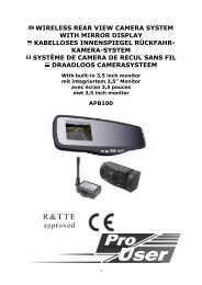
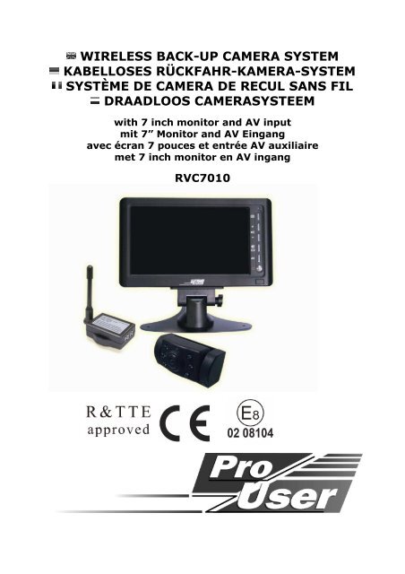
WIRELESS BACK-UP CAMERA SYSTEM<br />
KABELLOSES RÜCKFAHR-KAMERA-SYSTEM<br />
SYSTÈME <str<strong>on</strong>g>DE</str<strong>on</strong>g> CAMERA <str<strong>on</strong>g>DE</str<strong>on</strong>g> RECUL SANS FIL<br />
DRAADLOOS CAMERASYSTEEM<br />
with 7 inch m<strong>on</strong>itor and AV input<br />
mit 7” M<strong>on</strong>itor and AV Eingang<br />
avec écran 7 pouces et entrée AV auxiliaire<br />
met 7 inch m<strong>on</strong>itor en AV ingang<br />
<str<strong>on</strong>g>RVC7010</str<strong>on</strong>g>
INTRODUCTION<br />
The Pro-User <str<strong>on</strong>g>RVC7010</str<strong>on</strong>g> is member of the family of advanced car back-up systems<br />
manufactured by Pro User Internati<strong>on</strong>al Ltd.<br />
The Pro-User Wireless Back-up Camera and M<strong>on</strong>itor, when used as described, will<br />
improve your ability to see behind your car, camper, trailer, or mini-van. We have taken<br />
numerous measures in quality c<strong>on</strong>trol to ensure that your product arrives in top c<strong>on</strong>diti<strong>on</strong>,<br />
and will perform to your satisfacti<strong>on</strong>.<br />
Please carefully read and follow the following safety and operating instructi<strong>on</strong>s.<br />
IMPORTANT SAFETY INSTRUCTIONS<br />
Before You Install<br />
If you are not c<strong>on</strong>fident working with 12 volt DC vehicle wiring, removing and reinstalling<br />
interior panels, carpeting, dashboards or other comp<strong>on</strong>ents of your vehicle, c<strong>on</strong>tact the<br />
vehicle’s manufacturer, or c<strong>on</strong>sider having the camera system professi<strong>on</strong>ally installed.<br />
Interference<br />
This device, as well as all other wireless devices, may be subject to interference.<br />
Interference may be caused by cell ph<strong>on</strong>es, Bluetooth headsets, Wi-FI routers, power<br />
lines and other various electrical equipment, etc.<br />
Repair<br />
The camera system should not be opened. Any attempt at modificati<strong>on</strong> or repair by the<br />
user will entail the loss of your guarantee.<br />
PARTS<br />
1. M<strong>on</strong>itor 2. Camera with mounting plate<br />
3. Transmitter-box 4. Mounting accessories<br />
5. M<strong>on</strong>itor power cable 6. Transmitter-box power cable
7. Dashboard stand 8. Mounting straps<br />
9. AV cable<br />
INSTALL<strong>ATI</strong>ON<br />
These instructi<strong>on</strong>s do not apply to all vehicles. They are <strong>on</strong>ly meant as a general<br />
guide due to the number of different makes & models. For vehicle specific<br />
questi<strong>on</strong>s c<strong>on</strong>tact your vehicle’s manufacturer.<br />
Camera installati<strong>on</strong><br />
There are several ways to mount the camera <strong>on</strong> the back of your car. But the most<br />
c<strong>on</strong>venient is to mount it near the license plate of the car. Supplied is <strong>on</strong>e mounting plate<br />
that can be fixed behind the license plate. The camera is tiltable, camera angle can be<br />
adjusted manually <strong>on</strong> vertical directi<strong>on</strong>. Make sure that its field of view and detecti<strong>on</strong> are<br />
not obstructed.<br />
Er wordt een m<strong>on</strong>tageplaat meegeleverd, die achter de originele kentekenplaat wordt<br />
gem<strong>on</strong>teerd. De camera zelf is zwenkbaar; de camera-hoek kan met de hand in verticale<br />
richting worden aangepast. Zorg ervoor dat het gezichtsveld en de detectering niet wordt<br />
gehinderd door obstakels en dergelijke.<br />
At some type of cars it is not possible to mount the camera near the license plate. You<br />
may have to find another spot at the back of your car to mount the camera.
1. Remove the rear license plate, and then loosen the license plate bolts/screws.<br />
2. Positi<strong>on</strong> the supplied mounting plates(with camera together) behind the license plate<br />
bracket. Secure both license plate bracket and mounting plates with the license plate<br />
bracket bolts/screws.<br />
3. Mount the license plate <strong>on</strong> the license plate bracket.<br />
4. Choose a routing path for the camera’s power cable through the vehicle’s body to the<br />
reverse light circuit. If in doubt, seek professi<strong>on</strong>al installati<strong>on</strong> assistance.<br />
5. Some vehicles may have a hole available to pass the wire through, such as where the<br />
license plate light is mounted, or you can drill a hole close to where the power cable<br />
is attached to the camera. Once you have chosen where the cable will enter the<br />
vehicle’s body, remove the camera. If you are able to use an existing opening, skip<br />
the next two steps.<br />
6. Before you drill a hole you MUST CHECK and see WHAT IS BEHIND WHERE YOU ARE<br />
DRILLING. If there are any vehicle comp<strong>on</strong>ents, such as electrical parts or fuel<br />
system comp<strong>on</strong>ents behind where you are drilling, you must take whatever<br />
precauti<strong>on</strong> is necessary not to damage them. Remove the license plate and camera<br />
before drilling.<br />
7. After you have drilled the hole, insert the supplied grommet, then pass the camera<br />
cables through the grommet into the vehicle. You must use the grommet to prevent<br />
the metal edge of the hole from cutting the camera cable.<br />
8. Mount the transmitter box inside the trunk. C<strong>on</strong>nect the camera’s power cable and<br />
the transmitter box power cable to the transmitter box.<br />
9. Next you’ll need to find the vehicle’s reverse lights. Turn the vehicle’s igniti<strong>on</strong> key to<br />
the accessory positi<strong>on</strong>, engage the parking brake and put the car in reverse. Look at<br />
the vehicle’s tail lights to see where the reverse lights are located, they are the white<br />
lights. To locate the reverse light’s 12V+ wire it will be necessary to gain access to
the rear of the vehicle’s tail light. For help locating the vehicle’s reverse light circuit<br />
c<strong>on</strong>tact your vehicle’s manufacturer for vehicle specific wiring diagrams.<br />
10. Once you have located the reverse light circuit you will have to route the transmitter<br />
box power cable to that locati<strong>on</strong>. You must securely fasten the power cable to prevent<br />
it from being caught <strong>on</strong> any vehicle comp<strong>on</strong>ent such as the trunk hinge. Never route<br />
the cable <strong>on</strong> the outside of the vehicle!<br />
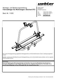
11. The reverse light sockets <strong>on</strong> most<br />
vehicles have two wires<br />
c<strong>on</strong>nected to them. Usually the<br />
negative wire is black and the<br />
positive wire is a colored wire. If<br />
you are uncertain about the<br />
wiring, you can use a 12 volt<br />
multimeter available at most auto<br />
parts stores to determine which<br />
is the positive wire. Follow the<br />
manufacturer’s instructi<strong>on</strong>s for<br />
the safe use of the multimeter.<br />
12. After determining which wire is<br />
the positive and which is the<br />
negative, turn off the igniti<strong>on</strong> key,<br />
then remove the battery’s negative cable.<br />
13. Splice the red wire using the supplied in-line wire c<strong>on</strong>nectors to the reverse light’s<br />
positive (+) wire. Use a set of slip joint pliers to squeeze the TAP and insure good<br />
c<strong>on</strong>necti<strong>on</strong>.<br />
14. Next splice the black wire of the transmitter box power cable to the reverse light’s<br />
negative (-) wire or ground.<br />
15. Replace the reverse light bulb, and then re-install the light socket. Secure all the<br />
wires with cable ties or electrical tape.<br />
16. Re-attach the negative battery cable to the battery.
M<strong>on</strong>itor Installati<strong>on</strong><br />
When choosing a locati<strong>on</strong> to mount the m<strong>on</strong>itor, make sure the m<strong>on</strong>itor is in an<br />
area that will not obstruct your visi<strong>on</strong> while driving.<br />
The <str<strong>on</strong>g>RVC7010</str<strong>on</strong>g> can be fixed in your vehicle <strong>on</strong> several ways. Placed <strong>on</strong> your dashboard via<br />
the dashboard stand or fixed via the supplied straps <strong>on</strong> you visor or a headrest.<br />
A. Dashboard stand<br />
1. Before mounting the m<strong>on</strong>itor, clean the dashboard surface well.<br />
2. Positi<strong>on</strong> the stand to the dashboard surface which suits your requirement.<br />
3. Stick the double-side tape foam at the bottom of the stand.<br />
4. Press the stand against the dashboard surface to fix the locati<strong>on</strong>.<br />
5. Snap in the m<strong>on</strong>itor to the stand mounting arm.<br />
6. Adjust the mounting arms to suit your view angle to the m<strong>on</strong>itor.<br />
7. To remove the m<strong>on</strong>itor from the stand mounting arm, press the<br />
arrow sign <strong>on</strong> the stand mounting arm to release.<br />
B. Visor and Headrest Mount<br />
1. Use the supplied two straps to pass through the recesses at the back of the m<strong>on</strong>itor<br />
unit.<br />
2. Locate the m<strong>on</strong>itor <strong>on</strong> the visor or headrest.<br />
3. Pass the straps across the visor or headrest.<br />
4. Tighten the straps to fix the locati<strong>on</strong>.<br />
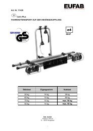
M<strong>on</strong>itor 12V c<strong>on</strong>necti<strong>on</strong><br />
1. Route the power cable to the vehicle’s cigarette lighter<br />
socket/12V power outlet. The cable must not interfere with<br />
the safe operati<strong>on</strong> of the vehicle.<br />
2. Insert the small 12 Volt DC plug of the power cable into the<br />
right side of the m<strong>on</strong>itor.<br />
3. Plug the 12 Volt cigarette lighter plug into the vehicle’s<br />
cigarette lighter socket.<br />
To maximize the effectiveness of the sucti<strong>on</strong> mount, it is recommended that the<br />
applicati<strong>on</strong> be performed under the following c<strong>on</strong>diti<strong>on</strong>s:<br />
• Surface temperature should be between 21 and 38 degrees Celsius.<br />
• Applicati<strong>on</strong> below 10 degrees should be avoided.<br />
• Applicati<strong>on</strong> should not occur in direct sunlight.<br />
NOTE: UN<str<strong>on</strong>g>DE</str<strong>on</strong>g>R EXTREME BRIGHT LIGHT CONDITIONS, THE SCRE<str<strong>on</strong>g>EN</str<strong>on</strong>g> IMAGE MAY TAKE A<br />
FEW SECONDS TO STABLIZE. PLEASE WAIT UNTIL THE IMAGE HAS STABLIZED BEFORE<br />
BACKING UP.<br />
System testing<br />
1. Make sure that both vehicles’ battery cables are c<strong>on</strong>nected to the battery of the car.<br />
2. Turn the igniti<strong>on</strong> key to the accessory positi<strong>on</strong>, do not start the vehicle.<br />
3. Engage the parking brake, and then put the shifter in the reverse positi<strong>on</strong>.
4. Look at the m<strong>on</strong>itor, if the image does not match your rear view mirror press the<br />
Image Orientati<strong>on</strong> butt<strong>on</strong> <strong>on</strong> the m<strong>on</strong>itor to correct the image.<br />
After testing the unit and you are satisfied with the route you have chosen for the<br />
cabling, you must permanently install it.<br />
Route all wires behind interior panels or under carpeting so they are hidden. Use<br />
supplied cable ties to neatly gather any excess wire.<br />
OPER<strong>ATI</strong>ON<br />
The m<strong>on</strong>itor will automatically turn <strong>on</strong> when the vehicle is in reverse gear.<br />
There are 6 c<strong>on</strong>trol butt<strong>on</strong>s available for users to have their c<strong>on</strong>trols:<br />
M<str<strong>on</strong>g>EN</str<strong>on</strong>g>U<br />
AUDIO + / +<br />
AUDIO - / -<br />
AUDIO MUTE / GUI<str<strong>on</strong>g>DE</str<strong>on</strong>g>LINE<br />
AV INPUT<br />
POWER<br />
POWER butt<strong>on</strong><br />
Press the POWER butt<strong>on</strong> to supply power to the m<strong>on</strong>itor. When the m<strong>on</strong>itor image is <strong>on</strong>,<br />
the blue LED will be lit. If there is power to the m<strong>on</strong>itor, but the m<strong>on</strong>itor image is off, the<br />
blue LED will blink <strong>on</strong> and off. When the m<strong>on</strong>itor power is off, no picture can appear <strong>on</strong><br />
the screen and the blue LED will be off.<br />
M<str<strong>on</strong>g>EN</str<strong>on</strong>g>U butt<strong>on</strong><br />
Press the M<str<strong>on</strong>g>EN</str<strong>on</strong>g>U butt<strong>on</strong> to enter the menu screen as shown below:<br />
Repeat pressing the M<str<strong>on</strong>g>EN</str<strong>on</strong>g>U butt<strong>on</strong> to select Brightness,<br />
c<strong>on</strong>trast, colour or directi<strong>on</strong> of the picture.<br />
Press the + butt<strong>on</strong> or – butt<strong>on</strong> to adjust settings within the<br />
c<strong>on</strong>trol selected. Press the + butt<strong>on</strong> to increase the value<br />
and press the – butt<strong>on</strong> to decrease the value.<br />
To exit the menu screen, select exit <strong>on</strong> the screen.
Screen orientati<strong>on</strong><br />
To change the orientati<strong>on</strong> of the screen image, press the menu butt<strong>on</strong> until directi<strong>on</strong> is<br />
selected. By pressing the + or - butt<strong>on</strong> repeatedly, different screen orientati<strong>on</strong>s will be<br />
available. These different views allow you to<br />
mount the camera and m<strong>on</strong>itor in any<br />
positi<strong>on</strong> with keeping the right picture <strong>on</strong> the<br />
m<strong>on</strong>itor.<br />
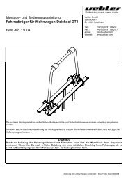
GUI<str<strong>on</strong>g>DE</str<strong>on</strong>g>LINE butt<strong>on</strong><br />
This camera system has the opti<strong>on</strong> to show distanceguidelines<br />
<strong>on</strong> the display. This helps you to visually<br />
see the distance between the objects behind your car.<br />
By pressing the guideline butt<strong>on</strong>, you can switch this<br />
opti<strong>on</strong> <strong>on</strong> and off.<br />
AV butt<strong>on</strong><br />
With the AV butt<strong>on</strong> the AV-input can be selected (<str<strong>on</strong>g>Manual</str<strong>on</strong>g> mode).<br />
To enable or disable the automatically switching from AV input to Back up Camera view,<br />
press M<str<strong>on</strong>g>EN</str<strong>on</strong>g>U butt<strong>on</strong> until BACK UP is selected. Then press + or - repeatedly, to switch it<br />
to AUTO or MANUAL mode. When it is under AUTO mode, the screen will automatically<br />
switch from Audio/Video Input view to Back up Camera View, while under MANUAL mode,<br />
you have to press the AV key to manually switch to Back up Camera view or to switch to<br />
Audio/Video device.<br />
AV Input<br />
Use the supplied AV Cable to c<strong>on</strong>nect between the m<strong>on</strong>itor and external audio/video<br />
devices.<br />
1. Insert the small ph<strong>on</strong>e jack into the right side of the m<strong>on</strong>itor.<br />
2. Plug the yellow colour jack to the video output and white<br />
colour jack to the audio output <strong>on</strong> the external audio/video<br />
device. Make sure your audio/video device is <strong>on</strong>.<br />
3. Press the AV butt<strong>on</strong> to switch to the external audio/video<br />
mode.
TECHNICAL SPECIFIC<strong>ATI</strong>ONS<br />
Camera<br />
Operating Voltage 12V DC<br />
Current c<strong>on</strong>sumpti<strong>on</strong> 350<br />
Optical lens 2,4mm / F2,1<br />
Camera view angle 110 degree<br />
Wireless transmitter<br />
Transmissi<strong>on</strong> frequency 2414MHz<br />
RF transmissi<strong>on</strong> distance (open space) >60M<br />
LCD m<strong>on</strong>itor<br />
Operati<strong>on</strong> Voltage 12V DC<br />
Standby Current
EI<str<strong>on</strong>g>NL</str<strong>on</strong>g>EITUNG<br />
Der Artikel Pro-User <str<strong>on</strong>g>RVC7010</str<strong>on</strong>g> gehört zur Familie der zukunftsweisenden Auto-Rückfahr-<br />
Kamera-Systeme der Firma Pro-User-Internati<strong>on</strong>al Ltd.<br />
Die kabellose Pro User Rückfahr-Kamera mit M<strong>on</strong>itor ermöglicht es Ihnen bei<br />
ordnungsgemäßer Bedienung, hinter Ihr Auto, Ihren Anhänger oder Mini-Van zu sehen.<br />
Es wurden zahlreiche Maßnahmen bei der Qualitätsk<strong>on</strong>trolle ergriffen, um Ihnen ein Top<br />
Produkt zu Ihrer Zufriedenheit zu liefern.<br />
Bitte lesen Sie die Bedienungsanleitung sorgfältig durch und folgen Sie den<br />
Sicherheitshinweisen und der M<strong>on</strong>tageanleitung.<br />
WICHTIGE SICHERHEITSHINWEISE<br />
Vor der M<strong>on</strong>tage<br />
Falls Sie sich nicht sicher fühlen, dieses System an die 12V Stromversorgung Ihres<br />
Fahrzeuges selbstständig zu m<strong>on</strong>tieren (bohren v<strong>on</strong> Löchern, abnehmen v<strong>on</strong><br />
Verkleidungen etc.) nehmen Sie K<strong>on</strong>takt zu Ihrem Autohaus oder zur Kfz-Werkstatt Ihres<br />
Vertrauens auf. Dort können Sie eine professi<strong>on</strong>elle M<strong>on</strong>tage des Systems in Auftrag<br />
geben.<br />
Störung<br />
Dieses Kamera-System kann, genau wie andere kabellosen Systeme, bestimmten<br />
Störungen unterliegen. Störungen können verursacht werden durch Handys, Bluetooth,<br />
Headsets, Navigati<strong>on</strong>ssysteme und anderen elektrischen Geräten.<br />
Reparatur<br />
Dieses Kamera-System darf nicht geöffnet werden! Bei jeglichem Versuch einer<br />
Reparatur erlischt die Garantie.<br />
ZUBEHÖR<br />
1. M<strong>on</strong>itor 2. Kamera mit Befestigungsplatte<br />
3. Sender 4. Befestigungs-Material<br />
5. Kabel für M<strong>on</strong>itor 6. Kabel für Sender
7. Befestigung fürs 8. Befestigungs-Gurte<br />
Armaturenbrett<br />
9. AV Kabel<br />
MONTAGE<br />
Diese Bedienungsanleitung ist nicht für alle Fahrzeuge anzuwenden. Sie ist ein<br />
genereller Leitfaden für die meisten Fahrzeuge. Bei fahrzeugspezifischen Fragen<br />
wenden Sie sich bitte an Ihren Fahrzeughersteller.<br />
M<strong>on</strong>tage der Kamera<br />
Es gibt verschiedene Möglichkeiten, die Kamera an der Rückseite Ihres Fahrzeuges zu<br />
befestigen. die Gebräuchlichste ist, die Kamera nahe dem Nummernschild zu befestigen.<br />
Sie können hierbei die mitgelieferte M<strong>on</strong>tageplatte hinter dem Nummernschild befestigen<br />
und darauf die Kamera m<strong>on</strong>tieren. Die Kamera ist vertikal schwenkbar. Stellen Sie diese<br />
je nach Wunsch ein und achten Sie darauf dass das Sichtfeld der Kamera nicht<br />
beeinträchtigt wird.<br />
Bei manchen Fahrzeugen ist es leider nicht möglich, die Kamera nahe dem<br />
Nummernschild zu befestigen. Suchen Sie sich eine andere Stelle am Heck Ihres Autos.
1. Nehmen Sie das Nummernschild ab und drehen Sie die Schrauben des<br />
Nummernschildhalters heraus. Nehmen Sie den Halter ab.<br />
2. Positi<strong>on</strong>ieren Sie die Befestigungsplatten mitsamt Kamera hinter dem<br />
Nummernschildhalter und befestigen Sie die Befestigungsplatten und den<br />
Nummernschildhalter wieder am Fahrzeug.<br />
3. Befestigen Sie die Kamera mit die mitgelieferten Schrauben und Muttern an den<br />
Befestigungsplatten. Richten Sie die Kamera aus und ziehen Sie die Schrauben an.<br />
4. Wählen Sie jetzt eine Stelle, wo Sie das Elektrokabel der Kamera durch die Karosserie<br />
Ihres Autos zum Stromkabel des Rückfahrlichtes ziehen können.<br />
5. Einige Autos haben in der Nähe des Kennzeichens eine Bohrung, wo Sie das Kabel<br />
durchziehen können. Falls das nicht der Fall ist, müssen Sie in der Nähe des<br />
Kennzeichens, dicht an der Stelle, wo sich das Kabel der Kamera befindet, selber ein<br />
Loch bohren. Wenn Sie den Platz für das Bohrloch festgelegt haben können Sie die<br />
Kamera und das Kennzeichen wieder dem<strong>on</strong>tieren. Wenn Sie eine vorhandene<br />
Öffnung benutzen, können Sie die zwei folgenden Schritte überspringen.<br />
6. Bevor Sie bohren, dem<strong>on</strong>tieren Sie die Kamera und das Nummernschild. PRÜF<str<strong>on</strong>g>EN</str<strong>on</strong>g> SIE,<br />
BEVOR SIE BOHR<str<strong>on</strong>g>EN</str<strong>on</strong>g>, WAS SICH AUF <str<strong>on</strong>g>DE</str<strong>on</strong>g>R RÜCKSEITE <str<strong>on</strong>g>DE</str<strong>on</strong>g>R STELLE BEFIN<str<strong>on</strong>g>DE</str<strong>on</strong>g>T, WO<br />
SIE BOHR<str<strong>on</strong>g>EN</str<strong>on</strong>g> WOLL<str<strong>on</strong>g>EN</str<strong>on</strong>g>! Sorgen Sie z.B. dafür, dass sich dort keine Elektrokabel,<br />
Flüssigkeitstanks oder Leitungen befinden. Beachten Sie alle Vorsichtsmaßnahmen!<br />
7. Nachdem Sie gebohrt haben, befestigen Sie den mitgelieferten Kantenschutz in der<br />
Bohrung, um das Kabel vor den scharfen Rändern des Bohrloches zu schützen. Dann<br />
ziehen Sie das Kabel der Kamera ins Fahrzeuginnere.<br />
8. Befestigen Sie den Sender im Kofferraum. Verbinden Sie das Kabel der Kamera und<br />
das Kabel des Senders mit dem Sender.<br />
9. Schalten Sie die Zündung Ihres Auto an (nicht starten!), ziehen Sie die Handbremse<br />
an und legen Sie den Rückwärtsgang ein. Dann schauen Sie am Heck Ihres Autos, wo<br />
sich der Rückfahrscheinwerfer befindet. Um die Kabel vom Rückfahrscheinwerfer zu<br />
finden, müssen Sie die Rückseite der Heckbeleuchtung öffnen und die<br />
entsprechenden Kabel orten. Ggf. suchen Sie hierzu Ihr Autohaus oder die Kfz-<br />
Werkstatt Ihres Vertrauens auf.
10. Wenn Sie die entsprechenden Kabel gefunden haben, legen Sie das Kabel des<br />
Senders an den Verbindungspunkt. Sorgen Sie bitte dafür, das die Befestigung des<br />
Kabels sicher und fest ist, damit es beim Öffnen und Schließen der Heckklappe nicht<br />
beschädigt werden kann. Verlegen Sie das Kabel niemals außerhalb des Autos!<br />
11. An der K<strong>on</strong>taktdose des<br />
Rückfahrscheinwerfers sind zwei Drähte<br />
befestigt. Meistens ist der negative Draht<br />
schwarz und der positive farbig. Wenn Sie<br />
unsicher sind, können Sie mit einem 12 V<br />
Multimeter (im Fachhandel erhältlich) prüfen,<br />
welcher Draht positiv bzw. negativ ist. Folgen<br />
Sie der Bedienungsanleitung des Multimeters<br />
für den sicheren Gebrauch.<br />
12. Wenn Sie festgestellt haben, welcher Draht<br />
positiv bzw. negativ ist, schalten Sie die<br />
Zündung aus und entfernen Sie das negative<br />
Kabel Ihrer Autobatterie. So ist sichergestellt,<br />
das kein Strom auf den Drähten ist.<br />
13. Verbinden Sie den roten Draht vom Kabel des Senders mit dem positive Draht des<br />
Rückfahrscheinwerfers. Benutzen Sie dazu die beiliegenden Kabelklemmen. Drücken<br />
Sie die Klemmen fest mit einer Zange zusammen und clipsen Sie die rote<br />
Plastikabdeckung über diese K<strong>on</strong>taktstellen.<br />
14. Verbinden Sie nun den schwarzen Draht des Sender-Kabels mit dem negative Draht<br />
des Rückfahrscheinwerfers. (Benutzen Sie auch hier die Kabelklemmen)<br />
15. Verschließen Sie die Heckleuchte wieder (achten Sie darauf, dass die Glühlampe<br />
eingesetzt ist). Benutzen Sie Kabelbinder und spezielle Tapes (für<br />
Kabelverbindungen), damit alle Drähte und Kabel sicher und fest verlegt sind!<br />
16. Schließen Sie das negative Kabel Ihrer Autobatterie wieder an.
M<strong>on</strong>tage des M<strong>on</strong>itors<br />
Wenn Sie den passenden Platz zur Befestigung des M<strong>on</strong>itors gefunden haben,<br />
vergewissern Sie sich, das Sie während der Fahrt stets freie Sicht haben.<br />
Die <str<strong>on</strong>g>RVC7010</str<strong>on</strong>g> kann auf verschiedene Arten befestigt werden. Mit selbstklebendem<br />
Ständer auf dem Armaturenbrett oder mit den mitgelieferten Gurten an der<br />
S<strong>on</strong>nenblende des Beifahrersitzes oder an einer der hinteren Kopfstützen.<br />
A. Befestigung auf dem Armaturenbrett<br />
1. Vor der Befestigung reinigen Sie gut die Oberfläche des Armaturenbrettes.<br />
2. Positi<strong>on</strong>ieren Sie den Ständer auf der ausgewählten Stelle.<br />
3. Kleben Sie das doppelseitig klebende Schaumstoffpad auf die Unterseite<br />
des Ständers<br />
4. Pressen Sie den Ständer auf das Armaturenbrett.<br />
5. Befestigen Sie den M<strong>on</strong>itor in dem Befestigungsarm des Ständers.<br />
6. Richten Sie den M<strong>on</strong>itor so aus, das Sie den richtigen Blickwinkel<br />
haben.<br />
7. Um den M<strong>on</strong>itor wieder vom Ständer zu entfernen, drücken Sie bitte auf<br />
den Pfeil an der Rückseite des Trägerarms<br />
B. Befestigung an der S<strong>on</strong>nenblende oder Kopfstütze<br />
1. Ziehen Sie die mitgelieferten Straps durch die Vertiefungen auf der Rückseite des<br />
M<strong>on</strong>itors<br />
2. Justieren Sie den M<strong>on</strong>itor an der S<strong>on</strong>nenblende oder Kopfstütze<br />
3. Legen Sie die Gurte um die S<strong>on</strong>nenblende oder Kopfstütze<br />
4. Ziehen Sie die Gurte an, um die sichere Befestigung zu gewährleisten.<br />
M<strong>on</strong>itor 12V Verbindung<br />
1. Leiten Sie das M<strong>on</strong>itor-Kabel zum Zigarettenanzünder. Das<br />
Kabel so verlegen, das es Sie nicht bei der Fahrt gefährdet!<br />
2. Stecken Sie den kleinen 12V Stecker in die rechte Seite des<br />
M<strong>on</strong>itors.<br />
3. Stecken Sie den 12V Stecker in den Zigarettenanzünder<br />
ACHTUNG: BEI EXTREM HELL<str<strong>on</strong>g>EN</str<strong>on</strong>g> LICHTVERHÄLTNISS<str<strong>on</strong>g>EN</str<strong>on</strong>g> B<str<strong>on</strong>g>EN</str<strong>on</strong>g>ÖTIGT <str<strong>on</strong>g>DE</str<strong>on</strong>g>R<br />
MONITOR EINIGE SEKUND<str<strong>on</strong>g>EN</str<strong>on</strong>g> UM SICH DIES<str<strong>on</strong>g>EN</str<strong>on</strong>g> LICHTVERHÄLTNISS<str<strong>on</strong>g>EN</str<strong>on</strong>g><br />
ANZUPASS<str<strong>on</strong>g>EN</str<strong>on</strong>g>. WART<str<strong>on</strong>g>EN</str<strong>on</strong>g> SIE BITTE MIT <str<strong>on</strong>g>DE</str<strong>on</strong>g>M RÜCKWÄRTS FAHR<str<strong>on</strong>g>EN</str<strong>on</strong>g> BIS SICH DAS<br />
BILD STABILISIERT HAT.<br />
System Test<br />
1. Prüfen Sie, ob Sie das negative Kabel der Autobatterie wieder angeschlossen haben.<br />
2. Schalten Sie die Zündung Ihres Autos ein (nicht starten!)<br />
3. Ziehen Sie die Handbremse an und legen Sie den Rückwärtsgang ein.<br />
4. Schauen Sie auf den M<strong>on</strong>itor. Wenn dieses Bild nicht identisch ist mit dem Bild, was<br />
Sie im Rückspiegel sehen, drücken Sie den Bild-Orientierungs Knopf am M<strong>on</strong>itor um<br />
das Bild zu korrigieren.
5. Nachdem Sie den Test zu Ihrer Zufriedenheit beendet haben verlegen Sie alle noch<br />
frei liegenden Kabel.<br />
6. Verlegen Sie nun alle Kabel hinter den Fahrzeugverkleidungen oder unter den<br />
Fahrzeugteppichen, so dass sie nicht mehr sichtbar sind.<br />
Wenn Sie mit der Verkabelung zufrieden sind, befestigen bzw. verstauen Sie Kabel<br />
sorgfältig hinter der Innverkleidung, unter dem Innenteppich oder ähnlichem.<br />
BEDI<str<strong>on</strong>g>EN</str<strong>on</strong>g>UNG<br />
Der M<strong>on</strong>itor schaltet sich automatisch an, wenn der Rückwärtsgang eingelegt wird.<br />
Am M<strong>on</strong>itor finden Sie 6 K<strong>on</strong>trollschalter zur Benutzung:<br />
M<str<strong>on</strong>g>EN</str<strong>on</strong>g>U<br />
AUDIO + / +<br />
AUDIO - / -<br />
AUDIO STILL / ABSTAND<br />
AV EINGANG<br />
POWER<br />
POWER Schalter<br />
Drücken Sie den „Power“ Schalter um den M<strong>on</strong>itor mit Strom zu versorgen. Wenn das<br />
Bild da ist, leuchtet die blaue LED auf. Wenn der M<strong>on</strong>itor Strom hat, aber das Bild<br />
ausgestellt ist, blinkt die blaue LED.<br />
M<str<strong>on</strong>g>EN</str<strong>on</strong>g>U Schalter<br />
Wenn Sie den „Menu“ Schalter drücken erscheint auf dem M<strong>on</strong>itor wie folgt:<br />
Drücken Sie wiederholt den “Menu” Schalter um Helligkeit<br />
(Brightness), K<strong>on</strong>trast (C<strong>on</strong>trast), Farbe (Color) oder<br />
Ausrichtung (Directi<strong>on</strong>) des Bildes einzustellen.<br />
Mit “+” erhöhen Sie die Einstellungen, mit “-“ verringern Sie<br />
die Einstellungen.<br />
Um das Menu zu verlassen wählen sie “Exit” auf dem<br />
Bildschirm.
Bildschirm Anzeige<br />
Um die Anzeige des Bildschirms zu wechseln drücken Sie den Schalter „Menu“ solange,<br />
bis die Anzeige „Directi<strong>on</strong>“ erscheint. Durch drücken v<strong>on</strong> + oder – sind verschiedene<br />
Anzeigen möglich. Diese verschiedenen<br />
Ansichten ermöglichen es Ihnen bei jeglicher<br />
Anbringung der Kamera und des M<strong>on</strong>itors<br />
stets das richtige Bild auf dem M<strong>on</strong>itor zu<br />
sehen.<br />
ABSTANDS Schalter (Guideline)<br />
Dieses Kamera System kann Ihnen den ca. Abstand<br />
zum Hindernis visuell durch Balken anzeigen. Durch<br />
Drücken des Schalters können Sie diese Opti<strong>on</strong> an-<br />
oder ausschalten.<br />
AV Schalter<br />
Mit dem AV Schalter kann der AV Eingang gewählt werden.<br />
Drücken Sie den “Menu” Schalter, bis “BACK UP” auf dem M<strong>on</strong>itor erscheint. Hier können<br />
Sie durch drücken v<strong>on</strong> „+“ oder „-„ AUTO oder MANUAL auswählen. Wenn Sie AUTO<br />
wählen, wird die Rückfahrkamera automatisch aktiviert. Wenn Sie MANUAL wählen,<br />
können Sie über den „AV“ Schalter auswählen, ob Sie das Bild der Rückfahrkamera<br />
sehen wollen oder Audio/Video<br />
AV Eingang<br />
Wenn Sie z.B. DVD´s sehen wollen, verbinden Sie den M<strong>on</strong>itor und den DVD Player mit<br />
dem mitgelieferten AV-Kabel.<br />
1. Stecken Sie den schwarzen Stecker in die rechte Seite des<br />
M<strong>on</strong>itors.<br />
2. Stecken Sie den gelben Stecker in die Video Buchse und den<br />
weißen Stecker in die Audio Buchse Ihres DVD Players.<br />
Stellen Sie sicher, das Ihr DVD Player eingeschaltet ist.<br />
3. Drücken Sie den AV Schalter um zum externen Audio/Video<br />
Modus zu wechseln.<br />
LT. STVZO IST ES <str<strong>on</strong>g>DE</str<strong>on</strong>g>M FAHRER NICHT GESTATTET SICH WÄHR<str<strong>on</strong>g>EN</str<strong>on</strong>g>D <str<strong>on</strong>g>DE</str<strong>on</strong>g>R FAHRT<br />
DVD´S O<str<strong>on</strong>g>DE</str<strong>on</strong>g>R VI<str<strong>on</strong>g>DE</str<strong>on</strong>g>OS ANZUSEH<str<strong>on</strong>g>EN</str<strong>on</strong>g>!
TECHNISCHE SPEZIFIK<strong>ATI</strong>ON<br />
Kamera<br />
Betriebsspannung 12V DC<br />
Stromverbrauch 350<br />
Optische Linse 2,4mm / F2,1<br />
Sichtwinkel der Kamera 110 Grad<br />
Kabelloser Sender<br />
Übertragungfrequenz 2414MHz<br />
Übertragungsdistanz (ohne Hindernisse) >60M<br />
LCD M<strong>on</strong>itor<br />
Betriebsspannung 12V DC<br />
Standby Verbrauch
INTRODUCTION<br />
Le Pro-User <str<strong>on</strong>g>RVC7010</str<strong>on</strong>g> fait partie de la gamme de cameras de recules sans fils de<br />
dernières générati<strong>on</strong> fabriqués par Pro User Internati<strong>on</strong>al Ltd.<br />
Félicitati<strong>on</strong>s! Le système Pro-User améliorera c<strong>on</strong>sidérablement votre vue vers l'arrière<br />
de votre voiture, camping-car, caravane ou remorque, si vous l'utilisez comme décrit cidessous.<br />
Nous av<strong>on</strong>s testé sérieusement ce système pour être sûr que vous pourrez vous<br />
en servir sans problèmes et que vous serez entièrement satisfait de s<strong>on</strong> f<strong>on</strong>cti<strong>on</strong>nement.<br />
S’il vous plait, veuillez lire attentivement cette notice et suivre les instructi<strong>on</strong>s.<br />
IMPORTANT - CONSIGNES <str<strong>on</strong>g>DE</str<strong>on</strong>g> SECURITE<br />
Avant l’installati<strong>on</strong><br />
Si vous ne vous sentez pas capable d’intervenir sur le circuit électrique 12 volt DC d'une<br />
voiture, de dém<strong>on</strong>ter et rem<strong>on</strong>ter les panneaux intérieurs, la moquette, le tableau de<br />
bord ou d'autres pièces de votre voiture, <strong>on</strong> vous c<strong>on</strong>seille de prendre c<strong>on</strong>tact avec votre<br />
c<strong>on</strong>cessi<strong>on</strong>naire, votre garage ou centre auto pour faire installer ce système de faç<strong>on</strong><br />
professi<strong>on</strong>nelle par une pers<strong>on</strong>ne qualifié.<br />
Interférence<br />
Comme tous les systèmes sans fil, le Pro-User pourra être troublé dans s<strong>on</strong><br />
f<strong>on</strong>cti<strong>on</strong>nement par des portables, des casques Bluetooth, des systèmes GPS, des câbles<br />
électrique, ou par d'autres appareils électriques.<br />
Réparati<strong>on</strong><br />
La camera et le m<strong>on</strong>iteur ne doivent jamais êtres ouvert. Autrement l’utilisateur perd la<br />
garantie.<br />
CONT<str<strong>on</strong>g>EN</str<strong>on</strong>g>U<br />
1. M<strong>on</strong>itor / Récepteur 2. Camera avec plaque de m<strong>on</strong>tage<br />
3. Boîtier transmetteur 4. Accessoires de fixati<strong>on</strong><br />
5. Câble d’alimentati<strong>on</strong> 6. Câble d’alimentati<strong>on</strong><br />
pour le m<strong>on</strong>iteur pour le boîtier transmetteur
7. Pied pour tableau de bord 8. Sangles de fixati<strong>on</strong><br />
9. Câble AV<br />
INSTALL<strong>ATI</strong>ON<br />
C’est instructi<strong>on</strong>s d’installati<strong>on</strong> ne s’appliquent pas à tous les véhicules mais à<br />
la majorité. Sur certains véhicules il n’est pas possible de fixer la caméra sur la<br />
plaque d’immatriculati<strong>on</strong>. Dans ce cas c<strong>on</strong>tacter votre c<strong>on</strong>cessi<strong>on</strong>naire ou votre<br />
garagiste afin de trouver un autre endroit approprié.<br />
Camera installati<strong>on</strong><br />
Il y’a différentes manières de fixer la camera de recule. La plus pratique étant à<br />
proximité de la plaque d’immatriculati<strong>on</strong> du véhicule. Une plaque de m<strong>on</strong>tage qui peut<br />
être fixé derrière la plaque d’immatriculati<strong>on</strong> est fournie, la plaque de m<strong>on</strong>tage est reliée<br />
à la caméra. La caméra est inclinable, l’angle de la caméra peut être ajusté<br />
manuellement à la verticale. Assurez-vous que le champ de visi<strong>on</strong> et de détecti<strong>on</strong> n’est<br />
pas obstrué.<br />
Sur certains véhicules il n’est pas possible de fixer la camera à l’aide des plaques de<br />
m<strong>on</strong>tages fournies. Alors il vous faut trouver un autre endroit à l’arrière du véhicule pour<br />
fixer la caméra.
1. Enlevez la plaque d’immatriculati<strong>on</strong> en la dévissant ou en enlevant les rivets (Pour<br />
enlever les rivets utiliser une perceuse avec une mèche adaptée ou aller chez votre<br />
garagiste, vendeur de plaque d’immatriculati<strong>on</strong>, etc...)<br />
2. Placez les plaques de m<strong>on</strong>tages (avec la caméra) derrières la plaque<br />
d’immatriculati<strong>on</strong> puis fixez les solidairement avec la plaque d’immatriculati<strong>on</strong>. Par vis<br />
ou rivets.<br />
3. Fixer la plaque d’immatriculati<strong>on</strong> sur le support de plaque.<br />
4. Choisissez un chemin d’accès pour le câble d’alimentati<strong>on</strong> de la camera dans<br />
l’intérieure du coffre de votre véhicule afin de le brancher sur le faisceau électrique de<br />
l’ampoule de marche arrière. Si vous avez des doutes, c<strong>on</strong>sultez un professi<strong>on</strong>nel.<br />
Votre garagiste, centre auto ou c<strong>on</strong>cessi<strong>on</strong>naire.<br />
5. Certains véhicules <strong>on</strong>t d’origine un trou à cet effet, qui vous permet de faire passer le<br />
câble d’alimentati<strong>on</strong>. Dans le cas c<strong>on</strong>traire il vous faut percer un trou. De préférence<br />
derrière la plaque d’immatriculati<strong>on</strong>. Une fois que vous avez identifié l’endroit retirez<br />
la camera. Si vous avez la possibilité d’utiliser un trou de passage existant alors vous<br />
pouvez sauter le 2 points suivants.<br />
6. Avant de PERCER un TROU, vous devez VERIFIER CE QU’IL Y’A <str<strong>on</strong>g>DE</str<strong>on</strong>g>RRIERE, à<br />
l’intérieur de votre véhicule. Si il y’à des câbles, composant ou autre objet, alors vous<br />
devez choisir un autre endroit pour percer le trou. Enlever la plaque et la caméra<br />
avant de percer.<br />
7. Après avoir percer le trou, veuillez insérer la bague de passage fournie. Elle protège<br />
votre câble d’alimentati<strong>on</strong> c<strong>on</strong>tre les bords tranchants.<br />
8. Maintenant fixez le boîtier transmetteur dans votre coffre. Raccordez le câble<br />
d’alimentati<strong>on</strong> à votre caméra puis au boîtier de transmissi<strong>on</strong>.<br />
9. En suite vous devez identifier l’ampoule de marche arrière (généralement le feu<br />
blanc). Tournez la clef de c<strong>on</strong>tact de votre véhicule, serrez le frein à main puis<br />
enclencher la marche arrière. Regardez à l’arrière de votre véhicule ou demander à
une autre pers<strong>on</strong>ne de regardez quelle ampoule s’allume. Trouvez le câble qui<br />
alimente l’ampoule de marche arrière. Pour se faire vous devez retournez à l’arrière<br />
de votre véhicule. Si vous n’y parvenez pas alors c<strong>on</strong>sultez un professi<strong>on</strong>nel, votre<br />
garagiste ou c<strong>on</strong>cessi<strong>on</strong>naire.<br />
10. Une fois le circuit électrique le l’ampoule de marche arrière identifié, vous devez<br />
passer le câble d’alimentati<strong>on</strong> du boîtier transmetteur vers le câble électrique de<br />
l’ampoule. Fixez-le de manière très sûre. Le câble ne doit pas pouvoir être arraché<br />
par des objets transportés dans le coffre ultérieurement. Ne jamais faire passer le<br />
câble à l’extérieur du véhicule!<br />
11. La plus part des ampoules de<br />
marche arrière s<strong>on</strong>t alimenté par 2<br />
fils électriques. En général le noir<br />
est le négatif et le rouge le positif.<br />
Dans le doute c<strong>on</strong>trôlez avec un<br />
voltmètre 12V (disp<strong>on</strong>ible dans la<br />
majorité des magasins de bricolage)<br />
ou allez c<strong>on</strong>sulter un professi<strong>on</strong>nel.<br />
Suivez les instructi<strong>on</strong>s de la notice<br />
du voltmètre.<br />
12. Après avoir déterminé les polarités<br />
des fils électriques veuillez retirer la<br />
clef de c<strong>on</strong>tacte puis déc<strong>on</strong>nectez la<br />
cosse (-) négative de votre batterie<br />
de démarrage (la batterie se situe<br />
souvent dans le compartiment moteur du véhicule), ceci afin d’être sûr qu’il n’y ai<br />
plus de courant dans les circuits électrique. Pour trouver la batterie veuillez c<strong>on</strong>sulter<br />
la notice de votre véhicule.<br />
13. Fixez le fil rouge du câble de l’émetteur à l’aide du c<strong>on</strong>necteur rouge dans le câble<br />
positif (+) des feux de recule. Prenez une pince pour faire entrer la languette<br />
métallique et pliez/accrochez ensuite le couvercle rouge en plastique.<br />
14. Puis répétez l’opérati<strong>on</strong> (14) avec le câble négatif (-) (souvent noir).<br />
15. Replacez l’ampoule de marque arrière et le cache puis sécuriser les câbles de sorte<br />
qu’il de puisse pas être accrochés par un objet transporté dans le coffre. Pour<br />
sécuriser les câbles, veuillez utiliser des serre-fils ou du ruban adhésif pour<br />
installati<strong>on</strong>s électriques.<br />
16. Rec<strong>on</strong>necté la cosse négative à votre batterie.<br />
Installati<strong>on</strong> du m<strong>on</strong>iteur<br />
Pour choisir l’endroit d’installati<strong>on</strong> du m<strong>on</strong>iteur, veillez à ce qu’il ne puisse pas<br />
gêner la visibilité du c<strong>on</strong>ducteur.<br />
Le <str<strong>on</strong>g>RVC7010</str<strong>on</strong>g> peut être fixé de différentes manières dans votre véhicule. Placé sur tableau<br />
de bord grâce a la fixati<strong>on</strong> fournie ou a l’aide des sangles de fixati<strong>on</strong> sur le par soleil ou<br />
repose tête.
A. Sur le tableau de bord<br />
1. Avant d’installer le pied veuillez bien nettoyer l’endroit.<br />
2. Positi<strong>on</strong>nez le pied à l’endroit choisi.<br />
3. Enlever la protecti<strong>on</strong> de l’autocollant double face.<br />
4. Appuyez sur le pied (c<strong>on</strong>tre le tableau de bord) afin de le fixer.<br />
5. Enfichez le m<strong>on</strong>iteur sur le pied de fixati<strong>on</strong>.<br />
6. Ajustez le pied à votre angle de visi<strong>on</strong>.<br />
7. Pour retirer le m<strong>on</strong>iteur du pied de fixati<strong>on</strong> veuillez appuyer sur<br />
le signe en croix.<br />
B. Sur le par soleil ou repose tête<br />
1. Prenez les sangles de fixati<strong>on</strong> fournies et passez les dans les fentes à l’arrière du<br />
m<strong>on</strong>iteur.<br />
2. Placez le m<strong>on</strong>iteur sur le par soleil ou le repose tête.<br />
3. Passez les sangles derrière le par soleil ou repose tête<br />
4. Tendez les sangles afin de fixer le m<strong>on</strong>iteur.<br />
Alimentati<strong>on</strong> 12V du m<strong>on</strong>iteur<br />
1. Passez le câble d’alimentati<strong>on</strong> à partir de la prise allume<br />
cigares vers le m<strong>on</strong>iteur. Veillez à ce que le câble ne puisse<br />
pas gêner la c<strong>on</strong>duite du véhicule.<br />
2. Insérez la petite fiche 12V dans le côté droit du m<strong>on</strong>iteur.<br />
3. Insérez la grosse prise 12V dans la prise allume cigare de<br />
votre véhicule.<br />
Pour optimiser la fixati<strong>on</strong> du m<strong>on</strong>iteur sur le tableau de bord il est recommandé:<br />
• De l’installer lors de températures ambiantes de 21 à 38 C°.<br />
• De ne pas le coller lors de températures sous 10 C°.<br />
• Ne pas exposer la fixati<strong>on</strong> directement au soleil.<br />
• De bien dégraisser l’endroit de fixati<strong>on</strong>.<br />
REMARQUE: lors d’une lumière ambiante très Claire, le m<strong>on</strong>iteur nécessite un certain<br />
temps d’adaptati<strong>on</strong>.<br />
Pour tester le système<br />
1. Assurez-vous que la cosse négative est branchée sur la batterie du véhicule.<br />
2. Mettez le c<strong>on</strong>tact en tournant la clef, ne démarrez pas.<br />
3. Serrez le frein à main puis engagez la marche arrière.<br />
4. Regardez le m<strong>on</strong>iteur, si l’image ne corresp<strong>on</strong>d pas à celle que vous voyez dans le<br />
rétroviseur, veuillez appuyer sur la touché d’orientati<strong>on</strong> de l’image.<br />
5. Une fois le test effectué et si vous êtes satisfait du résultat, alors fixer définitivement<br />
les câbles d’alimentati<strong>on</strong> dans votre coffre.<br />
Lorsque vous avez testé l’unité et que vous êtes satisfait de l’emplacement choisi,<br />
vous devez l’installer de manière permanente. Placez les câbles derrière les caches et<br />
moquettes de votre véhicule. Utilisez les serres fils fournis pour fixer le surplus de<br />
câbles.
FONCTIONNEM<str<strong>on</strong>g>EN</str<strong>on</strong>g>T<br />
Le m<strong>on</strong>iteur s’allume automatiquement lors ce que vous engagez la marche arrière.<br />
Il y à 6 bout<strong>on</strong>s de c<strong>on</strong>trôle à votre dispositi<strong>on</strong>:<br />
M<str<strong>on</strong>g>EN</str<strong>on</strong>g>U<br />
AUDIO + / +<br />
AUDIO - / -<br />
AUDIO MUTE /<br />
Ligne graduée<br />
<str<strong>on</strong>g>EN</str<strong>on</strong>g>TRÉE AV AUX<br />
Marche/Arrêt<br />
Bout<strong>on</strong> POWER (M/A)<br />
Appuyez sur le bout<strong>on</strong> POWER pour allumer le m<strong>on</strong>iteur. Une LED s’éclaire quand l’image<br />
apparaît. Si le m<strong>on</strong>iteur est allumé mais sans image, alors la LED bleu clignote. Lorsque<br />
le m<strong>on</strong>iteur est éteint, pas d’image apparaît et la LED bleu ne s’allume pas.<br />
Bout<strong>on</strong> M<str<strong>on</strong>g>EN</str<strong>on</strong>g>U<br />
Appuyer sur le bout<strong>on</strong> M<str<strong>on</strong>g>EN</str<strong>on</strong>g>U pour entrer dans le menu comme dém<strong>on</strong>tré dans l’image cidessous:<br />
Appuyer de nouveau sur le bout<strong>on</strong> M<str<strong>on</strong>g>EN</str<strong>on</strong>g>U pour valider une<br />
sélecti<strong>on</strong> Brightness (luminosité), c<strong>on</strong>trast, colour ou<br />
directi<strong>on</strong> l’image.<br />
Appuyer sur + et – pour effectuer le réglage.<br />
Pour quitter le menu, sélecti<strong>on</strong>nez EXIT.<br />
Orientati<strong>on</strong> de l’image<br />
Pour changer l’orientati<strong>on</strong> de l’image appuyer sur menu lorsque directi<strong>on</strong> est sélecti<strong>on</strong>né.<br />
Ensuite faite varier l’orientati<strong>on</strong> en appuyant sur + et -.
Bout<strong>on</strong> GUI<str<strong>on</strong>g>DE</str<strong>on</strong>g>LINE (grille de graduati<strong>on</strong>)<br />
Cette camera de recule dispose d’un dispositif qui<br />
affiche une graduati<strong>on</strong> de distance sur le m<strong>on</strong>iteur.<br />
Ceci vous aide à évaluer la distance entre votre<br />
véhicule et l’obstacle derrière votre véhicule. En<br />
appuyant sur le bout<strong>on</strong> GUIDLINE vous activez et<br />
désactivez le dispositif.<br />
Bout<strong>on</strong> AV<br />
Grâce au bout<strong>on</strong> AV vous pouvez sélecti<strong>on</strong>ner une source AV auxiliaire (mode manuel).<br />
Pour activer ou désactiver la commutati<strong>on</strong> automatique, appuyez sur la touché M<str<strong>on</strong>g>EN</str<strong>on</strong>g>U<br />
pendant que la marche arrière est enclenchée puis appuyez sur + ou – pour activer ou<br />
désactiver le mode automatique.<br />
C<strong>on</strong>nexi<strong>on</strong> d’une source AV auxiliaire<br />
Utiliser le câble fourni pour raccorder une source auxiliaire (par ex. Lecteur DVD) au<br />
m<strong>on</strong>iteur.<br />
1. Insérez la petite prise (Jack) dans le côté droit du m<strong>on</strong>iteur.<br />
2. Insérez la fiche RCA jaune dans la sortie VI<str<strong>on</strong>g>DE</str<strong>on</strong>g>O de votre<br />
appareil et la RCA blanche dans la sortie AUDIO.<br />
Assurez-vous que votre source est allumée.<br />
3. Appuyer sur le bout<strong>on</strong> AV pour commuter en mode<br />
audio/vidéo auxiliaire.
CARACTERISTIQUES TECHNIQUES<br />
Caméra<br />
Alimentati<strong>on</strong> 12V DC<br />
C<strong>on</strong>sommati<strong>on</strong> 350<br />
Lentille 2,4mm / F2,1<br />
Angle de vue de la camera 110 degré<br />
Transmetteur sans fil<br />
Fréquence de transmissi<strong>on</strong> 2414MHz<br />
Porté (champ libre) >60M<br />
M<strong>on</strong>iteur LCD<br />
Alimentati<strong>on</strong> 12V DC<br />
C<strong>on</strong>sommati<strong>on</strong> en veille
I<str<strong>on</strong>g>NL</str<strong>on</strong>g>EIDING<br />
De Pro-User <str<strong>on</strong>g>RVC7010</str<strong>on</strong>g> maakt deel uit van de serie geavanceerde achteruitrijsystemen<br />
vervaardigd door Pro User Internati<strong>on</strong>al Ltd.<br />
De Pro-User draadloze achteruitrijcamera en m<strong>on</strong>itor, mits gebruikt zoals beschreven,<br />
zorgen ervoor dat u beter zicht hebt op alles achter uw auto, camper, aanhangwagen of<br />
bestelbus. We hebben vele maatregelen genomen tijdens kwaliteitsc<strong>on</strong>troles zodat het<br />
product u in topc<strong>on</strong>ditie bereikt en naar uw tevredenheid zal werken.<br />
Lees de volgende veiligheids- en bedieningsinstructies zorgvuldig door.<br />
BELANGRIJKE VEILIGHEIDS INSTRUCTIES<br />
Voordat u het systeem installeert<br />
Als u niet thuis bent in het werken met de 12-volt DC bedrading van uw voertuig, het<br />
dem<strong>on</strong>teren en opnieuw aanbrengen van de binnenpanelen, vloerbedekking of andere<br />
<strong>on</strong>derdelen van uw voertuig, neem dan c<strong>on</strong>tact op met de fabrikant van het voertuig of<br />
overweeg om het camerasysteem door vaklieden te laten instaleren.<br />
Storing<br />
Dit apparaat kan net zoals alle andere draadloze apparaten <strong>on</strong>derhevig zijn aan storingen.<br />
Dergelijke storingen kunnen worden veroorzaakt door mobiele telefo<strong>on</strong>s, Bluetooth<br />
headsets, Wi-Fi routers, elektriciteitsleidingen en andere elektrische apparaten, etc.<br />
Reparatie<br />
Het camerasysteem mag niet geopend worden. Elke poging tot wijziging of reparatie door<br />
de gebruiker heeft tot gevolg dat uw garantie vervalt.<br />
ON<str<strong>on</strong>g>DE</str<strong>on</strong>g>R<str<strong>on</strong>g>DE</str<strong>on</strong>g>L<str<strong>on</strong>g>EN</str<strong>on</strong>g><br />
1. M<strong>on</strong>itor 2. Camera inclusief kabel<br />
3. Zender 4. Accessoires voor de m<strong>on</strong>tage<br />
5. Voedingskabel voor de m<strong>on</strong>itor 6. Voedingskabel voor de zender
7. Dashboard houder 8. Bevestigingsriempjes<br />
9. AV kabel<br />
INSTALLATE<br />
Deze instructies zijn niet op alle voertuigen van toepassing. Gezien het aantal<br />
verschillende merken & modellen zijn ze slechts bedoeld als een algemene<br />
leidraad. Voor vragen m.b.t. uw specifieke voertuig kunt u c<strong>on</strong>tact opnemen<br />
met de fabrikant van uw voertuig.<br />
Installatie van de camera<br />
De camera kan op verschillende manieren achter op uw auto worden gem<strong>on</strong>teerd. Het<br />
makkelijkste is echter om hem bij de kentekenplaat van de auto te m<strong>on</strong>teren. Er zijn<br />
twee bevestigingsplaten bijgeleverd die vastgezet kunnen worden achter het kenteken.<br />
De camera kan op deze platen worden vastgezet.<br />
Bij sommige autotypes is het niet mogelijk om de camera bij het kenteken te bevestigen.<br />
Misschien moet u een andere plaats zoeken achter op uw auto om de camera aan te<br />
bevestigen met de meegeleverde bouten en schroeven.
1. Draai de bouten/schroeven van de kentekenplaat achter op uw auto los en verwijder<br />
vervolgens de kentekenplaat.<br />
2. Plaats de meegeleverde bevestigingsplaten achter de houder van de kentekenplaat.<br />
Zet zowel de houder van de kentekenplaat en de bevestigingsplaten vast met de<br />
bouten/schroeven van de kentekenplaathouder.<br />
3. M<strong>on</strong>teer de kentekenplaat op de kentekenplaathouder.<br />
4. Kies een traject voor de voedingskabel van de camera door het carrosserie van het<br />
voertuig naar de bedrading van de achteruitverlichting. Schakel in geval van twijfel<br />
professi<strong>on</strong>ele hulp in voor de installatie.<br />
5. Sommige voertuigen kunnen een gat hebben waar de kabel doorheen kan, zoals waar<br />
de kentekenplaatverlichting is gem<strong>on</strong>teerd, of u kunt een gat boren dicht bij waar de<br />
voedingskabel bevestigd wordt aan de camera. Als u eenmaal gekozen heeft waar de<br />
kabel de carrosserie van het voertuig naar binnen zal gaan, verwijder dan de camera.<br />
Als u een bestaande opening kunt gebruiken, slaat u de volgende twee stappen over.<br />
6. Voordat u een gat boort MOET U CONTROLER<str<strong>on</strong>g>EN</str<strong>on</strong>g> en nakijken WAT ZICH ACHTER <str<strong>on</strong>g>DE</str<strong>on</strong>g><br />
PLAATS BEVINDT WAAR U WILT BOR<str<strong>on</strong>g>EN</str<strong>on</strong>g>. Als zich daar <strong>on</strong>derdelen van het voertuig<br />
bevinden, zoals elektrische <strong>on</strong>derdelen of <strong>on</strong>derdelen van het brandstofsysteem,<br />
moet u alle noodzakelijke voorzorgsmaatregelen nemen om deze niet te beschadigen.<br />
Verwijder de kentekenplaat en de camera voordat u gaat boren.<br />
7. Plaats na het boren de meegeleverde doorvoertule in het gat en leidt de kabels van<br />
de camera door de doorvoertule het voertuig in. U moet de doorvoertule gebruiken<br />
om te voorkomen dat de metalen rand van het gat de kabel van de camera<br />
beschadigt.<br />
8. Bevestig de zender in de kofferbak. Sluit de voedingskabel van de camera en die van<br />
de zender aan op de zender.<br />
9. Nu moet u kijken waar de achteruitrijlichten van het voertuig zich bevinden. Draai de<br />
c<strong>on</strong>tactsleutel in de accessoirestand, activeer de handrem en zet de auto in zijn<br />
achteruit. Kijk naar de achterlichten van het voertuig om te zien waar de<br />
achteruitrijlichten zich bevinden; dit zijn de witte lichten. Om de 12V+ kabel van de<br />
achteruitrijlichten te vinden moet de achterzijde van de achteruitrijlichten
toegankelijk zijn. Als u hulp nodig heeft bij het vinden van de stroomkring van uw<br />
achterlichten neem dan c<strong>on</strong>tact op<br />
met de fabrikant van uw voertuig voor<br />
de bedradingschema’s van uw voertuig.<br />
10. Als u de stroomkring van de<br />
achterlichten heeft gev<strong>on</strong>den moet u<br />
de voedingskabel van de zender naar<br />
die plaats leiden. U moet de<br />
voedingskabel stevig vast zetten om<br />
te voorkomen dat de kabel klem komt<br />
te zitten in een <strong>on</strong>derdeel van de auto<br />
zoals de scharnier van de<br />
achterbakklep. Leidt de kabel nooit<br />
langs de buitenzijde van het voertuig!<br />
11. Bij de meeste voertuigen zijn er twee<br />
kabels aangesloten op de c<strong>on</strong>tactdoos<br />
voor de achterlichten. Gewo<strong>on</strong>lijk is de negatieve kabel zwart en de positieve kabel<br />
gekleurd. Als u niet zeker bent van de bedrading, kunt u een 12 Volt multimeter<br />
gebruiken die verkrijgbaar is bij de meeste winkels met auto-<strong>on</strong>derdelen om te<br />
bepalen welke positief is. Volg de aanwijzingen van de fabrikant op voor veilig gebruik<br />
van de multimeter.<br />
12. Nadat u heeft bepaald welke kabel de positieve en welke de negatieve is, draait u de<br />
c<strong>on</strong>tactsleutel weer naar de 'off' stand en vervolgens verwijdert u de negatieve kabel<br />
van de accu.<br />
13. Verbind de rode kabel met de positieve (+) kabel van de achteruitrijlichten in serie<br />
door gebruik te maken van de meegeleverde lasklem. Gebruik een combinatietang<br />
voor het aandrukken om te zorgen voor een goede aansluiting.<br />
14. Verbind vervolgens de zwarte voedingskabel van de zendeenheid met de negatieve (-)<br />
kabel of aarde van het achteruitrijlicht.<br />
15. Plaats het lichtpeertje van het achteruitrijlicht weer terug en installeer de c<strong>on</strong>tactdoos<br />
opnieuw. Zet alle kabels vast met kabelbinders of isolatietape.<br />
16. Bevestig de negatieve accukabel weer aan de accu.<br />
Installatie van de m<strong>on</strong>itor<br />
Verzeker u ervan bij het bepalen van de plaats voor uw m<strong>on</strong>itor dat de m<strong>on</strong>itor<br />
u het zicht niet belemmert bij het rijden.<br />
De <str<strong>on</strong>g>RVC7010</str<strong>on</strong>g> kan op verschillende manieren in uw voertuig worden vastgezet. Hij kan op<br />
uw dashboard worden geplaatst middels de dashboardhouder of met de meegeleverde<br />
bevestigingsriempjes worden vastgemaakt aan uw z<strong>on</strong>neklep of een hoofdsteun.
A. Dashboardhouder<br />
1. Maak het oppervlak van het dashboard goed scho<strong>on</strong> voordat u de m<strong>on</strong>itor bevestigd.<br />
2. Plaats de houder op het oppervlak van het dashboard.<br />
3. Plak de dubbelzijde schuimtape <strong>on</strong>der op de houder.<br />
4. Duw de houder op het oppervlak van het dashboard om de houder vast te zetten.<br />
5. Doe de m<strong>on</strong>itor in de bevestigingsarm van de houder.<br />
6. Verstel de bevestigingsarmen voor een juiste kijkhoek op de<br />
m<strong>on</strong>itor<br />
7. Om de m<strong>on</strong>itor uit de bevestigingsarm van de houder te<br />
verwijderen moet u op de pijl drukken die u op de<br />
bevestigingsarm vindt.<br />
B. Bevestiging aan z<strong>on</strong>neklep of hoofdsteun<br />
1. Haal de twee meegeleverde riempjes door de uitsparingen aan de achterzijde van de<br />
m<strong>on</strong>itor.<br />
2. Plaats de m<strong>on</strong>itor op de z<strong>on</strong>neklep of hoofdsteun.<br />
3. Bevestig de riempjes om de z<strong>on</strong>neklep of hoofdsteun.<br />
4. Trek de riempjes aan om de m<strong>on</strong>itor vast te zetten.<br />
12V Aansluiting m<strong>on</strong>itor<br />
1. Leid de voedingskabel naar de sigarettenaansteker/12 V<br />
stopc<strong>on</strong>tact. De kabel mag de veilige bediening van het<br />
voertuig niet in de weg staan.<br />
2. Stop de kleine 12V DC stekker van de voedingskabel in de<br />
rechterzijde van de m<strong>on</strong>itor.<br />
3. Stop de 12V aanstekerstekker in het stopc<strong>on</strong>tact van de<br />
aansteker.<br />
.<br />
Om de effectiviteit van de bevestiging te maximaliseren wordt het aanbevolen dat dit<br />
wordt uitgevoerd <strong>on</strong>der de volgende omstandigheden:<br />
• De temperatuur van het oppervlak moet tussen de 21 en 38 graden Celsius zijn.<br />
• Uitvoering bij een temperatuur minder dan 10 graden moet vermeden worden.<br />
• Het mag niet worden gedaan in direct z<strong>on</strong>licht.<br />
N.B.: ON<str<strong>on</strong>g>DE</str<strong>on</strong>g>R OMSTANDIGHED<str<strong>on</strong>g>EN</str<strong>on</strong>g> MET EXTREEM HEL<str<strong>on</strong>g>DE</str<strong>on</strong>g>R LICHT KAN HET E<str<strong>on</strong>g>EN</str<strong>on</strong>g> PAAR<br />
SECOND<str<strong>on</strong>g>EN</str<strong>on</strong>g> DUR<str<strong>on</strong>g>EN</str<strong>on</strong>g> VOORDAT HET BEELD ZICH STABILISEERT. WACHT TOTDAT HET<br />
BEELD IS GESTABILISEERD VOORDAT U ACHTERUIT RIJDT.<br />
Testen van het systeem<br />
1. Verzeker u ervan dat beide accukabels zijn aangesloten op de accu van de auto.<br />
2. Draai de c<strong>on</strong>tactsleutel in de accessoirestand, start het voertuig niet.<br />
3. Activeer de handrem en zet de versnelling in zijn achteruit.<br />
4. Zet de m<strong>on</strong>itor AAN door op de AAN/UIT knop op de m<strong>on</strong>itor te drukken.<br />
5. Kijk naar de m<strong>on</strong>itor, als het beeld niet overeenkomt met het zicht in uw<br />
achteruitkijkspiegel, druk op de knop "Beeldoriëntatie" op de m<strong>on</strong>itor om het beeld te<br />
corrigeren.<br />
6. Na het testen van het systeem en als u tevreden bent met de route die u heeft<br />
gekozen voor de bekabeling, moet u het systeem permanent installeren.<br />
7. Leidt alle kabels achter binnenpanelen of <strong>on</strong>der tapijt zodat ze verborgen zijn.<br />
Gebruik de meegeleverde kabelbinders om enig overtollige kabel netjes bij elkaar te<br />
houden.
BEDI<str<strong>on</strong>g>EN</str<strong>on</strong>g>ING<br />
De m<strong>on</strong>itor gaat automatisch aan als de versnelling van het voertuig in zijn achteruit<br />
wordt gezet.<br />
Er zijn 6 bedieningsknoppen voor de gebruikers:<br />
M<str<strong>on</strong>g>EN</str<strong>on</strong>g>U<br />
AUDIO + / +<br />
AUDIO - / -<br />
AUDIO UIT / GUI<str<strong>on</strong>g>DE</str<strong>on</strong>g>LINE<br />
AV INPUT<br />
POWER<br />
POWER (AAN/UIT) knop<br />
Druk op de AAN/UIT knop om de m<strong>on</strong>itor in of uit te schakelen. Als het beeld aan is, zal<br />
de blauwe LED aan zijn. Als de m<strong>on</strong>itor wel stroom krijgt, maar het beeld uit is, zal de<br />
blauwe LED knipperen. Als de m<strong>on</strong>itor uit is, kan er geen beeld verschijnen op het<br />
scherm en is de blauwe LED uit.<br />
M<str<strong>on</strong>g>EN</str<strong>on</strong>g>U knop<br />
Druk op de M<str<strong>on</strong>g>EN</str<strong>on</strong>g>U knop om toegang te krijgen tot het menuscherm zoals hier<strong>on</strong>der<br />
geto<strong>on</strong>d:<br />
Druk herhaaldelijk op de M<str<strong>on</strong>g>EN</str<strong>on</strong>g>U knop om brightness<br />
(helderheid), c<strong>on</strong>trast (c<strong>on</strong>trast), color (kleur) of directi<strong>on</strong><br />
(richting) van het beeld te selecteren. Druk op de + knop of<br />
– knop om de instellingen van de geselecteerde eigenschap<br />
te wijzigen. Druk op de + knop om de waarde te vergroten<br />
en op de – knop om de waarde te verkleinen.<br />
Selecteer exit op het scherm om het menuscherm te<br />
verlaten.<br />
Oriëntatie van het beeld op het scherm<br />
Om de oriëntatie van het beeld op het scherm te wijzigen,<br />
drukt u op de menuknop totdat directi<strong>on</strong> geselecteerd is. Door herhaaldelijk op de + of<br />
– knop te drukken zijn er verschillende<br />
oriëntaties beschikbaar. Deze<br />
verschillende instellingen stellen u in<br />
staat de camera en m<strong>on</strong>itor in elke<br />
positie te bevestigen terwijl u het<br />
juiste beeld op de m<strong>on</strong>itor houdt.<br />
GUI<str<strong>on</strong>g>DE</str<strong>on</strong>g>LINE (GELEI<str<strong>on</strong>g>DE</str<strong>on</strong>g>LIJN<str<strong>on</strong>g>EN</str<strong>on</strong>g>) knop<br />
Dit camerasysteem heeft de optie om<br />
afstandsrichtlijnen op het scherm te t<strong>on</strong>en. Dit helpt u<br />
om de afstand tussen de objecten achter uw auto te<br />
visualiseren. Door op de geleidelijnen knop te drukken<br />
kunt u deze optie in- of uitschakelen.
AV knop<br />
Met de AV knop kan de AV-input worden geselecteerd (Handmatige modus).<br />
Voor automatische schakeling van AV input naar het beeld van de achteruitrijcamera<br />
moet u op de M<str<strong>on</strong>g>EN</str<strong>on</strong>g>U knop drukken totdat BACK UP is geselecteerd. Druk vervolgens<br />
herhaaldelijk op + of – om de AUTOM<strong>ATI</strong>SCHE of HANDM<strong>ATI</strong>GE modus te selecteren. In<br />
de AUTOM<strong>ATI</strong>SCHE modus schakelt het scherm automatisch over van Audio/Video Input<br />
naar de achteruitrijcamera. In de HANDM<strong>ATI</strong>GE modus moet u op de AV knop drukken<br />
om handmatig te schakelen naar de achteruitrijcamera of het Audio/Video apparaat.<br />
AV Input<br />
Gebruik de meegeleverde AV kabel om externe audio/video apparaten aan te sluiten op<br />
de m<strong>on</strong>itor.<br />
1. Plaats de kleine stekker in de rechterzijde van de m<strong>on</strong>itor.<br />
2. Doe de gele stekker in de video output en de witte stekker in<br />
de audio output op het externe audio/video apparaat.<br />
Verzeker u ervan dat het audio/video apparaat aan is.<br />
3. Druk op de AV knop om te schakelen naar de externe<br />
audio/video modus.
TECHNISCHE SPECIFIC<strong>ATI</strong>ES<br />
Camera<br />
Voedingsspanning 12V DC<br />
Stroomverbruik 350<br />
lens 2,4mm / F2,1<br />
Camera hoek 110 graden<br />
Zender<br />
Zendfrequentie 2414MHz<br />
RF zendafstand (open ruimte) >60M<br />
LCD m<strong>on</strong>itor<br />
Voedingsspanning 12V DC<br />
Stroomverbruik “standby”
Declarati<strong>on</strong> of C<strong>on</strong>formity<br />
Applicati<strong>on</strong> of Council Directives<br />
CE-R&TTE, CE-LVD<br />
Standards to which C<strong>on</strong>formity are Declared:<br />
A) CE-R&TTE<br />
<str<strong>on</strong>g>EN</str<strong>on</strong>g>301489-1 V1.8.1:2008<br />
<str<strong>on</strong>g>EN</str<strong>on</strong>g>301489-3 V1.4.1:2002<br />
<str<strong>on</strong>g>EN</str<strong>on</strong>g>300440-2 V1.2.1:2008<br />
<str<strong>on</strong>g>EN</str<strong>on</strong>g>300440-1 V1.4.1:2008<br />
B) CE-LVD<br />
<str<strong>on</strong>g>EN</str<strong>on</strong>g> 60950-1: 2006<br />
Manufacturer’s Name: Pro User Internati<strong>on</strong>al Ltd.<br />
Manufacturer’s Address: Unit 2504, 25/F, Nanyang Plaza, 57 Hung To Road, Kwun T<strong>on</strong>g,<br />
Kowlo<strong>on</strong>, H<strong>on</strong>g K<strong>on</strong>g<br />
Type of Equipment: Wireless Back-up Camera System<br />
Model No.: <str<strong>on</strong>g>RVC7010</str<strong>on</strong>g><br />
We, Pro User Internati<strong>on</strong>al Ltd, hereby declare that the equipment specified above c<strong>on</strong>forms<br />
to the above Standards.<br />
Place: H<strong>on</strong>g K<strong>on</strong>g<br />
Date: 6 <strong>Sep</strong>, 2010<br />
Unit 2504, 25/F, Nanyang Plaza, 57 Hung To Road, Kwun T<strong>on</strong>g, H<strong>on</strong>g K<strong>on</strong>g<br />
香港九龍 觀塘鴻圖道 57 號南洋廣場 25 樓 2504 室<br />
info@pro-user.com<br />
www.pro-user.com
www.pro-user.com