Space Shuttle Fault Tolerance: Analog and Digital Teamwork
Space Shuttle Fault Tolerance: Analog and Digital Teamwork
Space Shuttle Fault Tolerance: Analog and Digital Teamwork

Create successful ePaper yourself
Turn your PDF publications into a flip-book with our unique Google optimized e-Paper software.
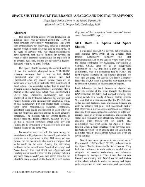
SPACE SHUTTLE FAULT TOLERANCE: ANALOG AND DIGITAL TEAMWORK<br />
Abstract<br />
The <strong>Space</strong> <strong>Shuttle</strong> control system (including the<br />
avionics suite) was developed during the 1970s to<br />
meet stringent survivability requirements that were<br />
then extraordinary but today may serve as a st<strong>and</strong>ard<br />
against which modern avionics can be measured. In<br />
30 years of service, only two major malfunctions<br />
have occurred, both due to failures far beyond the<br />
reach of fault tolerance technology: the explosion of<br />
an external fuel tank, <strong>and</strong> the destruction of a launchdamaged<br />
wing by re-entry friction.<br />
The <strong>Space</strong> <strong>Shuttle</strong> is among the earliest systems<br />
(if not the earliest) designed to a “FO-FO-FS”<br />
criterion, meaning that it had to Fail (fully)<br />
Operational after any one failure, then Fail<br />
Operational after any second failure (even of the<br />
same kind of unit), then Fail Safe after most kinds of<br />
third failure. The computer system had to meet this<br />
criterion using a Redundant Set of 4 computers plus a<br />
backup of the same type, which was (ostensibly!) a<br />
COTS type. Quadruple redundancy was also<br />
employed in the hydraulic actuators for elevons <strong>and</strong><br />
rudder. Sensors were installed with quadruple, triple,<br />
or dual redundancy. For still greater fault tolerance,<br />
these three redundancies (sensors, computers,<br />
actuators) were made independent of each other so<br />
that the reliability criterion applies to each category<br />
separately. The mission rule for <strong>Shuttle</strong> flights, as<br />
distinct from the design criterion, became “FO-FS,”<br />
so that a mission continues intact after any one<br />
failure, but is terminated with a safe return after any<br />
second failure of the same type.<br />
To avoid an unrecoverable flat spin during the<br />
most dynamic flight phases, the overall system had to<br />
continue safe operation within 400 msec of any<br />
failure, but the decision to shut down a computer had<br />
to be made by the crew. Among the interesting<br />
problems to be solved were “control slivering” <strong>and</strong><br />
“sync holes.” The first flight test (Approach <strong>and</strong><br />
L<strong>and</strong>ing only) was the proof of the pudding: when a<br />
key wire harness solder joint was jarred loose by the<br />
<strong>Shuttle</strong>’s being popped off the back of its 747 mother<br />
Hugh Blair-Smith, Down to the Metal, Dennis, MA<br />
(formerly of C. S. Draper Lab, Cambridge, MA)<br />
978-1-4244-4078-8/09/$25.00 ©2009 IEEE. 6.B.1-1<br />
ship, one of the computers “went bananas” (actual<br />
quote from an IBM expert).<br />
MIT Roles In Apollo And <strong>Space</strong><br />
<strong>Shuttle</strong><br />
I was never on NASA’s payroll, but worked as a<br />
staff member (1959-1981) at the Charles Stark<br />
Draper Laboratory, formerly the MIT<br />
Instrumentation Lab in the Apollo years when it was<br />
the prime contractor for Guidance, Navigation &<br />
Control. CSDL, spun off as an independent<br />
corporation in 1973 but still a part of the MIT<br />
community, was in a consulting role to NASA <strong>and</strong><br />
IBM Federal Systems in the <strong>Shuttle</strong> program. We<br />
who had designed the Apollo Guidance Computer<br />
knew that NASA wasn’t going that way again, so we<br />
re-invented ourselves as fault tolerance experts.<br />
<strong>Fault</strong> tolerance for hard failures in Apollo was<br />
relatively simple: if the crew thought the Primary<br />
GN&C System (PGNCS) had stopped working, they<br />
would switch to a totally different backup system.<br />
We took that as a requirement that the PGNCS shall<br />
suffer no such failures, ever, <strong>and</strong> moved heaven <strong>and</strong><br />
earth to achieve that goal—<strong>and</strong> succeeded! Part of<br />
that effort was a not-so-simple approach to computer<br />
recovery from transient faults: readiness to stifle lowpriority<br />
tasks in overload conditions, <strong>and</strong> saving the<br />
status quo frequently <strong>and</strong> effectively rebooting (very<br />
quickly) when things got too weird. That<br />
combination was what saved the Apollo 11 lunar<br />
l<strong>and</strong>ing when a radar interface went haywire; don’t<br />
let Richard Nixon [1] or anyone else tell you that the<br />
computer “failed” <strong>and</strong> a heroic human took over <strong>and</strong><br />
saved the day!<br />
NASA was under pressure to maximize use of<br />
Commercial Off-The-Shelf (COTS) subsystems in<br />
the <strong>Space</strong> <strong>Shuttle</strong>, theoretically for economy. They<br />
had less confidence in such units, as we did, <strong>and</strong> so<br />
designed in massive redundancy <strong>and</strong> advanced<br />
techniques to manage it. Thus it was that our role<br />
focused on working with NASA on the architecture<br />
of the whole vehicle to make the analog <strong>and</strong> digital<br />
parts cooperate in fault tolerance, <strong>and</strong> specifically
debating with IBM Federal Systems on how to give<br />
the spacecraft computers “instantaneous” fault<br />
tolerance.<br />
Aside from confidence in suppliers, another<br />
issue that excited the crews’ interest in high<br />
reliability was that the <strong>Shuttle</strong> would be one of the<br />
first aircraft to implement control in the “fly-by-wire”<br />
mode. It was all very well for Apollo-style spacecraft<br />
to be fly-by-wire because pilots hadn’t known any<br />
other type, but if it looked <strong>and</strong> flew more like an<br />
airplane, the astronauts tended to remember how<br />
good it felt to know that there were strong steel<br />
cables between their h<strong>and</strong> controls <strong>and</strong> the aerosurfaces,<br />
albeit with a power boost from hydraulics.<br />
It was our very good fortune to have Bob Crippen as<br />
the astronaut expert in this area, with his broad <strong>and</strong><br />
deep underst<strong>and</strong>ing of what we were doing.<br />
Once we were satisfied that the Orbiter<br />
architecture would support analog-digital teamwork<br />
(as in Apollo, we weren’t involved with the booster),<br />
we focused primarily on the Flight Computer<br />
Operating System (FCOS), which in turn was<br />
focused on task management, including redundancy<br />
management, among the General Purpose Computers<br />
(GPCs) <strong>and</strong> the sensors <strong>and</strong> actuators. It wasn’t any<br />
sort of a DOS (since there were no disk drives), <strong>and</strong> it<br />
didn’t have to h<strong>and</strong>le directly the crew displays <strong>and</strong><br />
inputs, as there are separate Display Electronics Units<br />
(DEUs) for that. The focus on task management was<br />
well suited to our experience in the same area in<br />
Apollo, whose multi-tasking “executive” was much<br />
too simple to be called an Operating System. As<br />
we’ll see, the exact architecture of the priorityoriented<br />
task management was crucial to our<br />
approach to redundancy management.<br />
Reliability Requirements And Degrees<br />
Perhaps the biggest difference between Apollo<br />
<strong>and</strong> the <strong>Shuttle</strong> was the degree to which the latter,<br />
though a glider, had to emulate a regular powered<br />
aircraft. One requirement is for a cross-range<br />
capability of 1500 miles, meaning that the airframe<br />
has to be highly maneuverable—the downside of that<br />
is a capability (if not properly controlled) of going<br />
into an unrecoverable flat spin during descent. It was<br />
soon determined that “properly controlled” meant no<br />
major defects in control could last longer than 400<br />
msec. Obviously, the crew couldn’t switch to a<br />
backup system under that constraint, so fully<br />
6.B.1-2<br />
automatic recovery from any single failure became a<br />
requirement. Such a recovery can be categorized as<br />
either Fail Safe (FS) or Fail Operational (FO),<br />
depending on whether the mission is aborted or<br />
allowed to continue undiminished after that failure.<br />
Since <strong>Shuttle</strong> missions can be quite long (weeks),<br />
treating the first recovery as FO requires an equally<br />
fully automatic recovery from a second failure, even<br />
of the same type of unit. The only relief in that<br />
requirement is an assumption that failures do not<br />
happen simultaneously; that there’s time to clean up<br />
the configuration after a first failure before a second<br />
failure of the same type takes place. The combination<br />
of two similar failures can then be called either FO-<br />
FS or FO-FO, depending on whether an abort is<br />
called on the second failure. The presence of an<br />
independent backup system, which the crew can<br />
switch to after a third failure if it doesn’t happen in<br />
one of those control-critical moments, suggests that<br />
the <strong>Shuttle</strong> avionics architecture could be called FO-<br />
FO-FS—Fail Operational-Fail Operational-Fail<br />
Safe—well, mostly safe anyway. NASA’s mission<br />
rules take the conservative approach of the FO-FS<br />
level, since two failures of one type of unit may not<br />
be a coincidence.<br />
Reliability Approach Throughout<br />
The deliberations on vehicle-wide fault tolerance<br />
architecture settled on quadruple modular redundancy<br />
(QMR) with voting for critical units, with a<br />
sprinkling of triple modular redundancy (TMR) with<br />
voting for units that were the best but not the only<br />
way to do their jobs, <strong>and</strong> a few dual-redundant, less<br />
critical, units. To obtain the benefits of analog-digital<br />
teamwork, this approach extended well beyond<br />
GPCs: to data buses, peripheral electronics, <strong>and</strong> even<br />
hydraulics, where servovalves driving secondary<br />
actuators perform QMR voting of their own.<br />
The advantage of modular redundancy with<br />
voting is that reliability does not depend on built-in<br />
tests, which can always be shown to have incomplete<br />
coverage; the challenge is that voting requires strict<br />
rules for which signals or actions are enough alike to<br />
be considered the same (<strong>and</strong> thus qualified to be part<br />
of the majority). Units with significant analog parts<br />
have to be forgiven differences within a tolerance,<br />
while all-digital units must produce identical results.<br />
Given this, <strong>and</strong> given the stipulation that failures<br />
happen one at a time, QMR voting is 4-out-of-4
initially, then 3-out-of-4 when a failure occurs; then it<br />
becomes TMR by ceasing to try working with the<br />
failed unit. Similarly, TMR votes 3-out-of-3 until one<br />
of those 3 fails, then 2-out-of-3. As you can’t make a<br />
majority out of an electorate of 2, the only assured<br />
recovery from a third failure is a resort to the<br />
independent backup.<br />
Voting With Multi-Port Hydraulics<br />
Before getting into the computer system, let’s<br />
look at how the secondary hydraulic actuators<br />
achieve the FO-FO-FS st<strong>and</strong>ard when moving the<br />
aero control surfaces: elevons, rudder, <strong>and</strong> body flap.<br />
Each of these surfaces is driven by a large powerful<br />
primary actuator which in itself must never fail, just<br />
as each wing must never fail. Hydraulic pressure is<br />
fed into the secondary actuator by 4 servovalves, any<br />
one of which can feed in the full pressure. If 3 of<br />
them call for deflection up <strong>and</strong> 1 calls for deflection<br />
down, the majority overpower the minority in feeding<br />
pressure to the primary actuator. When the minority<br />
servovalve is closed <strong>and</strong> locked by disabling its<br />
servoamplifier, there is still 2-out-of-3 hydraulic<br />
voting (Figure 1).<br />
Figure 1. Hydraulic Actuator Voting<br />
6.B.1-3<br />
<strong>Teamwork</strong> With QMR Actuator Servos<br />
Since the hydraulic actuators are used in the<br />
critical phases of descent, approach, <strong>and</strong> l<strong>and</strong>ing,<br />
their relationship to GPCs <strong>and</strong> data buses is the key<br />
to the digital fault tolerance. During critical phases,<br />
the 4 GPCs running the Primary Avionics Software<br />
System (PASS—a fifth GPC is running the Backup<br />
Flight System) are configured as a Redundant Set<br />
(RS) with each GPC driving one of the Flight Critical<br />
data buses, <strong>and</strong> each of those buses controls one<br />
servoamplifier at each secondary actuator. Thus<br />
every primary/ secondary actuator set is driven by the<br />
entire RS with a FO-FO level of fault tolerance<br />
As suggested above, <strong>Shuttle</strong> avionics is a system<br />
of distributed computers, with many local processors<br />
in addition to the GPCs. Most of these are designated<br />
by the functional name of Modulator/Demodulator<br />
(MDM) because of their dependence on direction<br />
from the data buses, but they are in fact embedded<br />
processors capable of interpreting polling queries <strong>and</strong><br />
actuator comm<strong>and</strong>s from a GPC, controlling<br />
whatever subsystem they belong to, <strong>and</strong> returning<br />
sensor data to the entire RS. The fact that they<br />
communicate with the GPCs by whole coherent<br />
messages is important because it allows the GPCs to<br />
be synchronized at a fairly coarse granularity, as<br />
opposed to, say, every instruction execution.<br />
Figure 2 shows all the data paths involved when<br />
GPCs in the RS send comm<strong>and</strong> messages to a typical<br />
actuator (shown schematically in the upper right<br />
corner). A comm<strong>and</strong> message is a coherent semantic<br />
unit with a content such as “Go to +5º deflection for<br />
the next 40 msec.” The horizontal lines between<br />
GPCs <strong>and</strong> MDMs are the 4 aft-subsystem flight<br />
critical data buses, each controlled by one GPC. Each<br />
of the Flight Critical/Aft-subsystem MDMs (FA1-4)<br />
controls one ServoAmplifier (ASA). Note how the<br />
ΔP signals from the servovalves feed back into the<br />
ASAs <strong>and</strong> the Monitors, from which they are passed<br />
to the MDM. That’s how the GPCs can poll these<br />
MDMs to see whether any ΔP signal is so far out of<br />
line as to be adjudged a servo failure.
Figure 2. GPCs To MDMs To ASAs To Actuators<br />
<strong>Teamwork</strong> With Redundant Sensors<br />
For input data to the GPCs, the fault tolerance<br />
design requires that each GPC in the RS receive<br />
exactly the same data from the set of redundant<br />
copies of any sensor. The software examines the<br />
multiple instances of input data <strong>and</strong> applies a filtering<br />
rule appropriate to the unit <strong>and</strong> its degree of<br />
redundancy, e.g. average, intermediate value, etc. If<br />
all the digital gear is working, this will produce the<br />
exact same filtered data in all GPCs in the RS, plus<br />
the exact same opinion of which sensor data is out of<br />
line, if any. That’s important to keep the calculations<br />
identical throughout the RS. (Cases where not all the<br />
digital gear is working are covered further on.)<br />
The MDMs are omitted from Figure 3, but<br />
should be understood to be in the long horizontal<br />
lines, one per Rate Gyro. The cross-coupling shown<br />
is actually performed by the data buses, since each<br />
MDM sends its data on all 4 buses. This implies that<br />
the 4 MDMs cannot all transmit at once, which seems<br />
contrary to the principle of synchronized data<br />
gathering, but they do sample <strong>and</strong> hold the data as<br />
simultaneously as their respective controlling GPCs<br />
sent polling comm<strong>and</strong>s; then they take turns on the<br />
bus set using normal contention resolution.<br />
6.B.1-4<br />
Figure 3. GPCs In RS Listening To All Rate<br />
Gyros<br />
The Need For Exact Data Uniformity<br />
If TMR had been a fully satisfactory fault<br />
tolerance approach, it would have been good enough<br />
to make the 3 GPCs in a TMR-level RS acquire input<br />
data that was substantially though not bit-for-bit<br />
equal, <strong>and</strong> issue comm<strong>and</strong>s that are substantially<br />
though not bit-for-bit equal. Going to quad<br />
redundancy <strong>and</strong> achieving graceful degradation of<br />
many types of units poses a number of complications,<br />
but above all, a sort of “smoking gun” issue that<br />
establishes the need for identical data in all GPCs:<br />
“Control Slivering.” With 4 GPCs calculating<br />
maneuvers that are almost the same, the system could<br />
put actuators into a 2-against-2 force fight, resulting<br />
in no maneuver. For <strong>Shuttle</strong> purposes, we made this<br />
argument about a 180º roll maneuver (common<br />
enough for spacecraft), but in a conference with a<br />
commercial-aircraft orientation, perhaps we should<br />
talk about a 180º turn instead! This is not any kind of<br />
failure case. With all digital <strong>and</strong> analog units working<br />
within their design tolerances, 2 GPCs could call for<br />
a maneuver of +179.99º <strong>and</strong> the 2 others could call<br />
for a maneuver of -179.99º.
Method Of GPC Synchronization<br />
Having dictated exact uniformity of data in all<br />
GPCs in the RS, we had to define task management<br />
to support it. Part of the problem was that the GPCs<br />
weren’t really designed for strictly synchronized<br />
operation, so they were supplied with a set of<br />
interconnecting 28V discretes, such that 3 discretes<br />
(“sync lines”) from each GPC could be read as a 3-bit<br />
“sync code” by each of the other GPCs. What task<br />
management in the FCOS has to do, without violating<br />
the requirement for priority-driven task execution, is<br />
to establish enough levels of “sync points” to make<br />
all changes of priority level occur at the same point<br />
of logical flow in all GPCs. As a practical matter,<br />
there are only three occasions to switch to a different<br />
task: the normal end of a task, the expiration of a<br />
timer interval, <strong>and</strong> the completion of an input/output<br />
(I/O) operation. The timer <strong>and</strong> I/O occasions are the<br />
fundamental causes of program interrupts, but in<br />
computers as loosely coupled as these, there’s no<br />
way to force each interrupt to appear at exactly the<br />
same point in the logic flow in all GPCs.<br />
Our solution was to aggregate effective logic<br />
flow into much larger blocks than instruction<br />
executions, <strong>and</strong> to require a sync point when ready to<br />
pass from one to the next. Interrupts butt in wherever<br />
they can, as in any computer system, but they are not<br />
allowed to affect mission logic flow except under<br />
control of a sync point. To assure timely response to<br />
such tamed interrupts, we made a rule that every task<br />
has to invoke a “programmed sync point” at least<br />
every millisecond. (This would never work in an<br />
ordinary mainframe environment where many<br />
unrefined programs are running around without<br />
regard to rules <strong>and</strong> freezing the works with infinite<br />
loops <strong>and</strong> deadly embraces, but <strong>Shuttle</strong> software is<br />
built in a much more disciplined environment.) The<br />
expiration of a timer interval flags the next sync point<br />
to become a “timer sync point,” <strong>and</strong> an I/O<br />
completion flags the next sync point to become an<br />
“IOC sync point.” These flags take the form of<br />
priorities, with programmed sync points having the<br />
lowest priority, timer sync points the next higher, <strong>and</strong><br />
I/O completions the highest.<br />
These priority values are exchanged among<br />
GPCs as sync codes, via the sync lines mentioned<br />
above. The effect is that no GPC proceeds to a new<br />
logic block, either the next one in the same task or a<br />
different one that responds to an interrupt-level sync<br />
6.B.1-5<br />
point, until all GPCs have come to a common point in<br />
their logic flow <strong>and</strong> agree (under a timeout limit) on a<br />
priority level. That’s how synchronization with data<br />
uniformity is maintained throughout the RS in the<br />
absence of failures. Next we must consider how the<br />
synchronization scheme responds to failure<br />
conditions.<br />
Case 1: GPC “Total” Failure<br />
If a GPC fails, as happened on the first<br />
Approach <strong>and</strong> L<strong>and</strong>ing Test flight, it will either be a<br />
no-show at the next programmed sync point, or (if<br />
it’s running at all) may enter a sync point prematurely<br />
<strong>and</strong> see all the others as no-shows. Either way, the<br />
timeout limit leads to the conclusion that a failure to<br />
sync has occurred, <strong>and</strong> every GPC reaching this<br />
conclusion turns on an alarm light to alert the crew,<br />
who alone are empowered to shut down a GPC. The<br />
Computer Annunciation Matrix, described in a<br />
later section, presents enough information for a<br />
confident decision.<br />
Case 2: Sensor Failure<br />
If a sensor (or the MDM that provides the only<br />
access to it) fails, it’s essential that all GPCs in the<br />
RS perceive this failure on the same I/O cycle, so that<br />
they can simultaneously exclude it from their data<br />
filter <strong>and</strong> resolve not to listen to that sensor again.<br />
Whenever a sensor failure is simply an error in<br />
numerical value <strong>and</strong> doesn’t trigger a low-level I/O<br />
error condition, it can be caught by any of several<br />
“old-fashioned” software techniques: parity <strong>and</strong><br />
cyclic redundancy checks, reasonableness tests based<br />
on serial correlation or a check on uniformity within<br />
a tolerance with corresponding data from redundant<br />
sensors.<br />
Where there is a low-level I/O error, there is<br />
generally a fault in some digital subsystem, but it’s<br />
not always clear whether the fault lies in an MDM or<br />
bus (on the far side of the cross-coupling from the<br />
GPCs) or on the GPC side of the cross-coupling. That<br />
is, certain digital subsystem failures can present the<br />
appearance of a sensor/MDM failure to some GPCs<br />
but not to others, which leads into the next failure<br />
case.
Case 3: GPC Bus Receiver Failure<br />
If a GPC becomes unable to receive data from a<br />
particular data bus, it can’t by itself distinguish that<br />
case from a bus failure, an MDM failure, or a sensor<br />
failure. The importance of the distinction is of course<br />
that if all GPCs in the RS see the same problem, the<br />
GPCs must be working correctly <strong>and</strong> the “string”<br />
(bus/MDM/sensor) must be at fault, while if only one<br />
GPC sees a problem, it must take the blame as the<br />
failed unit so that the other GPCs can continue<br />
normal use of that string <strong>and</strong> sensor. For this reason,<br />
the number of sync codes was increased to<br />
distinguish normal I/O completion from I/O<br />
completion with errors. That part of the design went<br />
through several iterations, of which the version<br />
presented here is the simplest to describe but doesn’t<br />
lack any of the final functionality.<br />
Sync Code System (No I/O Errors)<br />
This section goes into more detail about how<br />
GPC synchronization resolves interrupt priority races<br />
<strong>and</strong> detects faults in any GPC’s logic flow, without<br />
getting into I/O errors. For these purposes, four sync<br />
codes are enough for each GPC to issue as shown in<br />
Table 1.<br />
Table 1. Basic Sync Codes (Binary)<br />
Code Interpretation<br />
000 No sync point requested<br />
001 Programmed sync point<br />
010 Timer interrupt<br />
011 I/O Completion interrupt<br />
In the absence of any interrupts, the GPC with<br />
the fastest clock gets to a programmed sync point<br />
first, issues sync code 001, <strong>and</strong> waits for the others in<br />
the RS to do likewise, but only long enough for the<br />
GPC with the slowest clock to catch up. If all the<br />
others turn up with code 001 within the time limit,<br />
this GPC proceeds into the next block of the current<br />
task. Any other GPC that doesn’t catch up within the<br />
tolerance on clock rates is considered by this GPC to<br />
be out of sync, <strong>and</strong> it removes that GPC from its<br />
record of the RS <strong>and</strong> lights the appropriate crew<br />
alarm, but then proceeds into the next block as usual.<br />
If there’s only 1 no-show out of the original 4, the<br />
“local” RS is reduced to 3; but if all the other 3 are<br />
no-shows, the local RS is reduced to 1, in which case<br />
6.B.1-6<br />
the lonely GPC does not attempt to enter any more<br />
sync points. Presumably, the lonely GPC is convicted<br />
of failure, but only the crew may turn it off.<br />
When a timer interrupt occurs in any GPC, it has<br />
no immediate effect but lies in wait for a<br />
programmed sync point. When that occurs, this GPC<br />
issues sync code 010 to propose that course to the<br />
RS, <strong>and</strong> waits for the others to agree on 010 within<br />
the time limit. Assuming for now that no I/O<br />
Complete interrupt occurs while this is going on, the<br />
sequence is similar to the 001 case, except that all<br />
GPCs that agree on code 010 proceed to process the<br />
timer interrupt <strong>and</strong> perform whatever change of task<br />
that implies. Processing either type of interrupt is<br />
simply a matter of elevating the priority of whatever<br />
task is supposed to follow the interrupt event, <strong>and</strong> is<br />
so quick that it doesn’t need to do a programmed<br />
sync point of its own. Also, any GPCs that fail to<br />
sync may be showing 001 rather than being noshows,<br />
but it’s a fail to sync just the same. If all but<br />
one of the RS agree on 010, the timer logic in the<br />
lonely GPC may have failed (stopped), but if only<br />
one winds up with 010 while the others time out<br />
agreeing on 001, its timer logic may be triggering<br />
falsely.<br />
When an I/O Complete interrupt occurs in any<br />
GPC, it also has no immediate effect but lies in wait<br />
for a programmed sync point. (For now, assume no<br />
timer interrupt occurs around this time.) When the<br />
programmed sync point occurs, this GPC issues sync<br />
code 011 to propose that course to the RS, <strong>and</strong> waits<br />
for the others to agree on 011 within the time limit.<br />
The sequence is again similar, except that all GPCs<br />
that agree on code 011 proceed to process the I/O<br />
completion <strong>and</strong> perform whatever task change that<br />
implies. If all but one of the GPCs agree on 011, the<br />
I/O logic in the lonely GPC may have failed, but if<br />
only one GPC winds up with 011 while the others<br />
time out agreeing on 001, its I/O completion logic<br />
may be triggering falsely.<br />
When both types of interrupt occur at<br />
approximately the same time, they may occur in the<br />
same or different orders in the GPCs, so an additional<br />
step is seen to be required whenever a timer sync<br />
code (010) has to yield to an I/O Completion code<br />
(011). The GPC observing this event maintains a<br />
record of it, <strong>and</strong> the next sync point to occur (most<br />
likely in the high-priority task invoked by the I/O<br />
completion) looks for it <strong>and</strong> issues 010, rather than
001, if it finds it. Thus, a timer interrupt that loses a<br />
close race with an I/O completion still gets processed<br />
within a millisecond—though whether the task it<br />
invokes has a higher or lower priority than the I/Otriggered<br />
task is another question. This combination<br />
case has more paths to enumerate (<strong>and</strong> to verify <strong>and</strong><br />
validate), but the priority organization of both the<br />
sync codes <strong>and</strong> the tasks triggered by the interrupt<br />
events keeps the task management fairly<br />
straightforward.<br />
Sync Code System (With I/O Errors)<br />
This section covers how GPC synchronization at<br />
I/O completion uses extended sync codes to<br />
determine the correct response to input errors<br />
detected by a GPC’s hardware-level checking. Since<br />
the sensors (including feedback from actuators) are<br />
organized into 4 strings, <strong>and</strong> since we don’t have to<br />
consider multiple simultaneous failures, four<br />
extended sync codes are added to the original four as<br />
shown in Table 2.<br />
Table 2. Full Set Of Sync Codes (Binary)<br />
Code Interpretation<br />
000 No sync point requested<br />
001 Programmed sync point<br />
010 Timer interrupt<br />
011 I/O Completion interrupt, no error<br />
100 I/O Completion, error on string 1<br />
101 I/O Completion, error on string 2<br />
110 I/O Completion, error on string 3<br />
111 I/O Completion, error on string 4<br />
At I/O Completion sync points, the codes 011,<br />
100, 101, 110, <strong>and</strong> 111 are all considered to be in<br />
“agreement” as far as synchronization goes, but the<br />
fault tolerance logic takes a second look at them as<br />
soon as synchronization is assured. If all GPCs in the<br />
RS reported code, say, 110, they all evict string 3<br />
data (for the sensor currently being sampled) from<br />
their filter calculations <strong>and</strong> resolve never to look at<br />
that sensor again.<br />
If just one GPC reports, say, 101, while all the<br />
rest of the RS report 011, the lonely GPC is judged to<br />
6.B.1-7<br />
have failed to sync after all, with the usual<br />
consequences. This is required because that GPC is<br />
unable to perform the same input filtering<br />
calculations as the others, <strong>and</strong> the others are not<br />
“willing” to reduce their input data set by eliminating<br />
data that they all received correctly. Under our rule<br />
about one failure at a time, the only combinations<br />
that have to be considered are as shown in Table 3,<br />
where A, B, <strong>and</strong> C designate GPCs other than Self.<br />
Table 3. I/O Sync Codes In A 4-GPC RS<br />
Self A B C Interpretation & Action<br />
011 011 011 011 No string fail; use all data<br />
011 011 011 1xx C failed sync; use all data<br />
011 011 1xx 011 B failed sync; use all data<br />
011 1xx 011 011 A failed sync; use all data<br />
1xx 011 011 011 Self failed sync; leave RS<br />
100 100 100 100 String 1 fail; use 2-3-4 data<br />
101 101 101 101 String 2 fail; use 1-3-4 data<br />
110 110 110 110 String 3 fail; use 1-2-4 data<br />
111 111 111 111 String 4 fail; use 1-2-3 data<br />
Although I’ve been using “sensor” in connection<br />
with the data being treated in this way, it’s important<br />
to realize that all the actuators include sensors to<br />
report back on their own performance, e.g. the ΔP<br />
feedback from the hydraulics. Similarly, subsystems<br />
that are primarily sensors often accept effector<br />
comm<strong>and</strong>s, e.g. alignment comm<strong>and</strong>s for IMUs. So<br />
most MDMs participate in two-way conversations.<br />
As stated above, not all the local processors are<br />
MDMs. Figure 4 lists all the types <strong>and</strong> shows how<br />
they are connected through the 7 different types of<br />
data buses to all 5 GPCs—one of which is running<br />
the backup software (BFS). The BFS GPC normally<br />
listens to all buses so as to stay current with the state<br />
of the vehicle, but does not comm<strong>and</strong> any bus except<br />
its own Intercomputer bus, but it comm<strong>and</strong>s all buses<br />
when backup mode is selected. Whatever the type of<br />
local processor, the data bus protocols for message<br />
format, contention resolution, etc. are the same as<br />
described above for MDMs.
Sync Point Routines And Sync Holes<br />
The only GPC code we at MIT generated was for<br />
the sync routines. In contrast to all the flight-related<br />
code, which was written in HAL/S (a very high-level<br />
engineering language incorporating vectors, matrices,<br />
<strong>and</strong> differential equations), the sync routines were in<br />
assembly language, more like kernel programming<br />
with every nerdy slick trick allowed, <strong>and</strong> all the<br />
microseconds carefully counted out. The central loop<br />
of each sync routine made use of the fact that all 15<br />
sync lines (3 from each of the 5 GPCs) could be read in<br />
by a single instruction <strong>and</strong> passed through a current RS<br />
mask to look for agreement, with about 10 μsec per<br />
iteration—remember, that was blazing fast in the<br />
1970s. This implied that with r<strong>and</strong>om phasing between<br />
the loops in various GPCs, one could exit a sync point<br />
as much as 10 μsec ahead of another.<br />
We spent vast amounts of effort searching for<br />
ways in which sync codes could change at such times<br />
that they could be seen differently by different GPCs,<br />
further complicated by the fact that each GPC had its<br />
own clock rate, <strong>and</strong> refined the code to minimize these<br />
Figure 4. <strong>Shuttle</strong> Data Bus Architecture<br />
6.B.1-8<br />
“sync holes.” Fortunately, we were doing this at a time<br />
when the main-engine people <strong>and</strong> the thermal-tile<br />
people were struggling with their development<br />
problems <strong>and</strong> taking all the blame for delays, which<br />
gave us time to grind the sync holes down to very<br />
small probabilities. As far as I know, no <strong>Shuttle</strong> flight<br />
has experienced one.<br />
Computer Annunciation Matrix<br />
Figure 5 shows this dedicated display that shows<br />
each GPC’s vote as to whether itself or some other<br />
GPC has failed to sync. It treats all 5 GPCs equally,<br />
relying on the crew to know which computer is running<br />
BFS <strong>and</strong> which PASS computers are the RS. As the<br />
labeling shows, the top row is GPC 1’s votes regarding<br />
each of the 5 GPCs, the second row is GPC 2’s votes,<br />
<strong>and</strong> so on. Correspondingly, each column displays the<br />
“peer group’s” opinion of one GPC. As long as there is<br />
no fail to sync, the whole matrix is dark. Any GPC’s<br />
vote against another GPC turns on a white light; when<br />
a GPC perceives that it has fallen out of the RS, it turns<br />
on the yellow light in the main diagonal. If the crew
turns off a GPC, the entire corresponding row <strong>and</strong><br />
column go dark so as not to clutter the unit’s possible<br />
later displays.<br />
Figure 5. Computer Annunciation Matrix: CAM<br />
Various patterns of lights are quite informative,<br />
<strong>and</strong> help the crew decide whether a GPC that failed to<br />
sync might be worth trying again in a later mission<br />
phase. For example, suppose that, in an RS of GPCs 1-<br />
4, GPC 2 finds that it’s the only one unable to read one<br />
of the buses, but is otherwise running normally.<br />
The pattern of Figure 6 suggests that GPC 2 might<br />
be usable again if some configurational change were<br />
made, e.g. giving it comm<strong>and</strong> of a different bus.<br />
6.B.1-9<br />
Figure 6. CAM After GPC 2 Failed To Sync<br />
The Proof Of The Pudding<br />
The first free-flight test of the prototype <strong>Space</strong><br />
<strong>Shuttle</strong>, Enterprise, was in 1977. It was carried aloft by<br />
a specially adapted Boeing 747 (still in use to ferry<br />
<strong>Shuttle</strong>s from Edwards AFB to Kennedy <strong>Space</strong> Center)<br />
<strong>and</strong> was popped off the mother ship’s back to perform<br />
the Approach <strong>and</strong> L<strong>and</strong>ing phases. At the instant of<br />
separation, the CAM pattern of Figure 6 appeared for a<br />
split second, then that of Figure 7, making it clear that<br />
GPC 2 was very sick indeed. The crew moded the<br />
GPC through STANDBY to OFF <strong>and</strong> the CAM went<br />
dark while the remaining RS of GPCs 1, 3, <strong>and</strong> 4<br />
controlled the vehicle to a smooth flawless l<strong>and</strong>ing.
Figure 7. CAM After GPC 2 Failed Completely<br />
The immediate reaction by some of the NASA<br />
<strong>and</strong> IBM people was that GPC 2’s troubles must have<br />
been caused by all that complicated fault tolerance<br />
logic dreamed up by those MIT “scientists” (a sort of<br />
cuss word in the mouths of some who had wearied of<br />
our harangues on making the scheme complete).<br />
Several MIT <strong>and</strong> IBM engineers pored over the postflight<br />
hex dumps of GPC 2’s memory, looking for very<br />
small-needle clues in a very large haystack. One of the<br />
best IBMers, Lynn Killingbeck, concluded that it<br />
looked like the computer had “gone bananas” <strong>and</strong> that<br />
turned out to be exactly right. When the GPC was<br />
returned to IBM’s hardware labs, they found that the<br />
wire harness connecting its I/O Processor (IOP, see<br />
Figure 4) to its CPU had one cold-solder joint that had<br />
been jolted loose by the release from the 747. As luck<br />
would have it, the wire in question triggered an ultrapriority<br />
interrupt as it rattled against its connector pin.<br />
Nothing that the software was trying to do was going<br />
to get anywhere with that going on—bananas, indeed!<br />
One of Lynn’s colleagues, in honor of his swift<br />
<strong>and</strong> accurate analysis, presented him with a varnished<br />
mahogany trophy featuring two bananas fresh from the<br />
grocery (Figure 8).<br />
6.B.1-10<br />
Figure 8. Lynn Killingbeck’s Desk Trophy<br />
In those days, IBM was a strict white-shirt <strong>and</strong><br />
sober-tie kind of organization, so it was no great<br />
surprise to learn that Lynn’s manager came along after<br />
a couple of days <strong>and</strong> observed that although the trophy<br />
was appropriate for the moment, it wasn’t the sort of<br />
thing that upheld IBM’s corporate image. “Lynn, we’d<br />
like to suggest that you eat the evidence,” he said in his<br />
resonant bass voice.<br />
A Heretical Observation<br />
It has long been orthodox, in both mainframe <strong>and</strong><br />
control computers, to emphasize the feature of program<br />
interrupts to support the time-sharing that is essential<br />
(in very different ways) to both application areas.<br />
While the <strong>Shuttle</strong> GPCs had this feature <strong>and</strong> used it,<br />
the GPC synchronization scheme described here goes a<br />
long way toward emulating a system in which no<br />
interrupts exist. In effect, each interrupt had to be<br />
encapsulated <strong>and</strong> prevented from altering the logic<br />
flow until the higher-level software was prepared to<br />
consider such alterations. I believe that verification of<br />
the <strong>Shuttle</strong> PASS software was made much easier <strong>and</strong><br />
quicker by thus reducing the variety of logic flow<br />
paths. Not many people remember that even in the<br />
Apollo Guidance Computer, a primitive precursor of<br />
this approach existed: jobs that had to be restartable<br />
after transient disturbances protected themselves by<br />
sampling a variable NEWJOB at convenient times.
As stated above, mainframes are generally timeshared<br />
between production programs <strong>and</strong> new<br />
programs under development. The latter must be<br />
expected to violate st<strong>and</strong>ards of good behavior (e.g.<br />
infinite loops), so that it’s critical for interrupts to seize<br />
control of the machine without any cooperation from<br />
them.<br />
In real-time control systems, by contrast, all<br />
software elements are necessarily production code,<br />
which has many reasons to comply with strict behavior<br />
protocols: jitter, transport lag, optimal disposition of<br />
cycle overruns, etc. From this base, it was not difficult<br />
to add a protocol for frequent sampling of the<br />
conditions that can alter logic flow by elevating the<br />
priority of one task over another—that is, to perceive<br />
the events that trigger interrupts in a way that actually<br />
used the interrupts but could easily have been done<br />
without them.<br />
So that’s the heresy: I suggest that real-time<br />
control computers may be better off without program<br />
interrupts than with them, emulating their effects<br />
without over-complicating the logic flows.<br />
References<br />
Almost all of this material is from my memory of<br />
the work we did at the time, supported by a few looks<br />
at “<strong>Digital</strong> Development Memos” produced by the<br />
CSDL group named in the acknowledgments below,<br />
plus illustrations (copied for use in slide shows) from<br />
documents by NASA, IBM, <strong>and</strong> Rockwell<br />
International’s <strong>Space</strong> Division. Feeling that references<br />
in a technical paper should cite resources that<br />
interested readers can access, I must say with regret<br />
that aside from a few memos in my basement, even I<br />
can’t lay h<strong>and</strong>s on the primary documents.<br />
6.B.1-11<br />
Nevertheless, I cannot forbear to include one reference,<br />
even if it is to a side issue:<br />
[1] Mindell, David A., 2008, <strong>Digital</strong> Apollo,<br />
Cambridge, MA, MIT Press, p. 232.<br />
Acknowledgements<br />
I must acknowledge my colleagues at the Charles<br />
Stark Draper Laboratory, Inc. with whom I worked on<br />
fault tolerance during the <strong>Space</strong> <strong>Shuttle</strong> Avionics<br />
development years, basically the 1970s: Division Head<br />
Eldon C. Hall, Group Leader Alan I. Green, Albert L.<br />
Hopkins, Ramon Alonso, Malcolm W. Johnston, Gary<br />
Schwartz, Frank Gauntt, Bill Weinstein, <strong>and</strong> others.<br />
NASA people who contributed to development<br />
include Bob Crippen, Cline Frasier, Bill Tindall, Phil<br />
Shaffer, Ken Cox, <strong>and</strong> many others.<br />
From IBM Federal Systems Division: Lynn<br />
Killingbeck, Steve Palka, Tony Macina, <strong>and</strong> more.<br />
From Rockwell International <strong>Space</strong> Division: Vic<br />
Harrison, Bob D’Evelyn, Ron Loeliger, Bob Peller,<br />
Gene O’Hern, Sy Rubenstein, Ken McQuade, <strong>and</strong><br />
more.<br />
Rich Katz, of the Office of Logic Design at<br />
NASA’s Goddard <strong>Space</strong> Flight Center, encouraged me<br />
to present this material in a Lessons Learned session at<br />
the 2006 MAPLD (Military-Aerospace Programmable<br />
Logic Devices) conference. While it does not address<br />
such devices, it does cover problems that participants<br />
needed to underst<strong>and</strong>, bringing forward solutions that<br />
had been developed a generation before.<br />
28th <strong>Digital</strong> Avionics Systems Conference<br />
October 25-29, 2009