Enhancing cellular network capacity with adaptive antennas - Ericsson
Enhancing cellular network capacity with adaptive antennas - Ericsson
Enhancing cellular network capacity with adaptive antennas - Ericsson

Create successful ePaper yourself
Turn your PDF publications into a flip-book with our unique Google optimized e-Paper software.
<strong>Enhancing</strong> <strong>cellular</strong> <strong>network</strong> <strong>capacity</strong><br />
<strong>with</strong> <strong>adaptive</strong> <strong>antennas</strong><br />
Sören Andersson, Bengt Carlqvist, Bo Hagerman and Robert Lagerholm<br />
Wireless <strong>cellular</strong> communication is continuing to grow unabated. In many<br />
areas of the world, the demand for <strong>cellular</strong> communication is so great that<br />
operators are tempted to push the <strong>capacity</strong> of their <strong>network</strong>s beyond levels<br />
that current technology can handle. As wireless data applications over<br />
<strong>cellular</strong> <strong>network</strong>s become more widespread, the pressure to increase<br />
<strong>capacity</strong> will become even more intense. Capacity in the 800 and 900 MHz<br />
bands, where bandwidth is restricted, is already becoming a limiting factor.<br />
At 1800 and 1900 MHz, where available bandwidth is greater, the path<br />
loss is also greater. Thus, in this frequency band, coverage is one major<br />
aspect to consider.<br />
There are a number of ways of enhancing <strong>capacity</strong> in a <strong>cellular</strong> <strong>network</strong>,<br />
including frequency hopping, power control, microcells, the introduction<br />
of half-rate codecs, and the introduction of <strong>adaptive</strong> <strong>antennas</strong> at the base<br />
station. Adaptive <strong>antennas</strong> have been the subject of increasing interest in<br />
recent years, and several manufacturers and operators have made them<br />
the focus of research and field trials. The main conclusions being drawn<br />
from <strong>Ericsson</strong>’s studies indicate that <strong>adaptive</strong> <strong>antennas</strong> enable tighter<br />
reuse of frequencies <strong>with</strong>in a <strong>cellular</strong> <strong>network</strong>—that is, they increase <strong>network</strong><br />
<strong>capacity</strong>. Adaptive <strong>antennas</strong> can also improve speech quality. Moreover,<br />
a step-by-step introduction of <strong>adaptive</strong> <strong>antennas</strong> into existing <strong>network</strong>s<br />
appears to be practical and economically feasible.<br />
The authors describe the results of <strong>Ericsson</strong>’s research as it relates to<br />
<strong>adaptive</strong> <strong>antennas</strong> in GSM and TDMA (IS-136) <strong>network</strong>s, the combined<br />
use of <strong>adaptive</strong> <strong>antennas</strong> and frequency-hopping techniques (in GSM <strong>network</strong>s),<br />
and the implementation of <strong>adaptive</strong> <strong>antennas</strong> in existing <strong>network</strong>s.<br />
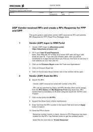
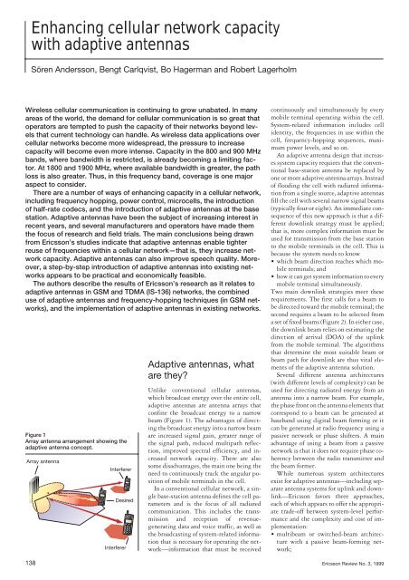
Figure 1<br />
Array antenna arrangement showing the<br />
<strong>adaptive</strong> antenna concept.<br />
Array antenna<br />
Interferer<br />
Desired<br />
Interferer<br />
Adaptive <strong>antennas</strong>, what<br />
are they?<br />
Unlike conventional <strong>cellular</strong> <strong>antennas</strong>,<br />
which broadcast energy over the entire cell,<br />
<strong>adaptive</strong> <strong>antennas</strong> are antenna arrays that<br />
confine the broadcast energy to a narrow<br />
beam (Figure 1). The advantages of directing<br />
the broadcast energy into a narrow beam<br />
are increased signal gain, greater range of<br />
the signal path, reduced multipath reflection,<br />
improved spectral efficiency, and increased<br />
<strong>network</strong> <strong>capacity</strong>. There are also<br />
some disadvantages, the main one being the<br />
need to continuously track the angular position<br />
of mobile terminals in the cell.<br />
In a conventional <strong>cellular</strong> <strong>network</strong>, a single<br />
base-station antenna defines the cell parameters<br />
and is the focus of all radiated<br />
communication. This includes the transmission<br />
and reception of revenuegenerating<br />
data and voice traffic, as well as<br />
the broadcasting of system-related information<br />
that is necessary for operating the <strong>network</strong>—information<br />
that must be received<br />
continuously and simultaneously by every<br />
mobile terminal operating <strong>with</strong>in the cell.<br />
System-related information includes cell<br />
identity, the frequencies in use <strong>with</strong>in the<br />
cell, frequency-hopping sequences, maximum<br />
power levels, and so on.<br />
An <strong>adaptive</strong> antenna design that increases<br />
system <strong>capacity</strong> requires that the conventional<br />
base-station antenna be replaced by<br />
one or more <strong>adaptive</strong> antenna arrays. Instead<br />
of flooding the cell <strong>with</strong> radiated information<br />
from a single source, <strong>adaptive</strong> <strong>antennas</strong><br />
fill the cell <strong>with</strong> several narrow signal beams<br />
(typically four or eight). An immediate consequence<br />
of this new approach is that a different<br />
downlink strategy must be applied;<br />
that is, more complex information must be<br />
used for transmission from the base station<br />
to the mobile terminals in the cell. This is<br />
because the system needs to know<br />
• which beam direction reaches which mobile<br />
terminals; and<br />
• how it can get system information to every<br />
mobile terminal simultaneously.<br />
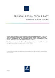
Two main downlink strategies meet these<br />
requirements. The first calls for a beam to<br />
be directed toward the mobile terminal; the<br />
second requires a beam to be selected from<br />
a set of fixed beams (Figure 2). In either case,<br />
the downlink beam relies on estimating the<br />
direction of arrival (DOA) of the uplink<br />
from the mobile terminal. The algorithms<br />
that determine the most suitable beam or<br />
beam path for downlink are thus vital elements<br />
of the <strong>adaptive</strong> antenna solution.<br />
Several different antenna architectures<br />
(<strong>with</strong> different levels of complexity) can be<br />
used for directing radiated energy from an<br />
antenna into a narrow beam. For example,<br />
the phase front on the antenna elements that<br />
correspond to a beam can be generated at<br />
baseband using digital beam forming or it<br />
can be generated at radio frequency using a<br />
passive <strong>network</strong> or phase shifters. A main<br />
advantage of using a beam from a passive<br />
<strong>network</strong> is that it does not require phase coherency<br />
between the radio transmitter and<br />
the beam former.<br />
While numerous system architectures<br />
exist for <strong>adaptive</strong> <strong>antennas</strong>—including separate<br />
antenna systems for uplink and downlink—<strong>Ericsson</strong><br />
favors three approaches,<br />
each of which appears to offer the appropriate<br />
trade-off between system-level performance<br />
and the complexity and cost of implementation:<br />
• multibeam or switched-beam architecture<br />
<strong>with</strong> a passive beam-forming <strong>network</strong>;<br />
138 <strong>Ericsson</strong> Review No. 3, 1999
• switched interleaved beams in the downlink;<br />
and<br />
• fully steerable beams.<br />
The passive beam-forming solution is the<br />
least complex one. Because the direction of<br />
arrival can identify the best uplink beam,<br />
phase coherency is not needed for the uplink<br />
or downlink.<br />
The second solution, which requires additional<br />
downlink beams, forms beams differently<br />
in the uplink and downlink. In the<br />
uplink, the number of beams is limited by<br />
the number of receiver branches. The direction<br />
of arrival is calculated from the uplink<br />
information. This information (the DOA) is<br />
then used to select a beam from a larger set<br />
of downlink beams. In the downlink, several<br />
parallel beam-forming <strong>network</strong>s are present.<br />
After the beam has been formed, the<br />
signals to the antenna elements are combined.<br />
Compared to the steerable-beam approach,<br />
this method reduces the phase coherency<br />
requirements in the downlink. An<br />
accurate direction-of-arrival estimate might<br />
require coherent receiver branches and calibration<br />
in the uplink.<br />
The fully steerable solution requires an individual<br />
transmitter for each antenna element<br />
plus phase coherency of the branches<br />
on the receiving and transmitting sides. The<br />
main advantage of this solution is that beam<br />
forming on the downlink is not limited to<br />
Multibeam<br />
a fixed set of beams or beam shapes. Moreover,<br />
this solution has the potential to reduce<br />
interference on the downlink via<br />
nulling; that is, by forming the beam <strong>with</strong><br />
reduced gain toward interfered co-channel<br />
mobile terminals.<br />
<strong>Ericsson</strong>’s <strong>adaptive</strong> antenna program has<br />
included extensive field trials for GSM and<br />
TDMA (IS-136) in cooperation <strong>with</strong> two<br />
major <strong>network</strong> operators, Mannesmann<br />
Mobilfunk and AT&T Wireless Services.<br />
One objective of the trials was to determine<br />
how <strong>adaptive</strong> <strong>antennas</strong> might be used in different<br />
propagation environments—urban,<br />
suburban, hilly, and rural areas. An important<br />
system-level verification from the trials<br />
is that the use of <strong>adaptive</strong> <strong>antennas</strong> enhances<br />
<strong>network</strong> quality by decreasing <strong>network</strong><br />
interference. In particular, the narrow<br />
beams reduce received interference in the<br />
uplink and the distribution of interference<br />
in the downlink (Figures 3 and 4).<br />
GSM and TDMA<br />
Steerable beam<br />
Sector beam<br />
As could be expected, differences in the<br />
GSM and TDMA standards carry over to the<br />
application of <strong>adaptive</strong> antenna technology.<br />
For example, TDMA does not currently support<br />
frequency hopping capability. Similarly,<br />
the TDMA specification requires that the<br />
base station output power on each carrier fre-<br />
Figure 2<br />
Steerable beam and switched multibeam<br />
<strong>antennas</strong> in <strong>network</strong> <strong>with</strong> cells.<br />
BOX A, ABBREVIATIONS<br />
BCCH Broadcast common control channel<br />
C/I Signal-to-interference ratio<br />
DOA Direction of arrival<br />
GSM Global system for mobile communication<br />
TDMA Time-division multiple access<br />
<strong>Ericsson</strong> Review No. 3, 1999 139
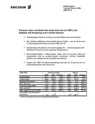
Adaptive<br />
trancievers<br />
AA verfication module<br />
Figure3<br />
Field trial equipment used in live-traffic TDMA <strong>network</strong>.<br />
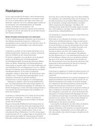
Figure 4<br />
Field trial equipment used in live-traffic<br />
GSM <strong>network</strong>.<br />
BCCH<br />
trancievers<br />
Adaptive<br />
trancievers<br />
Switching unit<br />
AA feeders<br />
Three sectors<br />
existing feeders<br />
quency be held at a constant level for the duration<br />
of the frame once one of three available<br />
time slots is occupied. However, a proposal<br />
has been made to change the specification<br />
to allow beam forming and individual<br />
power control for each time slot. The current<br />
TDMA specification prevents the introduction<br />
of downlink beam forming and beam<br />
switching individually for each time slot. It<br />
is nonetheless possible to form beams on the<br />
downlink on a carrier basis. With a carrierbased<br />
beam-forming strategy, performance<br />
can be improved by introducing beam packing,<br />
whereby the system allocates slots on the<br />
same carrier frequency to mobile terminals<br />
that share a similar line of direction from the<br />
base station. Simulations indicate that this<br />
technique increases <strong>capacity</strong> in TDMA <strong>network</strong>s<br />
by approximately 75 to 130%, depending<br />
on system parameters.<br />
With <strong>cellular</strong> <strong>network</strong>s, <strong>adaptive</strong> <strong>antennas</strong><br />
offer two ways of increasing <strong>network</strong> <strong>capacity</strong>:<br />
• using carrier signal-to-interference (C/I)<br />
gain to implement tighter frequency<br />
reuse; and<br />
• using fractional loading.<br />
The most straightforward solution is to use<br />
C/I gain to obtain tighter frequency reuse.<br />
For GSM <strong>network</strong>s, this approach can reduce<br />
the average reuse from nine to four, and<br />
typically improves <strong>capacity</strong> by100 to 120%<br />
for a C/I gain of 5 to 6 dB. What is more,<br />
field trials during regular commercial conditions<br />
in existing <strong>network</strong>s have shown<br />
that frequency reuse in TDMA <strong>network</strong>s can<br />
potentially be reduced from 21 to 12 or even<br />
9 when <strong>adaptive</strong> <strong>antennas</strong> are used together<br />
<strong>with</strong> downlink power control.<br />
Fractional loading regimes have even<br />
tighter frequency reuse—as much as one to<br />
three. Network quality is maintained when<br />
only a fraction of the frequencies are used simultaneously,<br />
hence the term fractional<br />
loading. This technique is usually applied<br />
in combination <strong>with</strong> radio-<strong>network</strong> features,<br />
such as frequency hopping, power<br />
control, and discontinuous transmission.<br />
The increase in <strong>capacity</strong> that results from<br />
fractional loading depends on a wide range<br />
of variables, such as frequency reuse, C/I<br />
gain, discontinuous transmission, and<br />
power control. However, field trials and<br />
system-level simulations have shown that<br />
fractional loading has the potential to increase<br />
<strong>capacity</strong> in GSM <strong>network</strong>s by as much<br />
as 280% under regular conditions.<br />
The combination of <strong>adaptive</strong> <strong>antennas</strong><br />
and frequency hopping in GSM <strong>network</strong>s<br />
offers the greatest potential for increasing<br />
<strong>capacity</strong>. Moreover, existing cell sites can be<br />
used to provide <strong>capacity</strong> increases over a<br />
large area.<br />
C/I gain and fractional loading do not<br />
have the same effect on the characteristics of<br />
system interference. C/I gain brings interferers<br />
closer together, whereas when fractional<br />
loading is applied they remain in the<br />
same position.<br />
A benefit of frequency hopping is that frequency<br />
diversity balances the quality between<br />
slow- and fast-moving users. Frequency<br />
hopping also introduces interference<br />
diversity, which improves performance.<br />
Strong interferers are shared by different<br />
users; time-varying interference increases<br />
interleaving and coding efficiency, which<br />
improves receiver performance.<br />
Although complex to implement, fractional<br />
loading <strong>network</strong>s that use frequencyhopping<br />
techniques are efficient. This<br />
premise is supported by system-level simulations<br />
in which each <strong>adaptive</strong> antenna base<br />
station was equipped <strong>with</strong> eight fixed<br />
beams. The results showed that interference<br />
diversity is always obtained regardless of<br />
140 <strong>Ericsson</strong> Review No. 3, 1999<br />
44 cm<br />
66 cm
traffic load and interference-reducing techniques,<br />
such as discontinuous transmission<br />
and power control. This is not the case for<br />
<strong>network</strong>s <strong>with</strong> conventional omnidirectional<br />
or sector <strong>antennas</strong>. The simulations also<br />
showed that GSM <strong>network</strong>s that combine<br />
<strong>adaptive</strong> antenna arrays and frequency hopping<br />
are spectrum-efficient, cope <strong>with</strong> tight<br />
frequency reuse, and considerably improve<br />
mobile tracking performance.<br />
Implementation in existing<br />
<strong>network</strong>s<br />
The cost of implementing an <strong>adaptive</strong> antenna<br />
solution depends on the complexity<br />
of the solution, the desired ease of implementing<br />
it, the target level of <strong>network</strong> quality,<br />
and the desired increase in <strong>capacity</strong>.<br />
Simulation trials using actual cell and data<br />
traffic supplied by Mannesmann Mobilfunk<br />
suggest that a cost-effective, step-by-step<br />
migration from a conventional antenna solution<br />
to one based on <strong>adaptive</strong> <strong>antennas</strong> is<br />
feasible. The simulation trials, which were<br />
based on existing radio <strong>network</strong>s, also<br />
showed that by installing only a few <strong>adaptive</strong><br />
antenna base stations, operators could<br />
improve the overall quality of the <strong>network</strong><br />
Figure 5).<br />
Most operators are expected to approach<br />
the migration in a step-by-step fashion,<br />
since doing so is more manageable and costeffective.<br />
The majority of today’s <strong>cellular</strong><br />
<strong>network</strong>s are composed of a mixture of large<br />
macrocells and smaller microcells. <strong>Ericsson</strong>’s<br />
field trials in commercial <strong>network</strong>s<br />
were based on implementing <strong>adaptive</strong> <strong>antennas</strong><br />
in a macrocell. Three alternatives<br />
have been identified for<br />
• boosting <strong>capacity</strong>—interference reduction<br />
means tighter frequency reuse and an<br />
increase in transceivers;<br />
• saving frequency spectrum—instead of<br />
increasing the number of transceivers, the<br />
current traffic can be served by fewer frequencies;<br />
and<br />
• reducing interference—a reduction in<br />
macrocell-to-microcell disturbance makes<br />
it possible to increase <strong>capacity</strong> by reusing<br />
frequencies in the microcell layer.<br />
The study considered cell relationships, the<br />
impact that introducing an <strong>adaptive</strong> antenna<br />
array would have on those relationships,<br />
and the addition of frequencies in the<br />
target cell and surrounding cells. Uplink<br />
performance was also investigated, as were<br />
the effects of introducing several <strong>adaptive</strong><br />
<strong>antennas</strong> into a <strong>network</strong>. In each case, the<br />
Figure 5<br />
Migration strategy: Adaptive <strong>antennas</strong> are deployed in a few target cells. This reduces<br />
interference in several neighboring cells and substantially increases <strong>capacity</strong>.<br />
simulations showed that <strong>capacity</strong> and quality<br />
could be enhanced, and that the introduction<br />
of only a few <strong>adaptive</strong> antenna base<br />
stations can significantly reduce interference.<br />
Conclusion<br />
<strong>Ericsson</strong> has developed a system-level concept<br />
that uses <strong>adaptive</strong> antenna arrays to<br />
meet demands for greater <strong>capacity</strong> in <strong>cellular</strong><br />
communication <strong>network</strong>s.<br />
In GSM <strong>network</strong>s, the combination of<br />
<strong>adaptive</strong> <strong>antennas</strong> and frequency-hopping<br />
techniques is an especially attractive solution<br />
that has the potential to increase <strong>capacity</strong><br />
by nearly 300% at hot spots.<br />
In TDMA <strong>network</strong>s, the combination of<br />
<strong>adaptive</strong> <strong>antennas</strong> and downlink power control<br />
has the potential to reduce the frequency<br />
reuse pattern from 7/21 to 3/9.<br />
The introduction of only a few <strong>adaptive</strong><br />
antenna base stations can significantly reduce<br />
interference.<br />
Adaptive <strong>antennas</strong> make up an attractive<br />
solution that can be implemented in a practical,<br />
cost-effective, step-by-step process.<br />
<strong>Ericsson</strong> Review No. 3, 1999 141