Modelling Launcher Aerothermodynamics - ESA
Modelling Launcher Aerothermodynamics - ESA
Modelling Launcher Aerothermodynamics - ESA

Create successful ePaper yourself
Turn your PDF publications into a flip-book with our unique Google optimized e-Paper software.
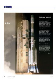
E<br />
urope’s access to space today relies<br />
primarily on the Ariane family of heavylift<br />
launchers and the future Vega launcher<br />
for smaller payloads. The successful<br />
development of such launchers critically<br />
depends on finding reliable solutions in the<br />
challenging areas of propulsion and<br />
aerothermodynamics, which are the key<br />
elements of any launch vehicle. The processes<br />
involved are highly complex because these<br />
disciplines strongly interact with the other build<br />
elements such as structures, thermal protection,<br />
acoustics, and guidance, navigation and control.<br />
To illustrate the aerothermodynamic challenges,<br />
we need only look at the various phases in the<br />
flight of a generic vehicle containing technology<br />
elements from both Ariane-5 and Vega.<br />
Introduction<br />
In the past, the aerodynamic and<br />
aerothermodynamic development work on<br />
vehicles such as the Space Shuttle or<br />
Ariane-4 has been based almost exclusively<br />
on engineering and empirical methods and<br />
experiments. In the last two decades,<br />
however, Computational Fluid Dynamics<br />
(CFD) has matured to a point where it can<br />
make meaningful contributions when fast<br />
analytical modelling requires that the<br />
physical problem be strongly simplified,<br />
and testing is either extremely expensive<br />
or cannot recreate the real problem.<br />
Increasingly, CFD-based methods offer the<br />
only feasible solution for accelerating and<br />
refining the space-transportation design<br />
process whilst still maintaining sufficient<br />
confidence in the results for safe design<br />
decisions to be made.<br />
The Launch Sequence<br />
T 0 – 12 hours: <strong>Launcher</strong> Roll-out<br />
The launcher is transported from the<br />
controlled environment of the integration<br />
hall to the launch pad, and into what may<br />
possibly be a ‘hostile’ environment due to<br />
rain or gusty winds. Aerodynamically, this<br />
may already be a problem because if a<br />
cylindrically shaped object, such as a tall<br />
building or launch vehicle, is exposed to<br />
sufficiently strong cross-winds, vortices<br />
formed in the wake of the structure cause<br />
pressure fluctuations, resulting in a<br />
fluctuating force on the object.<br />
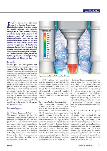
Snapshot of an unsteady flow field at the Ariane-5 launcher’s base<br />
CFD methods and simplifying<br />
analytical modeling are therefore used to<br />
determine critical wind velocities for the<br />
launcher structure on the launch pad,<br />
through the simulation of vortex shedding<br />
effects coupled with structural dynamics.<br />
This is a substantial help in determining<br />
critical roll-out and launcher installation<br />
conditions.<br />
T 0 – 7 seconds: Main-Engine Ignition<br />
After main-engine ignition, the<br />
development of the engines’ exhaust<br />
plumes and the blast wave characteristics<br />
determine the acoustic environment before<br />
lift-off, which has a direct impact on the<br />
acoustic vibration levels acting on the<br />
payload. As more and more stringent<br />
acoustic requirements are imposed on the<br />
launchers, aerodynamic optimisation of<br />
the launch-pad area by diverting the high<br />
noise level of the engine plume away from<br />
the launch vehicle becomes more<br />
important. CFD methods are currently<br />
used, together with subscale testing and<br />
empirical modelling, to predict the effect<br />
of the complex flow in the ducts that divert<br />
the exhaust plumes on the launch pad.<br />
Launch-Vehicle <strong>Modelling</strong><br />
Ignition of the main engine also involves<br />
high structural loads on the expansion<br />
nozzle due to a transient asymmetric<br />
flow field within the nozzle. Detailed<br />
knowledge of the physics of such unsteady<br />
flows allows one to arrive at a nozzle<br />
design that combines high efficiency<br />
with low operational risk. Due to the<br />
expense of conducting full-scale tests,<br />
such understanding is usually derived from<br />
a combination of subscale testing,<br />
empirical methods and sophisticated CFD<br />
methods.<br />
T 0 + 0-10 seconds: Solid Booster Ignition<br />
and Lift-off<br />
Lift-off takes place immediately after the<br />
ignition of the solid-rocket boosters.<br />
During the very first flight phase,<br />
especially if an early pitch-over manoeuvre<br />
is necessary to reach a planned trajectory,<br />
interactions between the hot main-engine<br />
and booster plumes and the ground<br />
facilities, e.g. launch tower and mobile<br />
gantry, have to be taken into account. A<br />
combination of empirical, analytical and<br />
numerical methods is used to assess<br />
critical parameters in this area.<br />
www.esa.int esa bulletin 120 - november 2004 41