Modelling Launcher Aerothermodynamics - ESA
Modelling Launcher Aerothermodynamics - ESA
Modelling Launcher Aerothermodynamics - ESA

Create successful ePaper yourself
Turn your PDF publications into a flip-book with our unique Google optimized e-Paper software.
Technical & Quality Management<br />
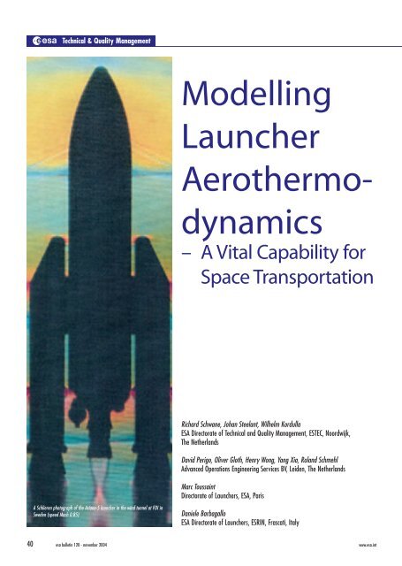
A Schlieren photograph of the Ariane-5 launcher in the wind tunnel at FOI in<br />
Sweden (speed Mach 0.85)<br />
<strong>Modelling</strong><br />
<strong>Launcher</strong><br />
Aerothermo-<br />
dynamics<br />
– A Vital Capability for<br />
Space Transportation<br />
Richard Schwane, Johan Steelant, Wilhelm Kordulla<br />
<strong>ESA</strong> Directorate of Technical and Quality Management, ESTEC, Noordwijk,<br />
The Netherlands<br />
David Perigo, Oliver Gloth, Henry Wong, Yang Xia, Roland Schmehl<br />
Advanced Operations Engineering Services BV, Leiden, The Netherlands<br />
Marc Toussaint<br />
Directorate of <strong>Launcher</strong>s, <strong>ESA</strong>, Paris<br />
Daniele Barbagallo<br />
<strong>ESA</strong> Directorate of <strong>Launcher</strong>s, ESRIN, Frascati, Italy<br />
40 esa bulletin 120 - november 2004 www.esa.int
E<br />
urope’s access to space today relies<br />
primarily on the Ariane family of heavylift<br />
launchers and the future Vega launcher<br />
for smaller payloads. The successful<br />
development of such launchers critically<br />
depends on finding reliable solutions in the<br />
challenging areas of propulsion and<br />
aerothermodynamics, which are the key<br />
elements of any launch vehicle. The processes<br />
involved are highly complex because these<br />
disciplines strongly interact with the other build<br />
elements such as structures, thermal protection,<br />
acoustics, and guidance, navigation and control.<br />
To illustrate the aerothermodynamic challenges,<br />
we need only look at the various phases in the<br />
flight of a generic vehicle containing technology<br />
elements from both Ariane-5 and Vega.<br />
Introduction<br />
In the past, the aerodynamic and<br />
aerothermodynamic development work on<br />
vehicles such as the Space Shuttle or<br />
Ariane-4 has been based almost exclusively<br />
on engineering and empirical methods and<br />
experiments. In the last two decades,<br />
however, Computational Fluid Dynamics<br />
(CFD) has matured to a point where it can<br />
make meaningful contributions when fast<br />
analytical modelling requires that the<br />
physical problem be strongly simplified,<br />
and testing is either extremely expensive<br />
or cannot recreate the real problem.<br />
Increasingly, CFD-based methods offer the<br />
only feasible solution for accelerating and<br />
refining the space-transportation design<br />
process whilst still maintaining sufficient<br />
confidence in the results for safe design<br />
decisions to be made.<br />
The Launch Sequence<br />
T 0 – 12 hours: <strong>Launcher</strong> Roll-out<br />
The launcher is transported from the<br />
controlled environment of the integration<br />
hall to the launch pad, and into what may<br />
possibly be a ‘hostile’ environment due to<br />
rain or gusty winds. Aerodynamically, this<br />
may already be a problem because if a<br />
cylindrically shaped object, such as a tall<br />
building or launch vehicle, is exposed to<br />
sufficiently strong cross-winds, vortices<br />
formed in the wake of the structure cause<br />
pressure fluctuations, resulting in a<br />
fluctuating force on the object.<br />
Snapshot of an unsteady flow field at the Ariane-5 launcher’s base<br />
CFD methods and simplifying<br />
analytical modeling are therefore used to<br />
determine critical wind velocities for the<br />
launcher structure on the launch pad,<br />
through the simulation of vortex shedding<br />
effects coupled with structural dynamics.<br />
This is a substantial help in determining<br />
critical roll-out and launcher installation<br />
conditions.<br />
T 0 – 7 seconds: Main-Engine Ignition<br />
After main-engine ignition, the<br />
development of the engines’ exhaust<br />
plumes and the blast wave characteristics<br />
determine the acoustic environment before<br />
lift-off, which has a direct impact on the<br />
acoustic vibration levels acting on the<br />
payload. As more and more stringent<br />
acoustic requirements are imposed on the<br />
launchers, aerodynamic optimisation of<br />
the launch-pad area by diverting the high<br />
noise level of the engine plume away from<br />
the launch vehicle becomes more<br />
important. CFD methods are currently<br />
used, together with subscale testing and<br />
empirical modelling, to predict the effect<br />
of the complex flow in the ducts that divert<br />
the exhaust plumes on the launch pad.<br />
Launch-Vehicle <strong>Modelling</strong><br />
Ignition of the main engine also involves<br />
high structural loads on the expansion<br />
nozzle due to a transient asymmetric<br />
flow field within the nozzle. Detailed<br />
knowledge of the physics of such unsteady<br />
flows allows one to arrive at a nozzle<br />
design that combines high efficiency<br />
with low operational risk. Due to the<br />
expense of conducting full-scale tests,<br />
such understanding is usually derived from<br />
a combination of subscale testing,<br />
empirical methods and sophisticated CFD<br />
methods.<br />
T 0 + 0-10 seconds: Solid Booster Ignition<br />
and Lift-off<br />
Lift-off takes place immediately after the<br />
ignition of the solid-rocket boosters.<br />
During the very first flight phase,<br />
especially if an early pitch-over manoeuvre<br />
is necessary to reach a planned trajectory,<br />
interactions between the hot main-engine<br />
and booster plumes and the ground<br />
facilities, e.g. launch tower and mobile<br />
gantry, have to be taken into account. A<br />
combination of empirical, analytical and<br />
numerical methods is used to assess<br />
critical parameters in this area.<br />
www.esa.int esa bulletin 120 - november 2004 41
Technical & Quality Management<br />
CFD modelling of the deformation, or so-called ‘ovalization’ of a Vulcain-2 engine nozzle due to asymmetric internal pressure loads<br />
Flow/structure coupling makes an<br />
important contribution to the structural<br />
noise level that is transmitted to the<br />
payload. Computational tools are used to<br />
describe the interaction of launcher<br />
oscillations with the flow for the most<br />
important structural modes.<br />
During the first flight phase, high heat<br />
loads are observed in the nozzle near the<br />
exit due to incipient separation of the flow<br />
in performance-optimised nozzles. Control<br />
of such heat loads again requires detailed<br />
knowledge of the nozzle flow, since a large<br />
separation could cause post combustion<br />
and overheating close to the nozzle’s exit.<br />
Experimental and numerical methods are<br />
used to determine the extent and severity<br />
of flow separation for this first highly overexpanded<br />
flow phase.<br />
T 0 + 30-50 seconds: <strong>Launcher</strong> in the<br />
Transonic Flight Regime<br />
The point where the launcher goes<br />
supersonic represents another critical<br />
phase. The local flow-field around the<br />
launcher becomes highly complex,<br />
including localised regions of supersonic<br />
flow terminated by strong shock waves<br />
with associated high pressure variations<br />
(see Schlieren photograph of Ariane-5 on<br />
title page).<br />
The flow-field is then highly sensitive to<br />
small changes in flight direction (pitch and<br />
yaw) and significant asymmetric loads<br />
may result from such motions. Moreover,<br />
the shock waves around the vehicle exhibit<br />
oscillations, and the resulting typical high<br />
frequency shock motion is another source<br />
of severe acoustic noise, against which<br />
measures must be taken, either by<br />
changing the shape or by protecting<br />
instruments or mechanisms located near<br />
the disturbances.<br />
Experience has shown that in this flight<br />
phase, the simulation and control of the<br />
interaction of the main engine plume and<br />
the ambient flow field requires the greatest<br />
attention because of the generation of side<br />
loads and large local heat loads.<br />
Uncontrolled side loads can also lead to<br />
malfunctioning of the gimbal system.<br />
However, since the complex aero-<br />
thermodynamics of separating flow in<br />
expansion nozzles and the coupling to the<br />
ambient flow field are not yet entirely<br />
understood, nozzles have to be designed<br />
with large margins and therefore cannot be<br />
fully optimised for both sea-level and<br />
rarefied atmospheric conditions.<br />
More sophisticated three-dimensional<br />
computational results, e.g. wall streamlines<br />
and velocity vector plots near the<br />
nozzle exit (see accompanying figure), as<br />
well as experimental data obtained both on<br />
the ground and in flight, are essential for<br />
an in-depth understanding of the flow<br />
physics and ultimately for shape<br />
improvements that reduce the loads to an<br />
acceptable level. Such results will be<br />
employed in future work on buffeting<br />
reduction through launcher shape<br />
optimisation.<br />
T 0 + 30 - 120 seconds: Ovalization of<br />
<strong>Launcher</strong> Nozzles<br />
Currently, analytical models are generally<br />
used in nozzle design to, for example,<br />
evaluate structural fatigue and nozzle<br />
42 esa bulletin 120 - november 2004 www.esa.int
Pressure distribution and Mach-number contours in plane of symmetry and streamlines past retro-covers for Vega<br />
deformation known as ‘ovalization’.<br />
However, due to the necessary<br />
simplifications for the complex coupled<br />
flow field, such models require the<br />
application of large safety factors, leading<br />
to non-optimal performance. Benefiting<br />
from today’s greatly improved computer<br />
performances with cost-efficient highperformance<br />
parallel-processing systems,<br />
the enhanced validation levels of CFD<br />
methods are becoming more and more<br />
important. For engine components, such as<br />
nozzles, recent coupling of flow with heat<br />
transfer as well as structural dynamics is<br />
leading to better understanding of the<br />
limiting structural loads, and hence to<br />
reduced design margins.<br />
Analytical models can only predict<br />
nozzle stability limits for separated flows.<br />
Very recent computational analysis has<br />
provided the first evidence that fully<br />
Low-pressure oxidiser pre-flow in the combustion chamber and nozzle of the Aestus engine<br />
attached flow can also excite nozzle<br />
ovalization. The accompanying illustration<br />
shows the CFD-predicted structural<br />
deformation response of a thin-walled<br />
nozzle under an internal pressure load.<br />
An exact quantitative analysis is<br />
currently being pursued, but already at this<br />
stage the conclusion that safety factors<br />
cannot replace a thorough understanding<br />
of the aerothermodynamic flow properties<br />
seems justified.<br />
T 0 +120 seconds: Flight at Maximum<br />
Dynamic Pressure<br />
Due to its increasing velocity and the<br />
decreasing ambient pressure, the launcher<br />
reaches a point on its trajectory where the<br />
ambient flow results in the highest<br />
dynamic loads on the launcher’s structure.<br />
It typically occurs at roughly twice the<br />
speed of sound, and not only the main<br />
Launch-Vehicle <strong>Modelling</strong><br />
structure of the launcher, but also<br />
protuberances such as wiring tunnels, fuel<br />
pipes and retro-rocket covers have to<br />
withstand such loads. Such local flow<br />
effects are strongly viscous-dominated and<br />
cannot be accurately modelled in sub-scale<br />
wind-tunnel experiments. CFD modelling<br />
of the flow has become an indispensable<br />
tool for the extrapolation of wind-tunnel<br />
results to actual flight conditions.<br />
The above figure shows CFD modelling<br />
results for a Vega-shaped vehicle travelling<br />
at Mach 2 at an altitude of approximately<br />
14 000 metres (angle of attack 3 deg and<br />
roll angle 45 deg).<br />
T 0 + 240-244 seconds: Ignition of Upper<br />
Stage Engine<br />
Typically 4 minutes into the flight, at<br />
hypersonic speeds and in rarefied<br />
atmospheric conditions, the first stage<br />
www.esa.int esa bulletin 120 - november 2004 43
Technical & Quality Management<br />
reaches the end of its lifetime and is<br />
pyrotechnically separated from the upperstage.<br />
Following a possible ballistic flight<br />
phase, the upper-stage engine is ignited in<br />
vacuum, involving the injection of<br />
pressurised liquid propellants into the<br />
combustion chamber, contact ignition, and<br />
an increase of pressure resulting in steady<br />
reacting flow.<br />
Upper-stage engines as Aestus have been<br />
designed by means of experiments<br />
including the simulation of ambient<br />
vacuum conditions for the cold pre-flow<br />
and extensive use of system-level<br />
simulation tools. To ensure a stable<br />
transition to nominal engine operation for<br />
a wide variety of initial conditions,<br />
customised 3D-CFD methods are used to<br />
analyse the dynamics of the initial low-<br />
The Sequence of Aerodynamic Events during a launch<br />
pressure flow processes in the engine’s<br />
feed system, combustion chamber and<br />
nozzle. Experience has shown that the<br />
transient priming of the fuel dome and the<br />
oxidiser pre-flow in the combustion<br />
chamber of the engine require special<br />
consideration to guarantee smooth and<br />
reliable operation.<br />
The start-up sequence also involves an<br />
oxidiser pre-flow phase to ensure welldefined<br />
flow conditions in the combustion<br />
chamber prior to fuel injection and contact<br />
ignition. This non-reacting low-pressure<br />
flow expands into vacuum and is<br />
characterised by a severe drop of oxidiser<br />
temperature and complex two-phase flow<br />
phenomena. Propellant and engine<br />
temperatures have a key influence on the<br />
pre-flow; however, these parameters can<br />
vary significantly, depending on the<br />
mission profile. Due to the complexity of<br />
experimental testing at vacuum conditions,<br />
3D-CFD analysis has recently been<br />
employed to assess this parametric<br />
influence in a cost- and time-efficient way<br />
and identify critical limits, such as icing of<br />
oxidiser, local accumulation on chamber<br />
walls, or backflow into the fuel dome.<br />
The figure on the previous page shows<br />
the flash-evaporating oxidiser spray (left),<br />
with the vapour flow field ranging from low<br />
subsonic conditions in the combustion<br />
chamber to supersonic conditions at the<br />
nozzle exit (middle), and the deposition of<br />
liquid oxidiser on the chamber walls (right).<br />
The second phase of this analysis addressed<br />
the dynamic evolution of the oxidiser<br />
spray during pre-flow, providing essential<br />
Time LV Condition Flow Problem Tool* Expected or Achieved Benefit<br />
T0-12 hours LV rolled out LV exposed to CFD, AM Launch cost reduction, risk<br />
environment mitigation<br />
T0-7 sec EPC ignition Blast wave CFD, EXP Improved payload environment,<br />
EPC start up loads risk mitigation<br />
T0 Lift-off Plume / ground CFD, EXP Cost reduction for ground facilities,<br />
interaction<br />
V2 with incipient<br />
separation<br />
AM risk mitigation<br />
T0 + 30-120 sec Transonic flow regime Side loads on EPC nozzle EXP, CFD, Permit LV performance<br />
Base buffeting impact<br />
on EPC<br />
AM optimisation<br />
T0 + 120 sec Max. dynamic pressure Loads on structure and<br />
protuberances<br />
CFD, EXP Structural design optimisation<br />
T0 + 240-244 sec Stage separation and Ignition of upper stage CFD, EXP Risk mitigation<br />
ignition of upper stage engine<br />
T0 + 244-251 sec Transients in HM7B Impact of HM7B plume CFD Risk mitigation<br />
start up on EPC<br />
* EXP: Experimental Methods CFD: Computational Fluid Dynamics AM: Analytical <strong>Modelling</strong><br />
44 esa bulletin 120 - november 2004 www.esa.int
CFD predictions for advanced nozzle concepts: left, pressure contours for a clustered aero-spike nozzle; right, wall-pressure contours for a dual-bell nozzle<br />
information for accurate system-level<br />
simulation of the engine start-up phase.<br />
T 0 + 244-250 seconds: Upper Stage<br />
Engine Plume Impact on the Main Stage<br />
The interaction of the plume from the<br />
starting of the upper-stage engine (e.g.<br />
HM7B) with the separated first stage<br />
(EPC) needs to be thoroughly investigated<br />
to avoid damage by high heat fluxes that<br />
could cause residual fuel in the tanks of the<br />
first stage to explode and thereby endanger<br />
the upper stage. Forces and moments on<br />
the first stage also have to be controlled to<br />
avoid stage collision due, for example, to<br />
interaction with the plume of a gimballed<br />
upper-stage engine nozzle.<br />
A computational study was performed to<br />
arrive at an improved estimate for the heat<br />
fluxes on the EPC dome for steady nozzle<br />
operation, assuming a constant position of<br />
the two stages relative to each other for the<br />
start-up process. The main conclusion of<br />
that investigation is that the heat-flux on<br />
the first stage fluctuates strongly, and the<br />
peaks by far exceed the time-averaged<br />
values. Hence, the usually applied steadystate<br />
flow simulations substantially underpredict<br />
the transient loads encountered.<br />
This could have been expected for the<br />
time-dependent engine start-up, but is in<br />
fact also true for steady HM7B operation.<br />
These results highlight the need for careful<br />
resolution of time-dependent flow<br />
phenomena for design purposes also.<br />
Advanced Nozzle Design<br />
The research activities mentioned so far in<br />
the context of the various stages in a<br />
launch scenario are mainly concerned with<br />
clarifying the aero/aerothermodynamic<br />
challenges faced with today’s launchers on<br />
the ground and in flight. Another essential<br />
task is to support the development of<br />
new launcher technologies aimed at<br />
overcoming existing limitations, for<br />
example in propulsion.<br />
Conventional nozzles for main-stage<br />
application typically expand the<br />
combustion products to pressure levels<br />
well below sea-level conditions in trying<br />
to optimise the overall nozzle performance<br />
for the entire flight envelope.<br />
Unfortunately, the higher ambient pressure<br />
at sea level results in a recompression of<br />
the plume and in potentially unstable flow<br />
separation within the nozzle. A direct<br />
consequence of such behaviour is the<br />
increased and unacceptable level of sideloads<br />
exerted on the nozzle structure. This<br />
limits the performance that may be derived<br />
from conventional nozzle designs by<br />
Launch-Vehicle <strong>Modelling</strong><br />
limiting the maximum area ratio that can<br />
be safely employed.<br />
Efforts thus concentrate on new nozzle<br />
concepts to meet the ambitious costreduction<br />
goals to maintain and increase<br />
the competitiveness of Europe’s launchers.<br />
This implies the need to consider also<br />
thrust-chamber design options that offer a<br />
substantial cost reduction, meeting overall<br />
performance requirements possibly at the<br />
expense of maximum specific impulse.<br />
Losses due to low-cost approaches for<br />
engine components and architectures may<br />
be compensated for by advanced nozzle<br />
designs allowing for altitude adaptation of<br />
the nozzle area ratio.<br />
Europe has already been successful in<br />
expanding the knowledge base relating<br />
to advanced nozzle concepts. The figure<br />
above shows two such concepts that have<br />
been, or are currently being investigated<br />
with <strong>ESA</strong>’s industrial partners. They are<br />
primarily designed to overcome the<br />
previously described separation problem<br />
by adapting the plume boundary pressure<br />
to that of the ambient environment.<br />
The application of advanced nozzle<br />
technology to upper-stage propulsion is<br />
also under active consideration due to the<br />
reduced packaging volumes inherent in<br />
several of the concepts.<br />
www.esa.int esa bulletin 120 - november 2004 45
Technical & Quality Management<br />
Today, European LO X /LH 2 engine<br />
nozzles rely on welded tubular wall<br />
structures for actively cooled configurations,<br />
such as the HM7B and Vulcain<br />
nozzles. This is a simple but not very costeffective<br />
solution due to the special<br />
rectangular tubes needed and the extensive<br />
welding procedures employed. Alternative<br />
design options offer reductions in recurring<br />
costs by using a laser-welded sandwich<br />
design for actively cooled parts. Further<br />
advantages include: a high stiffness and<br />
strength/mass ratio; greater flexibility in<br />
cooling-channel design to tailor cooling<br />
characteristics; more efficient use of the<br />
engine’s coolant pressure budget for nozzle<br />
cooling; and improved modelling accuracy,<br />
both from a mechanical and an<br />
aerodynamic point of view.<br />
A number of European research<br />
programmes are being initiated to look at<br />
the effects of both hot-gas and coolant<br />
flows on nozzle-wall heat transfer for such<br />
novel concepts. One such programme,<br />
under the management of the French Space<br />
Agency CNES, is focusing on Flow<br />
Separation Control Devices (FSCDs), with<br />
working-group members drawn both from<br />
industry (SNECMA, Volvo Aero Corp.,<br />
EADS-ST) and research organisations<br />
(DLR, ONERA, LEA Poitiers and<br />
<strong>ESA</strong>/ESTEC). A cornerstone of the<br />
group’s work is the development of a<br />
scaling logic from subscale cold testing,<br />
via subscale hot testing, to flight<br />
configurations. At the subscale level, cold<br />
and hot techniques are both deemed vital<br />
and neither are sufficient in isolation. Used<br />
in conjunction, however, they become a<br />
powerful propulsion-system design tool.<br />
While cold-flow experiments are ideal<br />
for several of the tasks in hand, for the<br />
design of a new rocket engine’s thrust<br />
chambers and expansion nozzles, accurate<br />
prediction models and tools are needed for<br />
studying wall pressure, heat transfer and<br />
side-loadings. Such models are incomplete<br />
without the inclusion of hot test data and<br />
so a ‘Calorimeter Nozzle Programme’<br />
(CALO) was initiated by EADS in 2001<br />
with support from SNECMA and VAC.<br />
Three different thrust-chamber configurations,<br />
including actively cooled and<br />
film-cooled nozzle extensions, were built<br />
and equipped with the latest measurement<br />
diagnostics.<br />
The work of the FSCD group showed<br />
clearly that high-area-ratio conventional<br />
nozzles were an undesirable choice if<br />
separation was present in the nozzle<br />
extension. Consequently, a detailed study<br />
of alternative advanced nozzle concepts<br />
was made and, based on various trade-offs,<br />
the dual-bell nozzle was finally selected as<br />
the most promising candidate for future<br />
high-performance engine concepts.<br />
Further experimental and numerical<br />
testing is being performed with respect to<br />
this configuration based on previously<br />
applied numerical techniques and the<br />
further utilisation of the HYP500 windtunnel<br />
facility at FOI in Sweden. The<br />
potential of extending dual-bell testing to<br />
hot configurations, in a programme similar<br />
to the CALO campaign of EADS and<br />
SNECMA, is also being considered.<br />
Conclusion<br />
This article has given a brief overview of<br />
the key role that aerodynamics and<br />
aerothermodynamic design factors play in<br />
determining the efficiency and reliability<br />
of operation of any launch vehicle. In<br />
summary:<br />
– Aero/aerothermo-dynamics is a discipline<br />
that is strongly coupled to most of<br />
the other technologies that are needed<br />
for launcher design and optimisation.<br />
– The rapid development of experimental<br />
and numerical techniques for enhanced<br />
understanding of, in particular, three<br />
dimensional, time-dependent flow<br />
fields, which were not available until<br />
just a few years ago, will support rapid<br />
improvements not only in the<br />
aerodynamic characteristics of launch<br />
vehicles, but also in their performance,<br />
reliability and cost-efficiency.<br />
Much work remains to be done to further<br />
improve physical modelling, for example<br />
for turbulent flows, to arrive at efficient<br />
3D time-accurate computational simulations,<br />
particularly for flows with large<br />
separations, as well as experimental<br />
techniques for complex time-dependent<br />
flows. Consequently, the mastery of aerothermodynamics<br />
problems is considered<br />
one of the fundamental factors governing<br />
Europe’s competitiveness in terms of<br />
launcher-technology development.<br />
r<br />
46 esa bulletin 120 - november 2004 www.esa.int