r bulletin 96 — november 1998 bull - ESA
r bulletin 96 — november 1998 bull - ESA
r bulletin 96 — november 1998 bull - ESA

Create successful ePaper yourself
Turn your PDF publications into a flip-book with our unique Google optimized e-Paper software.
ulletin <strong>96</strong> <strong>—</strong> <strong>november</strong> <strong>1998</strong> <strong>bull</strong><br />
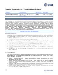
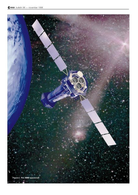
Figure 1. The XMM spacecraft
The XMM Simulator<br />
- The Technical Challenges<br />
H. Côme<br />
Simulation Section, <strong>ESA</strong> Directorate of Technical and Operational Support, ESOC,<br />
Germany<br />
M. Irvine<br />
Vega PLC, Welwyn Garden City, United Kingdom<br />
The XMM project<br />
<strong>ESA</strong>’s X-ray Multi-Mirror (XMM) observatory<br />
mission involves both a space segment and a<br />
ground segment. The former consists of the<br />
XMM satellite itself and the Ariane-5 launcher<br />
that will be used to put it into orbit. The ground<br />
segment consists of the Control Centres (MOC:<br />
Mission Operation Centre and SOC: Science<br />
Operations Centre), the ground facilities, the<br />
ground stations and the Science Survey Centre<br />
(SSC).<br />
The XMM satellite will be launched in August 1999 and a simulator has<br />
been developed to test and validate the supporting ground segment.<br />
Due to the very tight schedule and the high fidelity of the modelling<br />
required, this development effort has provided numerous unique<br />
challenges. This article details these challenges and the approaches<br />
that have been taken in meeting them, as well as the simulator’s<br />
architecture and current status.<br />
The XMM satellite (Fig. 1) is an observatory<br />
mission that will operate in the soft X-ray<br />
portion of the electromagnetic spectrum. The<br />
heart of the mission is therefore the X-ray<br />
telescope, which consists of three large mirror<br />
modules and associated focal-plane<br />
instrumentation, held together by the telescope<br />
central tube. Three scientific instruments have<br />
been selected, each of which is being<br />
developed by a separate multinational team.<br />
Each instrument team is headed by a Principal<br />
Investigator (PI) who has overall responsibility<br />
vis-a-vis <strong>ESA</strong> for the delivery of the working<br />
hardware and associated services. The three<br />
instruments that have been selected for flight<br />
are: the European Photon Imaging Camera<br />
(EPIC-MOS, EPIC-pn), the Reflection Grating<br />
Spectrometer (RGS) and the Optical Monitor<br />
(OM).<br />
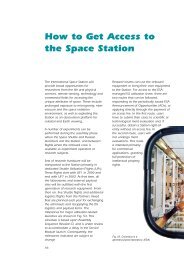
The XMM ground segment consists of the<br />
elements shown in Figure 2. The MOC will be<br />
located at ESOC in Darmstadt (D), the SOC at<br />
Villafranca near Madrid (E), and the SSC in<br />
the xmm simulator<br />
Leicester (UK). Contact with the satellite will be<br />
maintained via the <strong>ESA</strong> ground stations in<br />
Kourou (French Guiana), Perth (W. Australia)<br />
and Villafranca during the mission’s Launch and<br />
Early Orbit Phase (LEOP), and via the Kourou<br />
and Perth stations during the routine mission<br />
phase.<br />
The MOC is responsible for mission operations<br />
planning and scheduling, execution of the<br />
schedule, satellite safety and recovery from<br />
satellite anomalies, maintenance of spacecraftplatform<br />
onboard software, and instrumentanomaly<br />
recovery in real-time liaison with the<br />
SOC. The SOC, in turn, is responsible for all<br />
science operations, including observation<br />
planning and monitoring, observation-proposal<br />
handling, payload software maintenance, and<br />
data distribution to the scientific community.<br />
XMM simulator requirements<br />
An XMM MOC simulator (MOCSIM) is required<br />
to test and validate the MOC data systems. It<br />
will be used to:<br />
– test and validate the XMM Mission Control<br />
System (XMCS) and the Flight Dynamics<br />
System (FDS)<br />
– validate the XMM MOC operational<br />
database<br />
– test and validate the flight-operations<br />
procedures (both nominal and contingency)<br />
and the operations time line<br />
– validate the procedures to support System<br />
Validation Tests (SVTs) and end-to-end tests<br />
– train the Flight Operations Team.<br />
The MOC simulator is also the data source for<br />
the simulation programme, which involves the<br />
complete mission-operations team both for the<br />
LEOP and routine mission phases.<br />
Similarly, an XMM SOC simulator (SOCSIM) is<br />
required to test and validate the SOC data<br />
systems. It will be used to:
ulletin <strong>96</strong> <strong>—</strong> <strong>november</strong> <strong>1998</strong> <strong>bull</strong><br />
Figure 2. The XMM ground<br />
segment<br />
– test and validate the XMM Science Control<br />
System (XSCS)<br />
– validate the XMM SOC operational database<br />
– test and validate the instrument operation<br />
procedures (both nominal and contingency)<br />
– validate the procedure to support System<br />
Validation Tests (SVTs) and end-to-end tests<br />
– train the Science Operations Team.<br />
The SOC simulator will be the data source for<br />
the SOC simulation programme.<br />
The high-level requirements for MOCSIM are:<br />
– accurate simulation of the XMM platform<br />
– software emulation of CDMU (Control and<br />
Data Management Unit) and ACC (Attitude<br />
Control Computer) onboard processors to<br />
allow the actual onboard software to be<br />
executed at binary-code level<br />
– functional modelling of the XMM<br />
instruments, with accurate modelling of the<br />
housekeeping instrument telemetry and<br />
dummy modelling of the science telemetry<br />
– identical interface to the MOC as the actual<br />
ground-station equipment for telecommand<br />
uplinking (Telecommand Encoder: TCE) and<br />
telemetry downlinking (Telemetry Processor:<br />
TMP4)<br />
– possibility to introduce simulated failures or<br />
special effects in all platform subsystems,<br />
and to a limited extent in the instruments,<br />
during the execution of a simulation run.
The high-level requirements for SOCSIM are:<br />
– accurate functional modelling of OBDH for<br />
all related instrument functions<br />
– accurate modelling of instruments<br />
– software emulation of the various<br />
instrument-controller processors to allow<br />
actual instrument software to be executed<br />
(only one instrument is required to be<br />
emulated at a time)<br />
– accurate functional modelling of the<br />
instrument software of the processors that<br />
are not emulated<br />
– playback of science data recorded with the<br />
actual instruments<br />
– possibility to define at run-time which<br />
instrument is emulated<br />
– possibility to introduce failures or special<br />
effects in all instruments.<br />
Both MOCSIM and SOCSIM are real-time<br />
simulators, based on SIMSAT (Software<br />
Infrastructure for the Modelling of SATellite).<br />
SIMSAT is a standard ESOC infrastructure<br />
Table 1. MOCSIM and SOCSIM subsystem requirements<br />
which provides the core functionality of any<br />
simulator: real-time kernel, event scheduling,<br />
public data management, logging, commanding,<br />
graphical user interface, modelling of such<br />
ground-station equipment as telecommand<br />
encoders and telemetry processors. Both<br />
simulators also make maximum use of<br />
standard ESOC generic models and have been<br />
developed in Ada to run on DEC-Alpha<br />
workstations.<br />
The MOCSIM and SOCSIM modelling<br />
requirements are summarised in Table 1 on a<br />
subsystem-by-subsystem basis.<br />
As can be seen from Table 1, the requirements<br />
for the two simulators are different, although<br />
similarity in some of the requirements suggests<br />
that a certain amount of synergy between<br />
MOCSIM and SOCSIM could be applied.<br />
Unfortunately, only 2.5 years were available for<br />
the complete development effort, from the<br />
review of user requirements to delivery of the<br />
Subsystem MOC modelling SOC modelling<br />
Radio Frequency Accurate Fixed (TM and TC flow only)<br />
OBDH Bus Accurate Accurate<br />
CDMU Processor and Software Emulated Functional<br />
CDMU Hardware Accurate Realistic (to allow TC/TM flow)<br />
ACC Processor and Software Emulated Not required<br />
ACC Hardware Accurate Fixed<br />
Attitude Sensors (Sun Sensors, Gyros) Accurate Not required<br />
Actuators (Reaction Wheel, Thrusters) Accurate Not required<br />
Star Tracker Accurate Not required<br />
Orbit and Environment Accurate Not required<br />
Dynamics Accurate Not required<br />
Power Generation and Distribution Accurate for platform Fixed for platform,<br />
and instruments Realistic for instruments<br />
Thermal Accurate for platform Fixed for platform,<br />
and instruments Realistic for instruments<br />
RGS Accurate for HK Accurate for HK<br />
Fixed for science Accurate for science<br />
Science data file playback<br />
Emulated and functional IC<br />
EPIC-MOS Accurate for HK Accurate for HK<br />
Fixed for science Accurate for science<br />
Science data file playback<br />
Emulated and functional IC<br />
EPIC-pn Accurate for HK Accurate for HK<br />
Fixed for science Accurate for science<br />
Science data file playback<br />
Emulated and functional IC<br />
OM Accurate for HK Accurate for HK<br />
Fixed for science Accurate for science<br />
Science data file playback<br />
Emulated and functional IC<br />
EPIC Radiation Monitor Accurate for HK Accurate for HK<br />
Fixed for science Accurate for science<br />
Science data file playback<br />
TCE Realistic Realistic<br />
TMP4 Realistic Realistic<br />
the xmm simulator<br />
Note: The following terminology is used: Accurate: modelling to a declared tolerance, Realistic: modelling such that parameter trends<br />
can be observed, Fixed: no dynamic modelling is applied.
ulletin <strong>96</strong> <strong>—</strong> <strong>november</strong> <strong>1998</strong> <strong>bull</strong><br />
Table 2. XMM simulator subsystems<br />
complete system. Such a short time frame did<br />
not allow elements developed for one simulator<br />
(e.g. CDMU modelling of MOCSIM) to be<br />
reused as a baseline for the development of the<br />
other. It was therefore decided to merge the<br />
two sets of requirements and to develop a<br />
single simulator, the XMM simulator, which<br />
would meet both MOC and SOC requirements.<br />
The implementation of the XMM simulator, as<br />
summarised in Table 2, reflects the merged<br />
MOCSIM and SOCSIM User Requirements.<br />
This table indicates the level of modelling<br />
(functional or software emulation) and whether<br />
or not a generic model is used.<br />
The XMM simulator has been developed for<br />
ESOC by an industrial consortium led by Vega<br />
PLC, with Vitrociset as subcontractor. The user<br />
requirements and software requirements have<br />
been defined by <strong>ESA</strong>, with the involvement<br />
of the consortium during the software<br />
requirements phase. The architectural and<br />
detailed design phases have been performed<br />
by Vega/Vitrociset under firm fixed-price<br />
conditions, based on the XMM Simulator<br />
Software Requirements Document (SRD). The<br />
SIMSAT TCE and TMP4 ground models were<br />
developed in parallel by an industrial<br />
consortium led by TERMA, with SSL as<br />
subcontractor.<br />
Challenges and solutions<br />
The developers of the XMM simulator were<br />
confronted with two major challenges: the high<br />
fidelity of the modelling needed and the very<br />
Subsystem Modelling Generic Model<br />
Radio Frequency Functional No<br />
OBDH Bus Functional Yes<br />
CDMU Processor and Software Emulated Yes<br />
CDMU Hardware Functional Yes<br />
ACC Processor and Software Emulated Yes<br />
ACC Hardware Functional No<br />
Attitude Sensors<br />
(Sun Sensors, Gyros) Functional Yes<br />
Actuators<br />
(Reaction Wheel, Thrusters) Functional Yes<br />
Star Tracker Functional No<br />
Orbit and Environment Functional Yes<br />
Dynamics Functional Yes<br />
Power Generation and<br />
Distribution Functional Yes<br />
Thermal Functional No<br />
RGS Functional and Emulated Yes<br />
EPIC-MOS Functional and Emulated Yes<br />
EPIC-pn Functional and Emulated Yes<br />
OM Functional and Emulated Yes<br />
EPIC Radiation Monitor Functional<br />
TCE Functional Yes<br />
TMP4 Functional Yes<br />
tight schedule, which together have been the<br />
main drivers for the design and development<br />
approach adopted.<br />
The high-fidelity modelling requirement resulted<br />
in numerous technical challenges, in particular:<br />
– simulator design as close as possible to the<br />
satellite and instrument design<br />
– high number of software emulators and its<br />
impact on the computer resources<br />
– large number of possible configurations.<br />
As for any major software development, the<br />
underlying software infrastructure and<br />
development environment were also key<br />
factors. Ultimately, all of these challenges had<br />
to be addressed and solutions found which<br />
would ensure the fidelity of the modelling<br />
without drastically impacting schedule and<br />
budget.<br />
Schedule<br />
The development schedule for the XMM<br />
simulator allows just 2.5 years from User<br />
Requirements Review to delivery of the<br />
complete simulator, which is a very tight<br />
schedule indeed for such a large software<br />
project. It is made even tougher by the need to<br />
incorporate spacecraft design changes arising<br />
during the development.<br />
Incremental deliveries of the simulator have to<br />
be released at Launch–11 months (launch<br />
baselined for 2 August 1999), Launch–10<br />
months, Launch–8 months and Launch–5<br />
months to allow time for the validation of<br />
procedures and the simulation campaign.<br />
There is little flexibility within the schedule to<br />
allow for satellite design changes, major<br />
problems, etc.<br />
The XMM simulator schedule (Fig. 3) is<br />
dependant on external information being<br />
provided to the development team as<br />
Customer Furnished Items (CFIs). A set of CFIs<br />
was identified for each simulator subsystem,<br />
with due dates 2 weeks prior to the start of<br />
work on the subsystem itself. This allowed the<br />
satellite design to be followed accurately and<br />
guaranteed that the most up-to-date data<br />
(documentation, database or software) would<br />
be used.<br />
A major CFI for the simulator development<br />
is the Prime-Contractor-delivered Satellite<br />
Database (SDB). It is common to most of the<br />
work packages since it defines the<br />
telecommand and telemetry formats and<br />
contents. It is also used to generate the<br />
configuration files for the On-Board Data<br />
Handling (OBDH) model. Like the rest of the<br />
satellite design, the SDB is continually
changing, and will continue to do so up to and<br />
beyond the launch. The design approach, as<br />
presented later, has allowed the impact of<br />
these SDB changes on the design of the XMM<br />
simulator to be minimised.<br />
Following the spacecraft design<br />
Despite the fact that the XMM simulator was to<br />
be built under a firm fixed-price contract, its<br />
development had to be performed following a<br />
‘design-to-design’policy whereby the simulator<br />
had to shadow the ‘evolving design’ of the real<br />
XMM satellite. This meant no fixed baseline,<br />
which further increased the complexity of the<br />
development from both the technical and<br />
managerial viewpoints. The design baseline<br />
has been managed via a controlled set of<br />
satellite design information sources provided by<br />
ESOC as carefully selected and monitored<br />
CFIs. The Simulation Section at ESOC has<br />
been the focal point for the flow of information<br />
between the XMM Project and the XMM<br />
simulator development team. In order for the<br />
design-to-design policy to work, this<br />
information flow had to be maintained<br />
throughout the simulator and XMM satellite<br />
development efforts.<br />
Payload modelling<br />
The accurate modelling required for the XMM<br />
payload is a good example of the challenges<br />
implied by the above policy. The very complex<br />
XMM instruments are being developed by<br />
scientific institutes, under extreme time<br />
pressure. Consequently, immediate access to<br />
design information has not always been<br />
possible. The simulator development team has<br />
therefore had to make assumptions concerning<br />
the designs of the different instruments.<br />
Because of the latter’s uniqueness, these<br />
assumptions have had to be carefully validated<br />
to ensure that the simulator design remained in<br />
line with that of the instruments. As it was not<br />
possible to overly divert the instrument<br />
Principal Investigators from their own critical<br />
development work, special Workshops were<br />
organised for each instrument, bringing<br />
together the scientists, XMM project staff and<br />
the simulator development team.<br />
Science data files<br />
The baseline for the XMM simulator was to play<br />
back science data recorded from the actual<br />
instruments. Early in 1997, however, it was<br />
recognised that science data covering all<br />
operational modes would not be available from<br />
ground testing. An alternative source of data<br />
had therefore to be identified. The Science<br />
Simulator (SciSIM) developed by <strong>ESA</strong> Space<br />
Science Department seemed a good<br />
the xmm simulator<br />
Figure 3. Schedule for the<br />
XMM simulator’s<br />
development
ulletin <strong>96</strong> <strong>—</strong> <strong>november</strong> <strong>1998</strong> <strong>bull</strong><br />
Figure 4. Instrument<br />
configuration selection<br />
candidate, although the data (Observation Data<br />
File - ODF) that it generated would need to be<br />
modified for compatibility with the architecture<br />
and design baseline foreseen for the XMM<br />
simulator. An offline utility (XMM Science Data<br />
File Conversion Utility) was developed to<br />
convert ODF into Pre-IC data files usable by the<br />
XMM simulator. This task had to be performed<br />
in parallel with the development of the XMM<br />
simulator, and was defined to fit in with the<br />
various XMM simulator deliveries. The<br />
XMM simulator development team actively<br />
participated in the review and acceptance of the<br />
Science Data File conversion utility.<br />
Emulation and computer resources<br />
The XMM simulator has to cope with three<br />
software emulations of an MA31750 processor<br />
implementing the MIL1750A instruction-set<br />
standard. Software emulations had already<br />
been used in previous ESOC simulators, but<br />
XMM was the first simulator to require three<br />
emulators running in parallel (CDMU, ACC and<br />
one of the instruments). In any simulator, the<br />
most demanding computer resource by far is<br />
the emulator. Early indications based on<br />
previous projects showed that running three<br />
emulators could be feasible on a high-end DEC<br />
Alpha mono-processor workstation. Since there<br />
was a small risk involved with the approach, a<br />
detailed performance analysis was made during<br />
the architectural design phase.<br />
That performance analysis revealed that the<br />
MA31750 processor used by XMM was<br />
significantly more powerful and therefore more<br />
demanding in terms of computer resources<br />
than the 1750 and 31750 processors used on<br />
previous satellites. Computer resource<br />
projections were made for the different XMM<br />
onboard software items to be emulated, taking<br />
into account their characteristics (processors,<br />
clock speed, wait states), to obtain the<br />
projected CPU requirement of the XMM<br />
simulator. This showed that running three<br />
emulators would be extremely marginal on a<br />
mono-processor workstation. All of ESOC’s<br />
earlier simulators had been targeted to monoprocessor<br />
workstations and SIMSAT had never<br />
been used or tested in a multi-processor/multithread<br />
environment. An analysis carried out to<br />
identify potential problems, and to validate the<br />
core of the simulator architecture, concluded<br />
that a multi-thread/multi-processor architecture<br />
was indeed feasible and would not require any<br />
modifications to SIMSAT. The choice was<br />
therefore made to adopt this architecture and<br />
to run the XMM simulator on a DEC Alpha dualprocessor<br />
workstation (DEC AXP 1200).<br />
Simulator configurations<br />
The simulator configurations define whether a<br />
functional or an emulated model is to be<br />
configured for each of the instruments. The<br />
XMM simulator has seven possible<br />
configurations, which can be conveniently<br />
selected using the SIMSAT MMI (man/machine<br />
interface). A configuration ‘switch’ in the<br />
instrument models is then used to select either<br />
the functional or emulated processor model<br />
(Fig. 4).<br />
New ground and generic models<br />
The XMM simulator is the first user of the new<br />
SIMSAT TCE and TMP4 ground models<br />
developed in parallel with the simulator. These<br />
are the first SIMSAT ground models to<br />
implement the <strong>ESA</strong> telemetry and telecommand<br />
packet standard. Due to their size and<br />
complexity, their delivery date was close to that<br />
of the XMM simulator, leaving very little time for<br />
integration and end-to-end testing. Fortunately,<br />
with SIMSAT the interface between spacecraft<br />
models and ground models is standardised.<br />
Moreover, the XMM development team was<br />
involved in the requirements reviews for these<br />
models, which helped to avoid incorrect<br />
assumptions being made on either side.<br />
Architecture of the XMM simulator<br />
The general architecture of the XMM simulator<br />
is shown in Figures 5 and 6. Its main<br />
characteristics are as follows:<br />
– The breakdown into simulator subsystems<br />
reflects the satellite subsystems, for example<br />
RF, OBDH, power, thermal, etc. Interfaces<br />
between subsystems in the simulator then<br />
become identifiable against the actual<br />
satellite design, interface documents, etc.<br />
– The interfaces between subsystems are<br />
minimised to aid design and ultimately<br />
simplify integration.<br />
– Each subsystem can be viewed as a<br />
‘module’with an OBDH bus connection<br />
point, power network connection points,<br />
and thermal connection points. This is an
the xmm simulator<br />
Figure 5. XMM simulator<br />
interfaces<br />
Figure 6. XMM simulator<br />
architecture
ulletin <strong>96</strong> <strong>—</strong> <strong>november</strong> <strong>1998</strong> <strong>bull</strong><br />
important feature since it allows for<br />
incremental deliveries of the simulator, each<br />
delivery adding new subsystems and<br />
functionality. Integrating a new subsystem<br />
into the simulator within the defined<br />
architecture ‘only’ involves connecting it to<br />
the OBDH bus, power network and thermal<br />
network.<br />
– The instrument models are configurable as<br />
emulated or functional models. For<br />
commonality and efficiency reasons, both<br />
emulated and functional models use the<br />
same memory models, and access the<br />
hardware models through the same I/O<br />
interface models.<br />
– The OBDH Remote Terminal Unit (RTU)<br />
model is initialised from files auto-generated<br />
from the Satellite Database (SDB). This file<br />
sets up the RTU commands, acquisitions<br />
and calibration curves used during<br />
analogue-to-digital conversions. This is an<br />
important feature since it minimises the<br />
impact of SDB changes on the OBDH models.<br />
Most changes in the contents of the SDB<br />
with respect to OBDH bus traffic only require<br />
the re-generation of the configuration files<br />
and then start up of the simulator. This has<br />
obvious time benefits not only during simulator<br />
development, but also for simulator maintenance.<br />
– The XMM simulator has a telemetry decoder<br />
facility, which processes telemetry packets<br />
produced by the CDMU system. Analogue<br />
telemetry parameters are displayed in both<br />
engineering and raw format. The telemetrydecoder<br />
facility allows simulator operation<br />
without the XMM Control System, which is<br />
extremely useful during the simulator’s<br />
system and acceptance testing. Like the<br />
OBDH RTU model, it uses configuration files<br />
auto-generated from the SDB, with the<br />
same benefits.<br />
Current status<br />
The first XMM simulator delivery was made at<br />
the end of June <strong>1998</strong>, and the second at the<br />
end of August. The latter, which at the time of<br />
writing is still under acceptance testing,<br />
consists of a full platform model, including<br />
emulation of both the CDMU and ACC<br />
software. It currently runs on the target<br />
workstation in a mono-processor configuration.<br />
The third delivery, which will add one<br />
instrument, namely RGS, and implement the<br />
multi-processor architecture, is under final<br />
coding and testing and will be released at the<br />
end of September. The complete simulator will<br />
be released at the end of November <strong>1998</strong>. A<br />
final delivery, incorporating corrections to any<br />
errors found during the user acceptance of the<br />
simulator, will take place at the end of February<br />
1999.<br />
Conclusion<br />
The XMM simulator is an ambitious project due<br />
to the combination of the high fidelity of the<br />
modelling required and the very tight<br />
implementation schedule. To ensure that its<br />
design would closely mirror that of the satellite,<br />
the Customer Furnished Items that have been<br />
used in the simulator’s development have been<br />
selected and monitored with considerable care.<br />
The simulator’s architecture has been designed<br />
to take full advantage of the DEC Alpha multiprocessor<br />
workstation in order to support the<br />
high number of configurations required.<br />
Maximum use was made of the ESOC<br />
infrastructure and expertise in order to cope<br />
with the strict schedule and budget constraints,<br />
and in seeking appropriate solutions to each of<br />
the challenges that would satisfy all parties. In<br />
the event, the very good co-operation between<br />
all parties involved - the XMM Project, Science<br />
and Operations Teams, the ESOC Simulation<br />
Section, and XMM Simulator Development<br />
Team - has been one of the key elements in this<br />
development project’s success. r