Miniaturisation for chemistry, physics, biology, & bioengineering
Miniaturisation for chemistry, physics, biology, & bioengineering
Miniaturisation for chemistry, physics, biology, & bioengineering

You also want an ePaper? Increase the reach of your titles
YUMPU automatically turns print PDFs into web optimized ePapers that Google loves.
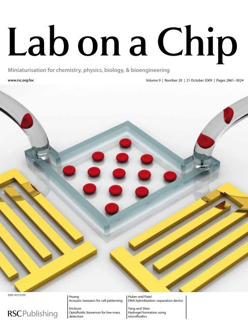
<strong>Miniaturisation</strong> <strong>for</strong> <strong>chemistry</strong>, <strong>physics</strong>, <strong>biology</strong>, & <strong>bioengineering</strong><br />
www.rsc.org/loc Volume 9 | Number 20 | 21 October 2009 | Pages 2861–3024<br />
ISSN 1473-0197<br />
Huang<br />
Acoustic tweezers <strong>for</strong> cell patterning<br />
Erickson<br />
Optofluidic biosensor <strong>for</strong> low mass<br />
detection<br />
Huber and Patel<br />
DNA hybridization–separation device<br />
Yang and Shen<br />
Hydrogel <strong>for</strong>mation using<br />
microfluidics
PAPER www.rsc.org/loc | Lab on a Chip<br />
Acoustic tweezers: patterning cells and microparticles using standing surface<br />
acoustic waves (SSAW)†<br />
Jinjie Shi, a Daniel Ahmed, a Xiaole Mao, ab Sz-Chin Steven Lin, a Aitan Lawit a and Tony Jun Huang* ab<br />
Received 29th May 2009, Accepted 22nd July 2009<br />
First published as an Advance Article on the web 5th August 2009<br />
DOI: 10.1039/b910595f<br />
Here we present an active patterning technique named ‘‘acoustic tweezers’’ that utilizes standing surface<br />
acoustic wave (SSAW) to manipulate and pattern cells and microparticles. This technique is capable of<br />
patterning cells and microparticles regardless of shape, size, charge or polarity. Its power intensity,<br />
approximately 5 10 5 times lower than that of optical tweezers, compares favorably with those of<br />
other active patterning methods. Flow cytometry studies have revealed it to be non-invasive. The<br />
a<strong>for</strong>ementioned advantages, along with this technique’s simple design and ability to be miniaturized,<br />
render the ‘‘acoustic tweezers’’ technique a promising tool <strong>for</strong> various applications in <strong>biology</strong>,<br />
<strong>chemistry</strong>, engineering, and materials science.<br />
Introduction<br />
The ability to arrange cells and microparticles into desired<br />
patterns is critical <strong>for</strong> numerous biological studies and applications<br />
such as microarrays, 1,2 tissue engineering, 3,4 and regenerative<br />
medicine. 5,6 Researchers have developed a variety of<br />
patterning techniques such as microcontact printing, 7–9 optical<br />
tweezers, 10,11 optoelectronic tweezers, 12,13 magnetic tweezers, 14–16<br />
electro-/dielectro-phoresis, 17–21 evanescent waves/plasmonics, 22,23<br />
hydrodynamic flows, 24–32 and bulk acoustic wave-based acoustophoresis.<br />
33–37<br />
The invention of optical tweezers 10,11 and developments in<br />
optofluidics 38–41 have spurned a new plat<strong>for</strong>m <strong>for</strong> manipulating<br />
and patterning micro/nanoscale objects with unprecedented<br />
precision. Chiou et al. demonstrated optoelectronic tweezers that<br />
featured not only the high precision of optical tweezers, but also<br />
achieved high throughput and low power consumption, with<br />
a power intensity approximately 1 10 5 times less than that of<br />
optical tweezers. 12 Most recently, Yang et al. demonstrated<br />
trapping and transporting dielectric nanoparticles as small as<br />
75 nm using sub-wavelength slot waveguides. 42 Despite the<br />
impressive per<strong>for</strong>mance of such optics-based patterning and<br />
manipulating techniques, they require bulky, complicated optical<br />
setups, which are difficult to miniaturize. Techniques based on<br />
magnetic/electrical fields (such as magnetic tweezers, electrophoresis,<br />
and dielectrophoresis) 14–21 could serve as alternative<br />
solutions. These techniques are amenable to device miniaturization,<br />
but they have limited versatility. For example, magnetic<br />
tweezers require targets to be pre-labeled with magnetic materials.<br />
The recently developed bulk acoustic wave (BAW)-based<br />
a Department of Engineering Science and Mechanics, The Pennsylvania<br />
State University, University Park, PA, 16802, USA. E-mail: junhuang@<br />
psu.edu; Fax: +1 814-865-9974; Tel: +81 14-863-4209<br />
b Department of Bioengineering, The Pennsylvania State University,<br />
University Park, Pennsylvania, 16802, USA<br />
† Electronic supplementary in<strong>for</strong>mation (ESI) available: Including device<br />
fabrication, simulation of standing surface acoustic waves, flow<br />
cytometry measurements, qualitative <strong>for</strong>ce analysis and ID and 2D<br />
patterning of fluorescent microparticles. See DOI: 10.1039/b910595f<br />
acoustophoresis have shown promise in manipulating macro/<br />
micro particles regardless of their optical or electrical properties.<br />
33–37 However, it is challenging to implement these BAWbased<br />
techniques with the existing fast-prototyping methods,<br />
such as soft lithography, that are widely used in microfluidics.<br />
Due to the limitations of the existing techniques, researchers are<br />
still searching <strong>for</strong> cell-patterning techniques that simultaneously<br />
meet specifications <strong>for</strong> miniaturization, versatility, throughput,<br />
speed, and power consumption.<br />
A surface acoustic wave (SAW) is a sound wave that propagates<br />
along the surface of an elastic material. 43 When SAW<br />
propagates, most of its energy is confined within one to two<br />
wavelengths normal to the surface of the substrate. 43 This energyconfining<br />
characteristic makes SAW an energy-efficient tool <strong>for</strong><br />
manipulating particles and biomaterials. Furthermore, SAWbased<br />
techniques are free of contamination, only introducing<br />
low-power mechanical vibrations to the suspension. Recently,<br />
researchers have demonstrated SAW-based mixing, 44 pumping, 45<br />
concentration, 46 and particle focusing. 47 In this paper, we reveal<br />
an ‘‘acoustic tweezers’’ technique, in which microparticles and<br />
cells can be effectively patterned using standing surface acoustic<br />
waves (SSAW). This technique is versatile, non-invasive, and<br />
amenable to miniaturization, and its power consumption<br />
and speed compare favorably to those of existing active cellpatterning<br />
techniques.<br />
Working mechanism<br />
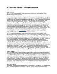
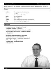
Fig. 1 illustrates the working principle of the ‘‘acoustic tweezers.’’<br />
The device consists of a polydimethylsiloxane (PDMS) microfluidic<br />
channel and a pair of interdigital transducers (IDTs)<br />
deposited on a piezoelectric substrate in a parallel (Fig. 1a) or<br />
orthogonal (Fig. 1b) arrangement. A solution of microparticles<br />
or cells is infused into the microchannel by a pressure-driven<br />
flow. Once the distribution of particles or cells stabilizes in the<br />
channel, a radio frequency (RF) signal is applied to both IDTs to<br />
generate two series of identical SAWs propagating either in the<br />
opposite (Fig. 1a) or orthogonal (Fig. 1b) direction. The interference<br />
of these two series of SAWs <strong>for</strong>ms a SSAW, as well as<br />
2890 | Lab Chip, 2009, 9, 2890–2895 This journal is ª The Royal Society of Chemistry 2009
Fig. 1 Schematic of the SSAW-based patterning devices. (a) 1D<br />
patterning using two parallel IDTs. (b) 2D patterning using two<br />
orthogonal IDTs (the angle between the IDTs can be changed to achieve<br />
different patterns).<br />
a periodic distribution of pressure nodes (with minimum pressure<br />
amplitude) and antinodes (with maximum pressure amplitude)<br />
on the substrate—the pressure distribution can be visualized<br />
from the simulated results (Fig. S2b and d, see detailed description<br />
in the ESI†). 48 When the SSAW encounters the liquid<br />
medium inside the channel, longitudinal-mode leakage waves are<br />
generated, causing pressure fluctuations in the medium. 44–47,49<br />
These fluctuations lead to acoustic radiation <strong>for</strong>ces that act on<br />
the suspended particles, moving them to the pressure nodes or<br />
antinodes in the SSAW field. 35,47,49 The primary acoustic <strong>for</strong>ce<br />
exerted on an object in a SSAW field can be expressed as 49<br />
Fr ¼ (pp 2 0Vcbw/2l)$f(b,r)$sin(2kx) (1)<br />
fðb; rÞ ¼ 5rc 2rw bc (2)<br />
2rc þ rw bw where p0, l, Vc are the acoustic pressure, wavelength, volume of<br />
the object, respectively; and rc, rw, bc, bw represent the density of<br />
the object, density of the medium, compressibility of the object,<br />
and compressibility of the medium, respectively. f determines the<br />
balanced positions of the objects: if f > 0, the objects will<br />
aggregate at pressure nodes, and vice versa. In a one-dimensional<br />
(1D) SSAW field, the pressure nodes (or antinodes) are aligned in<br />
multiple lines, which are parallel to the wave fronts (Fig. S2b,<br />
ESI†), resulting in a 1D pattern of particles along these lines<br />
(Fig. 1a). In a two-dimensional (2D) SSAW field, instead of<br />
<strong>for</strong>ming parallel lines, pressure nodes (or antinodes) <strong>for</strong>m<br />
orthogonal 2D arrays (Fig. S2d, ESI†). Particles move towards<br />
nearby pressure nodes (or antinodes), <strong>for</strong>ming 2D patterned<br />
aggregations (Fig. 1b).<br />
Methods<br />
Device fabrication and experimental procedure<br />
There are three steps involved in the device fabrication (see<br />
Fig. S1 in the ESI†). Firstly, a thin layer of metal (Ti/Au, 50 A ˚ /<br />
800 A ˚ ) was deposited on a photoresist-patterned lithium niobate<br />
substrate, followed by a lift-off process to <strong>for</strong>m the IDTs.<br />
Secondly, polydimethylsiloxane (PDMS) microchannels were<br />
fabricated using standard soft lithography and mold-replica<br />
techniques. A pre-patterned silicon substrate was deep-etched to<br />
serve as the mold <strong>for</strong> PDMS channel fabrication. At last, the<br />
PDMS microchannel was aligned and bonded with the lithium<br />
niobate substrate, obtaining the desired device (see more details<br />
in the ESI†).<br />
System setup<br />
The SSAW-based patterning device was mounted on the stage of<br />
an inverted microscope (Nikon TE2000U), and solutions of<br />
fluorescent beads, bovine red blood cells (bRBC), and E. coli cells<br />
were injected into the device through a syringe pump (KDS210,<br />
Kd Scientific). An AC signal generated by an RF signal generator<br />
(Agilent E4422B) was split into two coherent signals, which<br />
were subsequently connected to the IDTs to generate SSAW.<br />
A CCD camera (CoolSNAP HQ2, Photometrics, Tucson, AZ)<br />
was connected to the microscope to capture the patterning<br />
processes. The power of the applied SAW was 200 mW (working<br />
area of 1 cm 2 ) in all of our experiments.<br />
Sample preparation<br />
Fluorescent (Dragon Green) polystyrene beads (11 760 000<br />
beads mL 1 , 1.9 mm in diameter, Bangs Laboratories), bRBCs<br />
( 6 mm in diameter, Innovative Research, Inc.), and E. coli cells<br />
( 800 nm in diameter, 1–3 mm in length) dyed with green<br />
fluorescence proteins (GFP) encoded plasmids were used in the<br />
patterning experiments. After the induced GFP expression,<br />
E. coli colonies were selected and re-suspended in PBS buffer to<br />
desired concentrations. Freshly-prepared E. coli cells, grown to<br />
mid-logarithmic phase in LB media, were divided into four parts:<br />
(a) pre-treated cells cultured <strong>for</strong> 12 h (Positive Control 1), (b)<br />
cells that flow through the microchannel without applying<br />
SSAW (Positive Control 2), (c) cells that experienced the SSAW<br />
patterning process in the microfluidic system (SSAW Sample),<br />
and (d) cells that were heated at 70 C <strong>for</strong> 30 min (Negative<br />
Control). After the treatment, each group of cell culture was<br />
diluted in PBS buffer at a 1 : 100 ratio, and a 2 mL stock solution<br />
of DiBAC 4(3) (Molecular probes, USA) was added to a 1 ml<br />
diluted cell suspension, resulting in a dye concentration of<br />
5 mgmL 1 . The cells were then stained <strong>for</strong> 30 min be<strong>for</strong>e the flow<br />
cytometry measurement. The flow cytometry test was per<strong>for</strong>med<br />
on a Beckman-Coulter XL-MCL flow cytometer using a bluelight<br />
(488 nm) excitation source. For each test, 2 10 4 cells were<br />
counted.<br />
This journal is ª The Royal Society of Chemistry 2009 Lab Chip, 2009, 9, 2890–2895 | 2891
Results and discussion<br />
Patterning of micro polystyrene beads<br />
We first examined the ‘‘acoustic tweezers’’ technique in<br />
patterning fluorescent (Dragon Green) polystyrene beads of<br />
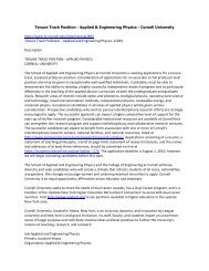
mean diameter 1.9 mm. Fig. 2 shows optical images of the 1D and<br />
2D patterning devices. When the SSAW was applied, the beads<br />
aggregated at the pressure nodes, <strong>for</strong>ming 1D and 2D patterns.<br />
The periods of the patterns were measured to be approximately<br />
50 mm (1D pattern in Fig. 2c) and 140 mm (2D pattern in Fig. 2d).<br />
The experimentally measured data matched well with the simulated<br />
results (Fig. S2 b and d, ESI†), which predicted that the<br />
period of the 1D pattern would be half of the SAW working<br />
wavelength<br />
p ffiffi<br />
(50 mm) and that the period of the 2D pattern would<br />
be 2=2<br />
times the SAW working wavelength (141 mm). The size<br />
of the bead aggregations at the pressure nodes (Fig. 2c and 2d)<br />
can be tuned by altering the applied power. Higher power leads<br />
to larger acoustic radiation <strong>for</strong>ces, resulting in close-packed bead<br />
aggregations.<br />
Patterning of cells<br />
We further proved that the ‘‘acoustic tweezers’’ technique can<br />
readily be used to pattern different types of cells—bRBC in<br />
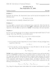
Fig. 3a and E. coli cells in Fig. 3b. These results verify the<br />
versatility of our technique as the two groups of cells differ<br />
significantly in both shape (spherical bRBC vs. rod-shaped<br />
E. coli) and size ( 6 mm vs. 1 mm). Furthermore, the patterning<br />
per<strong>for</strong>mance is independent of the particles’ electrical/magnetic/<br />
optical properties. One concern about this technique is that the<br />
mechanical <strong>for</strong>ces generated by the acoustic waves may potentially<br />
damage cells during the patterning process. For example,<br />
BAW has been widely used in ultrasonic imaging, cell sonoporation,<br />
and ultrasound-enhanced drug delivery. 50–52 In comparison<br />
to these BAW-based techniques, which operate at larger<br />
power intensities (2000–6000 W m 2 ) <strong>for</strong> tens of minutes or even<br />
hours without significantly reducing cell viability, our ‘‘acoustic<br />
tweezers’’ technique used nominal power intensity and took only<br />
seconds to drive cells to pressure nodes. Damages caused by<br />
acoustic <strong>for</strong>ces during this period should be trivial. Once the cells<br />
Fig. 2 Patterning of fluorescent polystyrene microbeads. Optical images of the ‘‘acoustic tweezers’’ devices used in (a) 1D and (b) 2D patterning<br />
experiments, respectively. (c) Distribution of the microbeads be<strong>for</strong>e and after the 1D patterning process. The microchannel (width ¼ 150 mm and depth ¼<br />
80 mm) covered three lines of pressure nodes of the generated SSAW. The wavelength of SAW was 100 mm (see Supplementary Video 1, ESI†). (d),<br />
Distribution of the microbeads be<strong>for</strong>e and after the 2D patterning process. The SAW wavelength was 200 mm.<br />
2892 | Lab Chip, 2009, 9, 2890–2895 This journal is ª The Royal Society of Chemistry 2009
Fig. 3 SSAW-based cell patterning. (a) Patterning of bRBC. The wavelength of the applied SAW was 100 mm. (b) Patterning of E. coli cells pretreated<br />
with Dragon Green fluorescent dyes. The wavelength of the applied SAW was 300 mm (see Supplementary Video 2, ESI†). I IV shows the dynamic<br />
process of E. coli cells aggregate at a pressure node. (c–f), Flow cytometric histograms (DiBAC4(3) fluorescent light intensity (FI) vs. <strong>for</strong>ward scattering<br />
(FS)) <strong>for</strong> different cell types. (c) E. coli cells cultured <strong>for</strong> 12 h (Positive Control 1); (d) E. coli cells that passed through a microchannel without applying<br />
SSAW (Positive Control 2); (e) E. coli cells that experienced the SSAW-based patterning process in a microchannel (SSAW Sample); and (f) E. coli cells<br />
heated at 70 C <strong>for</strong> 30 min (Negative Control).<br />
reached the pressure nodes, the acoustic pressures, and thus<br />
acoustic <strong>for</strong>ces applied to the cells, were nearly zero; cells were<br />
steadily patterned in the ‘‘wells’’ defined by the pressure gradients<br />
around the pressure nodes. At the same time, the pressure<br />
oscillations inside the patterned cells (at pressure nodes) are also<br />
nearly zero, minimizing the heat generation. These characteristics<br />
suggest that the ‘‘acoustic tweezers’’ technique would be noninvasive<br />
to cells.<br />
In order to confirm the non-invasive nature of our technique,<br />
we studied the integrity of the cell membranes be<strong>for</strong>e and after<br />
the patterning process. We used a membrane-potential-sensitive<br />
dye, DiBAC 4(3) (bis-(1,3-dibarbituric acid)-trimethine oxanol),<br />
as an indicator <strong>for</strong> cell viability. DiBAC 4(3) is an anionic lipophilic<br />
fluorescent dye which is found mainly in the outer<br />
cytoplasmic membranes of intact cells. 47 It enters the cell body<br />
and accumulates in the cytoplasm when the cell membrane is<br />
damaged. Thus, the amount of dye accumulation, which is<br />
indicated by the average fluorescent intensity (FI), can be used to<br />
quantify the degree of membrane disruption caused by our<br />
technique. We per<strong>for</strong>med flow cytometry experiments to quantitatively<br />
analyze the viability of cells, in which FI and the<br />
<strong>for</strong>ward scattering (FS) signals represented the cell viability and<br />
size distribution, respectively. 53 As shown in Fig. 3c–e, the E. coli<br />
cells after the SSAW patterning process (average FI ¼ 0.536;<br />
Fig. 3e) exhibited distribution peaks almost identical to those of<br />
the cells prior to the pattering process (positive controls of<br />
average FI ¼ 0.530–0.536; Fig. 3c and 3d). On the other hand,<br />
the cells incubated at 70 C <strong>for</strong> 30 min (negative control; Fig. 3f)<br />
exhibited a much higher FI (2.2), implying that the cell<br />
membranes were severely damaged. These results (as detailed in<br />
Supplementary Table 1, ESI†) confirm that our SSAW-based<br />
‘‘acoustic tweezers’’ technique is non-invasive.<br />
Quantitative <strong>for</strong>ce analysis<br />
The behavior of cells or other objects in a SSAW field can be<br />
predicted via theoretical <strong>for</strong>ce analyses. The primary <strong>for</strong>ces<br />
involved in the SSAW patterning process are as follows: (1)<br />
acoustic radiation <strong>for</strong>ces; 35,44–47,49 (2) viscous <strong>for</strong>ces; (3) buoyant<br />
<strong>for</strong>ces; and (4) gravity. Among these <strong>for</strong>ces, buoyant <strong>for</strong>ces are<br />
typically balanced by gravitational <strong>for</strong>ces as they are of similar<br />
magnitudes and in opposite directions. Fig. 4a shows the<br />
dependence of these <strong>for</strong>ces on particle size. It reveals that when<br />
the diameters of the particles are >1 mm, acoustic <strong>for</strong>ces dominate<br />
under the applied power intensity. Fig. 4b shows that when<br />
the SAW wavelength is smaller than 100 mm, the acoustic <strong>for</strong>ces<br />
acting upon the targets (polystyrene beads with diameter of<br />
1.9 mm, bRBC, and E. coli cells) are significantly stronger than<br />
the viscous <strong>for</strong>ces. In this study, all the particles were trapped at<br />
the pressure node, where the acoustic <strong>for</strong>ce was minimal and<br />
particles were immobilized due to the <strong>for</strong>ce gradient around the<br />
pressure node. Fig. 4c shows the acoustic <strong>for</strong>ce distribution<br />
within a half wavelength region centered at a pressure node. The<br />
results show that the acoustic <strong>for</strong>ces change sinusoidally and<br />
point to the pressure node, <strong>for</strong>ming a trapping well (inset of<br />
Fig. 4c). To release a particle from the trapping well, one must<br />
This journal is ª The Royal Society of Chemistry 2009 Lab Chip, 2009, 9, 2890–2895 | 2893
Fig. 4 Theoretical analyses. (a) Size dependence of acoustic <strong>for</strong>ce (AF), viscous <strong>for</strong>ce (VF), buoyant <strong>for</strong>ce, and gravitational <strong>for</strong>ce. (b), Dependence of<br />
AF and VF on the working wavelength <strong>for</strong> different objects. (c) The distribution of trapping <strong>for</strong>ce around a pressure node (PN). The <strong>for</strong>ces on beads and<br />
E. coli are magnified 10 times <strong>for</strong> clear visualization. The inset indicates the <strong>for</strong>ce vectors and equal <strong>for</strong>ce contours around the PN. The SAW wavelength<br />
was 100 mm. (d) Calculated and experimental patterning time. The SAW intensity was 2000 W m 2 , and the particles speed was 1 mm s 1 in VF<br />
calculation.<br />
overcome the maximum acoustic <strong>for</strong>ce in the field (25 pN <strong>for</strong><br />
bRBC). By increasing the operation power or reducing the SAW<br />
working wavelength, one can further increase the stiffness of the<br />
trapping well built by the acoustic <strong>for</strong>ces gradient around<br />
the pressure nodes or antinodes, making it possible to manipulate<br />
and pattern nanoscale particles. 35,42,44–47,49 In addition, our<br />
experimental and calculated results (Fig. 4d) show that the<br />
process <strong>for</strong> patterning polystyrene beads and bRBC takes less<br />
than 3 s, a speed faster than those of the previously reported<br />
studies. 12,17,18,25 Detailed description of the theoretical model<br />
used in Fig. 4 can be found in the ESI.†<br />
In conclusion, we have demonstrated a SSAW-based ‘‘acoustic<br />
tweezers’’ technique that enables one to actively pattern cells and<br />
microparticles. This technique does not require pre-treatments<br />
on the substrates or cells/microparticles. It is applicable to<br />
virtually any type of cell/microparticle regardless of size, shape,<br />
or electrical/magnetic/optical properties. We verified this versatility<br />
by patterning polystyrene beads, bRBC, and E. coli cells.<br />
The required power intensity of acoustic tweezers (2000 W m 2 )<br />
is 5 10 5 times lower than that of optical tweezers (10 9 Wm 2 )<br />
and compares favorably to those of other patterning<br />
methods. 12,23 Such a low power intensity also contributes to the<br />
technique’s non-invasive nature, as confirmed by our cell<br />
viability studies. With its advantages in versatility, miniaturization,<br />
power consumption, speed, and technical simplicity, our<br />
‘‘acoustic tweezers’’ technique is a powerful tool <strong>for</strong> applications<br />
such as tissue engineering, microarray, cell studies, and drug<br />
screening and discovery.<br />
Acknowledgements<br />
We thank Dr Bernhard R. Tittmann, Dr Kenji Uchino, Subash<br />
Jayaraman and Seyit Ural <strong>for</strong> help with equipments, and Yanjun<br />
Liu and Thomas R. Walker <strong>for</strong> helpful discussion. This research<br />
was supported by National Science Foundation (ECCS-0824183,<br />
ECCS-0801922, and ECCS-0609128) and the Penn State Center<br />
<strong>for</strong> Nanoscale Science (MRSEC). Components of this work were<br />
conducted at the Penn State node of the NSF-funded National<br />
Nanotechnology Infrastructure Network.<br />
References<br />
1 C. J. Flaim, S. Chien and S. N. Bhatia, Nat. Methods, 2005, 2,<br />
119–125.<br />
2 D. B. Wheeler, A. E. Carpenter and D. M. Sabatini, Nat. Genet., 2005,<br />
37, S25–S30.<br />
3 M. M. Stevens, M. Mayer, D. G. Anderson, D. B. Weibel,<br />
G. M. Whitesides and R. Langer, Biomaterials, 2005, 26, 7636–7641.<br />
4 A. Tourovskaia, X. Figueroa-Masot and A. Folch, Lab Chip, 2005, 5,<br />
14–19.<br />
5 C. Smith, Nature, 2007, 446, 219–222.<br />
6 S. R. Khetani and S. N. Bhatia, Nat. Biotechnol., 2007, 26, 120–126.<br />
7 A. Hernard and et al, Langmuir, 1998, 14, 2225–2229.<br />
8 E. S. Douglas, R. A. Chandra, C. R. Bertozzi, R. A. Mathies and<br />
M. B. Francis, Lab Chip, 2007, 7, 1442–1448.<br />
2894 | Lab Chip, 2009, 9, 2890–2895 This journal is ª The Royal Society of Chemistry 2009
9 S. Pernagallo, J. J. Diaz-Mochon and M. Bradley, Lab Chip, 2009, 9,<br />
397–403.<br />
10 A. Ashkin, J. M. Dziedzic and T. Yamane, Nature, 1987, 330,<br />
769–771.<br />
11 D. G. Grier, Nature, 2003, 424, 810–816.<br />
12 P. Y. Chiou, A. T. Ohta and M. C. Wu, Nature, 2005, 436, 370–372.<br />
13 H. Hwang and J.-K. Park, Lab Chip, 2009, 9, 199–206.<br />
14 H. Lee, A. M. Purdon and R. M. Westervelt, Appl. Phys. Lett., 2004,<br />
85, 1063–1065.<br />
15 K. Ino, M. Okochi, N. Konishi, M. Nakatochi, R. Imai, M. Shikida,<br />
A. Ito and H. Honda, Lab Chip, 2008, 8, 134–142.<br />
16 H. Lee, Y. Liu, D. Ham and R. M. Westervelt, Lab Chip, 2007, 7,<br />
331–337.<br />
17 N. Mittal, A. Rosenthal and J. Voldman, Lab Chip, 2007, 7, 1146–<br />
1153.<br />
18 C.-T. Ho, R.-Z. Lin, W.-Y. Chang, H.-Y. Chang and C.-H. Liu, Lab<br />
Chip, 2006, 6, 724–734.<br />
19 R. S. Thomas, H. Morgan and N. G. Green, Lab Chip, 2009, 9,<br />
1534–1540.<br />
20 T.-H. Wang, Y. Peng, C. Zhang, P. K. Wong and C.-M. Ho, J. Am.<br />
Chem. Soc., 2005, 127, 5354–5359.<br />
21 M. Abdelgawad, M. W. L. Watson and A. R. Wheeler, Lab Chip,<br />
2009, 9, 1046–1051.<br />
22 S. Kawata and T. Sugiura, Opt. Lett., 1992, 17, 772–774.<br />
23 M. Righini, A. S. Zelenina, C. Girard and R. Quidant, Nat. Phys.,<br />
2007, 3, 477–480.<br />
24 C.-H. Hsu, D. Di Carlo, C. Chen, D. Irimia and M. Toner, Lab Chip,<br />
2008, 8, 2128–2134.<br />
25 D. Di Carlo, L. Y. Wu and L. P. Lee, Lab Chip, 2006, 6, 1445–1449.<br />
26 M. Deutsch, A. Deutsch, O. Shirihai, I. Hurevich, E. Afrimzon,<br />
Y. Shafran and N. Zurgil, Lab Chip, 2006, 6, 995–1000.<br />
27 A. Manbachi, S. Shrivastava, M. Cioffi, B. G. Chung, M. Moretti,<br />
U. Demirci, M. Yliperttula and A. Khademhosseini, Lab Chip,<br />
2008, 8, 747–754.<br />
28 M. C. Park, J. Y. Hur, K. W. Kwon, S.-H. Park and K. Y. Suh, Lab<br />
Chip, 2006, 6, 988–994.<br />
29 A. Azioune, M. Storch, M. Bornens, M. Thery and M. Piel, Lab Chip,<br />
2009, 9, 1640–1642.<br />
30 K. Yoshimoto, M. Ichino and Y. Nagasaki, Lab Chip, 2009, 9,<br />
1286–1289.<br />
31 X. Mao, J. R. Waldeisen, B. K. Juluri and T. J. Huang, Lab Chip,<br />
2007, 7, 1303–1308.<br />
32 X. Mao, S. S. Lin, M. I. Lapsley, J. Shi, B. K. Juluri and T. J. Huang,<br />
Lab Chip, 2009, 9, 2050–2058.<br />
33 O. Manneberg, B. Vanherberghen, B. € Onfelt and M. Wiklund, Lab<br />
Chip, 2009, 9, 833–837.<br />
34 A. Nilsson, F. Petersson, H. J€onsson and T. Laurell, Lab Chip, 2004,<br />
4, 131–135.<br />
35 T. Laurell, F. Petersson and A. Nilsson, Chem. Soc. Rev., 2007, 36,<br />
492–506.<br />
36 F. Petersson, L. Aberg, A. M. Sward-Nilsson and T. Laurell, Anal.<br />
Chem., 2007, 79, 5117–5123.<br />
37 M. Wiklund, C. G€unther, R. Lemor, M. J€ager, G. Fuhr and<br />
H. M. Hertz, Lab Chip, 2006, 6, 1537–1544.<br />
38 D. Psaltis, S. R. Quake and C. H. Yang, Nature, 2006, 442, 381–386.<br />
39 L. Dong, A. K. Agarwal, D. J. Beebe and H. Jiang, Nature, 2006, 442,<br />
551–554.<br />
40 X. Mao, S. S. Lin, C. Dong and T. J. Huang, Lab Chip, 2009, 9,<br />
1583–1589.<br />
41 X. Mao, J. R. Waldeisen and T. J. Huang, Lab Chip, 2007, 7,<br />
1260–1262.<br />
42 A. H. J. Yang, S. D. Moore, B. S. Schmidt, M. Klug, M. Lipson and<br />
D. Erickson, Nature, 2009, 457, 71–75.<br />
43 C. Campbell and J. C. Burgess, J. Acoust. Soc. Am., 1991, 89,<br />
1479–1480.<br />
44 T. Frommelt, M. Kostur, M. Wenzel- Sch€afer, P. Talkner, P. H€anggi<br />
and A. Wix<strong>for</strong>th, Phys. Rev. Lett., 2008, 100, 034502.<br />
45 Z. Guttenberg, H. M€uller, H. Haberm€uller, A. Geisbauer, J. Pipper,<br />
J. Felbel, M. Kielpinski, J. Scriba and A. Wix<strong>for</strong>th, Lab Chip, 2005,<br />
5, 308–317.<br />
46 M. K. Tan, J. R. Friend and L. Y. Yeo, Lab Chip, 2007, 7, 618–625.<br />
47 J. Shi, X. Mao, D. Ahmed, A. Colletti and T. J. Huang, Lab Chip,<br />
2008, 8, 221–223.<br />
48 S. Oberti, A. Neild and J. Dual, J. Acoust. Soc. Am., 2007, 121,<br />
778–785.<br />
49 K. Yosioka and Y. Kawasima, Acustica, 1955, 5, 167–173.<br />
50 M. D. Sherar, M. B. Noss and F. S. Foster, Nature, 1987, 330,<br />
493–495.<br />
51 S. Mitragotri, D. Blankschtein and R. Langer, Science, 1995, 269,<br />
850–853.<br />
52 V. Zderic, J. I. Clark and S. Vaezy, J. Ultrasound Med., 2004, 23,<br />
1349–1359.<br />
53 R. I. Jepras, J. Carter, S. C. Pearson, F. E. Paul and M. J. Wilkinson,<br />
Appl. Environ. Microbiol., 1995, 61, 2696–2701.<br />
This journal is ª The Royal Society of Chemistry 2009 Lab Chip, 2009, 9, 2890–2895 | 2895