Diag unit 20 2900 70 5060 EN.pdf - Espar
Diag unit 20 2900 70 5060 EN.pdf - Espar
Diag unit 20 2900 70 5060 EN.pdf - Espar

You also want an ePaper? Increase the reach of your titles
YUMPU automatically turns print PDFs into web optimized ePapers that Google loves.
Vehicle heaters | TECHniCal DoCumEnTaTion<br />
oPEraTinG inSTruCTionS<br />
DiaGnoSTiC uniT<br />
En<br />
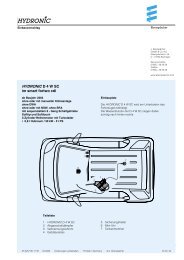
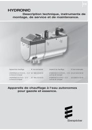
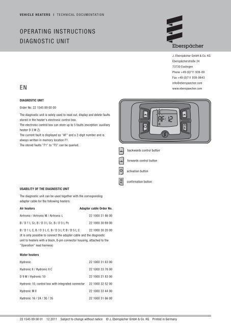
<strong>Diag</strong>nostic <strong>unit</strong><br />
order no. 22 1545 89 00 00<br />
The diagnostic <strong>unit</strong> is solely used to read out, display and delete faults<br />
stored in the heater's electronic control box.<br />
The electronic control box can store up to 5 faults (exception: auxiliary<br />
heater D 3 W Z).<br />
The current fault is displayed as "aF" and a 2-digit number and is<br />
always written in memory location F1.<br />
The stored faults "F1" to "F5" can be queried.<br />
usability of the <strong>Diag</strong>nostic <strong>unit</strong><br />
The diagnostic <strong>unit</strong> can be used together with the corresponding<br />
adapter cable for the following heaters:<br />
air heaters adapter cable order no.<br />
airtronic / airtronic m / airtronic l 22 1000 31 86 00<br />
B / D 1 l Cc, B / D 3 l Cc, B / D 3 l Pc 22 1000 30 69 00<br />
B / D 1 l C, B / D 3 l C, B / D 3 l P, B / D 5 l C 22 1000 30 <strong>20</strong> 00<br />
(it is only possible to connect the adapter cable and the diagnostic<br />
<strong>unit</strong> to heaters with a black, 8-pin connector housing, attached to the<br />
"operation" lead harness)<br />
Water heaters<br />
Hydronic 22 1000 31 63 00<br />
Hydronic ii / Hydronic ii C 22 1000 33 78 00<br />
D 9 W / Hydronic 10 22 1000 31 83 00<br />
Hydronic 10, control box with integrated connector 22 1000 32 52 00<br />
Hydronic m ii 22 1000 33 44 00<br />
Hydronic 16 / 24 / 30 / 35 22 1000 31 66 00<br />
backwards control button<br />
forwards control button<br />
activation button<br />
confirmation button<br />
22 1545 89 00 01 12.<strong>20</strong>11 Subject to change without notice © J. Eberspächer GmbH & Co. KG Printed in Germany<br />
J. Eberspächer GmbH & Co. KG<br />
Eberspächerstraße 24<br />
73730 Esslingen<br />
Phone +49 (0)711 939-00<br />
Fax +49 (0)711 939-0643<br />
info@eberspaecher.com<br />
www.eberspaecher.com
2 | Vehicle Heaters – Technical Documentation<br />
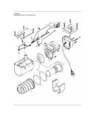
connect <strong>Diag</strong>nostic <strong>unit</strong><br />
air heaters<br />
Disconnect the plug-in connection in the "Heater / Cable harness"<br />
cable loom.<br />
Connect the adapter cable to the "Heater" cable loom and to the<br />
cable harness.<br />
Connect the 6-pin push-on sleeve housing of the adapter cable with<br />
the 6-pin tab connector housing of the diagnostic <strong>unit</strong>.<br />
Please note!<br />
Before starting the diagnosis, the controller of all air heaters operated<br />
with a control <strong>unit</strong> or a mini-controller must be set to max. heat<br />
output.<br />
Water heaters<br />
hydronic<br />
Disconnect the plug-in connection in the "Heater / Cable harness"<br />
cable loom.<br />
Connect the adapter cable to the "Heater" cable loom and to the<br />
cable harness.<br />
Select heater type "Parking heater" or "auxiliary heater" at the<br />
changeover switch.<br />
Connect the 6-pin push-on sleeve housing of the adapter cable with<br />
the 6-pin tab connector housing of the diagnostic <strong>unit</strong>. Start the vehicle<br />
engine also if an auxiliary heater is installed.<br />
hyDronic ii / hyDronic ii c<br />
Disconnect the "<strong>Diag</strong>nosis" plug-in connection in the "Heater" cable<br />
loom.<br />
Connect the 3-pin connector housing of the adapter cable to the<br />
"<strong>Diag</strong>nosis" plug-in connection.<br />
Connect the 6-pin push-on sleeve housing of the adapter cable with<br />
the 6-pin tab connector housing of the diagnostic <strong>unit</strong>.<br />
D 9 W / hydronic 10<br />
Disconnect the plug-in connection in the "operation" cable loom.<br />
Connect the adapter cable to the "operation" cable loom.<br />
Connect the 6-pin push-on sleeve housing of the adapter cable with<br />
the 6-pin tab connector housing of the diagnostic <strong>unit</strong>.<br />
hydronic M / hydronic M ii<br />
remove the "Heater" cable loom from the heater (control box).<br />
Connect the adapter cable to the heater and the cable loom.<br />
Connect the 6-pin push-on sleeve housing of the adapter cable with<br />
the 6-pin tab connector housing of the diagnostic <strong>unit</strong>.<br />
Water heaters<br />
hydronic l / hydronic l ii<br />
Disconnect both plug-in connections in the "Heater / Cable harness"<br />
cable loom.<br />
Connect both plug-in connections to the adapter cable and the cable<br />
loom.<br />
Connect the 6-pin push-on sleeve housing of the adapter cable with<br />
the 6-pin tab connector housing of the diagnostic <strong>unit</strong>.<br />
Please note!<br />
always follow the given order of steps.<br />
The test duration is limited to max. 1<strong>20</strong> minutes.<br />
The bl/ws diagnostic cable must be connected in order to perform<br />
the diagnosis. To this end, note and follow the circuit diagram in the<br />
technical description of the heater.<br />
Ensure adequate battery voltage (min. 10.5 V / min. 21 V).<br />
not only the defective component, but also a defective current path<br />
results in a fault being displayed.<br />
The fault code, fault description, cause / remedial action are<br />
described in the heater's troubleshooting.
PerforM the <strong>Diag</strong>nosis<br />
automatic detection<br />
Five seconds after the diagnostic <strong>unit</strong> has been connected to the heater<br />
using the adapter cable, the automatic detection starts to determine the<br />
type of heater to which the diagnostic <strong>unit</strong> is connected.<br />
Please note!<br />
if the automatic detection was successful, if necessary, the heater is<br />
briefly started and then switches off again.<br />
Display until the automatic detection is completed.<br />
Display<br />
if a water heater has been detected<br />
if air heaters 1l, 3l, 5l or airtronic, airtronic<br />
m, airtronic l air heaters (control box<br />
cable loom fixed, moulded) were detected.<br />
Display,<br />
if the airtronic, airtronic m, airtronic l air<br />
heaters (control box cable loom wound with<br />
cable tape) were detected.<br />
Confirm flashing symbol with<br />
possible displays:<br />
if no errors/faults exist<br />
further action –> display fault memory,<br />
delete fault memory.<br />
if errors/faults exist<br />
further actions –> display current fault and<br />
fault memory, delete fault memory.<br />
Display current fault in fault memory<br />
Simultaneously press and<br />
Display: e.g. aF : 12<br />
Display fault memory f1 – f5<br />
press or<br />
Display: e.g. F1 : <strong>20</strong><br />
Display current fault in the fault memory again<br />
Simultaneously press and<br />
Display: e.g. aF : 12<br />
Vehicle Heaters – Technical Documentation | 3<br />
Delete the fault memory and as a result, at the same time cancel<br />
the control box lock<br />
Current fault or fault F1 – F5<br />
confirm with .<br />
Confirm display dEl again with .<br />
The fault memory is deleted and the control<br />
box is unlocked.<br />
Quit <strong>Diag</strong>nosis<br />
switch off heater<br />
Press , the heater is switched off.<br />
PerforM the <strong>Diag</strong>nosis again<br />
Press , the display is activated.<br />
For further procedure, see left-hand column.
4 | Vehicle Heaters – Technical Documentation<br />
unable to PerforM the <strong>Diag</strong>nosis<br />
automatic detection was unsuccessful<br />
Display if the automatic detection was not<br />
successfully completed.<br />
Possible causes:<br />
bl/ws diagnostic cable not connected<br />
bl/ws diagnostic cable is defective<br />
–> check for continuity, short circuit and damage.<br />
Heater was not detected.