61002 Air Show Instructions - Estes Rockets
61002 Air Show Instructions - Estes Rockets
61002 Air Show Instructions - Estes Rockets

You also want an ePaper? Increase the reach of your titles
YUMPU automatically turns print PDFs into web optimized ePapers that Google loves.
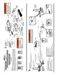
1. ASSEMBLE POWER POD<br />
REAR<br />
1"<br />
(25 mm)<br />
A. Measure and mark engine mount tube at<br />
1” (25 mm), 2-3/8” (6 cm) and 7” (17.8 cm).<br />
D. Use a cotton swab and smear glue 2” (5.1 cm) inside<br />
rear of engine mount tube.<br />
F. Apply glue around tube just ahead of the 1” (25 mm)<br />
mark. Position and insert engine hook into slit as shown.<br />
GREEN<br />
CENTERING RING<br />
2-3/8"<br />
(6 cm)<br />
REAR<br />
7"<br />
(17.8 cm)<br />
7"<br />
(17.8 cm)<br />
H. Apply glue around tube just ahead of 7” (17.8 cm) mark.<br />
Slide second green centering ring onto engine mount tube<br />
up to the 7” (17.8 cm) mark.<br />
BODY TUBE<br />
REAR<br />
J. Smear glue up to 1/2” (13 mm) inside end of body tube.<br />
Insert engine mount sub-assembly into tube until second<br />
green centering ring is flush with end of tube.<br />
2-3/8"<br />
(6 cm)<br />
B. Cut a 1/8” (3 mm) slit at the<br />
2-3/8” (6 cm) mark.<br />
YELLOW<br />
SPACER TOOL<br />
ENGINE<br />
BLOCK<br />
3/8"<br />
(10 mm)<br />
C. Mark yellow spacer tool<br />
3/8” (10 mm) from end.<br />
E. Using yellow spacer tool, push engine block into engine mount tube, up<br />
to mark on tool. Remove yellow spacer tool immediately. Let dry.<br />
GREEN<br />
CENTERING RING<br />
G. Slide one green centering ring (engine hook<br />
retainer) onto engine mount tube and over<br />
engine hook up to the 1” (25 mm) mark.<br />
I. Apply glue around end of tube and slide third<br />
green centering ring onto tube, flush with end.<br />
Let assembly dry.<br />
K. Completed power pod. Let dry.<br />
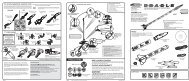
2. INSTALL SHOCK CORD MOUNT<br />
SHOCK CORD<br />
MOUNT<br />
SECTION 3<br />
SECTION 2<br />
SECTION 1<br />
SHOCK CORD<br />
MOUNT<br />
SECTION 3<br />
SECTION 2<br />
SECTION 1<br />
A. Cut out shock cord<br />
mount at left.<br />
3. ATTACH PARACHUTE<br />
A. Form loop in<br />
shroud lines.<br />
SHOCK CORD<br />
D. Apply glue. Fold forward.<br />
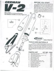
4. ATTACH RUDDER ASSEMBLIES<br />
SIDES<br />
FRONT<br />
A. Smear white glue on bottom, sides and<br />
front of one rudder assembly as shown.<br />
C. Repeat for other<br />
jet. Let dry.<br />
3<br />
B. Fold at<br />
dotted<br />
lines.<br />
3<br />
2<br />
SHOCK<br />
CORD<br />
C. Apply glue.<br />
Fold forward.<br />
E. Squeeze tightly and hold<br />
for one minute.<br />
B. Pass shock cord through loop and tie shock<br />
cord to parachute using a double knot.<br />
B. Attach rudder assembly<br />
to rear of jet. Let dry.<br />
1<br />
F. Glue shock cord<br />
mount 1” (25 mm)<br />
inside front of<br />
power pod. Hold<br />
until glue sets. Let<br />
dry.<br />
1”<br />
(25 mm)<br />
YES<br />
NO<br />
5. BALANCE JETS FOR FLIGHT<br />
A. Place a jet on your thumb and finger<br />
approximately 5” (12.7 cm) from the rear of the<br />
jet as shown. See if it will balance.<br />
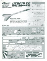
6. GLIDE TEST<br />
B. If jet does not balance, add or remove small<br />
amounts of clay weight to the nose cavity until<br />
the jet is balanced or level while holding it as<br />
shown.<br />
A. Hold jet at eye level, aim at a spot about 50 feet<br />
(15 m) away and toss jet straight out.<br />
B. Observe glide carefully. Make adjustments a little<br />
at a time until you are satisfied with the glide.<br />
C. Once satisfied with glide, press clay firmly into<br />
nose cavity.<br />
GLIDER ADJUSTMENTS:<br />
If jet DIVES: Remove weight, a little at a time, from<br />
nose cavity.<br />
If jet STALLS: Add clay weight, a little at a time, to<br />
nose cavity.<br />
If jet TURNS TOO SHARPLY: Gently bend elevator<br />
section of the down wing up.<br />
The jet should perform a large, gliding circle during<br />
descent.<br />
page 2 page 3 page 4<br />
DOUBLE<br />
KNOT<br />
5"<br />
(12.7 cm)<br />
REPAIRING THE JETS<br />
Use white glue to repair any breaks<br />
in the foam on the jets. Make sure to<br />
let the glue dry completely before<br />
attempting to launch. After the repair,<br />
you should check the balance of the<br />
jet and perform a glide test before<br />
launching. See Step 5 for balancing<br />
and Step 6 for the glide test.<br />
C. Repeat for other jet.<br />
5"<br />
(12.7 cm)<br />
CLAY<br />
CORRECT FLIGHT - SLOW<br />
LOSS OF ALTITUDE<br />
LIGHT STALL - OK<br />
HEAVY STALL - NO GOOD<br />
STEEP DIVE - NO GOOD