61002 Air Show Instructions - Estes Rockets
61002 Air Show Instructions - Estes Rockets
61002 Air Show Instructions - Estes Rockets

Create successful ePaper yourself
Turn your PDF publications into a flip-book with our unique Google optimized e-Paper software.
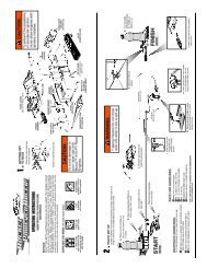
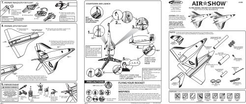
7. PREPARE PARACHUTE FOR FLIGHT<br />
IMPORTANT:<br />
Wadding must be in place<br />
and slide freely for rocket<br />
to work properly.<br />
A. Insert 3-4 squares<br />
of loosely<br />
crumpled recovery<br />
wadding into front<br />
of power pod.<br />
WARNING: FLAMMABLE<br />
To avoid serious injury, read<br />
instructions & NAR Safety Code<br />
included with engines.<br />
PREPARE YOUR ENGINE<br />
ONLY WHEN YOU ARE<br />
OUTSIDE AT THE LAUNCH<br />
SITE PREPARING TO<br />
LAUNCH!<br />
If you do not use your prepared<br />
engine, remove the igniter before<br />
storing your engine.<br />
NOTE: Only <strong>Estes</strong><br />
Wadding (302274)<br />
Recommended.<br />
8. PREPARE JETS FOR FLIGHT<br />
9. PREPARE ENGINE<br />
page 5<br />
B. Spike parachute.<br />
A. Prepare parachute<br />
as instructed.<br />
C. Fold.<br />
SLIDE POWER POD ALL<br />
THE WAY FORWARD.<br />
MASKING<br />
TAPE<br />
D. Hold gliders vertically. Power pod should remain in<br />
place. If power pod does not stay in place, apply a strip<br />
of masking tape on inside of tube and recheck fit. It<br />
must be snug but not too tight, or jets will not separate.<br />
A. Separate<br />
igniter and<br />
plug.<br />
IGNITER MUST<br />
TOUCH<br />
PROPELLANT!<br />
B. Insert<br />
igniter.<br />
C. Insert<br />
plug. D. Push<br />
D. Roll.<br />
E. Wrap lines loosely. Insert<br />
‘chute, and shock cord into<br />
power pod.<br />
IMPORTANT:<br />
Parachute should slide easily<br />
into body. If fit is too tight, unfold<br />
and repack again.<br />
B. Slide power pod onto plastic coupler of one<br />
jet, with engine hook in the center.<br />
C. Holding the jet with the power pod firmly in<br />
one hand, slide the second jet onto the front<br />
of the power pod. Make sure both jets are<br />
secured to the power pod.<br />
down. E. Gently bend<br />
igniter wires<br />
to form leads<br />
as shown.<br />
F. Insert engine<br />
into rocket.<br />
page 6<br />
COUNTDOWN AND LAUNCH<br />
KEY<br />
ALWAYS<br />
OUT UNTIL FINAL<br />
COUNTDOWN! 2...<br />
1...<br />
MASKING<br />
TAPE<br />
8" (20.3 cm)<br />
NOTE:<br />
So that you don’t loose sight<br />
of your jets or power pod,<br />
it’s a good idea to have<br />
another person observe the<br />
launch and recovery, as the<br />
jets and power pod<br />
descend separately.<br />
PRECAUTIONS<br />
NAR Safety Code<br />
NO DRY GRASS<br />
OR WEEDS<br />
2...<br />
5...<br />
3...<br />
4...<br />
4... 3... 2... 1...<br />
15 FT. (5 M)<br />
HOLD KEY DOWN AND<br />
PRESS LAUNCH BUTTON<br />
UNTIL LIFT-OFF!<br />
FLYING YOUR ROCKET<br />
Choose a large field (1000 ft. [305 m] square) free of dry weeds and brown grass.<br />
The larger the launch area, the better your chance of recovering your jets. Football<br />
fields and playgrounds are great. Launch only with little or no wind and good visibility.<br />
Always follow the National Association of Rocketry (NAR) SAFETY CODE.<br />
MISFIRES<br />
TAKE THE KEY OUT OF THE CONTROLLER. WAIT ONE MINUTE BEFORE<br />
GOING NEAR THE ROCKET! Disconnect the igniter clips and remove engine. Take<br />
the plug and igniter out of the engine. If the igniter has burned, it worked but did<br />
not ignite the engine because it was not touching the propellant inside the engine.<br />
Put a new igniter all the way inside the engine without bending it. Push the plug in<br />
place. Repeat the steps under Countdown and Launch.<br />
© 2005 <strong>Estes</strong>-Cox Corp. All rights reserved.<br />
INSERT KEY.<br />
PUSH DOWN<br />
FIRMLY AND<br />
HOLD.<br />
KEY<br />
ESTES LAUNCH SUPPLIES<br />
(Sold Separately)<br />
• Recovery Wadding (included with<br />
some engines)<br />
• Igniters (with Engines)<br />
• Igniter Plugs (with Engines)<br />
• Recommended Engines:<br />
B6-2, C6-3<br />
PN <strong>61002</strong> (02-05)<br />
www.estesrockets.com<br />
ESTES INDUSTRIES<br />
1295 H Street<br />
Penrose, CO 81240<br />
PRINTED IN CHINA<br />
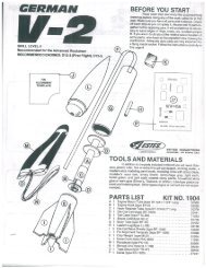
ASSEMBLY TIP: Read all<br />
instructions before beginning<br />
work on your model. Make sure<br />
you have all parts and supplies.<br />
TEST FIT ALL PARTS<br />
TOGETHER BEFORE<br />
APPLYING ANY GLUE!<br />
If any parts don't fit properly,<br />
sand as required for precision<br />
assembly.<br />
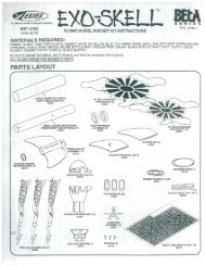
AIR SHOW<br />
FLYING MODEL ROCKET KIT INSTRUCTIONS<br />
KEEP FOR FUTURE REFERENCE<br />
PARTS Locate the parts shown below and lay them out on the table in front<br />
of you. DO NOT USE THIS DRAWING TO ASSEMBLE YOUR ROCKET.<br />
RUDDER<br />
ASSEMBLY (1)<br />
(61011)<br />
RUDDER<br />
ASSEMBLY (1)<br />
(61011)<br />
JET FUSELAGE<br />
W/WING (2)<br />
(61010)<br />
SUPPLIES In addition to the parts included in the kit you will also need:<br />
SCISSORS PENCIL RULER FINE SAND<br />
PAPER<br />
(#400-600 GRIT)<br />
ENGINE MOUNT TUBE<br />
BT-760 7.875” (20 cm) (1)<br />
(31678)<br />
LAUNCH LUG 1/8” X 13”<br />
LL-2 (1)<br />
(38187)<br />
CARPENTER'S<br />
GLUE<br />
BODY TUBE<br />
BT-55 4.25” (10.8 cm) (1)<br />
(31679)<br />
YELLOW SPACER<br />
TOOL ET-2 (1)<br />
(35003)<br />
CLAY WEIGHT (2)<br />
(85705)<br />
WHITE<br />
GLUE<br />
HOBBY<br />
KNIFE<br />
COTTON<br />
SWAB<br />
#1480<br />
GREEN CENTERING<br />
RING RA-76055 (3)<br />
(30133)<br />
GREEN ENGINE<br />
BLOCK AR-520 (1)<br />
(30162-2)<br />
ENGINE HOOK<br />
EH-2 (1)<br />
(35021)<br />
RUBBER SHOCK<br />
CORD 1/8”X18” (1)<br />
(38366)<br />
MASKING<br />
TAPE
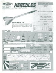
1. ASSEMBLE POWER POD<br />
REAR<br />
1"<br />
(25 mm)<br />
A. Measure and mark engine mount tube at<br />
1” (25 mm), 2-3/8” (6 cm) and 7” (17.8 cm).<br />
D. Use a cotton swab and smear glue 2” (5.1 cm) inside<br />
rear of engine mount tube.<br />
F. Apply glue around tube just ahead of the 1” (25 mm)<br />
mark. Position and insert engine hook into slit as shown.<br />
GREEN<br />
CENTERING RING<br />
2-3/8"<br />
(6 cm)<br />
REAR<br />
7"<br />
(17.8 cm)<br />
7"<br />
(17.8 cm)<br />
H. Apply glue around tube just ahead of 7” (17.8 cm) mark.<br />
Slide second green centering ring onto engine mount tube<br />
up to the 7” (17.8 cm) mark.<br />
BODY TUBE<br />
REAR<br />
J. Smear glue up to 1/2” (13 mm) inside end of body tube.<br />
Insert engine mount sub-assembly into tube until second<br />
green centering ring is flush with end of tube.<br />
2-3/8"<br />
(6 cm)<br />
B. Cut a 1/8” (3 mm) slit at the<br />
2-3/8” (6 cm) mark.<br />
YELLOW<br />
SPACER TOOL<br />
ENGINE<br />
BLOCK<br />
3/8"<br />
(10 mm)<br />
C. Mark yellow spacer tool<br />
3/8” (10 mm) from end.<br />
E. Using yellow spacer tool, push engine block into engine mount tube, up<br />
to mark on tool. Remove yellow spacer tool immediately. Let dry.<br />
GREEN<br />
CENTERING RING<br />
G. Slide one green centering ring (engine hook<br />
retainer) onto engine mount tube and over<br />
engine hook up to the 1” (25 mm) mark.<br />
I. Apply glue around end of tube and slide third<br />
green centering ring onto tube, flush with end.<br />
Let assembly dry.<br />
K. Completed power pod. Let dry.<br />
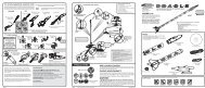
2. INSTALL SHOCK CORD MOUNT<br />
SHOCK CORD<br />
MOUNT<br />
SECTION 3<br />
SECTION 2<br />
SECTION 1<br />
SHOCK CORD<br />
MOUNT<br />
SECTION 3<br />
SECTION 2<br />
SECTION 1<br />
A. Cut out shock cord<br />
mount at left.<br />
3. ATTACH PARACHUTE<br />
A. Form loop in<br />
shroud lines.<br />
SHOCK CORD<br />
D. Apply glue. Fold forward.<br />
4. ATTACH RUDDER ASSEMBLIES<br />
SIDES<br />
FRONT<br />
A. Smear white glue on bottom, sides and<br />
front of one rudder assembly as shown.<br />
C. Repeat for other<br />
jet. Let dry.<br />
3<br />
B. Fold at<br />
dotted<br />
lines.<br />
3<br />
2<br />
SHOCK<br />
CORD<br />
C. Apply glue.<br />
Fold forward.<br />
E. Squeeze tightly and hold<br />
for one minute.<br />
B. Pass shock cord through loop and tie shock<br />
cord to parachute using a double knot.<br />
B. Attach rudder assembly<br />
to rear of jet. Let dry.<br />
1<br />
F. Glue shock cord<br />
mount 1” (25 mm)<br />
inside front of<br />
power pod. Hold<br />
until glue sets. Let<br />
dry.<br />
1”<br />
(25 mm)<br />
YES<br />
NO<br />
5. BALANCE JETS FOR FLIGHT<br />
A. Place a jet on your thumb and finger<br />
approximately 5” (12.7 cm) from the rear of the<br />
jet as shown. See if it will balance.<br />
6. GLIDE TEST<br />
B. If jet does not balance, add or remove small<br />
amounts of clay weight to the nose cavity until<br />
the jet is balanced or level while holding it as<br />
shown.<br />
A. Hold jet at eye level, aim at a spot about 50 feet<br />
(15 m) away and toss jet straight out.<br />
B. Observe glide carefully. Make adjustments a little<br />
at a time until you are satisfied with the glide.<br />
C. Once satisfied with glide, press clay firmly into<br />
nose cavity.<br />
GLIDER ADJUSTMENTS:<br />
If jet DIVES: Remove weight, a little at a time, from<br />
nose cavity.<br />
If jet STALLS: Add clay weight, a little at a time, to<br />
nose cavity.<br />
If jet TURNS TOO SHARPLY: Gently bend elevator<br />
section of the down wing up.<br />
The jet should perform a large, gliding circle during<br />
descent.<br />
page 2 page 3 page 4<br />
DOUBLE<br />
KNOT<br />
5"<br />
(12.7 cm)<br />
REPAIRING THE JETS<br />
Use white glue to repair any breaks<br />
in the foam on the jets. Make sure to<br />
let the glue dry completely before<br />
attempting to launch. After the repair,<br />
you should check the balance of the<br />
jet and perform a glide test before<br />
launching. See Step 5 for balancing<br />
and Step 6 for the glide test.<br />
C. Repeat for other jet.<br />
5"<br />
(12.7 cm)<br />
CLAY<br />
CORRECT FLIGHT - SLOW<br />
LOSS OF ALTITUDE<br />
LIGHT STALL - OK<br />
HEAVY STALL - NO GOOD<br />
STEEP DIVE - NO GOOD