Manual - ETS-Lindgren
Manual - ETS-Lindgren
Manual - ETS-Lindgren

You also want an ePaper? Increase the reach of your titles
YUMPU automatically turns print PDFs into web optimized ePapers that Google loves.
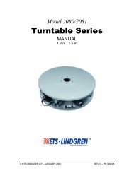
Turntable<br />
Model 2188<br />
1.2m, 1.5m and 2.0m<br />
Users <strong>Manual</strong><br />
©<strong>ETS</strong>-<strong>Lindgren</strong>—January, 2006 Rev. B—Part#399771
Model 2188 Turntable<br />
<strong>ETS</strong>-<strong>Lindgren</strong> reserves the right to make changes to any products herein to improve functioning<br />
or design. Although the information in this document has been carefully reviewed and is believed<br />
to be reliable, <strong>ETS</strong>-<strong>Lindgren</strong> does not assume any liability arising out of the application or use of<br />
any product or circuit described herein; nor does it convey any license under its patent rights nor<br />
the rights of others.<br />
©Copyright 2006 by <strong>ETS</strong>-<strong>Lindgren</strong> L.P. All Rights Reserved. No part of this document may be<br />
copied by any means without written permission from <strong>ETS</strong>-<strong>Lindgren</strong> L.P.<br />
2<br />
Revision Description Date<br />
A Initial Release November, 2005<br />
B Added two meter turntable information, updated<br />
illustrations and drawings<br />
January, 2006<br />
E-Mail & Internet Addresses<br />
support@ets-lindgren.com<br />
http://www.ets-lindgren.com<br />
USA<br />
1301 Arrow Point Drive, Cedar Park, TX 78613 USA<br />
P O Box 80589, Austin, TX 78708-0589 USA<br />
Tel. +512.531.6400<br />
Fax +512.531.6500<br />
Finland<br />
Mekaanikontie 1, 27510, Eura, Finland<br />
Tel. +358.2.838.330<br />
Fax +358.2.865.1233<br />
Japan<br />
4-2-6, Kohinata<br />
Bunkyo-ku, Tokyo 112-0006 Japan<br />
Tel. +81.3.3813.7100<br />
Fax +81.3.3813.8068<br />
China<br />
1917-1918 Xue Zhixuan Building<br />
No. 16 Xue Qing Road<br />
Haidian District<br />
Beijing Postcode: 100083 China<br />
Tel. +86.010.827.55304<br />
Fax +86.010.827.55307<br />
©<strong>ETS</strong>-<strong>Lindgren</strong>—January, 2006<br />
Rev. B—P#399771
©<strong>ETS</strong>-<strong>Lindgren</strong>—January, 2006<br />
Rev. B—P#399771<br />
Table of Contents<br />
Model 2188 Turntable<br />
1. Introduction.................................................................................................................................. 7<br />
1.1. Standard Configuration......................................................................................................... 7<br />
1.2. Model 2188 Options.............................................................................................................. 8<br />
1.2.1. Model 2090 Series Positioning Controller...................................................................... 8<br />
1.2.2. Additional Fiber Optic Cable .......................................................................................... 9<br />
2. Getting Started........................................................................................................................... 11<br />
2.1. Unpacking and Acceptance ................................................................................................ 11<br />
2.2. Electrical Specifications ...................................................................................................... 11<br />
2.2.1........................................................................................................................................ 11<br />
2.2.2. Mechanical ................................................................................................................... 12<br />
2.3. Turntable Installation Considerations ................................................................................. 12<br />
2.3.1. Conduit ......................................................................................................................... 12<br />
2.3.2. Electrical Considerations.............................................................................................. 12<br />
2.3.3. Access.......................................................................................................................... 12<br />
3. Installation.................................................................................................................................. 13<br />
3.1. Tools Required.................................................................................................................... 13<br />
3.2. Unpacking ........................................................................................................................... 14<br />
3.3. Positioning the Turntable .................................................................................................... 14<br />
3.4. Installing Anchor Plates ...................................................................................................... 16<br />
3.5. Raised Panel Floor Flange Installation ............................................................................... 17<br />
3.6. Floor Flange Mounting in a Concrete Pit ............................................................................ 18<br />
3.7. Motorbase Attachment........................................................................................................ 19<br />
3.8. Final Leveling of the Table.................................................................................................. 20<br />
3.9. Application of Conductive Grease ...................................................................................... 20<br />
4. Electrical Installation.................................................................................................................. 21<br />
5. Operation................................................................................................................................... 23<br />
5.1. Editing Positioning Controller Configuration Parameters ................................................... 23<br />
5.2. Setting Travel Limits ........................................................................................................... 24<br />
5.3. Turntable Encoder Calibration ............................................................................................ 25<br />
5.3.2. Turntable Calibration Example..................................................................................... 26<br />
5.4. Changing Rotation Speed................................................................................................... 27<br />
5.5. Variable Speed Settings ..................................................................................................... 27<br />
5.6. Speed Selection.................................................................................................................. 28<br />
5.7. GPIB Commands ................................................................................................................ 29<br />
6. Infrared Controller...................................................................................................................... 31<br />
7. Recommended Maintenance..................................................................................................... 33<br />
7.1. Routine Maintenance .......................................................................................................... 33<br />
7.2. Bi-Annual Maintenance....................................................................................................... 33<br />
7.3. Annual Maintenance ........................................................................................................... 34<br />
8. Warranty .................................................................................................................................... 37<br />
9. Addendum A: Drawings............................................................................................................ 39<br />
3
Model 2188 Turntable<br />
4<br />
SAFETY SYMBOL DEFINITIONS<br />
NOTICE: This product and related documentation must be reviewed for familiarization<br />
with safety markings and instructions prior to operation of the product.<br />
REFER TO MANUAL—When the product is marked with<br />
this symbol refer to the instruction manual for additional<br />
information. If the instruction manual has been misplaced,<br />
! OR<br />
go to www.ets-lindgren.com for downloadable files or<br />
contact <strong>ETS</strong>-<strong>Lindgren</strong> customer service.<br />
HIGH VOLTAGE—Indicates the presence of hazardous<br />
voltage. Unsafe practice could result in several personal<br />
injury or death.<br />
OR<br />
PROTECTIVE EARTH GROUND (SAFETY GROUND)—<br />
Indicates protective earth terminal. Uninterruptible safety<br />
earth ground from the main power source to the product<br />
input wiring terminals, power cord or supplied power cord<br />
set shall be provided.<br />
CAUTION—Denotes a hazard. Failure to follow<br />
instructions could result in minor personal injury and/or<br />
CAUTION<br />
property damage. Text that follows the symbol will provide<br />
proper procedures.<br />
WARNING—Denotes a hazard. Failure to follow instruction<br />
could result in SEVERE personal injury and/or property<br />
WARNING<br />
damage. Text that follows the symbol will provide proper<br />
procedures.<br />
GENERAL SAFETY CONSIDERATIONS/PRECAUTIONS<br />
Read this manual completely before beginning the<br />
installation of the turntable. Refer to drawings at the rear of<br />
the manual and the “Tools Required” list included prior to<br />
beginning installation. This equipment should be installed<br />
and operated only by qualified personnel.<br />
The electrical installation of this product should be<br />
accomplished by an individual who is authorized to so do by<br />
the appropriate local authority. The installation should be in<br />
compliance with local electrical safety codes.<br />
BEFORE POWER IS APPLIED TO THIS INSTRUMENT,<br />
GROUND IT PROPERLY through the protective conductor<br />
of the AC power cable to a power source provided with<br />
protective earth contact. Any interruption of the protective<br />
(grounding) conductor, inside or outside of the instrument,<br />
or disconnection of the protective earth terminal could result<br />
in personal injury.<br />
©<strong>ETS</strong>-<strong>Lindgren</strong>—January, 2006<br />
Rev. B—P#399771
©<strong>ETS</strong>-<strong>Lindgren</strong>—January, 2006<br />
Rev. B—P#399771<br />
Model 2188 Turntable<br />
GENERAL SAFETY CONSIDERATIONS/PRECAUTIONS (continued)<br />
WARRANTY<br />
WARRANTY<br />
WARRANTY<br />
BEFORE SERVICING: CONTACT <strong>ETS</strong>-LINDGREN<br />
(+1.512.531.6400)—servicing or modifying the unit without<br />
<strong>ETS</strong>-<strong>Lindgren</strong> authorization may void your warranty. If an<br />
attempt to service the unit must be made, disconnect all<br />
electrical power prior to beginning. Voltages exist at many<br />
points within the instrument that could, if contacted, cause<br />
personal injury. Only trained service personnel should<br />
perform adjustments and/or service procedures upon this<br />
instrument. Capacitors inside this instrument may still be<br />
CHARGED even when the instrument is disconnected from<br />
the power source.<br />
Do not make any modifications to this unit without<br />
consulting the factory directly.<br />
ONLY QUALIFIED PERSONNEL should operate or service<br />
this equipment.<br />
STAY CLEAR of moving components during operation of<br />
equipment. Do not operate the turntable while someone is<br />
physically on the turntable top.<br />
Do not, at any time, place hands or feet in the vicinity of the<br />
drive pinion on the turntable.<br />
Regularly inspect all equipment and conduct scheduled<br />
maintenance in accordance with the factory<br />
recommendations provided.<br />
Only use replacement parts and fasteners ordered directly<br />
from the factory.<br />
5
Model 2188 Turntable<br />
This page intentionally left blank.<br />
6<br />
©<strong>ETS</strong>-<strong>Lindgren</strong>—January, 2006<br />
Rev. B—P#399771
1. Introduction<br />
©<strong>ETS</strong>-<strong>Lindgren</strong>—January, 2006<br />
Rev. B—P#399771<br />
Model 2188 Turntable<br />
The <strong>ETS</strong>-<strong>Lindgren</strong> Model 2188 is an electric-powered, variable-speed<br />
turntable platform system designed for use with an EMCO Model 2090<br />
series positioning controller to perform EMI compliance testing. The Model<br />
2188 is available in 1.2-meter, 1.5-meter and 2.0-meter diameters. The<br />
turntable is ideal for installations in new or existing test locations where pit<br />
excavation is not an option or must be shallow.<br />
The top of the turntable is conductive with a continuous ground brush to<br />
electrically couple it to the ground plane. The ground brushes are attached<br />
directly to the chamber floor via the floor flange and are in continuous<br />
contact with the turntable top. The brushes point downward from the floor<br />
flange. .<br />
The drive motor and gearing are located beneath the platform. The Model<br />
2188 turntable is powered by an electric motor through a worm gear box<br />
with a chain and sprocket final drive. The top of the turntable is removable<br />
to provide easy access in the event that service is required. The<br />
electronics are located in a shielded enclosure. Signal I/O is via fiber-optic<br />
cable.<br />
To prevent over-travel of the turntable in either direction of movement,<br />
“hard” limits are provided in the form of pins that actuate switches located<br />
below the tabletop. These pins allow limits to be set and allow as much as<br />
two full rotations. Rotation speed can be varied from the front panel of the<br />
controller or through the IEEE-488 interface bus.<br />
1.1. Standard Configuration<br />
• Turntable Assembly<br />
• Single-phase electric drive (208-230 VAC 50/60 Hz)<br />
• Variable speed drive<br />
• Conductive top<br />
• Continuous rotation<br />
• One (1) ten meter fiber-optic control cable<br />
• Fiber optic shield penetration kit<br />
• Two (2) fiber optic feed-thrus<br />
• One (1) three meter fiber optic control cable<br />
7
Model 2188 Turntable<br />
8<br />
1.2. Model 2188 Options<br />
1.2.1. Model 2090 Series Positioning Controller<br />
The Model 2090 Series Multi-Device Positioning Controller is<br />
designed for use with <strong>ETS</strong>-<strong>Lindgren</strong> positioning devices<br />
such as antenna towers, turntables, reverberation paddles,<br />
multi-axis positioners, etc. to accomplish a variety of tests for<br />
EMC compliance, antenna pattern measurements, and<br />
more.<br />
The Controller allows the user to synchronize the<br />
simultaneous, yet independent movement of two primary<br />
devices such as towers or turntables in either manual or<br />
remote GPIB modes while controlling the on/off operation of<br />
up to four auxiliary devices. The unit includes a GPIB bus<br />
and is compatible with most popular software. Firmware<br />
revision 3.11 or higher required.<br />
Each primary device is interfaced to the controller through a<br />
bi-directional fiber optic interface using a proprietary<br />
command protocol. Auxiliary devices use a single fiber optic<br />
signal to control simple on/off operation. The fiber optic<br />
control lines that attach devices to the unit eliminate<br />
extraneous RF interference signals that can normally be<br />
conducted through wire signal cables.<br />
The front panel of the Model 2090 provides the interface for<br />
two separate and complete device controllers, each with<br />
identical displays and function keys. The function keys let<br />
the user configure device specific parameters, adjust limit<br />
and position settings and control device motion. Numeric<br />
displays and status indicators are provided for each device<br />
interface to show positioning and operational information as<br />
well as device parameter settings. In addition to the two<br />
primary device interfaces, an auxiliary control interface for<br />
four auxiliary devices is present. This interface provides<br />
keys and indicators to allow the user to manually toggle the<br />
auxiliary devices on or off.<br />
©<strong>ETS</strong>-<strong>Lindgren</strong>—January, 2006<br />
Rev. B—P#399771
©<strong>ETS</strong>-<strong>Lindgren</strong>—January, 2006<br />
Rev. B—P#399771<br />
Model 2188 Turntable<br />
Control of all devices may be accomplished either in the<br />
manual or remote modes through the use of the GPIB (IEEE<br />
488 standard interface bus) port located on the rear panel.<br />
Each primary device is identified by a unique GPIB address<br />
that the controller recognizes, allowing each positioning<br />
device to function as a separate device on the GPIB bus.<br />
1.2.2. Additional Fiber Optic Cable<br />
Various lengths of fiber optic cable may be ordered. Specify<br />
additional cable lengths at the time of order placement.<br />
Cables are terminated with type ST connectors.<br />
9
Model 2188 Turntable<br />
This page intentionally left blank.<br />
10<br />
©<strong>ETS</strong>-<strong>Lindgren</strong>—January, 2006<br />
Rev. B—P#399771
2. Getting Started<br />
2.1. Unpacking and Acceptance<br />
©<strong>ETS</strong>-<strong>Lindgren</strong>—January, 2006<br />
Rev. B—P#399771<br />
Model 2188 Turntable<br />
Step 1. Upon delivery of your order, inspect the shipping<br />
container(s) for evidence of damage. Record any damage on the<br />
delivery receipt before signing. In case of concealed damage or<br />
loss, retain the packing materials for inspection by the carrier.<br />
Step 2. Once all of the materials are removed from the container<br />
by a qualified installer, check all materials against the packing list to<br />
verify that the equipment received matches what was ordered. If<br />
you find any discrepancies, note them and call <strong>ETS</strong>-<strong>Lindgren</strong><br />
Customer Service (+1.512.531.6400) for further instructions.<br />
Ensure that you are satisfied with the contents of your order and<br />
the condition of your equipment prior to installation.<br />
Pre-planning is essential for a successful installation. Be sure to<br />
discuss your requirements with your sales representative and<br />
request dimensional drawings prior to construction of your site.<br />
2.2. Electrical Specifications<br />
Nominal AC Voltage 230 VAC<br />
Input Frequency 50/60 Hz<br />
Phase Single Phase<br />
AMP 2.0<br />
RPM 0.5/2.0 variable<br />
Table 1: Electrical Specifications<br />
11
Model 2188 Turntable<br />
12<br />
2.2.1. Mechanical<br />
Diameter 1.2 meter 1.5 meter 2.0 meter<br />
Height 16.51 cm 16.51 cm 16.51 cm<br />
(Minimum) (6.12 in.) (6.12 in.) (6.12 in.)<br />
Distributed 500 kg 1,000 kg 1,000 kg<br />
Load<br />
Rating*<br />
(1,100 lb) (2,200 lb) (2,200 lb)<br />
*Distributed Load Rating is based on an evenly distributed<br />
load to each section. Point loads under 0.37 sq. m<br />
(4 sq. ft) should not exceed 500 kg (1,100 lb.). Nothing over<br />
400 kg (882 lb.) may be applied to a 45-degree segment<br />
outboard of the casters.<br />
Table 2: Mechanical Parameters<br />
2.3. Turntable Installation Considerations<br />
2.3.1. Conduit<br />
Power and signal line paths must be planned in advance.<br />
Power and signal lines must never run through the same<br />
conduit. Conduit must be in place before pouring concrete<br />
or installing the ground plane. Consider the size of the cable<br />
bundle when selecting conduit diameter.<br />
2.3.2. Electrical Considerations<br />
A qualified and licensed electrical contractor must be used to<br />
install power lines, and the installation should comply with all<br />
applicable regulatory agencies. A dedicated circuit is<br />
required with the shortest distance possible between the<br />
power source and the turntable.<br />
2.3.3. Access<br />
An access area underneath the turntable is advisable for<br />
large diameter installations. A service switch is necessary to<br />
deactivate the turntable during service.<br />
©<strong>ETS</strong>-<strong>Lindgren</strong>—January, 2006<br />
Rev. B—P#399771
3. Installation<br />
©<strong>ETS</strong>-<strong>Lindgren</strong>—January, 2006<br />
Rev. B—P#399771<br />
Model 2188 Turntable<br />
The turntable installation will vary based on the host location. Several<br />
installation options may be presented in the steps that follow. Please<br />
select the option that applies to your location.<br />
The installation of turntables must be performed by a factory installation<br />
specialist or by individuals who have been authorized by <strong>ETS</strong>-<strong>Lindgren</strong> to<br />
do such work. Proper installation of the turntable directly affects<br />
performance. The following installation information is provided to<br />
familiarize the user of the turntable with the installation process.<br />
CAUTION: Ensure power is off and secured before proceeding further.<br />
3.1. Tools Required<br />
• 3/16” Allen wrench<br />
• ¼” Allen wrench<br />
• 3/8” Allen wrenches, qty 3<br />
• 6 mm Allen wrench<br />
• 3/8” ratchet wrench<br />
• 12” crescent wrench<br />
• 15 mm, 12 point socket for<br />
½” square head screws<br />
• 7/16” open/box end wrench<br />
• ½” open/box end wrench<br />
• ¾” open/box end wrench<br />
• 0.120 drill bit for 6-32 self<br />
tapping screws<br />
• #7 Drill bit for ¼-20 tap<br />
• 3/8” hand drill<br />
• 9/32 drill bit<br />
• #2 Phillips screw bit<br />
• #3 Phillips screw bit<br />
• Measuring tape<br />
• Pry bar<br />
• Level<br />
• Square<br />
• Hacksaw<br />
• Black marker<br />
• File<br />
• WD 40<br />
• ¾” pipe clamp ends<br />
• ¾” pipe (length depends on table<br />
size 6 ft. will cover most tables)<br />
• 1 – ½” C-clamps, qty 8<br />
• Cutting Oil<br />
• Syringe for applying conductive<br />
grease<br />
• Grease Gun<br />
• Vacuum<br />
• ½” Hammer Drill<br />
CAUTION: Only qualified personnel must perform lifting of the<br />
turntable assembly using a forklift or other lifting machinery.<br />
Damage to the turntable or serious injury to the personnel may<br />
occur.<br />
13
Model 2188 Turntable<br />
14<br />
3.2. Unpacking<br />
A qualified installer will perform the following steps in preparation for<br />
installation of the turntable. Please pull the drawings from the back pocket<br />
of this manual to assist in the installation directions that follow.<br />
1. Uncrate all parts. Check all parts for any shipping damage. Ensure<br />
a clear area is available to assemble the turntable unit safely.<br />
NOTE: Do not discard any packing material or parts until the<br />
turntable is fully assembled.<br />
2. Verify that that fiber optic cable is long enough to reach from the<br />
turntable to the control room. When working around the table,<br />
avoid stepping on the fiber optic connectors located on the motor<br />
base.<br />
3. If the turntable is to be installed in a pit, check pit depth and inside<br />
diameter and compare measurements with the drawings for your<br />
turntable size at the back of this manual. The inner diameter of the<br />
receptacle pit should be as follows:<br />
• 1.2 meter turntable = 49.00” (+/-0.25”)<br />
• 1.5 meter turntable = 60.00” (+/-0.25”)<br />
• 2.0 meter turntable = 79.75” (+/-0.25”)<br />
4. Remove the bolts that attach the top onto the turntable drive<br />
assembly. These are the six flathead bolts closest to center of the<br />
tabletop. Remove top and place in position as not to damage any<br />
components on the top. Refer to the assembly drawing 2188-1.2,<br />
2188-1.5 or 2188-2.0 included at the rear of this manual for more<br />
details.<br />
3.3. Positioning the Turntable<br />
5. Using a forklift or other appropriate lifting device, place the turntable<br />
bottom into position. The motorbase with the fiber optic connectors<br />
should point in the direction that the fiber optic cable will be<br />
installed. This position will reduce the chance of the cable being<br />
kinked or twisted.<br />
©<strong>ETS</strong>-<strong>Lindgren</strong>—January, 2006<br />
Rev. B—P#399771
©<strong>ETS</strong>-<strong>Lindgren</strong>—January, 2006<br />
Rev. B—P#399771<br />
Figure 1: Turntable Interior Design<br />
Figure 2: Turntable Pit Locator Detail<br />
Model 2188 Turntable<br />
15
Model 2188 Turntable<br />
16<br />
6. Position the table as close as possible to the center. Attach the<br />
measuring bar provided to the brass spacers mounted onto the<br />
bearing. Note the appropriate hole-mount locations in reference to<br />
the size of the turntable to be installed. Rotate the bearing and<br />
ensure approximately 7/8” to 1” spacing exists between the edge of<br />
the outer measuring bar and the diameter of hole cut into the pit.<br />
Adjust if necessary.<br />
7. Once the center is located, using a marker, mark around the<br />
perimeter of the table base or outer floor plates. These marks may<br />
be used for reference if the assembly moves during placement of<br />
the floor shims or anchor plates.<br />
NOTE: When installing the turntable on modular shielding, attempt<br />
to make as many anchor holes miss the floor joint strips as possible<br />
when positioning the table. Use the shim plates provided for this<br />
application.<br />
8. The Model 2188 turntable includes curved floor anchor plates that<br />
are under the base unit. The 1.5m and 2.0m model includes an<br />
outer ring of floor plates to support additional casters. Place<br />
between the base unit and outer plates, the four connector strips<br />
included to ensure proper spacing. Please refer to drawing number<br />
2188-1.2, 2188-1.5 or 2188-2.0 included at the back of this manual<br />
and figure two for the placement and securing of floor plates. If the<br />
turntable is to be installed in a welded chamber with a steel pit and<br />
steel raised floor, please refer to step 12.<br />
3.4. Installing Anchor Plates<br />
9. The anchor plates are held in place by ¼-20 screws and set collars.<br />
Screw the anchor plates to the floor using #14x1” #3 square socket<br />
flat head screws. Drill 1/8” pilot holes for these screws and vacuum<br />
up shavings so that you have good contact with the floor. Continue<br />
mounting the rest of the plates.<br />
10. Once all anchor plates are securely mounted, remove the ¼ -20<br />
screws that hold the anchor plates to the base and discard.<br />
11. Proceed to level the table to the raised floor.<br />
©<strong>ETS</strong>-<strong>Lindgren</strong>—January, 2006<br />
Rev. B—P#399771
©<strong>ETS</strong>-<strong>Lindgren</strong>—January, 2006<br />
Rev. B—P#399771<br />
Model 2188 Turntable<br />
12. When mounting to a steel pit and steel raised floor, a #7 drill bit for<br />
tapping or a 9/32 drill bit to create “through holes” is required when<br />
mounting anchor plates to the steel raised floor. Locate and mark<br />
holes in each group of anchor plates. Drill and tap or drill through<br />
each hole and then screw in ¼-20 hardware so that the table does<br />
not move as you go around each location. Proceed with leveling<br />
instructions.<br />
CAUTION: Before leveling make sure all ½-13 flange nuts and<br />
clamp collars are backed off all the way to avoid pulling plates off<br />
the floor. Refer to drawings at the back of this manual.<br />
13. Raise the table by turning the ½-13 square head screws clockwise<br />
until the measuring bar top is 3/16” above the raised floor; this is<br />
just a rough finish height. Check height with a leveling instrument<br />
(torpedo laser level or some other device).<br />
Once the table is leveled, tighten flange nuts on the square head<br />
screws and secure set collars on the torque pins down onto the<br />
base top surface and outer plate if applicable. Remove the<br />
measuring bar. Refer to figure three and drawing 2188-1.2 at the<br />
rear of the manual for more details.<br />
3.5. Raised Panel Floor Flange Installation<br />
Figure 3: Turntable Elevation View<br />
The ground ring assembly includes a floor flange with a mounted<br />
brush ring that interfaces with the contact ring mounted underneath<br />
the turntable top. The floor flange provides constant electrical<br />
contact with the ground plane.<br />
17
Model 2188 Turntable<br />
18<br />
Mounting methods vary according to user specifications.<br />
Clearance holes are provided, at evenly spaced intervals, along the<br />
outside perimeter of the ground ring as a means of attaching the<br />
ring to a customer supplied ground plane. These instructions cover<br />
installation for a paneled floor; please see the section on “Floor<br />
Flange Mounting in Concrete Pit” for further instructions regarding<br />
mounting in a concrete pit.<br />
For this step you will need three ¼” spacers i.e. bolts, drill bits, etc.<br />
A hand drill, 5/32” drill bit, #3 Phillips drive bit, a small square, #14 x<br />
1 wood/metal screws are also required at this time.<br />
The turntables described in this manual each have two floor flange<br />
pieces. All of the flanges are pre-cut at the factory for drop in fit.<br />
Lay the floor flange into the opening of the raised floor and push<br />
outward to the diameter of the opening. Attach the turntable top<br />
onto the brass spacers with the hardware provided.<br />
14. Using a pipe clamp and ¼” Allen wrenches or ¼” pin, place a<br />
spacer between the turntable and flange starting in three places in<br />
the center or on the flange. Once tension exists on all three<br />
wrenches, drill a 5/32” hole through the counter-sunk holes in the<br />
floor flange. Drill completely through the panel and place screws<br />
into the holes. Continue working around the flange completing two<br />
or three holes at a time. Refer to the 2188 1.2 drawing included for<br />
details<br />
NOTE: It is very important that a ¼” gap between turntable top and<br />
ground brush flange mounted on floor flange be held as close as<br />
possible so that the grounding brushes seat properly. Also, it is<br />
important to ensure the flange ends are flush with each other.<br />
15. Continue mounting as stated above until all screws have been<br />
installed. Some screws may fall between the floor panel joints. Try<br />
to position the flanges, ensuring as few screws hit these points as<br />
possible, and making certain that the first or last hole in the flange<br />
is not too close to one of these joints. Also, the top floor joint strips<br />
will need to be trimmed to fit up against the flange.<br />
3.6. Floor Flange Mounting in a Concrete Pit<br />
Mounting to concrete is the same with the exception of the<br />
mounting hardware. Instead of the #14 x 1” square socket flat head<br />
screws, you will use ¼ x 1 3/4” Phillips flat head TAPCON screws.<br />
©<strong>ETS</strong>-<strong>Lindgren</strong>—January, 2006<br />
Rev. B—P#399771
©<strong>ETS</strong>-<strong>Lindgren</strong>—January, 2006<br />
Rev. B—P#399771<br />
Figure 4:Turntable Motorbase<br />
Model 2188 Turntable<br />
A ½” hammer drill, 3/16 x 3 ½” min. hammer drill bit, and a vacuum<br />
to clean in holes drilled for maximum thread engagement will be<br />
required for this stage of the installation.<br />
NOTE: When drilling holes, watch out for buried conduit and pit<br />
drainpipes. Drill 3/16” holes 2” min. depth.<br />
3.7. Motorbase Attachment<br />
Locate the box that contains the motorbase. The box also includes<br />
the hardware needed to attach the motorbase to the turntable.<br />
Refer to figure four above to locate the drive chain and bolts to<br />
secure the motorbase. Slide the motorbase between the two rails<br />
provided.<br />
Attach three bolts, flat and lock washers provided on each side of<br />
the motorbase, do not tighten them completely at this time.<br />
Attach the chain around the bearing sprocket and the drive<br />
sprocket. Adjust the mortorbase using the two pusher bolts<br />
provided. Allow only ¼ inch maximum side-to-side motion for<br />
proper chain tension on the motor. Finally, tighten the six securing<br />
bolts.<br />
19
Model 2188 Turntable<br />
20<br />
3.8. Final Leveling of the Table<br />
Once the table is in place with the floor flange and wear strip<br />
mounted, check that the table is level. Ensure that it is level and all<br />
screws, nuts, and collars have been tightened.<br />
3.9. Application of Conductive Grease<br />
Before placing the turntable into operation, apply conductive grease<br />
to the ground brush. Apply the contents of one tube of GC<br />
Electronics conductive grease to the brush. Apply one tube per<br />
meter size of the diameter of the table.<br />
©<strong>ETS</strong>-<strong>Lindgren</strong>—January, 2006<br />
Rev. B—P#399771
4. Electrical Installation<br />
©<strong>ETS</strong>-<strong>Lindgren</strong>—January, 2006<br />
Rev. B—P#399771<br />
Model 2188 Turntable<br />
CAUTION: Electrical connection should only be performed by a qualified<br />
electrician and subject to local electrical codes.<br />
The Model 2188 is designed to operate using 208-230 VAC single-phase<br />
50 or 60Hz power.<br />
The branch circuit supplying power to the motor base should be protected<br />
from excess current according to local electrical codes. <strong>ETS</strong>-<strong>Lindgren</strong> has<br />
provided integral circuit protection in the motor base assembly.<br />
Check that the conductor size is adequate for the motor load and the<br />
distance from the mains source. Improperly sized conductors will lead to<br />
a high voltage drop in the power conductors and cause reduced starting<br />
torque and premature motor failure.<br />
The motor base assembly is provided with an IEC-320 power inlet for<br />
connecting to the mains. Prior to servicing the turntable or the turntable<br />
motor base, remove the power connection for safety.<br />
Connect the fiber-optic control cable and install the power connection per<br />
local electrical code. Please refer to the Model 2090 series positioning<br />
controller manual for instructions on connecting the fiber optic cable. After<br />
the fiber optic cable is installed secure it with a wire tie to one of the<br />
leveling screws.<br />
In order to feed the fiber optic connectors through the waveguide in a<br />
chamber it may be necessary to remove part of the protective sheath.<br />
The removal of a portion of the sheath will allow the connectors to fit<br />
through the hole without bending or kinking the fiber optic cable<br />
excessively. Find the spot in which you will need to remove the sheath<br />
and mark. A very sharp knife is needed to make the splice. Being very<br />
careful, cut around the outside of the sheath at each end of the area<br />
needing to be cut, cut very lightly so as to not cut into the fiber cables.<br />
You should then be able to bend the sheath back and forth until you can<br />
see the fiber cables.<br />
Next, you will need to make a cut down the length of sheath area, being<br />
careful not to cut into fiber cable. You will see two pieces of white string<br />
inside the sheath. Find the string and use it to split the sheath open. Now<br />
insert the cable into the waveguide.<br />
21
Model 2188 Turntable<br />
This page intentionally left blank.<br />
22<br />
©<strong>ETS</strong>-<strong>Lindgren</strong>—January, 2006<br />
Rev. B—P#399771
5. Operation<br />
©<strong>ETS</strong>-<strong>Lindgren</strong>—January, 2006<br />
Rev. B—P#399771<br />
Model 2188 Turntable<br />
Please refer to the Model 2090 series positioning controller manual if you<br />
are unfamiliar with the operation of the unit. A manual is included with<br />
each positioning controller shipment and is also available for download<br />
from our website, www.ets-lindgren.com.<br />
With the assembly of the turntable complete the Model 2090 series<br />
controller must be connected to the unit and power applied to both the<br />
motor base and controller in order to continue. Refer to the electrical<br />
installation section if you have questions about how to connect the fiber<br />
optic cables.<br />
Using the Model 2090 series positioning controller check the CW<br />
(clockwise) and CCW (counter clockwise) rotation in both directions by a<br />
few degrees. The position in degrees increases (+) in the CW direction<br />
and decreases (-) in CCW direction.<br />
The turntable is calibrated in the factory to read out 360 degrees<br />
(+ or - 1 degree) for one complete revolution. If the table is not within this<br />
accuracy, the unit can be re-calibrated per the instructions in the<br />
“Turntable Encoder Calibration” section below.<br />
5.1. Editing Positioning Controller Configuration Parameters<br />
To edit a configuration parameter, press the PARAM key to display<br />
the current parameter. Pressing the PARAM key repeatedly will<br />
scroll down through the parameter list, showing each parameter in<br />
turn. While viewing a parameter, the STEP keys (INC/DEC) may<br />
be used to scroll up or down the parameter list. This reduces the<br />
effort necessary to scan through a long parameter list using the<br />
PARAM key. Pressing any of the LIMIT/POSITION selection keys<br />
will return the display to that selection. Pressing any of the<br />
remaining motion keys will return the display to the current position<br />
and execute that motion. Pressing the PARAM key again will<br />
return to the last displayed parameter in the list, allowing easy<br />
transition between parameter adjustment and device operation.<br />
Once the desired limit, position or parameter is visible in the display<br />
window, pressing INCRM, DECRM, or ENTER will toggle into edit<br />
mode. The lowest adjustable digit will flash on and off. Pressing<br />
the LOCAL key for that device will switch the flashing digit to the<br />
next higher digit. In this way, it is possible to rapidly adjust any digit<br />
of a multi-digit parameter or limit.<br />
23
Model 2188 Turntable<br />
24<br />
5.2. Setting Travel Limits<br />
Figure 5: Turntable Limit Switch<br />
The Model 2188 is fitted with mechanically actuated or “hard” limit<br />
switches. These switches are adjustable to allow for limited travel<br />
beyond zero and 360 degrees. Actuation pins are placed in the<br />
turntable top to engage the limit switch mechanism. The limit<br />
switch mechanism is designed so that the amount of travel is<br />
dictated by the pin position in the turntable top.<br />
The default configuration allows for travel between –45 degrees<br />
and +405 degrees. Remove all pins and the access panel. Move<br />
the turntable so that the access hatch is directly above the limit<br />
switch mechanism (shown in Figure five above). Set the<br />
mechanism to the CCW armed position and insert actuations pins<br />
in the holes on either side of the mechanism 45 degrees away.<br />
Now, set the current position displayed by the controller to 000.0<br />
degrees. Test the lower limit by holding down the DEC key, which<br />
allows the turntable to travel past the soft limit. The turntable<br />
should engage the lower hard limit between -35 and -55 degrees.<br />
You can also test the upper limit by holding down the INC key until<br />
the upper limit is engaged between 395 and 415 degrees.<br />
It is also advised that the user properly set the “soft” limits in the<br />
controller should non-continuous operation be desired.<br />
To set the counterclockwise rotational limit for the turntable, press<br />
the DOWN/CCW key under LIMIT. The indicator above this key will<br />
light. Set the limit by pressing the INCRM and DECRM keys under<br />
LIMIT until the desired limit is shown on the display. Then, press<br />
©<strong>ETS</strong>-<strong>Lindgren</strong>—January, 2006<br />
Rev. B—P#399771
©<strong>ETS</strong>-<strong>Lindgren</strong>—January, 2006<br />
Rev. B—P#399771<br />
Model 2188 Turntable<br />
the ENTER key. To set the clockwise rotational limit for the<br />
turntable, press the UP/CW key under LIMIT. The indicator light<br />
above this key will light. Set the limit by pressing the INCRM and<br />
DECRM keys under LIMIT until the desired limit is shown on the<br />
display. Press the ENTER key.<br />
WARNING: Ensure the current travel limit settings will not cause<br />
damage to existing cables and equipment located underneath the<br />
turntable.<br />
Should continuous operation be desired, the Model 2090 series<br />
controller permits easy configuration to this type of operation from<br />
the front panel or through the IEEE-488 interface bus. Refer to the<br />
positioning controller manual for more information. The limit pins<br />
should also be removed form the turntable top to allow for<br />
continuous operation.<br />
5.3. Turntable Encoder Calibration<br />
Parameter C, which calibrates the encoder counts to the rotation of<br />
the turntable, must be set to the value 3600. Parameter C Refers to<br />
the encoder calibration parameter. This setting is used to convert<br />
the encoder count values returned from a motor base into the<br />
corresponding centimeter or degree position reading. For<br />
turntables, this represents the number of encoder counts per<br />
revolution. The setting for the Model 2188 turntable series is 3600.<br />
If the given value does not appear to work correctly, the encoder<br />
calibration value can be determined using the following procedure:<br />
1. Set the encoder calibration value to 3600.<br />
2. Ensure that the turntable is positioned to allow more than a full<br />
revolution of travel in the clockwise direction and use the STEP<br />
keys to run the turntable clockwise a few degrees to remove any<br />
play in the table.<br />
3. Mark the current location of the turntable against the ground ring<br />
(masking tape works well for marking), and set the current<br />
position reading to 000.0.<br />
4. Using the STEP keys, rotate the turntable clockwise until it is<br />
again aligned with the mark on the ground ring. For best<br />
results, the last motion should always be in the clockwise<br />
direction to ensure that any play in the gearing between the<br />
motor and encoder is accounted for.<br />
25
Model 2188 Turntable<br />
26<br />
5. Record the reading of the display, ignoring the decimal point<br />
(i.e. 360.0 would be 3600). This is the encoder calibration<br />
value.<br />
NOTE: If the value is below 3600, the resolution of the encoder<br />
is low and consequently the controller will not provide 0.1degree<br />
resolution, even though the display shows that digit. If<br />
the value has gone past 9999, the encoder has too many counts<br />
per meter and the controller cannot correct for it. In this case,<br />
contact <strong>ETS</strong>-<strong>Lindgren</strong> for assistance.<br />
6. Enter the encoder calibration value and reset the limits and<br />
position information.<br />
7. Test the turntable by moving it a complete revolution and<br />
comparing the alignment marks. It may be necessary to adjust<br />
the encoder calibration value up or down slightly depending on<br />
the result.<br />
NOTE: When scanning between limits, it is not uncommon to<br />
have a small discrepancy between the absolute position of the<br />
table and the display on the controller. This is because<br />
reversing the direction of rotation reverses any gear play<br />
between the encoder and the table top, allowing that play to be<br />
visible in the positioning accuracy.<br />
5.3.2. Turntable Calibration Example<br />
• The table is set at the “0” degree position. A piece of tape is<br />
placed on the edge of the turntable to line up with the edge<br />
of the gearbox cover. The table is stopped when the tape<br />
travels exactly 360 degrees around. The display on the<br />
controller now reads 356.3 degrees, which is recorded.<br />
• The table is rotated CCW back to zero. The parameter<br />
button is set on the “C” setting. The “C” digits display 3430.<br />
A new “C” setting is now calculated:<br />
• New “C” = (356.3 divided into 360) times 3430 = 3395<br />
(rounded off).<br />
• The decrement the C parameter to 3395 and “ENTER” is<br />
pressed. The “current position” button is pressed to get back<br />
to operation mode.<br />
©<strong>ETS</strong>-<strong>Lindgren</strong>—January, 2006<br />
Rev. B—P#399771
©<strong>ETS</strong>-<strong>Lindgren</strong>—January, 2006<br />
Rev. B—P#399771<br />
Model 2188 Turntable<br />
• The table is rotated from 0 to 360 and the mark is now within<br />
one degree of being one full turntable revolution. Calibration<br />
is complete.<br />
5.4. Changing Rotation Speed<br />
The Model 2188 turntable is equipped with a variable speed drive.<br />
Firmware Revision 3.11 (or higher) must be installed in the Model<br />
2090 series controller for proper operation of the Model 2188. The<br />
revision level is displayed on the front panel LED display during<br />
startup of the Model 2090 series controller. If the controller does<br />
not have this or a later revision installed, consult the factory for an<br />
upgrade.<br />
To select one of the four speeds, use the POLAR/SPEED button to<br />
toggle through the speed options. It is necessary to set the<br />
controller parameters to configure the controller to properly control<br />
the motor base. Refer to the controller manual to the section that<br />
describes setting the parameters.<br />
Specifically, parameter two must be set to the value three, which is<br />
for variable speed control. Parameter C, which calibrates the<br />
encoder counts to the rotation of the turntable, should be set to the<br />
value 5440. This will insure that the position display will properly<br />
report the full 360 degrees of travel.<br />
5.5. Variable Speed Settings<br />
The Model 2090 series controller parameters S1-S4 control the<br />
variable speed settings for the turntable. These parameters are the<br />
continuous variable speed settings for each of the four speed<br />
selections described below. Each of these parameters can be set<br />
to any value from 1 to 255, with the resulting turntable speed being<br />
roughly an S/255 fraction of the maximum speed. Note that it is the<br />
nature of variable speed drives that there is a minimum speed at<br />
which the motor will operate. For the Model 2188 this minimum<br />
speed setting will be somewhere between 30-75 and should<br />
correspond to a value of 0.5 RPM or less. Below this setting, the<br />
motor will not be able to cause rotation, but will be active until a<br />
Motor Not Moving error (E002) occurs.<br />
27
Model 2188 Turntable<br />
28<br />
WARNING: Do not operate the turntable in a stalled condition.<br />
Doing so may cause damage to the drive unit and will nullify your<br />
warranty. Always insure that the minimum speed setting specified<br />
in the S1-S4 parameters is above the minimum value at which your<br />
table will turn under normal load.<br />
5.6. Speed Selection<br />
For the Variable Speed Turntable, the Polarization/Flotation button<br />
provides the ability to cycle between the eight preset speeds<br />
described above. For each press of the button, the turntable will<br />
change to the next speed setting. The polarization LEDs will light<br />
to indicate the speed selection in a binary fashion as shown below:<br />
• Speed 1: Both off<br />
• Speed 2: Top on, bottom off<br />
• Speed 3: Top off, bottom on<br />
• Speed 4: Both on<br />
• Speed 5: Both off<br />
• Speed 6: Top on, bottom off<br />
• Speed 7: Top off, bottom on<br />
• Speed 8: Both on<br />
Each speed setting has its own individual overshoot compensation<br />
value to provide proper overshoot correction for each speed<br />
selection.<br />
©<strong>ETS</strong>-<strong>Lindgren</strong>—January, 2006<br />
Rev. B—P#399771
5.7. GPIB Commands<br />
©<strong>ETS</strong>-<strong>Lindgren</strong>—January, 2006<br />
Rev. B—P#399771<br />
Model 2188 Turntable<br />
The following GPIB commands have been added or modified:<br />
• Sn: Select Speed, where n is 1 or 2 for a two-speed turntable<br />
and 1-4 for a variable speed turntable.<br />
• S?: Query speed selection. Returns 1 or 2 for a two-speed<br />
turntable and 1-4 for a variable speed turntable.<br />
• SSn: Set Speed Value, where “n” is 1-4. This command is valid<br />
only for a variable speed turntable. Valid speed values are from<br />
1 to 255.<br />
Command Usage: SSn <br />
Example: Output 708, "SS1 196;"<br />
• Query Speed Value, where “n” is 1-4. This command is valid<br />
only for a variable speed turntable. Returns a speed value from<br />
1 to 255.<br />
Command Usage: SSn?<br />
Example: Output 708, "SS2?;"<br />
5.8. Controller Interface<br />
29
Model 2188 Turntable<br />
This page intentionally left blank.<br />
30<br />
©<strong>ETS</strong>-<strong>Lindgren</strong>—January, 2006<br />
Rev. B—P#399771
6. Infrared Controller<br />
©<strong>ETS</strong>-<strong>Lindgren</strong>—January, 2006<br />
Rev. B—P#399771<br />
Model 2188 Turntable<br />
The motor base features an infrared receiver that will respond to a<br />
universal remote control programmed to a specific protocol. Any remote<br />
that continuously transmits and contains the proper TV protocol can be<br />
used.<br />
The basic functions supported are as follows:<br />
Button Command<br />
Power Emergency Stop<br />
Channel Up Up for linear positioner<br />
Channel Down Down for linear positioner<br />
Volume Left Counterclockwise for rotational<br />
positioner<br />
Volume Right Clockwise for rotational<br />
positioner<br />
Mode Polarization for linear positioners<br />
Table 3: Controller Functions<br />
State 1 2 3 4<br />
Power Any Any Any Any<br />
Init Cycling Amber<br />
Up/CW Green<br />
Down/CCW Green<br />
Polar Green<br />
Upper Limit Red<br />
Lower Limit Red<br />
Table 4: Motorbase Status Indicators<br />
31
Model 2188 Turntable<br />
This page intentionally left blank.<br />
32<br />
©<strong>ETS</strong>-<strong>Lindgren</strong>—January, 2006<br />
Rev. B—P#399771
7. Recommended Maintenance<br />
©<strong>ETS</strong>-<strong>Lindgren</strong>—January, 2006<br />
Rev. B—P#399771<br />
Model 2188 Turntable<br />
CAUTION: Do not perform maintenance while turntable is operating.<br />
Disconnect the power connection for safety. Only qualified individuals<br />
should conduct these maintenance inspections.<br />
Regular maintenance will prolong the serviceable life of your turntable.<br />
Follow this recommended schedule. Use the inspection log that follows to<br />
maintain a record of maintenance described below.<br />
7.1. Routine Maintenance<br />
Routine maintenance should be conducted prior to each use of the<br />
turntable.<br />
• Visually inspect the turntable prior to use. Look for foreign<br />
objects in the gap between the turntable top and the floor<br />
flange. If possible, remove the objects to eliminate damage to<br />
the turntable.<br />
• Attempt to rotate the top by hand. Excessive rotation may<br />
indicate a loose drive component.<br />
• Listen for excessive or unusual noise during turntable operation.<br />
7.2. Bi-Annual Maintenance<br />
These maintenance items should occur every six months once the<br />
turntable is put into operation. Prior to conducting any of the<br />
following items, remove the turntable top.<br />
• Grease the casters. Use a good quality bearing grease to<br />
lubricate the casters. Using synthetic grease, grease all<br />
casters. Mobil 1 synthetic and a standard SAE grease gun is<br />
recommended; do not use lithium grease.<br />
• Inspect the ground brush for contaminates. Vacuum the brush<br />
to remove unwanted debris. Add a small amount of conductive<br />
lubricant to the brush interface if required.<br />
• Inspect the ground brush for wear. A well maintained ground<br />
brush should have a long serviceable life.<br />
• Replace the ground brush.<br />
33
Model 2188 Turntable<br />
34<br />
7.3. Annual Maintenance<br />
These maintenance items should occur every twelve months after<br />
the turntable is put into service.<br />
• Lubricate the main bearing race. Use a grease gun with a good<br />
quality bearing grease. The grease fittings are located inside<br />
the race, 90 degrees apart, underneath the top. Three<br />
discharges from the grease gun in each fitting are adequate.<br />
Using synthetic grease, grease all casters. Mobil 1 synthetic is<br />
recommended; do not use lithium grease.<br />
• Lubricate the chain and sprocket of the chain drive. Apply good<br />
quality grease to the chain and sprocket; do not use lithium<br />
grease.<br />
©<strong>ETS</strong>-<strong>Lindgren</strong>—January, 2006<br />
Rev. B—P#399771
Remove foreign<br />
objects between<br />
turntable top and<br />
floor flange<br />
Check for<br />
excessive rotation<br />
by hand<br />
Listen for<br />
excessive noise<br />
Grease the casters<br />
Inspect the ground<br />
brush for<br />
contaminates<br />
Inspect the ground<br />
brush for wear,<br />
replace if<br />
necessary<br />
Lubricate the main<br />
bearing race<br />
Lubricate chain<br />
and sprocket of the<br />
chain drive<br />
©<strong>ETS</strong>-<strong>Lindgren</strong>—January, 2006<br />
Rev. B—P#399771<br />
EMCO Model 2188 Turntable Maintenance Log<br />
Model 2188 Turntable<br />
Routine Bi-Annual Annual Routine Bi-Annual Annual Routine Bi-Annual Annual<br />
Routine Check<br />
Bi-Annual Check<br />
Annual Check<br />
Table 6: Turntable Maintenance Log<br />
35
EMCO Model 2188 Turntable<br />
This page intentionally left blank.<br />
©<strong>ETS</strong>-<strong>Lindgren</strong>—October, 36<br />
2005<br />
Rev. A—Part#399771
8. Warranty<br />
SCOPE AND DURATION OF WARRANTIES<br />
Seller warrants to Buyer that the Standard EMCO Brand Products Excluding 5211 & 5220 be (1) free<br />
from defects in material, manufacturing workmanship, and title, and (2) conform to the Seller’s<br />
applicable product descriptions and specifications, if any, contained in or attached to Seller’s quotation.<br />
If no product descriptions or specifications are contained in or attached to the quotation, Seller’s<br />
applicable product descriptions and specifications in effect on the date of shipment shall apply. The<br />
criteria for all testing shall be Seller’s applicable product specifications utilizing factory-specified<br />
calibration and test procedures and instruments.<br />
All product warranties, except the warranty of title, and all remedies for warranty failures are limited in<br />
time as shown in the table below.<br />
Product Warranted Duration of Warranty Period<br />
Standard EMCO Brand Products Excluding 2 Years<br />
5211 & 5220<br />
Any product or part furnished to Buyer during the warranty period to correct a warranty failure shall be<br />
warranted to the extent of the unexpired term of the warranty applicable to the repaired or replaced<br />
product.<br />
The warranty period shall commence on the date the product is delivered to Buyer; however, if Seller<br />
assembles the product, or provides technical direction of such assembly, the warranty period for such<br />
product shall commence on the date the assembly of the product is complete. Notwithstanding the<br />
foregoing, in the event that the assembly is delayed for a total of thirty (30) days or more from the date<br />
of delivery for any reason or reasons for which Seller is not responsible, the warranty period for such<br />
product may, at Seller’s options, commence on the thirtieth (30th) day from the date such product is<br />
delivered to Buyer. Buyer shall promptly inspect all products upon delivery. No claims for shortages will<br />
be allowed unless shortages are reported to Seller in writing within ten (10) days after delivery. No other<br />
claims against Seller will be allowed unless asserted in writing within thirty (30) days after delivery (or<br />
assembly if the products are to be assembled by Seller) or, in the case of alleged breach of warranty,<br />
within the applicable warranty period.<br />
WARRANTY EXCLUSIONS<br />
Except as set forth in any applicable patent indemnity, the foregoing warranties are exclusive and in lieu<br />
of all other warranties, whether written, oral, express, implied, or statutory. EXCEPT AS EXPRESSLY<br />
STATED ABOVE, SELLER MAKES NO WARRANTY, EXPRESS OR IMPLIED, BY STATUTE OR<br />
OTHERWISE, WHETHER OF MERCHANTABILITY OR FITNESS FOR ANY PARTICULAR PURPOSE<br />
OR USE OR OTHERWISE ON THE PRODUCTS, OR ON ANY PARTS OR LABOR FURNISHED<br />
DURING THE SALE, DELIVERY OR SERVICING OF THE PRODUCTS. THERE ARE NO<br />
WARRANTIES WHICH EXTEND BEYOND THE DESCRIPTION ON THE FACE HEREOF.<br />
Warranty coverage does not include any defect or performance deficiency (including failure to conform<br />
to product descriptions or specifications) which results, in whole or in part, from (1) negligent storage or<br />
handling of the product by Buyer, its employees, agents, or contractors, (2) failure of Buyer to prepare<br />
the site or provide an operating environmental condition in compliance with any applicable instructions<br />
or recommendations of Seller, (3) absence of any product, component, or accessory recommended by<br />
Seller but omitted at Buyer’s direction, (4) any design, specification, or instruction furnished by Buyer, its<br />
employees, agents or contractors, (5) any alteration of the product by persons other than Seller, (6)<br />
combining Seller’s product with any product furnished by others, (7) combining incompatible products of<br />
Seller, (8) interference with the radio frequency fields due to conditions or causes outside the product as<br />
furnished by Seller, (9) improper or extraordinary use of the product, or failure to comply with any<br />
applicable instructions or recommendations of Seller, or (10) acts of God, acts of civil or military<br />
authority, fires, floods, strikes or other labor disturbances, war, riot, or any other causes beyond the<br />
reasonable control of Seller. This warranty does not cover (1) contact fingers or replacements unless<br />
loss is caused by a defect in material or manufacturing workmanship within the scope of this warranty<br />
(2) items designed to be consumable and (3) removal and reconstruction of walls, partitions, ceilings<br />
and other facility costs arising from repair or replacement of the product or parts thereof by Seller under<br />
the warranty. Seller does not warranty products of others which are not included in Seller’s published<br />
price lists for shielding products and systems supplies and accessories.<br />
©<strong>ETS</strong>-<strong>Lindgren</strong>—January, 2006<br />
Rev. B—P#399771<br />
37
Model 2188 Turntable<br />
38<br />
BUYER’S REMEDIES<br />
If Seller determines that any product fails to meet any warranty during the applicable warranty period,<br />
Seller shall correct any such failure by either, at its option, repairing, adjusting, or replacing without<br />
charge to Buyer any defective or nonconforming product, or part or parts of the product. Seller shall<br />
have the option to furnish either new or exchange replacement parts or assemblies.<br />
Warranty service during the applicable warranty period will be performed without charge to Buyer within<br />
the contiguous 48 United States during Seller’s normal business hours. After the warranty period,<br />
service will be performed at Seller’s prevailing service rates. Subject to the availability of personnel,<br />
after-hours service is available upon request at an additional charge. For service outside the contiguous<br />
48 United States, travel and per diem expenses, when required, shall be the responsibility of the Buyer,<br />
or End User, whichever is applicable.<br />
The remedies set forth herein are conditioned upon Buyer promptly notifying Seller within the applicable<br />
warranty period of any defect or nonconformance and making the product available for correction.<br />
The preceding paragraphs set forth Buyer’s exclusive remedies and Seller’s sole liability for claims<br />
based on failure of the products to meet any warranty, whether the claim is in contract, warranty, tort<br />
(including negligence and strict liability) or otherwise, and however instituted, and, upon the expiration<br />
of the applicable warranty period, all such liability shall terminate. IN NO EVENT SHALL SELLER BE<br />
LIABLE TO BUYER FOR ANY SPECIAL INDIRECT, INCIDENTAL OR CONSEQUENTIAL DAMAGES<br />
OF ANY KIND ARISING OUT OF, OR AS A RESULT OF, THE SALE, DELIVERY, NON-DELIVERY,<br />
SERVICING, ASSEMBLING, USE OR LOSS OF USE OF THE PRODUCTS OR ANY PART<br />
THEREOF, OR FOR ANY CHARGES OR EXPENSES OF ANY NATURE INCURRED WITHOUT<br />
SELLER’S WRITTEN CONSENT DESPITE ANY NEGLIGENCE ON BEHALF OF THE SELLER. IN NO<br />
EVENT SHALL SELLER’S LIABILITIES UNDER ANY CLAIM MADE BY BUYER EXCEED THE<br />
PURCHASE PRICE OF THE PRODUCT IN RESPECT OF WHICH DAMAGES ARE CLAIMED. This<br />
agreement shall be construed in accordance with laws of the State of Illinois. In the event that any<br />
provision hereof shall violate any applicable statute, ordinance, or rule of law, such provision shall be<br />
ineffective to the extent of such violation without invalidating any other provision hereof.<br />
Any controversy or claim arising out of or relating to the sale, delivery, nondelivery, servicing,<br />
assembling, use or loss of use of the products or any part thereof or for any charges or expenses in<br />
connection therewith shall be settled in Austin, Texas by arbitration in accordance with the Rules of the<br />
American Arbitration Association, and judgment upon the award rendered by the Arbitrator may be<br />
entered in either the Federal District Court for the Western District of Texas or the State District Court in<br />
Austin, Texas, all of the parties hereto consenting to personal jurisdiction of the venue of such court and<br />
hereby waive the right to demand a jury trial under any of these actions.<br />
©<strong>ETS</strong>-<strong>Lindgren</strong>—January, 2006<br />
Rev. B—P#399771
9. Addendum A: Drawings<br />
Please locate the drawings placed in pocket of the back cover of this<br />
manual. Drawings include <strong>ETS</strong>-<strong>Lindgren</strong> drawing numbers:<br />
• 2188-1.23B<br />
• 2188-1.53 rev. 2<br />
• 2188-2.03 rev. 1<br />
• 108912C<br />
• 110053B<br />
• 110277 rev. 2<br />
• 110406 rev. 2<br />
• 398790<br />
©<strong>ETS</strong>-<strong>Lindgren</strong>—January, 2006<br />
Rev. B—P#399771<br />
39