second interim report - Eu-ARTECH
second interim report - Eu-ARTECH
second interim report - Eu-ARTECH

Create successful ePaper yourself
Turn your PDF publications into a flip-book with our unique Google optimized e-Paper software.
2 nd Year Interim Report<br />
<strong>Eu</strong>-<strong>ARTECH</strong><br />
Access, Research and Technology for the conservation<br />
of the <strong>Eu</strong>ropean Cultural Heritage<br />
Integrating Activity<br />
implemented as<br />
Integrated Infrastructure Initiative<br />
Contract number: RII3-CT-2004-506171<br />
Project Co-ordinator: Prof. Brunetto Giovanni Brunetti<br />
Reporting period: from June 1 st 2005 to November 30 th 2005<br />
Project funded by the <strong>Eu</strong>ropean Community<br />
under the “Structuring the <strong>Eu</strong>ropean Research Area”<br />
Specific ProgrammeResearch Infrastructures action<br />
1
1 ST YEAR INTERIM ACTIVITY REPORT<br />
1. PROGRESS REPORT<br />
1.1 Summary of activities ................................................................................................. 3<br />
1.2 Management Activity ............................................................................................... 3<br />
1.2.1 Management tasks .................................................................................................. 3<br />
1.2.2 General meetings .................................................................................................... 4<br />
1.3 Networking Activities ............................................................................................... 6<br />
1.3.1 N1-Sharing knowledge and resources ............................................................... 6<br />
1.3.1.1 Activity progress...................................................................................... 6<br />
1.3.1.2 Meetings and workshops......................................................................... 8<br />
1.3.2 N2- Materials and methods in conservation .................................................... 11<br />
........ 1.3.2.1 Activity progress.................................................................................... 11<br />
1.3.2.2 Meetings and workshops....................................................................... 12<br />
1.4 Transnational Access Activities.............................................................................. 13<br />
1.4.1 TA1: AGLAE ........................................................................................................ 13<br />
1.4.1.1 Description of the publicity concerning the new opportunities<br />
for access ............................................................................................. 13<br />
1.4.1.2 Description of the selection procedures and access activity ............. 13<br />
1.4.1.3 Meetings and workshops .................................................................... 15<br />
1.4.2 TA2: MOLAB ..................................................................................................….15<br />
1.4.2.1 Description of the publicity concerning the new opportunities<br />
for access ........................................................................................... ..15<br />
1.4.2.2 Description of the selection procedures and access activity............. .16<br />
1.4.2.3 Meetings and workshops…………………………………………..17<br />
1.5 Joint Research Activities.................................................................................... .. 18<br />
........ 1.5.1 JRA1: Development and evaluation of new treatments for the<br />
conservation-restoration of outdoor stone and bronze monuments............... 18<br />
1.5.1.1 Activity progress.................................................................................... 18<br />
1.5.1.2 Meetings and workshops....................................................................... 19<br />
........ 1.5.2 JRA2: New methods in diagnostics: Imaging and spectroscopy ………………....19<br />
1.5.2.1 Activity progress.................................................................................... 19<br />
1.5.2.2 Meetings and workshops....................................................................... 21<br />
…<br />
2. LIST OF DELIVERABLES……………………………………………………………… 22<br />
3. USE AND DISSEMINATION OF KNOWLEDGE……………………………………… 24<br />
ANNEXES<br />
.......Annex 1 – Summary Report of the Second Interim Meeting………………………………..26<br />
.......Annex 2 – Composition of the Users Selection Panel……………………..…..…………….30<br />
.......Annex 3 – List of AGLAE and MOLAB User-Projects …………………………………… 31<br />
.......Annex 4 – Standardised format for analytical procedures…………….………….……..…..33<br />
.......Annex 5 – Summary on the workshop on “Non-invasive NMR and Cultural Heritage…. ...36<br />
.......Annex 6 – Summary on GUPIX course…………………………………….………….…….40<br />
.......Annex 7 – Summary on AGLAE and MOLAB Users Meeting………………………..…....41<br />
.......Annex 8 – Summary Report on JRA1………………………………………………….…....46<br />
....... Annex 9 – Summary Report on JRA2………………………………………………………108
1. PROGRESS REPORT<br />
1.1 – Summary of activities<br />
The <strong>second</strong> year activities of <strong>Eu</strong>-<strong>ARTECH</strong> started on June 1 st 2005. All the various tasks of the planned<br />
networking, access and joint research activities had their regular development, according to the<br />
implementation plan of the <strong>second</strong> period and, after 18 months from the start-up of the project, significant<br />
progresses have been done and all the planned milestones have been achieved.<br />
The present <strong>interim</strong> <strong>report</strong> describes the activities that have been developed during the first six month of<br />
the <strong>second</strong> year (June 1 st - November 30 th 2005), preparing the way towards the more articulated Second<br />
Annual Report to be delivered at the end of May 2006.<br />
1.2 – Management Activity<br />
The <strong>Eu</strong>-<strong>ARTECH</strong> management activity of the period consisted mainly of the preparation of the First Annual<br />
Report, of the dissemination of the <strong>Eu</strong>-<strong>ARTECH</strong> activities with emphasis to Transnational Access, of the<br />
intensification and deepening of the relations with other I3 initiatives or other projects operating in the field<br />
of conservation of cultural heritage. During this period, one meeting of the Governing Board was held. All<br />
these activities are described in the following paragraphs.<br />
1.2.1 – Management tasks<br />
The main management task of the <strong>second</strong> year was the preparation of the First Annual Report. After the<br />
Ormylia Meeting, a fruitful intense work was carried out by the Coordinator and the Consortium partners in<br />
order to satisfy all the administrative requirements of the <strong>report</strong>ing. In particular, strong efforts were<br />
dedicated to the preparation of all the documentation necessary for the signature of the Audit Certificates. At<br />
the deadline (July 15 th ) all the partners were ready, apart one exception due to internal specific rules of the<br />
institution. This difficulty lead to some delay in the presentation of the Annual Report, that was finally<br />
delivered on September 2005. After the delivery, some integration of documents have been requested by EC.<br />
The last documents were delivered in December 2005, that is during the days of preparation of this <strong>report</strong>.<br />
Contacts were maintained with other organisations or infrastructures with the objective to promote crossfertilisations<br />
in order to establish a common area of encounter and interchange of knowledge. Other contacts<br />
were maintained with other I3 or other organisations or infrastructures in order to exchange administrative<br />
experience in the perspective of future both managerial and programme aspects of FP7. The activities of<br />
ESFRI to produce an infrastructure road map was also monitored. Specific contacts were maintained and<br />
deepened with:<br />
- I3 initiatives, such as LASERLAB, NMI3, and IA-SFS, developing work in the field of cultural<br />
heritage;<br />
- I3 Forum;<br />
- infrastructures operating in the field of study and conservation of cultural heritage, such as the ICTP,<br />
Abdus Salam International Centre for Theoretical Physics of Trieste, or the LABEC – INFN of<br />
Florence;<br />
- EC projects, such as COST G8, COST G7, CEN/TC 346 dedicated to the “Conservation of Cultural<br />
Property, or with Marie-Curie actions such as ATHENA and EPISCON, dedicated to the formation<br />
of young conservation scientists.<br />
3
-During the period, the <strong>Eu</strong>-<strong>ARTECH</strong> website (www.eu-artech.org) was continuosly adjourned, introducing<br />
new pages and links in the effort to create an easily readable interface with users and institutions external to<br />
the Consortium. The specific restricted area of the website was reserved to the exchange and diffusion of<br />
working documents.<br />
The Governing Board met one time during the period June 1 st - November 30 th 2005, in Paris in occasion of<br />
the Second Interim meeting (November 21 st , 2005). A <strong>report</strong> on this meeting is in the following paragraph.<br />
1.2.2 General Meetings<br />
The Second Interim Meeting of Paris, held at C2RMF, Palais du Louvre, in November 2005, was the 4 th<br />
General Meeting of <strong>Eu</strong>-<strong>ARTECH</strong>.<br />
In Paris, the 4 th Governing Board Meeting was held. According to the Consortium Agreement, this meeting<br />
was restricted to the Coordinator and one authorised representative for each participant infrastructure.<br />
The following GB members were present: Coordinator: B.Brunetti; UNIPG: A. Sgamellotti; CNRS-C2RMF:<br />
M.Menu; CNR-ICVBC: S.Bracci; NGL: A. Roy; OPD: D. Pinna; BLFD: M. Mach; OADC: S. Sotiropoulou;<br />
ICN: M. Bommel; LNEC: J. Delgado; IRPA: J. Wouters; RWTH: B. Bluemich; UNIBO: R. Mazzeo; INOA:<br />
L. Pezzati.<br />
1- Amendments to the contract<br />
The Coordinator announced that from June 1 st INOA formally merged into CNR, however it was authorised<br />
to maintain its administrative rules, being entered in a transitory phase. The GB decided to ask to the EC<br />
Research Infrastructure office if the change of model cost from AC (cost model of INOA in the contract) to<br />
FC (the cost model of CNR) is obligatory or can be postponed up to the end of the transitory phase. In case<br />
of obligation, the request of amendment of the contract is to be considered authorised by the GB.<br />
B. Brunetti illustrated the content of the clause 39 that could be introduced in the contract. It allows<br />
institutions having an annual budget lower than 150.000 euros to skip the audit.<br />
The Coordinator presented and discussed advantages and possible inconvenients of the introduction of clause<br />
39. After accurate evaluation by the Consortium representatives, it was decided to renounce to the clause 39<br />
and accept the rule of presenting every year the Audit Certificate for each institution.<br />
As a third point, the possible extension of the participation of RWTH to the <strong>Eu</strong>-<strong>ARTECH</strong> activities was<br />
discussed. The original formulation of the contract includes the participation of RWTH limited to the first<br />
two years. However, RWTH is developing a relevant work on new NMR methodologies for the laboratory<br />
and in-situ studies of artworks; therefore, it would be important for <strong>Eu</strong>-<strong>ARTECH</strong> to extend its participation,<br />
at least, for another year. All the partners agreed on this point. In order to allow RWTH to continue its<br />
activity, the Coordinator proposed to shift part of the UNIPG budget (coordinator), corresponding to an<br />
amount of 25.000 euros, to RWTH. Unanimously, the GB accepted the proposal of the Coordinator inviting<br />
him to proceed to the request of amendment of the contract.<br />
The Coordinator communicated that the Bank of UNIPG changed its coordinates. The change was due to the<br />
merging of the Banca dell’Umbria into the largest UniCredit Banca. The new coordinates will be<br />
communicated to the EC asking for the relative amendment of the contract. All GB members agreed with the<br />
request of amendment. The new name of the Bank is: UniCredit Banca; the new IBAN:<br />
IT58G0200803016000029489728.<br />
2- Administrative notes<br />
The Coordinator informed the Consortium member representatives that the procedure to close the First<br />
Annual Report with the inclusion of the Audit Certificates of all the participating institutions was close to the<br />
end.<br />
Due to the strong foreseen delay in the pre-financing of the <strong>second</strong> year, the Coordinator announced to<br />
reserve to himself the use of the residue of the budget of the First Year not yet distributed to the partners, for<br />
4
a pre- prefinancing of those institutions (only) that spended all or almost all their first year budget. The<br />
assembly was favourable.<br />
3- Next Meetings<br />
At the end of the meeting the proposal of Munchen as location for the Third Year Annual Meeting was<br />
advanced by M. Mach of BLFD. The proposal was unanimously accepted.<br />
The National Gallery of London, as site for the Third Year Interim Meeting was also proposed and accepted.<br />
Therefore the locations of the next <strong>Eu</strong>-<strong>ARTECH</strong> meetings is the following:<br />
-Second Year Annual Meeting – Lisbon, LNEC, May 3-5 2006;<br />
-Third Year Interim Meeting – London, NGL, date to be established;<br />
-Third Year Annual Meeting, Munchen, BLFD, date to be established.<br />
4- General notes<br />
It has been proposed by LNEC and accepted by GB, to define and publish on the <strong>Eu</strong>-<strong>ARTECH</strong> website a list<br />
of trainees & training opportunities “stock exchange” among the participating institutions. Such a simple and<br />
flexible item will permit to increase and diversify the training possibilities in the areas of the project.<br />
With this last decision, the Governing Board meeting was closed.<br />
5
1.3 – Networking activity<br />
According to the contract, networking activity was continued, articulated in two lines, one regarding the<br />
analysis and diagnostics on artwork materials (N1), the <strong>second</strong> regarding the materials and methods used in<br />
conservation of cultural heritage (N2). Networking discussions on the rational use of analytical methods and<br />
resources (N1) is considered of outmost importance to optimise research; the definition of best methods and<br />
materials in conservation of artworks (N2) is recognised as the proper way to better guarantee the diffusion<br />
of best practices for their preservation.<br />
The two networking activities were accomplished through continuous interactions among the<br />
responsibles of the networking tasks and participants, who took care of the work. Natural coordination<br />
followed also from the <strong>Eu</strong>-<strong>ARTECH</strong> periodical meetings (every six months).<br />
Participants are all the partners, apart INOA and RWTH.<br />
Responsible for networking is UNI-BO.<br />
1.3.1 – N1: Sharing knowledge and resources<br />
N1 networking specific activities of the first six months of the <strong>second</strong> year consisted mainly in:<br />
- continuation of Task 1 on Analytical resources, analytical procedures and investigation strategies,<br />
especially referred to organic substance investigations;<br />
- start of Task 2- Exchange knowledge and expertise.<br />
In particular, it was planned:<br />
-Task 1c (CNRS-C2RMF): Proposition of a standardised format for describing analytical procedures for<br />
natural organic substances investigations, to allow these procedures to be readily compared and reproduced.<br />
Continuation of interlaboratory comparison on dyestuffs investigation. with focus on complementary nondestructive<br />
techniques available via MOLAB and AGLAE.<br />
-Task 2 (ICN): Subtask 2a, Reference Materials Sharing, overview on possible sharing of reference materials<br />
among infrastructures.<br />
-Subtask 2b (C2RMF): Cooperation with CAMEO (MFA, Boston);<br />
-Subtask 2c (UNIPG), Workshop on Non-invasive NMR and Cultural Heritage comprising educational<br />
lectures and practical training exercises with mobile NMR equipment. Training course for PIXE users on<br />
GUPIX data processing software.<br />
Behind these tasks, other activities of dissemination were carried out.<br />
Responsible for N1 is CNRS-C2RMF.<br />
1.3.1.1 – Activity progress<br />
The effort on establishing fruitful interactions among <strong>Eu</strong>-<strong>ARTECH</strong> and relevant infrastructures in the field<br />
of cultural heritage had no stop. Information on <strong>Eu</strong>-<strong>ARTECH</strong> activities was currently distributed among<br />
interested institutions and researchers. At the end of November 2005, 127 institutions of 27 countries, plus 3<br />
international organisations, have manifested interest in the <strong>Eu</strong>-<strong>ARTECH</strong> project and have been registered in<br />
the <strong>Eu</strong>-<strong>ARTECH</strong> mailing list. In the next future, other efforts will be done particularly towards libraries,<br />
archives, historical buildings and archaeological institutions, restoration workshops, producers of cultural<br />
heritage materials (pigments, dyes, paper, textiles, wood, stone, ceramics…).<br />
Along this line, a list of conferences, seminars, training courses in the area of conservation of cultural<br />
heritage was regularly updated, distributed to the institutions and researchers of the <strong>Eu</strong>-<strong>ARTECH</strong> mailing<br />
list, and made available on the <strong>Eu</strong>-<strong>ARTECH</strong> website. A list of relevant websites of interest in the<br />
conservation science and conservation/restoration of cultural heritage was also westablished and made<br />
accessible through the <strong>Eu</strong>-<strong>ARTECH</strong> website. The list was regularly updated and enriched.<br />
The database initiated during the previous <strong>Eu</strong>ropean project LabS TECH related to the institutions (public<br />
cultural heritage institutions, universities, research centres, museums, libraries, restoration workshops,<br />
foundations, industrial technology research centres...) active in characterisation & analysis of cultural<br />
heritage artefacts and their component materials has been continuously updated. New entries, via the interest<br />
6
manifested to <strong>Eu</strong>-<strong>ARTECH</strong> initiatives, have permitted the extension of the database from 106 to 126<br />
institutions belonging to 28 different countries and working with 114 different investigation techniques.<br />
It has been proposed and accepted to update regularly the database, and to link it to the <strong>Eu</strong>-<strong>ARTECH</strong><br />
website. Once this will be done, improvements (widening to new techniques and extension of the areas of<br />
cultural heritage activity) will be introduced.<br />
Task1 - Analytical resources, analytical procedures and investigation strategies (OADC, ICN, NGL, KIK-<br />
IRPA, UNIPG, C2RMF)<br />
Task 1c (CNRS-C2RMF): Proposition of a standardised format for describing analytical procedures for<br />
natural organic substances investigations, to allow these procedures to be readily compared and reproduced.<br />
A template format for documenting analytical protocols and data exchange has been set up (see Annex 4)<br />
and distributed among the partners to be assessed for its relevance, completeness and applicability to real<br />
cases. Discussion is in progress on the essential relevant analytical parameters to be adopted as common<br />
reference for exchange of results<br />
A future action in collaboration with MaSC users group is scheduled, focusing on the adaptation and<br />
assessment of the existing JCAMP format (for MS data) for UV-Vis spectra linked with chromatographic<br />
data.<br />
Task 2 (ICN): Subtask 2a, Reference Materials Sharing, overview on possible sharing of reference materials<br />
among infrastructures.<br />
Interlaboratory comparison<br />
In cooperation with the COST G8 action, “Non-destructive Analysis and Testing of Museum Objects”, and<br />
within the framework of Irina Petroviciu’s short time scientific mission (COST-STSM-G8-01461) at KIK-<br />
IRPA and NGL, well documented reference materials have been prepared to be shared for analysis and<br />
interlaboratory comparison of results among the partners.<br />
In continuation of the pilot study on Weld, five other well-characterised natural biological sources (plants<br />
and animals) of interest have been selected, for the distribution of 22 dyed wool and silk fibres and fabrics<br />
(prepared at KIK-IRPA) and 7 lake pigments (prepared at the NGL).<br />
The following plants and insects have been selected:<br />
-dyer’s broom (Genista tinctoria),<br />
-sappanwood (Caesalpinia sappan),<br />
-safflower (Carthamus tinctorius),<br />
-Mexican cochineal (Dactylopius coccus) and<br />
-indigo (Indigofera sp.).<br />
Additionally, madder (Rubia sp.) and madder dyed wool provided by MODHT - Monitoring of Damage in<br />
Historic Textiles - EU 5th FP (C. No EVK4-2001-00020) ended on June 2005 (from which several reference<br />
materials are available to be shared) have been also used for the standards of madder lake pigments.<br />
Laboratory recipes have been adopted, based on historic literature citations but adapted and established to be<br />
controllable and reproducible. All procedures for the preparation of pigments and dying textiles are <strong>report</strong>ed<br />
in detail and documented with pictures to be distributed to all the partners who will participate to the<br />
interlaboratory activities.<br />
Well prepared and documented samples of reference materials are presently shared for interlaboratory<br />
comparison among all the laboratories involved in the present task (NGL, KIK-IRPA, ICN, OADC, UNI-<br />
PG) and some cooperating institutions external to the project (such as GCI, NMS/UoE). In occasion of the<br />
ICOM-CC conference a proposal for the initiative NOPART was advanced, in the perspective of possible<br />
future interaction with ICOM-CC (see Annex 4).<br />
Results will be evaluated and discussed:<br />
-first, during the 2nd <strong>Eu</strong>-<strong>ARTECH</strong> annual meeting in May 2006 in Lisbon,<br />
-extensively, at the one day <strong>Eu</strong>-<strong>ARTECH</strong> Working meeting attached to the DHA25 in Romania, 21-23<br />
September 2006.<br />
Task 2b - Cooperation between <strong>Eu</strong>-<strong>ARTECH</strong> and MFA, Boston, for the improvement of CAMEO<br />
7
A plan for a possible co-operation between EU-<strong>ARTECH</strong> and MFA Boston, related to CAMEO, has been<br />
adopted, setting a reasonable and workable contribution of the Consortium’s members.<br />
A Memorandum of Agreement has been written, in order to propose to MFA Boston the conditions of the<br />
contribution of <strong>Eu</strong>-<strong>ARTECH</strong>, the information on the CAMEO website and on the <strong>Eu</strong>-<strong>ARTECH</strong> website, the<br />
intellectual property conditions and the interface with the “Conservation dictionary”.<br />
A dedicated working group has discussed these aspects during the <strong>second</strong> intermediate meeting in Paris. It<br />
has been proposed to organise a meeting with MFA, to finalise this co-operation, in Amsterdam or London,<br />
in March or April 2006.<br />
Subtask 2c (UNIPG), Dissemination: Workshop on Non-invasive NMR and Cultural Heritage comprising<br />
educational lectures and practical training exercises with mobile NMR equipment. Training course for PIXE<br />
users on GUPIX data processing software.<br />
A double initiative has been developed at the University of Perugia in September 19-23 2005: a “Workshop<br />
on non-invasive NMR and Cultural Heritage” and the “5th Colloquium in Mobile NMR”, organised by<br />
RWTH Aachen (B. Blümich), SMAArt UNIPG (A. Sgamellotti) and CNR-IMC (A. Segre). The workshop<br />
and the Colloquium had a large participation( 42 researchers at the workshop; 72 researchers at the<br />
Colloquium). During both meetings, but in particular during the “Workshop on non-invasive NMR and<br />
Cultural Heritage”, the general bases of the NMR technique and the design of the portable NMR-MOUSE<br />
(Nuclear Magnetic Resonance – MObile Universal Surface Explorer) were fully described, both from the<br />
theoretical and experimental point of view. In many presentations, attention was dedicated not only to the<br />
applications already carried out, but also to the developments of the NMR-MOUSE and to the “depthprofile”<br />
version of this instrument. A short <strong>report</strong>, including the agenda and list of participants to the<br />
workshop, is <strong>report</strong>ed in Annex 5.<br />
The “Training course for PIXE users on GUPIX data processing software”, organised by C2RMF with the<br />
co-operation of the University of Guelph (Canada), was held in the rooms of C2RMF – Paris, on october 5 th<br />
–7 th 2005. The course included theoretical lectures and practical exercise in the AGLAE-PIXE laboratory<br />
and was attended by AGLAE TA users.<br />
A summary <strong>report</strong> of the training course, is <strong>report</strong>ed in Annex 6.<br />
1.3.1.2. Meetings and workshops<br />
The following meetings and workshops were organised:<br />
- “Workshop on Non-invasive NMR and Cultural Heritage”, 19th - 290th September 200 – Perugia,<br />
comprising educational lectures and practical training exercises with mobile NMR equipment<br />
(RWTH, UNIPG). (Annex 5).<br />
- “Training course for PIXE users on GUPIX data processing software”, with the co-operation of the<br />
University of Guelph (Canada), C2RMF – Paris, 5-7 October 2005. the workshop was held in Paris<br />
at C2RMF and included practical exercise in the AGLAE-PIXE laboratory. (Annex 6).<br />
In addition, <strong>Eu</strong>-<strong>ARTECH</strong> participated, with the active presence of several Consortium members, to relevant<br />
conferences or workshops, such as:<br />
- “COST and Cultural Heritage: crossing borders” – Florence – October 20-22 2005<br />
(http://www.echn.net/cost-hig/florence2005) a <strong>Eu</strong>ropean meeting where the COST activities of the<br />
field have been discussed in the perspective of future developments. During this meeting, <strong>Eu</strong>-<br />
<strong>ARTECH</strong> had a relevant evidence.<br />
Information on <strong>Eu</strong>-<strong>ARTECH</strong> activities were largely diffused at:<br />
- “3rd International conference on the application of Raman spectroscopy in art & archaeology”–<br />
Paris - 31 August - 3 September 2005 (participation of C2RMF and UNIPG);<br />
- “14th ICOM-CC Triennial Meeting” - The Hague - 12-16 September 2005. ICOM-CC is the largest<br />
association of conservators of the world having more than 1400 members. It aims to promote the<br />
conservation, investigation and analysis of culturally and historically significant works and to further<br />
the goals of the conservation professions. At this conference <strong>Eu</strong>-<strong>ARTECH</strong> was present with a stand,<br />
where brochures and other documentations on the Consortium activities (with emphasis to AGLAE<br />
and MOLAB Transnational Access) were distributed to the interested conservators. In addition to a<br />
general poster on <strong>Eu</strong>-<strong>ARTECH</strong> networking, another poster presented the concepts and content of the<br />
interlaboratory comparison experiment on dyes’ analysis (illustrating the weld pilot study). On the<br />
8
day of 16th September, during the ICOM-CC conference, a short target meeting was held, presenting<br />
the outline of the NOPART initiative and discussing possible future interaction with ICOM-CC, as<br />
well as aims and topics of a future joint meeting which could be scheduled jointly as an ICOM-CC<br />
working group meeting. (In Annex 4, an introduction sent to the Coordinators of the ICOM-CC<br />
working groups, before the target meeting as well as a short <strong>report</strong> on the meeting itself are<br />
included). A relevant detail is that, at the closure conference, Tim Whalen, the General Director of<br />
the Getty Conservation Institute of Los Angeles, mentioned <strong>Eu</strong>-<strong>ARTECH</strong> as the most relevant<br />
project in the field of conservation of cultural heritage in <strong>Eu</strong>rope. Also relevant, for the strengthening<br />
of the relationships between <strong>Eu</strong>-<strong>ARTECH</strong> and ICOM-CC, was the election, as President of the<br />
ICOM-CC for the next Triennium, of Jan Wouters, representative of IRPA within <strong>Eu</strong>-<strong>ARTECH</strong>.<br />
The <strong>Eu</strong>-<strong>ARTECH</strong>’s approach and activity on organic substances’ analytical strategies have been diffused by<br />
the partners participating in relevant <strong>Eu</strong>ropean conferences or meetings, attracting the interest of<br />
interdisciplinary researchers in the field. They are:<br />
-“MODHT end-of-project meeting” on 20th-21st June. (Monitoring of Damage in Historic Textiles).<br />
<strong>Eu</strong>-<strong>ARTECH</strong> partners present: Jan Wouters (KIK-IRPA), Ina Vanden Berghe (KIK-IRPA), Jo Kirby<br />
(NGL). Possible ways of cooperation were discussed (e.g. sharing of reference materials, benefit<br />
from the experiences of the MODHT project).<br />
- “29 th International Symposium on High Performance Liquid Phase Separations and Related<br />
Techniques”, 26-30 June 2005, Stockholm, Sweden. <strong>Eu</strong>-<strong>ARTECH</strong> partner present: Yannis<br />
Karapanagiotis (OADC). Topics of the <strong>Eu</strong>-<strong>ARTECH</strong> networking initiatives related to Studies on<br />
organic materials in artworks have been promoted.<br />
-“MaSC Users Group”, 7-10 September 2005, Van Gogh Museum, Amsterdam. <strong>Eu</strong>-<strong>ARTECH</strong><br />
partners present: Catherine Higgitt (NGL), Maarten van Bommel(ICN). Presentation of the N1<br />
networking activity and of planned collaboration with MaSC.<br />
- “14th ICOM-CC triennial meeting”, in The Hague, 12-16 September 2005. <strong>Eu</strong>-<strong>ARTECH</strong> partners<br />
who are leading the Organic Analyses topic in attendance: Jan Wouters (KIK-IRPA), Ina Vanden<br />
Berghe (KIK-IRPA), Jo Kirby (NGL), Maarten van Bommel (ICN), Costanza Miliani (UNI-PG),<br />
Sophia Sotiropoulou (OADC). This meeting has been already mentioned.<br />
- “Dyes in History and Archaeology annual meeting, DHA 24”, in Liverpool, 3-5 November 2005.<br />
<strong>Eu</strong>-<strong>ARTECH</strong> partners present: Jan Wouters (KIK-IRPA), Ina Vanden Berghe (KIK-IRPA), Jo Kirby<br />
(NGL), Catherine Higgitt(NGL), Maarten van Bommel (ICN), Sophia Sotiropoulou (OADC), Catia<br />
Clementi (UNI-PG). Dissemination of the concept, scope and results of the weld pilot study. Key<br />
findings and perspectives, presented by M. van Bommel [.ppt on the website]. A Working Meeting<br />
of <strong>Eu</strong>-<strong>ARTECH</strong> partners of OADC , ICN , IRPA , NGL and UNI-PG present at DHA 24 took place<br />
in Liverpool on November 4th 2005, where the progress of the work on both topics of dyes and<br />
natural polymers have been discussed.<br />
Other N1 working meetings were held during the last semester:<br />
-“Bilateral OADC-C2RMF meeting” held at C2RMF, 11-12 July 2005, Paris, France<br />
Participants: Yannis Karapanagiotis (OADC), Martine Regert and Thibaut Devièse (C2RMF),<br />
Key points regarding sample preparation procedures and analytical protocols with respect to the<br />
utilization of chromatographic methods were discussed in detail. Major attention was focused on the<br />
assessment of different analytical methodologies and complementary techniques to build a more<br />
complete picture in the analysis of natural dyes. Utilization of HPLC-PDA and LC-MS techniques in<br />
dyestuff analysis and evaluation of the various analytical protocols was a priority of the meeting.<br />
C2RMF has recently acquired a new HPLC-PDA instrument and therefore has the intention to be<br />
actively involved in the intercomparison experiments and networking actions on Organic substances<br />
analyses issues, which are planned in the next period.<br />
Similar issues, related to binding media identification were also discussed, to be developed under the<br />
extension of <strong>Eu</strong>-<strong>ARTECH</strong> N1 activity on natural polymers analytical strategies. OADC and C2RMF<br />
had the opportunity to share knowledge on these issues, based on the recent conclusions and<br />
concerns of Networking activity N1.<br />
-“Bilateral Meeting OADC-UNIPG” held in Ormylia, on 4-9 august, 2005. Participants:<br />
S.Sotiropoulou and G.Karagiannis (OADC), B.G.Brunetti, A. Sgamellotti (UNIPG). During the<br />
meeting, problens regarding intellectual property rights were clarified, as well as publications on<br />
9
joint research. Advances in JRA2 were also discussed and a plan for the activities at the <strong>Eu</strong>-<br />
<strong>ARTECH</strong> stand at the ICOM was established (posters, ICOM-CC publication, flyers, ecc.). For the<br />
documents produced see the <strong>Eu</strong>-<strong>ARTECH</strong> website.<br />
-“Bilateral meeting ICN-NGL” held in London at the NGL (August 2005)<br />
Participants: Maarten van Bommel (ICN), Jo Kirby and Catherine Higgitt (NGL). The progress on<br />
the weld project and the content for the dissemination of first results of the presentation to be given<br />
at DHA were discussed.<br />
- A separate “NOPART discussion”, took place during the Paris <strong>interim</strong> meeting (November 22 nd<br />
2005). Participants: Sophia Sotiropoulou (OADC), Costanza Miliani, (UNI-PG), Laura Cartechini<br />
(UNI-PG), Jan Wouters (KIK-IRPA), Ina Vanden Berghe (KIK-IRPA), Maarten van Bommel (ICN).<br />
To those who were not present during the discussion held at then ICOM-CC conference on 16<br />
September 2005, a brief overview was prepared (see Appendix 4). The best strategy is to focus on a<br />
single material. At this meeting it was decided that the focus should be on proteins. Contact will be<br />
sought with both the Getty Conservation Institute and the coordinators of the working groups of<br />
ICOM-CC which are related to proteins (a possible common area of interest could be defined, in<br />
relation with GCI running project “The Organic Materials in Wall Paintings (OMWP)”,<br />
http://www.getty.edu/conservation/publications/newsletters/19_2/gcinews1.html . The OMWP<br />
project brings together an international group of conservation science laboratories — including the<br />
GCI — with expertise in the study of wall paintings and in the use and evaluation of analytical<br />
techniques. The workings groups which will be contacted are Scientific Research, Textiles,<br />
Paintings, Leather and related materials, wet organic and archaeological materials. etc.<br />
The aim is to organise a meeting, possibly prior to or directly after the annual <strong>Eu</strong>-<strong>ARTECH</strong> meeting<br />
in May 2007, which will be held in Munich.<br />
It is already established that for the next six months of the <strong>second</strong> year, the following meetings will be<br />
organised by <strong>Eu</strong>-<strong>ARTECH</strong>:<br />
– Workshop on Seventeenth Century Northern <strong>Eu</strong>ropean paintings, National Gallery London – 12 December<br />
2005. This workshop will be held within the task on “Examination of paintings” coordinated by NG. A<br />
maximum number of 40 participants is planned. This number is kept deliberately relatively low, so that the<br />
workshop will have a seminar-type format, and active discussions will be promoted. Participants include<br />
conservation scientists, art historians, curators, and conservators, mainly from <strong>Eu</strong>rope (especially Britain, the<br />
Netherlands and Belgium, as might be expected given the subject of the workshop), as well as from the<br />
United States.<br />
– International conference on “The painting technique of Matthias Grünewald and his contemporaries” –<br />
Colmar, Musée d’Unterlinden in co-operation with C2RMF – January 24-26 2006 The first day will be<br />
dedicated to the technique of Matthias Grünewald strictly speaking, the <strong>second</strong> day to the corpus of<br />
Grünewald production and the third day to the painting technique of contemporary artists. Publication of the<br />
proceedings is foreseen in Techné.<br />
- Together with the <strong>second</strong> <strong>Eu</strong>-<strong>ARTECH</strong> annual meeting: International seminar on the theme “Theory and<br />
practice in conservation – A tribute to Cesare Brandi” (May 4-5 2006 Lisbon - LNEC). The meeting will<br />
coincide with the 100 th anniversary of Cesare Brandi’s birthday.<br />
A suggestion has been made to invitate Christiane Maierhofer (BAM – Berlin, and also a member of the<br />
ECTP-FACH) to make a presentation on the <strong>Eu</strong>ropean Project “Onsiteformasonry”.<br />
In the next six months, to disseminate <strong>Eu</strong>-<strong>ARTECH</strong> activities and establish fruitful contacts with other<br />
<strong>Eu</strong>ropean initiatives, <strong>Eu</strong>-<strong>ARTECH</strong> consortium members will also participate to meetings such as:<br />
- “RICH (Research Infrastructures for Cultural Heritage) workshop” - Trieste - December 12-13 2005<br />
(http://neutron.neutron-eu.net/n_nmi3/n_networking_activities/rich); in particular, it is planned that<br />
<strong>Eu</strong>-<strong>ARTECH</strong> will contribute to the organisation of the workshop;<br />
- “MIP 2006 (Metals in paper) final conference” - Newcastle upon Tyne – January 24-27 2006<br />
(http://www.miponline.org/final.htm).<br />
- “Synchrotron Radiation in Art and Archaeology, SR2A” – Berlin, end 2006<br />
A special attention will be given to get in touch with the participants in the recently launched <strong>Eu</strong>ropean<br />
programme ECTP (<strong>Eu</strong>ropean Construction Technology Platform) and especially its dedicated Focus Area<br />
Cultural Heritage (FACH) (http://www.ectp.org/fa_cultural_heritage.asp). Potential interferences and/or cooperations<br />
will be examined.<br />
10
1.3.2 – N2: Materials and methods in conservation<br />
The N2 networking planned work was concerned with the continuation of Task 1- Cleaning and<br />
consolidation methods and materials already developed during the first year (resp. CNR-ICVBC). In<br />
particular, during the period of this <strong>report</strong>, the development of Task 1d was foreseen: Survey on cleaning and<br />
consolidation.<br />
After the approval of the final revised version of the survey forms of the first year, a translation into Italian,<br />
French, German, Dutch and Portuguese was planned. The formation of a list of curators and conservators<br />
operating in different fields and different members’ countries was also planned (in cooperation with N1)<br />
together with the preparation of database-forms for the storage and analysis of the collected survey data. A<br />
relevant dissemination of the N2 activity was foreseen for the 14 th Triennial Meeting of ICOM-CC in The<br />
Hague, on September 2005. All these tasks have been accomplished and their development is described in<br />
the following.<br />
1.3.2.1 – Activity progress<br />
Multi language Forms<br />
Following the decision during the first <strong>Eu</strong>-<strong>ARTECH</strong> Annual Meeting in Ormylia, the 9 FORMS in their<br />
English version have been re-structured and compressed; at the end of the process, 4 survey “question<br />
packages” have been prepared, according to the different materials: Stones, Metals, Paintings, Mural<br />
Paintings.<br />
- Package Stone: Cleaning, Consolidation, Treatment of biodeteriogens;<br />
- Package Metals: Cleaning<br />
- Package Painting: Cleaning, Treatment of biodeteriogens;<br />
- Package Mural Paintings: Consolidation, Treatment of biodeteriogens;<br />
Each package contains a special page for the identification of the Compiler and the grant to use personal<br />
data.<br />
With the help of the partners the English version of the packages are translated into other language for a<br />
better diffusion: Italian, French, German, Dutch, Portuguese, Spanish, Rumanian.<br />
Italian, French and Portuguese versions have been already completed, while the other versions are still in<br />
progress.<br />
The fact that not all the translations are completed is due to the long revision of the forms after the first<br />
application among partners and their quality evaluation; the future application will imply probably a small<br />
delay of the distribution of the forms to the compilers. Revised final version of the Forms are available in the<br />
reserved area of the website.<br />
Database for the analysis of results of the survey action<br />
The structure of the database has been revised according to the completion of the packages. The database has<br />
been set-up with the Microsoft Access software. The main file to be filled in, is: <strong>Eu</strong>-<strong>ARTECH</strong>_N2<br />
survey.mdb It contains 5 pages: Stone, Metals, Paintings, Mural paintings, plus the Compiler page. Once<br />
filled in, the database is blocked and can’t be modified. The data will be transferred from the compiled forms<br />
by a single person authorised by the responsible of the Survey Action. A scheme of the database is delivered<br />
through the <strong>Eu</strong>-<strong>ARTECH</strong> website (reserved area).<br />
Report on the Survey action at ICOM-CC Meeting<br />
The activity has been focused on the first appointment with the restorers and conservators, that is the launch<br />
of the “exploring” survey action at 14 th Triennal Meeting ICOM-CC, 12-16 September, The Hague,<br />
Netherlands.<br />
There is a growing understanding that in order to preserve our Cultural Heritage successfully, it is necessary<br />
to actively involve the public. If the public feels a sense of responsibility and understands the decision<br />
processes involved, we can achieve a stronger basis for the conservation of Cultural Heritage. To promote<br />
this dialogue, the theme for the ICOM-CC 2005 Congress has been: Our Cultural Past – Your Future! The<br />
11
main task of N2 activity is completely in agreement with this idea and therefore the ICOM – CC Conference<br />
has been chosen as the ideal first launch of the Survey Action in the framework of EU-Artech. To reach this<br />
goal two different actions have been carried out:<br />
• a mini-stand was reserved nad managed at the trade fair of the congress; the stand was completely<br />
devoted to promote <strong>Eu</strong>-<strong>ARTECH</strong> activities; some posters have been exposed regarding the<br />
Transanational Access (MOLAB and AGLAE) and regarding the Joint Research Activity (JRA1<br />
and JRA2); a depliant regarding the Project and particularly the Networking N2 activity has been<br />
distributed to the public (file <strong>Eu</strong>artech_depliant 2005.pdf, see <strong>Eu</strong>-<strong>ARTECH</strong> website);<br />
• at the mini-stand two young researcher of ICVBC have explained the general aims of the N2 Survey<br />
action, collecting the opinion of international conservators about the Forms; at the mini-stand they<br />
also established around 100 contacts with different professionals, that have been registered in the<br />
List of Conservators. Many observations on the forms, their content, their feasibility and clarity<br />
were collected and thereafter discussed.<br />
• an editorial space was prepared and printed on the newspaper of the ICOM-CC Meeting (ICOM-<br />
CC2005-Congress-Newspaper.pdf - pag.12/20); the space consisted of one page advertisement<br />
explaining the three different activities of the Project (Networking, Access, Research); attention was<br />
particularly dedicated to Transantional Access and N2 activity and tSurvey on “Cleaning and<br />
consolidation methods and materials” (see the file ICOM-CC2005-Congress-Newspaper.pdf -<br />
pag.12/20 and file <strong>Eu</strong>artech_advert _ICOM CC.pdf on the <strong>Eu</strong>-<strong>ARTECH</strong> website).<br />
• Set up of a List of conservators<br />
This task was particularly onerous: all the partners contributed to send a list of conservators. The list is long<br />
and consists of about 700 names, however, the list must not be considered as closed. A Microsoft Access<br />
specific file has been set-up to collect the survey-data: <strong>Eu</strong>-<strong>ARTECH</strong>_N2 survey_Compiler.mdb.<br />
Many countries revealed to have a poor organisation of the professionals of restoration of cultural heritage;<br />
in addition, the survey proposal met some resistance among some associations of restorers. In any case, at<br />
the end of the 18 th month, about 700 compilers’ data were collected, even if the distribution of contacts<br />
among the <strong>Eu</strong>ropean countries will be improved during the next months.<br />
Inorder to have a very large basis of Compilers (better statistics) the launch of the survey action probably<br />
will be delayed because, according to the partners’ opinion, great care and attention should be devoted to<br />
prepare the action: it is critically important to try to assure the maximum participation.<br />
1.3.2.2 – Meetings and workshops<br />
The Networking activity has been promoted during other Conferences by presentation and participation of<br />
the partners:<br />
- “Scienza e Beni Culturali” XXI International Congress in Brixen (I), 12-15 Jul 2005;<br />
- the 3 rd Congress of the Italian Group IIC “Lo Stato dell’Arte” Palermo, 22-24 Sept 2005;<br />
- 9th Congress on Environment and Cultural Heritage Chemistry, Bologna-Rimini, Italy, 8-9 Sept<br />
2005<br />
- 14 th Triennial ICOM-CC Meeting, The Hague, NL, September 2005.<br />
12
1.4 Transnational Access<br />
Access was offered by AGLAE and MOLAB. In AGLAE non-destructive elemental composition studies<br />
were carried out, in the unique environment of the laboratories operating in the basement of the Louvre<br />
Museum; in MOLAB access was offered to the unique collection of portable instrumentations, that allowed<br />
users to carry out in-situ non-destructive measurements.<br />
The milestones of both AGLAE and MOLAB for the first six months of the <strong>second</strong> year were to ensure<br />
continuity in offering access, according to the schedules indicated in previous <strong>report</strong>s and to the<br />
implementation plan of the period.<br />
During the first six months of the <strong>second</strong> year, both accesses have been operative and successful<br />
measurements have been carried out.<br />
1.4.1 AGLAE<br />
1.4.1.1 Description of the publicity concerning the new opportunities for access.<br />
The possibility for users to access the AGLAE facility was spread by poster contributions at the ICOM-CC at<br />
The Hague, Nederland (12-16 September 2005) and the IBA 2005 in Seville, Spain (26 th June - 2 nd July<br />
2005). For this occasion A0 Posters were made and printed at the C2RFM.<br />
Furthermore, as a reminder, an informative email announcing the deadline for proposals was spread to all<br />
people who have shown interest in this project.<br />
The AGLAE Access program was publicised through presentations at various international meetings:<br />
• On the ICOM-CC conference at The Hague, Nederlands (12th - 16thSeptember 2005) the program<br />
was presented by Michel Menu (C2RMF).<br />
• At a one day workshop held at the BAM (Federal Institute of Materials Research and Testing) on the<br />
17th October 2005 in Berlin, Germany, the work of AGLAE and the <strong>Eu</strong>-<strong>ARTECH</strong> AGLAE Access<br />
program were presented in an oral presentation by Stefan Röhrs (C2RMF). This workshop was<br />
addressing the German ion beam analysis community to reflect about current and future fields of<br />
application of this analytical method.<br />
• On an international symposium in Gubbio, Italy (9th – 11th November) with the title “Mastro<br />
Giorgio da Gubbio: Art, Science & Technology of Lustred Majolicas” results of the project from G.<br />
Padeletti (ISMN) were orally presented by Marc Aucoutouier (C2RMF), who mentioned and<br />
acknowledged the <strong>Eu</strong>-<strong>ARTECH</strong> AGLAE Access program.<br />
• A international workshop took place in Lecce, Italy organized by the University of Lecce with the<br />
tile: “Non Destructive Nuclear Techniques for Dating and Analysis” (16th-17th December 2005).<br />
Joseph Salomon (C2RMF) was invited to give a talk about “AGLAE: past, present, future” in which<br />
AGLAE and the <strong>Eu</strong>-<strong>ARTECH</strong> AGLAE Access program were presented.<br />
1.4.1.2 Description of the selection procedures and access activities<br />
Proposals and their selection. For the <strong>second</strong> semester of the <strong>second</strong> year (December 2005 to May 2006), 11<br />
proposals were received, from 10 research teams, among which 4 teams come from Italy and each one team<br />
from Austria, Belgium, Germany, Great Britain, Romania and Spain.<br />
These projects were evaluated by the AGLAE Peer Review International Committee, namely: Pr. Annemie<br />
Adriaens, Department of Analytical Chemistry, University of Ghent, Belgium; Pr. Aurelio Climent-Font,<br />
Universidad Autónoma de Madrid; Dr. Patrick Trocellier, Research Center of Atomic Energy Commission<br />
(CEA), Saclay, France. The project evaluation was carried out on December 8 th . 3 proposals were turned<br />
down due to the lack of time available at AGLAE. The other 8 were positively evaluated. For the period<br />
from December 2005 to May 2006 the <strong>Eu</strong>-<strong>ARTECH</strong> users will receive 25% of the beam time available.<br />
Table 1 at the end of this document gives a summary of the received and accepted proposals.<br />
Among these accepted users for the first half of 2006 are some who have already participated to the AGLAE<br />
Access program and continue their work or have submitted a different project for this semester:<br />
13
R. Bertoncello (December 2005) aimed to analyse glass samples coated with a sol-gel silica film after<br />
artificial weathering in a climatic chamber. These samples were previously analyzed before weathering in the<br />
first run performed in March 2005.<br />
A. von Bohlen will come a <strong>second</strong> time. During the last project an idea was developed to try an internal<br />
standard calibration for PIXE to overcome problems which occur by in air analysis of thick samples with<br />
material that have a dark matrix (i.e. wood, parchment). The problem stems from the lack of a sufficient<br />
charge measurement by in air IBA with isolating samples.<br />
B. Constantinescu is continuing his work on the Visigothic ‘Pietroasa’ gold hoard , based on µ-PIXE<br />
analysis.<br />
B. Colston continues her work on the hazardous organic and inorganic residues applied to dried botanical<br />
collections, indeed the large number of samples involved in this study (over 300) necessitates a <strong>second</strong> run.<br />
R. Golser will come a <strong>second</strong> time for further tests and damage evaluation on sensible parchment samples.<br />
A. Polvorinos del Rio is coming a third time analysing lustred ceramic. He will analyse a new set of<br />
archaeological objects from another region.<br />
Access activity results - In the <strong>second</strong> period of 2005 (June to November) 9 research teams came to AGLAE<br />
via the <strong>Eu</strong>-<strong>ARTECH</strong> program. The names of the group leaders, their institutes and the subjects can be found<br />
in Table 2 at the end of this document.<br />
The first project in June was concerned with the analysis of gold foils and objects coming from the tomb of<br />
Akrotiki in Greece. 18 objects were analyzed by PIXE and PIGE, further more 6 objects were analyzed by<br />
PIXE-XRF method to obtain a better limit of detection for Pt.<br />
The <strong>second</strong> project in June dealt with the study of glass chandeliers from the Nostetangen Glassworks<br />
factory in Norway by PIXE and PIGE. A. Björke has brought the objects to AGLAE, 110 Spectra were<br />
acquired in this run.<br />
Another project used the PIXE and RBS techniques to analyse the lustred ceramics from Triana/Seville,<br />
Spain. In this project specific techniques of the ceramic workshops of Triana were identified through the<br />
study of archaeological objects. Since the luster layer was inhomogeneous beside punctual analysis also<br />
mappings were made. Results of this and earlier runs were submitted and excepted for the proceedings of the<br />
IBA 2005 Conference, Seville :<br />
A. Polvorinos, J. Castaing, M. Aucouturier, Metallic nano-particles distribution in lustre glazed ceramic<br />
from the 15 th century in Seville. Submitted to NIM-B.<br />
A project concerning violin varnishes was carried out with A. von Bohlen. On small wood/varnish samples<br />
µPIXE mappings were done to find different elemental contributions for the various varnish layers. PIXE<br />
mappings were made. Publication of this results is in preparation.<br />
To insure the security of curators dealing with dried botanical collections the contend of hazardous inorganic<br />
elements of an herbarium was analyzed. V. Purewal and B. Colston have brought herbarium samples from<br />
the National Museum of Wales which were analyzed by PIXE (points and mapping). The aim of this study is<br />
to find a easy and for every museum accessible way to estimate the hazardous potential of this collections<br />
e.g. utilizing UV-light.<br />
Continuing the work on the ceramic workshop of Mastro Giorgio G. Padeletti has analysed two objects from<br />
the Town Museum from Gubbio, Italy and two objects from the Louvre. PIXE and RBS was used to enrich<br />
the data concerning the Gubbio lustred ceramics production. The results of this run and the previous one lead<br />
to the following publication:<br />
G. Padeletti, G.M. Ingo, A. Bouquillon, S. Pages-Camagna, M. Aucouturier, S. Roehrs, P. Fermo, First-time<br />
observation of Mastro Giorgio masterpieces by means of non-destructive techniques. Submitted and<br />
accepted by Applied Physics A.<br />
Another project dealt with the analyses of excavated glasses from the site of San Martino di Ovaro (northeastern<br />
Italy). The samples belong to different periods of this site, a paleo-christian church (5 th – 10 th<br />
centuries) and a market place (12 th - 16 th centuries), were brought by A. Zucchiatti. 142 points were<br />
measured by PIXE to attribute this glass to different production periods.<br />
In a study on corrosion of historical glasses a feasibility test was made with altered glass samples. Nonvacuum<br />
ERDA was used to estimate the thickness of the hydrated layer on the surface of a standard glass.<br />
The samples were provided by M. Maeder and were also analysed by other methods like 15 N-NRA in another<br />
laboratory.<br />
The last experiment carried out in this period concerns ion beam induced luminescence and its application in<br />
the field of cultural heritage. A wide range of pigments and varnish materials were analyzed by A. Quaranta<br />
14
to gain a better understanding of the processes and to find the best experimental parameter for ion beam<br />
induced luminescence spectroscopy.<br />
1.4.1.3 Meetings and workshops<br />
In November 2005 a meeting of the <strong>Eu</strong>-<strong>ARTECH</strong> AGLAE users took place at the C2RMF in Paris. On this<br />
occasion, M. Menu and J. Salomon presented respectively an overview of the C2RMF activities and of the<br />
AGLAE facility. Five oral presentations were given by AGLAE users illustrating the work carried out in the<br />
last six month. The given talks and authors were the following:<br />
• Polvorinos Del Rio (University of Seville, Spain) “Analysis of lustred ceramics from the Triana<br />
workshop in Seville”<br />
• G. Padeletti (ISMN-CNR, Roma, Italy) “First-time observation of Mastro Giorgio masterpieces by<br />
means of non-destructive techniques.”<br />
• A. Von Bohlen (Institute for Analytical Sciences, Dortmund, Germany) “Violin varnishes – material<br />
analysis using µPIXE”<br />
• R. Bertoncello (University Padova, Italy) “Lead silicate glasses protected by silica coatings”<br />
• M. F. Guerra (C2RMF, Paris, France) “Etruscan gold work from the Campana’s collection (Louvre<br />
Museum): manufacture techniques and identification of 19 th century restorations and pastiches”<br />
74 People from 11 <strong>Eu</strong>ropean countries have registered to this user meeting, the participants were coming<br />
from Italy, France, UK, Portugal, Netherlands, Czech Republic, Germany, Belgium, Spain, Greece, and<br />
Malta. A more detailed <strong>report</strong> on the Users’ Meeting is <strong>report</strong>ed in Annex 7.<br />
1.4.2 MOLAB<br />
1.4.2.1 Description of the publicity concerning the MOLAB access.<br />
The diffusion of information regarding MOLAB access continued regularly through the website fo <strong>Eu</strong>-<br />
<strong>ARTECH</strong> (www.eu-artech.org) where a prominent relevance was given to the Transnational Acces activities.<br />
In particular, through the list of institutions and researchers collected by the networking activity N1 (see this<br />
Report) information on MOLAB work and accessibility was capillarly diffused. The website was<br />
continuously updated and explanations on eligibility and information on compilation of proposal forms were<br />
improved. The website was enriched with the list of projects, carried out from the beginning of the project,<br />
with pictures and Users Reports.<br />
A particular advertisement on MOLAB was carried out at the ICOM-CC Triennial Meeting in The Hague<br />
(September 2005). At the <strong>Eu</strong>-<strong>ARTECH</strong> stand, MOLAB (as well as AGLAE) had a large prominence. A<br />
poster and a brochure were prepared and rendered avilable to potential users. The proposal preparation forms<br />
were also available and presentation procedures were explained to interested people. Apart this diffusion, at<br />
the end of the meeting, during the closure plenary lecture, the Director of the GCI (USA), Tim Whalen,<br />
mentioned AGLAE and MOLAB as the most relevant opportunity offered to <strong>Eu</strong>ropean conservators in the<br />
last years. More specifically, the results obtained by MOLAB on the Vergin of the Rocks by Leonardo, at the<br />
National Gallery of London, and on the Lamentation on the Dead Christ by Bronzino, at the Museum of Fine<br />
Arts and Archaeology in Besancon, were described as exemplary cases of non-invasive in-situ measurements<br />
(see ICOM-CC newspaper in the <strong>Eu</strong>-<strong>ARTECH</strong> website).<br />
Diffusion of information on MOLAB activity was carried out also at other relevant conferences of the field.<br />
For example, at the conference “COST and cultural heritage: crossing borders”, held in Florence on october<br />
20 th -21 st 2005 (http://www.echn.net/cost-hig/florence2005/) , the Coordinator B.Brunetti (UNIPG) was<br />
invited to talk on “Transnational Access in cultural heritage: the case of <strong>Eu</strong>-<strong>ARTECH</strong>”, where the focus was<br />
centred on AGLAE and MOLAB activities. The talk was certainly successful and attracted the attention of<br />
researchers and public.<br />
The positive impact of MOLAB in the field is also well witnessed by the invited lecture to the LACONA VI<br />
Meeting (6 th International Congress on Lasers in the Conservation of Artworks, Wien<br />
http://www.lacona6.at”) that was held in Vienna on the 21 st - 25 th september 2005. The invited lecture was<br />
entitled “MOLAB: a mobile laboratory for in-situ non-invasive studies in arts and archaeology” and was<br />
presented by L.Pezzati (INOA).<br />
15
1.4.2.2 Description of the selection procedures and access activities<br />
As <strong>report</strong>ed in the First Annual Report, at the Ormylia meeting of the Peer Review Committee, held in May<br />
2005, 8 new proposals were received by researchers from Germany (1 proposal), Romania ( 1 proposal), UK<br />
(3 proposals), Macedonia (1 proposal), Poland (1 proposal), and Spain (1 proposal). Six were approved<br />
while two applicants were invited to present again the proposals after modifications.<br />
At the beginning of the <strong>second</strong> year activities the list of proposals approved by the PR Committee and still to<br />
be worked out was the following:<br />
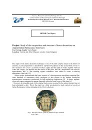
1- Study of the painting technique of Johann Baptist Lampi, father and son, at the Moravian Gallery in<br />
Brno (CZ). Acronym: LAMPI. Project leader: D. Hradil.<br />
2- Romanian illuminated medieval manuscripts in Putna: materials and techniques<br />
Acronym: PUTNA. Project leader: M. Lupu<br />
3- Non-invasive analysis of materials from paintings by Paul Cezanne in the Courtauld Institute<br />
Gallery, London. Acronym: CEZANNE. Project leader: Aviva Burnstock.<br />
4- Study of gemstones in historical jewellery at the Victoria and Albert Museum, by non-destructive<br />
techniques. Acronym: GEM. Project leader: Lucia Burgio.<br />
5- The Macclesfield Psalter & Metz Pontifical at the Fitzwilliam in Cambridge. Acronym: M&M.<br />
Project leader: Spike Bucklow.<br />
6- Analysis of polychromies and of the effects of consolidation in the stones of the façades of the<br />
Cathedral and Provincial Museum of Huesca (Spain). Acronym: SPASTONE. Project leader: Rosa<br />
Maria Esbert.<br />
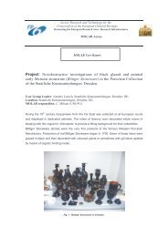
7- Paint on Early Meissen Stoneware in Dresden Museum. Acronym: POEM. Project leader: Anette<br />
Loesch.<br />
During the first six months of the <strong>second</strong> year two of these projects were carried out: the study of the<br />
painting technique of Lampi, father and son, in Brno (Czek Republic), and the study of materials of the<br />
Romanian illuminated medieval manuscripts in Putna (Romania). The works were carried out in june and<br />
september 2005. Of these two works is <strong>report</strong>ed in the website of <strong>Eu</strong>-<strong>ARTECH</strong>. In both cases the results<br />
permitted to achieve significant conclusions on the execution techniques of the examined artworks. The work<br />
on the painters Lampi (father and son) was presented by D. Hradil at the First MOLAB Users Meeting in<br />
Paris at C2RMF the 23 rd november 2005. For a <strong>report</strong> on the meeting see Annex 7.<br />
At the moment of writing the present <strong>report</strong> (december 2005) another of the planned MOLAB intervention<br />
was carried out: the project CEZANNE at the Courtauld Institute of Art Gallery in London.<br />
Further interventions will be carried out in january 2006 in London, at the V&A Museum (GEM) and at the<br />
Fitzwilliam Museum in Cambridge, UK (M&M). Other interventions have been planned during the spring<br />
2006 in Huesca, E (SPASTONE), and possibly Dresden, D (POEM).<br />
The deadline for new proposals, relative to the <strong>second</strong> semester of the <strong>second</strong> year (december 2005-may<br />
2006), was november 1 st . Nine new proposals were received. Their evaluation was carried out during the<br />
Second Interim Meeting in Paris on november 23 rd , 2005. At the PR meeting six of the presented proposals<br />
were approved. One was not recognised as eligible for MOLAB because the movement of the laboratory was<br />
not justified; the <strong>second</strong> was recognised as interesting but the planned measurements could be not adequate<br />
to solve the specific conservation problems; the third proposal was extremely interesting and very well<br />
presented but the location of the work (a site in China) requires a specific preparation and difficulties in<br />
logistics, therefore the proposers were invited to present again the proposals at the next deadline, leaving<br />
time to the PR committee and MOLAB office to evaluate the feasibility of the intervention.<br />
At the Interim Meeting in Paris, the Steering Committee evaluated as positive the activities developed.<br />
Milestones were all respected.<br />
Table: A2 - Summary of selection Panel activities during the <strong>report</strong>ing period (MOLAB PRC)<br />
Date<br />
Selection<br />
meetings<br />
Location<br />
Projects<br />
N° & Countries<br />
Submitted Selected<br />
Nov 2005<br />
4 rth MOLAB-PRC<br />
Meeting<br />
Paris 9<br />
Germany[1], United Kingdom<br />
[2], Bulgaria [1], Portugal [2],<br />
Greece [1], Turkey [1], Italy [1]<br />
6<br />
16
1.4.2.3 Meetings and workshops<br />
A joint meeting INOA-UNIPG-OPD and CNR-ICVBC was held in Florence during the “COST and Cultural<br />
Heritage” meeting (october 2005). The logistic organisation of the planned MOLAB interventions was<br />
discussed among partners and a defined calendar was established, according to the decisions of the MOLAB<br />
PR Committee.<br />
At the Florence COST meeting, B.Brunetti presented as invited speaker the talk “Transnational Access in<br />
Cultural Heritage: the case of <strong>Eu</strong>-<strong>ARTECH</strong>”, where both MOLAB and AGLAE TA activities were<br />
presented.<br />
L. Pezzati (INOA) participated, as invited speaker, to the conference LACONA VI in Vienna, presenting the<br />
talk “MOLAB: a mobile laboratory for in-situ non-invasive studies in arts and archaeology”.<br />
The First AGLAE and MOLAB Users Meeting was organised by <strong>Eu</strong>-<strong>ARTECH</strong> in May 2005 and held in<br />
Paris, at the Louvre Pavilion (C2RMF). The morning was dedicated to the presentations of the work<br />
developed by AGLAE users, while the afternoon was dedicated to the MOLAB Users. The meeting had a<br />
large participation, including potential users (see Annex 7 ). After a general presentation of C. Miliani on the<br />
more recent acquisitions and improvement of performances of MOLAB, Luke Syson (National Gallery,<br />
London), Bruno Mottin (C2RMF, Paris), Lucia Burgio (V&A Museum, London), D. Hradil (Academy of<br />
Science, Prague – Moravian Gallery, Brno), and Sophia Sotiropoulou (as substitute of Demetra Papanikola-<br />
Bakirtzis) presented the work developed through the MOLAB facility. The meeting was also the occasion for<br />
the users to meet each other and to discuss not only the scientific aspects of the work, but also to evaluate the<br />
MOLAB intervention together with the users.<br />
Suggestions about the improvement of the website were done, especially regarding the communication of the<br />
evaluations of the PR Committee. All the users declared their satisfaction for the opportunities offered by<br />
MOLAB, expressing the intention to present further proposals in the future.<br />
17
1.5 Joint research activities<br />
The continuation of both the two <strong>Eu</strong>-<strong>ARTECH</strong> JR activities was foreseen. As explained in the previous<br />
<strong>report</strong>s, JRA1-Development and evaluation of new treatments for the conservation-restoration of outdoor<br />
stone and bronze monuments has the objective to clarify and define advantages and limits of new<br />
conservative treatments on outdoor monuments, comparing new and traditional methods. The <strong>second</strong> joint<br />
research activity, JRA2-New methods in diagnostics: Imaging and spectroscopy is dedicated to the<br />
development of new methodologies in diagnostics and monitoring, setting-up innovative instrumentation for<br />
in-situ non-invasive and non-contact measurements.<br />
1.5.1 JRA1- Development and evaluation of new treatments for the conservation-restoration<br />
of outdoor stone and bronze monuments<br />
The planned work for the first six month of the <strong>second</strong> year was concerned with the partial development of<br />
Task2-Development of new treatments and procedures-chemical process and application prococols (resp.<br />
UNIPG) and Task3-Accelerated ageing of samples-stone and bronzes (resp. LNEC). The work was developed<br />
according to the planned schedule and milestones were all achieved. A Report on the developed activities is<br />
in Annex 8.<br />
Participants are CNR-ICVBC, UNI-PG, UNI-BO, BLFD, LNEC and OPD.<br />
1.5.1.1 Activity progress<br />
The definition of the drilling parameters for testing Ançã and Lecce stones was set within the scope of Task<br />
1, finished in the middle of the 1st year. However, during the <strong>report</strong>ing period, some complementary work<br />
was carried aiming at improving the drilling conditions, taking advantage of new innovative developments<br />
introduced in this testing tool. The conditions addressed were: drying of specimens; drilling speed; use of a<br />
pilot-hole and dust extraction. The new results pointed out the importance of using dried specimens and the<br />
benefit of using the pilot hole drilling technique with dust suction. Although the hole-over-hole drilling<br />
technique significantly lowered the range of forces in Ançã and Lecce stones, the discrimination of any<br />
subtle differences (such as a consolidation action) is assured by the increased reliability and precision of the<br />
data obtained with the new technique. The new drilling conditions adopted on the basis of the results are<br />
<strong>report</strong>ed in the Summary <strong>report</strong> of Annex 8.<br />
Task 2- For the study of the chemical processes and identification of the critical parameters of the treatment,<br />
a study was carried out by UNI-PG on the kinectic aspects of artificial oxalate formation on carbonatic<br />
stones and sandstones, compared to ethylsilicate in two treatments (TEOS and TEOS + coupling). For the<br />
applied conditions, the kinetic study indicated that a plateau in quantity of oxalate is obtained after 48 hours.<br />
Among the various stones, marble is producing the highest quantity, followed by limestones and sandstones.<br />
The same comparisons of oxalate treatments with TEOS and TEOS+coupling treatments were carried out on<br />
limestones by LNEC. Two different types of treatments (immersion and poulticing) with ammonium oxalate<br />
were tested, monitoring relevant parameters such as colour variation, water absorption, and drilling<br />
resistance.<br />
ICVBC, studied treatments by Ba(OH)2 in different conditions, monitoring performances, in terms of colour,<br />
quantity of product, water absorption, etc. Finally, OPD carried out a study on the influence of salt<br />
contamination in the treatments.<br />
Task 3- Tests on ageing procedures of marble by thermal shock (ICVBC) and of sandstone either with<br />
thermal shock and salt contamintaion ( LNEC) were also carried out.<br />
The results of all these studies are <strong>report</strong>ed in Annex 8.<br />
Analogous advances of the work were carried out on T2 and T3 for bronzes by UNIBO, BLFD, and LNEC.<br />
Details on this activity are again in Annex 8.<br />
18
1.5.1.2 Meetings and workshops<br />
A general working meeting has been held, with all the participating researchers (representatives from CNR-<br />
ICVBC, LNEC, UNIPG, OPD, BLFD, UNIBO), during the <strong>Eu</strong>-<strong>ARTECH</strong> meeting in Paris, November 22 nd<br />
2005. During the meeting the developed activities have ben discussed and coordination plans on future<br />
activities established.<br />
The developed work has been presented at the following conferences:<br />
- “Scienza e Beni Culturali” XXI International Congress in Brixen (I), 12-15 Jul 2005;<br />
- 14 th Triennial ICOM-CC Meeting, The Hague, NL, September 2005.<br />
- 9th Congress on Environment and Cultural Heritage Chemistry, Bologna-Rimini, Italy, 8-9 Sept<br />
2005<br />
- the 3 rd Congress of the Italian Group IIC “Lo Stato dell’Arte” Palermo, 22-24 Sept 2005;<br />
1.5.2 JRA2- New methods in diagnostics: Imaging and spectroscopy<br />
By this activity, four different new analytical methodologies for artwork studies are developed, assembling<br />
in parallel four new portable equipments for in-situ non destructive measurements.<br />
In Task1, new applications of NMR techniques to artwork studies are foreseen, included the application of<br />
the portable NMR-MOUSE; in Task2, two different and complementary methods for imaging spectroscopy<br />
in the near IR are set-up: high resolution imaging at various fixed wavelengths, with low wavelength<br />
resolution, and low resolution imaging at continuous wavelengths, with high wavelength resolution; in<br />
Task3, a new method is developed and experimented for in-situ X-ray diffraction (XRD) and X-ray<br />
fluorescence measurements (XRF); in Task4, an existing portable micro-Raman technique is joint with the<br />
VIS micro-fluorescence technique for the identification of organic colorants.<br />
1.5.2.1 Activity progress<br />
Task 1 -Application and development of laboratory analytical NMR methods and of protable NMR-MOUSE.<br />
Subtask 1.1 (UNIPG, RWTH) The study of the behaviour of clay as a function of temperature continued<br />
with the writing of a paper that has been published on Journal of Physical Chemistry. Further measurements<br />
have been carried out on new clay samples. Measurements are in progress.<br />
Subtask 1.2 (UNIPG, RWTH) A study has been started on the NMR determination of water content in stones<br />
measuring spin-lattice (T1) and spin-spin (T2) relaxation times with the objective to establish correlations of<br />
T1 and T2 with stone porosity, pore size distribution, permeability, etc. Three Umbrian stones have been<br />
chosen for the first approach: San Presto, Pianello, and Palombina Turri. Through Hahn Echo experiments<br />
the moisture content of these stones, in equilibrium with the environment, have been determined. It was<br />
found that the highest water content in normal conditions is in San Presto stone. Regarding the T1<br />
measurements, it was found that San Presto stones show the shortest T1 values. For T2 the values are<br />
comparables. Subsequent measurements were carried out on San Presto stones wetted by water capillary<br />
absorption. A clear increase in the Hahn Echo was found. In addition, an increase of T2 spin-spin relaxation<br />
time have been observed due to the increased water in the pores. (See Annex 9)<br />
Subtask 1.3 (RWTH, UNIPG) Towards the perspective of realisation of a device for the 3 D non-invasive<br />
study of painting layers an NMR sensor has been developed placed on a table that can be micrometrically<br />
moved to probe layers with a depth resolution of about 20 micrometers. No contact is necessary with the<br />
painting: once the panting and probe are aligned, the sensor is able to “explore” the material in depth.<br />
Through this new device it has been possible to carry out measurements where the thickness of paint layers,<br />
preparation, and canvas have been measured in several historical panel paintings at The National Gallery of<br />
Umbria. Among the studied painters are Gentile da Fabriano, Pietro Perugino, and Piero della Francesca.<br />
Data are in Annex 9.<br />
19
Task2-New devices for multispectral imaging of painted surfaces in the near infrared.<br />
Subtask 2.1. and 2.2 (OPD, OADC) The reference panel (standards) prepared during the first year have been<br />
characterised microscopically, through SEM picture recordings and EDS, Energy Dispersive X-ray<br />
Spectroscopy. Samples were taken out from the standards and cross sections were appropriately prepared for<br />
the study.For each examined sample, a BSE image of the cross section and EDS spectra of the various paint<br />
layers have been recorded.<br />
Other special reference samples have been prepared and spectroscopically characterised in the IR range.<br />
They have been prepared with gradually higher paint layer thickness in order to study the transmission and<br />
reflection of the IR radiation through them. These samples are painted on a common white ground and with<br />
the same binding medium in order to minimise the uncertainty of the applied algorithm during the tests.<br />
Examples of cross section images, EDS spectra at differenth depth, and IR analyses are given in Annex 9.<br />
Subtask 2.3 (OADC, INOA) Advances in the assembling of the two nIR imaging equipments have been<br />
done. In particular, in OADC a golden integration sphere has been assembled in order to permit the study of<br />
reflection and integration of the IR radiation from 800 nm up to 4500 nm. Details of the design of the<br />
integration sphere are in the Annex 9.<br />
On the other side, INOA provided to better establish a new set of cost-effective IR detectors, to design and<br />
realise the filter holders, the sub-rack unit, and the first proptotype of 16 fiber bundle. In this case, 14 Vis-<br />
NIR and 2 UV-Vis multi-mode optical fibers were used, with a cladding diameter of 230 microns. In order to<br />
properly align the 16 fibers in a square-shaped bundle, a 1 mm grove was dig.<br />
Task 3. A new device for in-situ XRD and XRF measurements.<br />
Continuing the task for the determination of the optimal conditions for XRF and XRD in-situ measurements,<br />
the Energy Dispersive X-ray Diffraction (ED-XRD) was already ruled out based on literature survey.<br />
However, during this period diffraction experiments were carreied ou to verify performances of ED-XRD<br />
with the traditional angular detection. Few different specimen were analysed: polycristalline silicon, quartz,<br />
calcite, and calcite covered by a thin layer of goethite. The measurements were carried out at 2 or 3 different<br />
2-Theta angles for each sample (this resulted in a shift of the energy peak positions). A significant case was<br />
that of polycristalline Si, because its fluorescence peaks are in the low energy range, in this way the<br />
diffraction peaks interfer only with the Cu signal due to the anode of the X-ray tube. For the other samples,<br />
the overlapping of fuorescence and diffraction can represent a strong difficulty in the spectra interpretation.<br />
Due to this overlap, the technique was confirmed not suitable for mineral identification with a portable<br />
instrument. Moreover fluorescence peaks are usually much more intense than diffraction ones. Another<br />
problem is that the diffraction peak intensity is not only weak, but also is quite large, due to the detector<br />
energy resolution and to the superposition of different diffractions. In principle these problems could be<br />
overcome by systematically doing measurements at several different angles. This could be done in a<br />
relatively quick measurement time by using a multi-element detector or some single detectors located at<br />
different 2θ angles. Indeed this solution could be appropriate, but it requires a complex and heavy equipment<br />
(not easily portable!) and also a non-trivial data analysis.<br />
In conclusion, the initial idea, based on the literature, to rule out the ED-XRD for the planned portable<br />
system was widely confirmed.<br />
In a <strong>second</strong> phase, X-ray diffraction using an “imaging plate” detection was experimented. Test<br />
measurements have been performed at the Laboratoire de Cristallographie (CNRS UPR 5031) in Grenoble.<br />
The source used was a Philips C-Tech type x-ray tube, with Cu anode and a maximum power of 2200 W (60<br />
kV). The x-ray beam was monochromatic by means of two mirrors: only Kα1, Kα2 and Kβ appear in the<br />
spectrum (with approximately the following ratio between intensities Kα/Kβ≈10 -3 ÷10 -4 ). The divergence of<br />
the beam was approximately 0.05° and its dimension was around 1.5mm x 1mm in the centre of the<br />
goniometer, with a flux of around 10 7 ph/s. The tube was biased at 50 kV and 40 mA.<br />
For each investigated sample two XRD detector systems have been used:<br />
- a conventional scintillator detector, with a monochromator in front of it, in a θ-2θ configuration<br />
- an Imaging Plate (IP) perpendicular to the incident X-ray beam at distance of around 20 cm from<br />
sample.<br />
The Imaging Plate detector proved to be a valid alternative to the one-dimensional scintillator detector: the<br />
measurement times are comparable (around 20÷30 minutes for both), even if Imaging Plate seems to be more<br />
efficient. Imaging Plates have the big advantage of being a two-dimensional low-noise system, with a<br />
flexible and wireless mounting, and they allow to collect data in a parallel detection configuration. On the<br />
20
other hand the scanner system requires around 3 minutes to read the recorded image (it is not an online<br />
measurement; the result is visible only at the end of the process) and Imaging Plates are light sensitive<br />
(Annex 9).<br />
Task 4 – A joint micro-Raman and micro-fluorimeter new portable apparatus.<br />
The vibrational and electronic characterisation of dyestuffs and lakes was continued largely increasing the<br />
microRaman and UV-VIS fluorescence database of solid powder standard dyes and lakes.<br />
Standard materials have been examined employing micro-Raman in the lab set-up using two excitation<br />
wavelength 532 nm and 785 nm. The portable set-up has been experience as micro-Raman using the 532nm<br />
excitation and as fluorimeter using again the 532nm excitation, but conveniently moving the polychromator.<br />
MicroRaman and fluorescence spectra are <strong>report</strong>ed in the database format in Annex 9. Interestingly, the<br />
portable equipment has been proven to be well set-up for the study of red anthraquinone dyes, in fact in this<br />
case using the 532 nm excitation it is observed a resonance enhancement and a relatively low fluorescence<br />
background thanks to a large Stoke shift.<br />
1.5.2.2 Meetings and workshops<br />
A general working meeting has been held with all the participating researchers (representatives of UNIPG,<br />
RWTH, INOA, OADC, and C2RMF) during the <strong>Eu</strong>-<strong>ARTECH</strong> meeting in Paris, november 2005.<br />
A bilateral meting RWTH and UNIPG was held in Perugia, from July 17 th to 22 nd (J.Perlo, RWTH;<br />
F.Presciutti, B.Brunetti, A.Sgamellotti, UNIPG). The meeting was dedicated to discuss details of the portable<br />
NMR depth-profile device. Improvements were introduced and measurements were carried out at the<br />
National Gallery of Umbria. A <strong>report</strong> on these measurements is in the Annex 9.<br />
Another working meeting on the NMR depth-profile was held in Perugia, in the evening of july 20 th , at the<br />
end of the NMR School on portable NMR in Cultural Heritage. Participants were: B. Bluemich, F.Casanova,<br />
and J.Perlo, RWTH, and F.Presciutti, B.Brunetti , and A.Sgamellotti, UNIPG. During these meeting the<br />
results obtained in the lab-study on water content in Umbrian stones were examined and discussed. A plan of<br />
new measurements was also done.<br />
21
2. LIST OF DELIVERABLES<br />
Activity<br />
N1<br />
Deliv<br />
No<br />
Deliverable Name Task No Delivered by<br />
Contractor<br />
1 REPORT ON THE STANDARDISED FORMAT<br />
FOR DESCRIBING ANALYTICAL<br />
PROCEDURES.<br />
2 REPORT ON INTERLABORATORY<br />
COMPARISON<br />
3 REPORT ON OVERVIEW ON POSSIBLE<br />
SHARING OF REFERENCE MATERIALS<br />
4 REPORT ON THE NMR WORKSHOP (CD<br />
ON PRESENTATIONS)<br />
Task 1c<br />
Task 1b<br />
OADC, ICN, NGL,<br />
IRPA,OPD,ICVBC,<br />
UNIPG,UNIBO,<br />
C2RMF, LNEC,<br />
BLFD<br />
OADC, ICN, NGL,<br />
IRPA,OPD,ICVBC,<br />
UNIPG, C2RMF,<br />
LNEC, BLFD,<br />
UNIBO<br />
Task 2a ICN, NGL, IRPA,<br />
OADC, UNIPG,<br />
Task 2c UNIPG, RWRTH,<br />
NGL, OPD<br />
OADC<br />
Plan<br />
ned<br />
(imon<br />
ths)<br />
Achieved<br />
(months)<br />
18 18<br />
[Annex 4 ]<br />
18 18<br />
[this <strong>report</strong><br />
and Annex 4]<br />
18 18<br />
[this <strong>report</strong>,<br />
pages 7-8]<br />
18 18<br />
[Annex 5 ]<br />
5 REPORT ON THE GUPIX COURSE Task 2c C2RMF 18 18<br />
[Annex 6 ]<br />
N2 6 MULTI LANGUAGE FORMS<br />
Task 1d CNR-ICVBC, OPD,<br />
IRPA,ICN,LNEC,<br />
UNIPG, C2RMF,<br />
BLFD,NGL, UNIBO,<br />
OADC<br />
18 18<br />
[see website;<br />
res.area]<br />
7 DATABASE FOR THE ANALYSIS OF<br />
RESULTS OF THE SURVEY ACTION<br />
Task 1d CNR-ICVBC, OPD 18 18<br />
[see website;<br />
res.area]<br />
8 REPORT ON THE SURVEY ACTION AT<br />
ICOM-CC<br />
Task 1d CNR-ICVBC, ICN,<br />
UNIPG, C2RMF<br />
IRPA, OPD, OADC<br />
18 18<br />
[this <strong>report</strong><br />
and website]<br />
9 SET UP OF A LIST OF CONSERVATORS Task 1d CNR-ICVBC, OPD, 18 18<br />
IRPA,ICN,LNEC,<br />
UNIPG, C2RMF,<br />
BLFD,NGL, UNIBO,<br />
[for the list,<br />
see website;<br />
res.area]<br />
TA1 10 SUMMARY REPORT ON AGLAE<br />
11 1 ST<br />
USERS’ MEETING REPORT C2RMF,<br />
UNIPG,INOA,CNR-<br />
TA2 12 SUMMARY REPORT ON MOLAB<br />
C2RMF 18 18<br />
[this <strong>report</strong>,<br />
ICVBC,OPD<br />
UNI-PG, INOA,<br />
CNR-ICVBC, OPD<br />
13 1 ST<br />
USERS’ MEETING REPORT C2RMF,<br />
UNIPG,INOA,CNR-<br />
JRA1 14 PROGRESS REPORT ON THE<br />
PROCEDURES TO BE ADOPTED FOR EACH<br />
TREATMENT UNDER STUDY<br />
15 PROGRESS REPORT ON THE<br />
CHARACTERISTICS OF THE SAMPLES<br />
JRA2 16<br />
(STONE AND BRONZE) DURING AGEING<br />
PROCEDURES<br />
PROGRESS REPORT ON LAB NMR AND<br />
METHODOLOGY FOR IN-SITU STUDY OF<br />
WATER-RELATED PROPERTIES OF STONE<br />
Task 2<br />
ICVBC,OPD<br />
CNR-ICVBC,UNIPG,<br />
BLFD,OPD, and<br />
participating partners<br />
pages 13-15]<br />
18 18<br />
[Annex 7 ]<br />
18 18<br />
[this <strong>report</strong>,<br />
pages 15-17]<br />
18 18<br />
[Annex 7]<br />
18 18<br />
[Annex 8]<br />
Task 3 UNIBO, BLFD,LNEC 18 18<br />
[Annex 8]<br />
Task1-<br />
Subtask<br />
1.1<br />
UNI-PG,RWTH 18 18<br />
[Annex 9]<br />
22
17 PROGRESS REPORT ON NMR MOUSE<br />
3D<br />
18 PROGRESS REPORT ON MICRO- AND<br />
SPECTROSCOPIC CHARACTERISATION OF<br />
STANDARDS.<br />
19 REPORT ON OPTIMAL CONDITIONS FOR<br />
ARTWORK XRD STUDIES AND ON<br />
XRD&XRF SYSTEM DESIGN AND<br />
ASSEMBLING.<br />
20 REPORT ON THE SPECTROSCOPIC<br />
CHARACTERISATION OF THE PREPARED<br />
SAMPLES.<br />
Task 1-<br />
Subtask<br />
1.3<br />
RWTH , UNIPG 18 18<br />
[Annex 9]<br />
Task2- INOA, OADC 18 18<br />
[Annex 9]<br />
Task3-<br />
Subtask<br />
1<br />
Task4-<br />
Subtask<br />
1<br />
CNRS-C2RMF 18 18<br />
[Annex 9]<br />
UNIPG 18 18<br />
[Annex 9]<br />
23
3. USE AND DISSEMINATION OF KNOWLEDGE<br />
Dissemination has been carried out through all the media that are commonly available to contact potential<br />
users (that are identified as conservation scientists, conservator, restorers, libraries, museums, schools on<br />
conservation, cultural institutions, etc.) but also public. Indeed, conservation of cultural heritage has strong<br />
societal implications and it is of general interest for the public and policy makers. Used media have been:<br />
internet, e-mail, conferences, contacts with other organisations, and, in some cases, press.<br />
The <strong>Eu</strong>-<strong>ARTECH</strong> website (www.eu-artech.org) was continuosly adjourned, introducing new pages and links<br />
in the effort to create an easily readable interface with institutions internal and external to the Consortium,<br />
potential users, and public. A specific restricted area, accessible only by password, was reserved to the<br />
exchange and diffusion of working documents.<br />
A list of relevant websites of interest in the conservation science and conservation/restoration of cultural<br />
heritage was also established and made accessible in the website.<br />
A specific relevance was given to the AGLAE and MOLAB Transational Access starting from the home<br />
page. Information is also available on the projects already developed, through the Users Report on-line e<br />
picture documentation.<br />
Relevance is also given to the events, open to potential users and public, organised or promoted by <strong>Eu</strong>-<br />
<strong>ARTECH</strong> such as workshops, schools, conferences and meetings.<br />
The website has been built as the more friendly interface between the Consortium and the community of<br />
conservation scientists, conservators, restorers, scholars, as well as funding agencies and policy makers.<br />
The effort on establishing fruitful interactions among <strong>Eu</strong>-<strong>ARTECH</strong> and relevant infrastructures in the field<br />
of cultural heritage had no stop. On this type of dissemination of knowledge has been given large space ib<br />
the networking N1 section of this <strong>report</strong>.<br />
Other diffusion or dissemination of knowledge was carried out through plenary lectures, invited conferences,<br />
seminars, or presentations of <strong>Eu</strong>-<strong>ARTECH</strong> programs and initiatives in relevant international and national<br />
congresses and meetings, such as:<br />
- “COST and Cultural Heritage: crossing borders” – Florence – October 20-22 2005<br />
(http://www.echn.net/cost-hig/florence2005) a <strong>Eu</strong>ropean meeting where the COST activities of the field have<br />
been discussed in the perspective of future developments. During this meeting, <strong>Eu</strong>-<strong>ARTECH</strong> had a large<br />
evidence. The Coordinator gave the lecture: “Transnational Access in Cultural heritage: the case of <strong>Eu</strong>-<br />
<strong>ARTECH</strong>”.<br />
- “3rd International conference on the application of Raman spectroscopy in art & archaeology”– Paris - 31<br />
August - 3 September 2005<br />
-“MODHT end-of-project meeting” on 20th-21st June. (Monitoring of Damage in Historic Textiles).<br />
- “29 th International Symposium on High Performance Liquid Phase Separations and Related Techniques”,<br />
26-30 June 2005, Stockholm, Sweden<br />
-“MaSC Users Group”, 7-10 September 2005, Van Gogh Museum, Amsterdam.<br />
-“Dyes in History and Archaeology annual meeting, DHA 24”, in Liverpool, 3-5 November 2005.<br />
- “14th ICOM-CC Triennial Meeting” - The Hague - 12-16 September 2005.<br />
Contacts have been consolidated with organisations developing activities in the same field or of interest in<br />
the field, such as:<br />
- I3 initiatives, such as LASERLAB (http://www.laserlab-europe.net/index.html) , NMI3<br />
(http://neutron.neutron-eu.net/n_nmi3), and IA-SFS (http://www.elettra.trieste.it/i3/), also working in the<br />
field of cultural heritage;<br />
- infrastructures operating in the field, such as the ICTP (Abdus Salam International Centre for Theoretical<br />
Physics of Trieste, http://www.ictp.it/ ) or the LABEC – INFN of Florence (http://labec.fi.infn.it/index.html);<br />
- EC projects, such as COST G8 (http://srs.dl.ac.uk/arch/cost-g8/index.htm), COST G7<br />
(http://alpha1.infim.ro/cost/pagini/home.html), CEN/TC 346 (http://www.cenorm.be/CENORM/index.htm)<br />
dedicated to the “Conservation of Cultural Property;<br />
24
- ICOM-CC (http://icom-cc.icom.museum/) or IIC (http://www.iiconservation.org/index.php);<br />
- Marie-Curie actions, such as ATHENA and EPISCON<br />
(http://www.scienze.unibo.it/Scienze+Matematiche/Post+Laurea/Altri+corsi+post+laurea/episcon.htm), a<br />
<strong>Eu</strong>ropean PhD in Science for Conservation.<br />
Regarding the press, <strong>Eu</strong>-<strong>ARTECH</strong> activities were disseminated in occasion of the press release, organised by<br />
the National Gallery of London on the work developed, through MOLAB, on the “Vergin of the Rocks” of<br />
Leonardo. The new had a <strong>Eu</strong>ropean relevance.<br />
25
Annex 1<br />
ANNEXES<br />
Summary Report of the Second Interim Meeting<br />
Paris, november 21 st -22 nd 2005 – Pavilion du Louvre- C2RMF<br />
The meeting was helsd in the rooms of the C2RMF with participants from all the Consortium institutions.<br />
The following people was present:<br />
Nathalie Balcar C2RMF, Bernhard Blümich RWTH, Eliane Bohnert C2RMF, David Bourgarit C2RMF, Jean<br />
Louis Boutaine C2RMF, Susanna Bracci CNR-ICVBC, Brunetto Giovanni Brunetti UNIPG, Laura<br />
Cartechini UNIPG, Jacques Castaing C2RMF, Nathalie Collain CNRS, José Delgado Rodrigues LNEC,<br />
Maria Douka CEE, Ana Paula Ferreira Pinto Instituto Superior Técnico (IST), Alessandra Gianoncelli<br />
C2RMF, Ineke Joosten ICN, Mathias Kocher BLFD, Christian Lahanier C2RMF, Anne-Solenn Le Hô<br />
C2RMF, Martin Mach BLFD, Francine Mariani-Ducray Direction des Musées de France, Vincent Mazel<br />
C2RMF, Rocco Mazzeo UNIBO, Michel Menu C2RMF, Costanza Miliani UNIPG, João Mimoso LNEC,<br />
Christiane Naffah C2RMF, Cristiana Nunes LNEC, Sandrine Pagès C2RMF, Juan Perlo RWTH, Luca<br />
Pezzati INOA, Daniela Pinna OPD, Martine Regert C2RMF, Pascale Richardin C2RMF, Dominique Robcis<br />
C2RMF, Stefan Röhrs C2RMF, Ashok Roy NGL, Barbara Sacchi CNR – ICVBC, Barbara Salvadori OPD,<br />
Manfred Schreiner Academy of Fine Arts Wien, Antonio Sgamellotti UNIPG, Sophia Sotiropoulou OADC,<br />
Marika Spring NGL, Olivier Tavoso C2RMF, Lucia Toniolo CNR – ICVBC, Stéphane Vaiedelich Musée de<br />
la musique de Paris, Maarten Van Bommel ICN, Elsa Van Elslande C2RMF, Ina Vanden Berghe KIK –<br />
IRPA, Jan Wouters KIK – IRPA.<br />
The meeting started with the introductory notes of the new Director of C2RMF, Dr. Christiane Naffah, who<br />
presented herself to the Consortium and welcomed all participants.<br />
After a general review by M. Menu (C2RMF) of the planned two days work, the Coordinator B.G. Brunetti<br />
opened the formal meeting presenting the main line of the <strong>Eu</strong>-<strong>ARTECH</strong> dissemination of knowledge during<br />
the period June-November 2005. He mentioned the Schools and Meetings sponsored or directly organized by<br />
<strong>Eu</strong>-<strong>ARTECH</strong>, such as<br />
-the “3 rd International Conference on the application of Raman spectroscopy in Art and Archaeology” (Paris<br />
F, Aug 31-Sept 3,2005);<br />
-the Workshop on Non-invasive NMR in Cultural Heritage and NMR Colloqium (Perugia, I, Sept 19-23,<br />
2005);<br />
-the GUPIX School (Paris, Oct 6-7, 2005).<br />
B.Brunetti dedicated particular attention to the description of the presence of <strong>Eu</strong>-<strong>ARTECH</strong> at the Triennial<br />
Meeting of ICOM-CC (The Hague, NL, September 2005).<br />
Dr. Maria Douka of the R.I. Office of the EC, presented the perspectives of evolution of Research<br />
Infrastructures towards the 7 th Framework Programme. Great attention of the odeon was achieved during the<br />
discussion of the activities of ESFRI and the perspectives of creation of the ERA in the field.<br />
I - Consortium Governing Board n. 4<br />
After a short break, the fourth <strong>Eu</strong>-<strong>ARTECH</strong> Consortium Governing Board was held. According to the<br />
Consortium Agreement, this meeting was restricted to the Coordinator and one authorised representative for<br />
each participant infrastructure.<br />
The following representatives were present: Coordinator: B.Brunetti; UNIPG: A. Sgamellotti; CNRS-<br />
C2RMF: M.Menu; CNR-ICVBC: S.Bracci; NGL: A. Roy; OPD: D. Pinna; BLFD: M. Mach; OADC: S.<br />
26
Sotiropoulou; ICN: M. Bommel; LNEC: J. Delgado; IRPA: J. Wouters; RWTH: B. Bluemich; UNIBO: R.<br />
Mazzeo; INOA: L. Pezzati.<br />
1- Amendments to the contract<br />
The Coordinator announced that from June 1 st INOA formally merged into CNR, however it was authorised<br />
to maintain its administrative rules, being entered in a transitory phase. The GB decided to ask to the EC R.I.<br />
office if the change of model cost from AC (cost model of INOA in the contract) to FC (the cost model of<br />
CNR) is obligatory or can be postponed up to the end of the transitory phase. In case of obligation, the<br />
request of amendment of the contract is to be considered authorised by the GB.<br />
B. Brunetti illustrated the content of the clause 39 that could be introduced in the contract. It allows<br />
institutions having an annual budget lower than 150.000 euros to skip the audit. Specifically, clause 39 says:<br />
“Nothwithstanding the provision of article 7.2 of this contract, contracors requesting a EC financial<br />
contribution for one or more <strong>report</strong>ing periods of less than 150.000 euros, need not to submit an audit<br />
certificate, until the comulative request for EC financialcontribution is equal or exceeds 150.000 euros for<br />
the <strong>report</strong>ingperiods for which an audit certificate has not yet been submitted.In all cases an audit certificate<br />
shall be submitted at the latest 45days after the final <strong>report</strong>ing period. This final audit will cover all the<br />
periods for which an audit certificate has not been previously submitted.”<br />
The Coordinator presented and discussed advantages and possible inconvenients of the introduction of clause<br />
39. After accurate evaluation by the Consortium representatives, it was decided to renounce to clause 39 and<br />
accept the rule of presenting every year the Audit Certificate for each institution.<br />
As a third point, the possible extension of RWTH participation to <strong>Eu</strong>-<strong>ARTECH</strong> was discussed. The original<br />
formulation of the contract includes a participation of RWTH limited to the first two years. However, RWTH<br />
is developing a relevant work on new NMR methodologies for the laboratory and in-situ studies of artworks;<br />
therefore, it would be important for <strong>Eu</strong>-<strong>ARTECH</strong> to extend its participation, at least, for another year. All the<br />
partners agreed on this point. In order to allow RWTH to continue its activity, the Coordinator proposed to<br />
shift part of the UNIPG budget (corresponding to an amount of 25.000 euros) to RWTH. Unanimously, the<br />
GB accepted the proposal of the Coordinator inviting him to proceed to the request of amendment of the<br />
contract.<br />
The Coordinator communicated that the Bank of UNIPG changed its coordinates. The change was due to the<br />
merging of the Banca dell’Umbria into the largest UniCredit Banca. The new coordinates will be<br />
communicated to the EC asking for the relative amendment of the contract. All GB members agreed with the<br />
request of amendment. The new name of the Bank is: UniCredit Banca; the new IBAN:<br />
IT58G0200803016000029489728.<br />
2- Administrative notes<br />
The Coordinator informed the Consortium member representatives that the procedure to close the First<br />
Annual Report with the inclusion of the Audit Certificates of all the participating institutions was not yet<br />
ended. However, all the documentation should be ready in few days.<br />
In any case, due to the strong foreseen delay in the pre-financing of the <strong>second</strong> year, the Coordinator<br />
announced to reserve to himself the use of the residue of the budget of the First Year, not yet distributed to<br />
the partners, for a pre- prefinancing of those institutions (only) that spended all (or almost all) their first year<br />
budget.<br />
The assembly was favourable.<br />
3- Next Annual Meetings<br />
At the end of the GB meeting the proposal of Munchen as location for the Third Year Annual Meeting was<br />
advanced by M. Mach of BLFD. The proposal was unanimously accepted.<br />
The National Gallery of London, as possible site for the Third Year Interim Meeting was also proposed and<br />
accepted.<br />
Therefore the locations of the next <strong>Eu</strong>-<strong>ARTECH</strong> meetings is the following:<br />
-Second Year Annual Meeting – Lisbon, LNEC, May 3-5 2006;<br />
-Third Year Interim Meeting – London, NGL, date to be established;<br />
-Third Year Annual Meeting, Munchen, BLFD, date to be established.<br />
27
4- Note<br />
It has been proposed by LNEC and accepted by GB, to define and publish on the <strong>Eu</strong>-<strong>ARTECH</strong> website a list<br />
of trainees & training opportunities “stock exchange” among the participating institutions. Such a simple and<br />
flexible item will permit to increase and diversify the training possibilities in the areas of the project. No <strong>Eu</strong>-<br />
<strong>ARTECH</strong> funding will be involved. Institutions and/or trainees will manage by themselves to find the<br />
necessary financing.<br />
With this last decision, the Governing Board meeting was closed.<br />
II- Networking N1 and N2 Joint Activities.<br />
After the lunch break, the meeting continued with the discussion of the networking activities N1 and N2.<br />
Rocco Mazzeo (UNIBO) briefly presented the project EPISCON (<strong>Eu</strong>ropean PhD in Science for<br />
Conservation), a Marie Curie Early Stage Training fellowships of the 6th Framework Programme, recently<br />
approved.<br />
J.L.Boutaine, the Convenor of N1 introduced the discussion of N1 activities.<br />
N1 networking specific activities of the first six months of the <strong>second</strong> year consisted mainly in the<br />
continuation of Task 1 on Analytical resources, analytical procedures and investigation strategies,<br />
especially referred to organic substance investigations and the start of Task 2- Exchange knowledge and<br />
expertise. Within Task 1 the continuation of dissemination of <strong>Eu</strong>-<strong>ARTECH</strong> activities on analytical<br />
investigations of artwork materials was also planned (with particular reference to examination of paintings).<br />
Discussions followed where all the activities developed in the various tasks and subtasks were presented.<br />
Lucia Toniolo introduced then the discussion on N2. The problems related to the translation of the survey<br />
forms were discussed and the data base structure for the analysis of results of the survey was presented. It<br />
was also presented the diffusion of the survey action at the ICOM-CC meeting (a specific association of<br />
conservators and conservation scientists), where it was started the set-up of a list of conservators interested to<br />
participate to the survey.<br />
III- Transnational Access Activities<br />
M.Menu, C2RMF, shortly presented the AGLAE access activity of the first six months of the <strong>second</strong> year.<br />
Immediately after, C.Miliani, , UNIPG, did the same for the MOLAB activities. The presentation was limited<br />
to few information on the proposals received (10 for AGLAE and 9 for MOLAB) because a wider<br />
discussion on Transantional Access is forseen for the day of November 23 rd , where the First Users Meeting<br />
of AGLAE and MOLAB will be held.<br />
At the end of the first day, a social dinner was held at the Restaurat “Gran Louvre” inside the Museum.<br />
According to the Agenda, the morning of tuesday 22 nd , the meeting started with the presentation of the Joint<br />
Research activities.<br />
IV – Joint Research Activities.<br />
Regarding JRA1, under the coordination of S. Bracci, ICVBC, kinectic aspects of artificial oxalate formation<br />
on carbonatic stones and sandstones compared to ethylsilicate in two treatments (TEOS and TEOS +<br />
coupling) were presented by C. Miliani, UNIPG. The same comparisons of oxalate treatments with TEOS<br />
and TEOS+coupling was carried out on limestones by LNEC (J. Delgado). S. Bracci, ICVBC, described<br />
results obtained in treatments by Ba(OH)2 in different conditions (verification of performances, in terms of<br />
colour, quantity of product, water absorption, etc).<br />
Tests on ageing procedures of marble by thermal shock and of sandstone either with thermal shock and salt<br />
contamintaion were also presented. Finally, OPD (D.Pinna) presented results on treatments by oxalate and<br />
procedures for contamination by salts.<br />
28
Analogous advances of the work were discussed for bronzes by R.Mazzeo, UNIBO, M. Mach, BLFD, and<br />
J.Mimoso, LNEC.<br />
In the afternoon, after the lunch break, first the results obtained on JRA2 laboratory NMR studies were<br />
presented by UNIPG. These studies led to a publication that will appear on Journal of Physical Chemistry A.<br />
The paper will concern with the structural aluminosilicate modifications during the firing of clays. The more<br />
recent results on portable NMR were also presented, regarding the performances of the NMR profilometer<br />
developed under the coordination of RWTH. Then the recent advances on the systems for IR imaging were<br />
presented by L.Pezzati, INOA, and S.Sotiropoulou, OADC. A. Gianoncelli presented the advancement in the<br />
work carried out by C2RMF in setting a new XRF and XRD equipment and, finally, A.Sgamellotti presented<br />
the more recent results for the system to carry out micro-Raman and micro-fluorescence measurements.<br />
At the end of all the presentations, the Coordinator and the Steering Committee verified that in all cases, the<br />
work had a regular development and milestones were achieved, according to the contract.<br />
Before the closure, the Coordinator briefly synthetised the work carried out during the two days of the<br />
meeting and traced the general lines of development of the work to be carried out during the following six<br />
months. Final thanks were addressed to C. Naffah, M.Menu and all C2RMF members, who took care of the<br />
excellent organisation.<br />
29
Annex 2<br />
Components of the Peer Review International Committees<br />
AGLAE<br />
MOLAB<br />
Components of the Peer Review Committee<br />
Annemie Adriaens Department of Analytical Chemistry, University of Ghent,<br />
Belgium<br />
Aurelio Climent-Font Departmento de Física Aplicada, Universidad Autónoma de<br />
Madrid, Cantoblanco, Madrid, Spain<br />
Patrick Trocellier Research Centre of Atomic Energy Commission (CEA), Saclay<br />
France<br />
Jean Claude Dran AGLAE representative<br />
Manfred Schreiner Institute of Chemistry, Academy Fine Arts, Vienna , Austria<br />
Modesto Montoto Dept. of Geology, Group of Petrophysics, University of<br />
Oviedo, Spain<br />
Marisa Tabasso Former Director of Laboratories of Istituto Centrale del<br />
Restauro and ICCROM, Rome, Italy<br />
Brunetto Giovanni MOLAB representative<br />
Brunetti<br />
30
Annex 3<br />
List of new AGLAE and MOLAB User-Projects presented and evaluated<br />
during the first six-months of the <strong>second</strong> year.<br />
AGLAE<br />
Applicant Institution Project title/number Time<br />
requested<br />
(days)<br />
R. Bertoncello University of<br />
Padova (I)<br />
A. Von Bohlen<br />
C. Luglie<br />
Study of protective sol-gel layers for<br />
ancient glass<br />
ISAS<br />
Internal standard method µPIXE to<br />
Dortmund/Germa<br />
analyze paper, parchment and wood<br />
ny<br />
University<br />
Cagliati/Italy<br />
IFIN-HH<br />
B. Constantinescu Bucarest/Romani<br />
B. Colston<br />
a<br />
Lincoln<br />
University<br />
Lincoln/UK<br />
A. Zucchiatti INFN Genoa/Italy<br />
R. Golser<br />
R. Bertoncello<br />
A. Polvorinos del<br />
Rio<br />
D. Strivay<br />
University<br />
Vienna/Austria<br />
University<br />
Padova/Italy<br />
University<br />
Sevilla/Spain<br />
<strong>Eu</strong>ropean Centre<br />
of Archaeometry<br />
Liège/Belgium<br />
Neolithisation and obsidian circulation in<br />
western Mediteranean Sea<br />
early periode of Sardinian neolithic<br />
Micro-PIXE studies on Visigothic<br />
“Pietroasa”gold hoard objects<br />
Analysis of hazardous organic and<br />
inorganic residues applied to dried<br />
botanical collections<br />
PIXE study of Morocco zelliges and<br />
mortars from the XIVth to XVIIIth<br />
centuries<br />
Damage evaluation for Micro-PIXE used<br />
for the analysis of metal point drawings<br />
Study of sol-gel protectives for ancient<br />
glass<br />
Analyses of lustered ceramics from<br />
Andalusia<br />
9<br />
Time<br />
allocated<br />
(days)<br />
Planned<br />
month<br />
5 December<br />
5 5 March<br />
4 5 February<br />
3 3 January<br />
2 2 March<br />
3 0<br />
2 2 March<br />
6 0<br />
4 4 April<br />
Study of patinas of antique bronzes 6 5 May<br />
Sum of days 47 31<br />
% total time available 38% 25%<br />
Total days available 125<br />
31
MOLAB<br />
Applicant Institution Project title/Acronym Techniques Approval<br />
Kitan<br />
Kitanov<br />
Ines Abreu<br />
Correia<br />
Bulgarian<br />
Ministry of<br />
Culture<br />
National<br />
Archives<br />
Institute- Torre<br />
do Tombo, P<br />
Isabel Ribeiro Portuguese<br />
Institute for<br />
Conservation<br />
and Restoration<br />
Nicola<br />
Spinosa<br />
Noni<br />
Maravelaki<br />
Soprintendenza<br />
Speciale per il<br />
Polo Museale di<br />
Napoli<br />
25th Ephorate of<br />
Prehistoric and<br />
Classical<br />
Antiquities,<br />
Ministry of<br />
In-situ analysis of the early<br />
Hellenistic wall painting in<br />
the Thracian tomb near the<br />
village of Alexandrovo,<br />
Bulgaria (HELLEN)<br />
Comparative<br />
characterization of two<br />
illuminated medieval codex<br />
of the 12 th century and<br />
damage assessment of the<br />
parchment support.<br />
(MEDI-COD)<br />
Casas Pintadas de Évora.<br />
(EVORACAP)<br />
Drawing and colour in<br />
designing a painting:<br />
Polidoro artwork in<br />
Capodimonte.<br />
(CAPODIMONTE)<br />
In-situ identification of the<br />
penetration depth of<br />
consolidants on bioclastic<br />
limestones through microdrilling<br />
measurements<br />
XRF, FT-IR, Vis-NIR,<br />
micro-Raman, UV-Vis<br />
fluorescence,<br />
fluorescence imaging,<br />
micro-drilling<br />
XRF, FTIR, micro-<br />
Raman, UV-Vis<br />
fluorescence,<br />
fluorescence imaging,<br />
NMR-MOUSE<br />
FT-IR, Vis-NIR, micro-<br />
Raman, IR-colour<br />
scanner, laser microprofilometry,UV-Vis<br />
fluorescence,<br />
fluorescence imaging<br />
XRF, IR-colour<br />
scanner, fluorescence<br />
imaging<br />
Notes<br />
-- Measurements<br />
could be not<br />
adequate to<br />
solve the<br />
specific<br />
conservation<br />
problems<br />
yes<br />
yes<br />
yes<br />
Micro-drilling yes<br />
Culture (KRETE)<br />
Fusun Okyar Tubitak Study of archaeological XRF, Vis-NIR, micro- -- Project not<br />
Marmara materials from Iznik: Glazes Raman<br />
Research center and colour of original Iznik<br />
materials ware. (IZNIK)<br />
institute<br />
pertinent for<br />
in-situ studies<br />
David English Heritage Investigation of Silver XRF, FTIR, Vis-NIR yes<br />
Thickett<br />
Tarnish Risk and Remaining<br />
Protection Afforded by<br />
Lacquers.(SILVER)<br />
Sharon Courtauld Non-Invasive Analysis of XRF, FT-IR, Vis-NIR, -- To be<br />
Cather Institute of Art,<br />
University of<br />
London<br />
Mural Paintings.<br />
(NIAM)<br />
micro-Raman, IRcolour<br />
scanner, UV-Vis<br />
fluorescence,<br />
fluorescence imaging,<br />
NMR-MOUSE<br />
presented at<br />
the next<br />
deadline<br />
Roberto Gemäldegalerie - A Technical Study of the XRF, FTIR, Vis-NIR, yes<br />
Contini Staatliche Paintings: Amor Vincit IR-Colour scanner,<br />
Museen zu Omnia by Caravaggio, laser microprofilometry,<br />
Berlin Portrait of a Lady (Dorotea) NMR-MOUSE<br />
and Reclining nude of a<br />
woman in a landscape<br />
(Cerere) by Sebastiano del<br />
Piombo (CARAVAGGIO)<br />
32
Annex 4<br />
I-Report on the standardised format for describing analytical procedures<br />
DELIVERABLE N.1<br />
Proposed format analytical protocol<br />
- Aim of the protocol, short description<br />
- Name of the Author<br />
- Date of latest version<br />
- Chemicals<br />
o Reagent, grade, concentration, supplier, product number<br />
- Materials (below some examples when dealing with HPLC protocols)<br />
o Column<br />
Dimension column<br />
Nature of particle<br />
Monomeric or polymeric column<br />
Particle size<br />
Particle distribution and deviation<br />
Pore diameter<br />
Surface area<br />
Total carbon %<br />
Surface coverage<br />
End capped<br />
Supplier, product number<br />
Add reference if available: What did we want with this?<br />
o Guard column → type, dimension, supplier, product number<br />
o Filters→ type, dimension, supplier, product number<br />
Reagent preparation<br />
Equipment (below some examples when dealing with HPLC protocols)<br />
o Pump<br />
o Degasser<br />
o Autosampler / injector<br />
o Column oven<br />
o Post column derivatisation system<br />
o Detector<br />
Pre-examination<br />
Sample pre-treatment<br />
Analysis<br />
- Blank analysis, what serves as a blank and how often is it done<br />
- Standards, what is used as a standard, with which purpose and how often<br />
- Detection parameters<br />
- Data evaluation<br />
- Additional field for specific comments<br />
- Show example of analysis of a standard<br />
- Add relevant literature about the analysis (if available)<br />
33
II- Interlaboratory Comparison<br />
Analytical investigation strategies on organic materials<br />
DELIVERABLE N. 3<br />
NOPART meeting, 16 September 2005, Brainstorm about Networking on Natural Organic Polymer:<br />
Identification and Alteration<br />
Present:<br />
Jo Kirby National Gallery London, UK<br />
David Saunders British Museum, UK dsaunders@thebritishmuseum.ac.uk<br />
Chris Maines National Gallery, Washington,<br />
USA<br />
c-maines@nga.gov<br />
Patrick Dieterman Bayerisches Landesamt für<br />
Denkmalpflege, Germany<br />
Patrick.dietemann@blfd.bayern.de<br />
Marianne Odlyha Birkbeck College, UK m.odlyha@bbk.ac.uk<br />
Rene Larssen School of Conservation,<br />
Denmark<br />
rl@kons.dk<br />
Anne-Laurance Dupont CRCDG, France<br />
aldupont@mnhn.fr<br />
Sophia Sotiropoulou OADC, Greece<br />
Ina Vanden Berghe KIK/IRPA, Belgium<br />
Maarten van Bommel ICN, The Netherlands<br />
Introduction by Jan Wouters:<br />
Natural organic polymers are among the main constituents of materials such as textiles, leather,<br />
parchment, paper, photographs, bone, horn, antlers, natural adhesives and binding media of paint. They are<br />
composed of cellulose and protein mainly. Their presence in cultural heritage artefacts of such diversity has<br />
resulted in the existence of object-specific research lines, as clearly expressed in a series of past and present<br />
<strong>Eu</strong>ropean research projects (Leather Project CT90-0105; Leather Project EV5V-CT94-0514; ENVIART on<br />
artificial marble; MAP and IDAP on parchment; InkCor, Papylum, ServeNIR, PaperTreat and MIP on paper;<br />
MODHT on textiles), many of them based on national research efforts. It is the main objective of this<br />
initiative to provide appropriate bridging of these.<br />
Joint meetings of researchers will focus on sample preparation, analysis procedures and parameters<br />
to calculate, in order to contribute to the material’s and the object’s damage assessment. Balances of<br />
invasiveness/destruction on the one hand and detail and wealth of analytical information on the other will be<br />
critically evaluated. Investigating how the properties of a natural organic polymer change as a function of<br />
materials added may help formulating jeopardizing conservation or treatment conditions. For example may<br />
be compared the way cellulose degrades, in paper written with corrosive iron-gall ink or in a cotton fabric<br />
mordanted with an iron mordant and dyed with a natural organic dye. The changes brought about in collagen<br />
may be compared, in parchment where stability is provided by drying animal hide under tension or in leather<br />
where hide collagen is chemically reacted with tannins for it’s stabilisation.<br />
The ways by which a critical selection of parameters which indicate early changes in the polymer’s<br />
composition may lead to the description of early warning systems, will be investigated. On their turn may<br />
such investigations contribute to the development of models for improving ageing studies of such polymers<br />
(cf. COST G7) and of organic polymer degradation dedicated sensors (cf. MIMIC, MASTER, LIDO).<br />
The formulation of suitable analytical pathways must look for universality with respect to damage<br />
assessment and archaeometry.<br />
34
Summary of the meeting<br />
Further networking will be sought with <strong>Eu</strong>-<strong>ARTECH</strong> (networking activities, MOLAB Access) and the<br />
MaSC group (on mass spectrometry and chromatography) and through international and multidisciplinary<br />
platforms such as the conservation committee of ICOM (ICOM-CC) and the International Institute for<br />
Conservation of Historic and Artistic Works (IIC).The participants showed many different interests with<br />
quite some overlap. One can describe this in a matrix such as:<br />
Application Material Problems<br />
Paper Polysaccharides identification,<br />
mechanism of ink corrosion<br />
Textiles Proteins monitoring degradation<br />
Polysaccharides identification: monitoring degradation<br />
Leather Resins effects on physical, mechanical properties<br />
Proteins monitoring degradation<br />
Parchment Oils ink corrosion<br />
Proteins monitoring degradation<br />
Binding media lipids etc<br />
Etc etc<br />
The list above is not complete of course. Usually, the described problems are object-related and<br />
discussed in separate workgroups of ICOM-CC. Between the different disciplines; there is not so much<br />
exchange of information. However, there is a general feeling among the participants that such an exchange<br />
can be of benefit for us all. The consortium of <strong>Eu</strong>-<strong>ARTECH</strong> can organise a joint meeting, together with<br />
ICOM-CC (or at least some of the related working groups from ICOM-CC) on one of the topics mentioned<br />
above.<br />
So far we are considering a meeting about polysaccharides only, or polysaccharides and proteins, for<br />
all applications mentioned above. There is some discussion if we want to focus on one specific problem or if<br />
we want to leave that open. At present, no specific problem has been chosen. An option is to organise the<br />
meeting with different themes which can have the focus of interdisciplinary discussion. We have to think<br />
about and define more clearly the different topics of interest and their possible inter-relationships. In<br />
addition, we need to identify those who can actively contribute to these topics.<br />
All participants feel that the meeting should be mainly a discussion meeting, rather then a series of<br />
presentations. So short presentations will be requested (5 – 10 min) followed by brainstorming sessions.<br />
Although, this could in itself be a single fruitful event, it may be that from this first meeting a core<br />
group can take over and organise more of these interdisciplinary meetings.<br />
35
Annex 5<br />
Report on the “Workshop on non-invasive NMR and Cultural Heritage” (19 th -<br />
20 th ) and on the “5th Colloquium in Mobile NMR” (21 st -23 rd ) – Perugia,<br />
September 2005.<br />
(UNIPG-RWTH)<br />
DELIVERABLE N. 4<br />
Within the <strong>Eu</strong>-<strong>ARTECH</strong> project, two initiatives have been developed out at the University of Perugia in the<br />
period, September 19-23, 2005: the “Workshop on non-invasive NMR and Cultural Heritage” and the “5th<br />
Colloquium in Mobile NMR”, organized by RWTH Aachen (B. Blümich), SMAArt Perugia (A. Sgamellotti)<br />
and CNR-IMC (A. Segre).<br />
During both meetings, but in particular during the “Workshop on non-invasive NMR and Cultural Heritage”,<br />
the general bases of the NMR technique and the design of the portable NMR-MOUSE (Nuclear Magnetic<br />
Resonance – MObile Universal Surface Explorer) were fully described, both from the theoretical and<br />
experimental point of view. In many presentations, attention was dedicated not only to the applications<br />
already carried out, but also to the developments of the NMR-MOUSE and to the “depth-profile” version of<br />
this instrument (see JRA2, Task1 – this <strong>report</strong>).<br />
The main features of the portable NMR device are the following:<br />
-two permanent magnets, are mounted on an iron yoke with anti-parallel polarization to form the classical<br />
horseshoe geometry;<br />
-the main direction of the polarisation field B0 is across the gap;<br />
-the rf field B1 is generated by a surface coil which is mounted in the gap;<br />
-by the use of “NMR echoes” relaxation rates 1/T2 are accessible which are characteristic of material<br />
hardness.<br />
Almost all studies are performed using 1 H-NMR, due to high sensitivity and the natural abundance of<br />
protons. Nevertheless, during the meeting some communications <strong>report</strong>ed some preliminary results to extend<br />
the investigations to nuclei other than 1 H.<br />
Several applications in the field of cultural heritage were discussed and presented. Among them, two relevant<br />
applications regarded: the study of presence of humidity in frescoes of the Vasari’s house in Florence and the<br />
study of the humidity on an ancient Roman fresco, as well as the bricks, of the walls at the Colle Oppio<br />
Cryptoporticus in Rome. In these works, the signal of the water in the pores was measured approaching the<br />
fresco up to one millimetre distance, without touching it. The echo envelope was then analyzed by inverse<br />
Laplace transformation for a distribution of relaxation times. Although some signal loss has to be accounted<br />
for by translational self diffusion in the highly inhomogeneous magnetic field of the NMR-MOUSE the<br />
signal amplitude at short T2 can nevertheless be attributed to water in small pores, and the signal at large T2<br />
to water in large pores. The wet fresco showed signal at both small and large T2. So small and large pores<br />
were filled with water. The brick wall supporting the fresco gave similar results, in particular when<br />
considering that the bricks have a pore size distribution different from the fresco material.<br />
On the other hand the bricks, in another dryer part of a different wall of the Cryptoporticus, showed low<br />
signal at high T2. This is in line with laboratory drying studies, which show that during drying the NMR<br />
signal vanishes first from the large pores and only later from the small pores. By calibration with laboratory<br />
samples, including established mercury porosimetry studies on test samples, the non-destructive<br />
measurements by the NMR-MOUSE can be used to quantify the pore-size distribution and the water<br />
distribution within the pores. This technology can also be used for inspection of stone conservation<br />
procedures, which reduce the pore sizes in the outer stone layers by impregnation with polymers.<br />
In the field of nuclear magnetic resonance, a new portable device has been recently developed, presented and<br />
tested at the Workshop: the “profile NMR-MOUSE”, which aims to obtain microscopic resolution depthprofiles<br />
in paintings or other artworks, with a single-sided sensor.<br />
The common single-sided NMR sensors combine open magnets and surface rf coils to generate a sensitive<br />
volume external to the sensor and inside the object. The shape of the sensitive volume, which is fully<br />
determined by the geometry of the magnet system, defines the best spatial resolution attainable with the<br />
36
sensor. A novel magnet was developed by the Aachen group, the main characteristic is that the resolution is<br />
improved by almost three orders of magnitude. The depth-profiling procedure requires repositioning of the<br />
sensor with respect to the sample. For this purpose a high-precision lift was illustrated in one of the<br />
communications. It has an acrylic plate, where to place the sample and a movable plate to control the<br />
position of the sensor. To quantify the improvement in the spatial resolution, an experiment was <strong>report</strong>ed<br />
where the point spread functions for the new sensor was measured to be 2.3 µm, instead of 1 mm, typical<br />
value for a common sensor.<br />
An application of the profile NMR-MOUSE to the field of cultural heritage was presented, with special<br />
reference to the study of panel paintings.<br />
In laboratory experiments, different models of a paintings, with progressive degrees of complexity, were<br />
investigated: containing different binders (egg. tempera, linseed oil and casein), varnishes (amber, chios and<br />
dammar), organic colorants (lakes) and pigments. The preliminary results were analyzed in order to have<br />
reliable information on the painting technique and on the stratigraphy.<br />
Furthermore, in-situ measurements, performed at the National Gallery of Umbria on the Renaissance<br />
paintings on the “Adorazione dei Magi” of Perugino and on the “Triptych of Sant’Antonio” of Piero della<br />
Francesca were presented. For the first time, it has been possible to measure, by a non-invasive technique,<br />
the thickness of the painting layers, including the painting, the preparation, and the “incamottatura”.<br />
New results were also <strong>report</strong>ed on the use of the spin-lattice decay, as screening indicator, to obtain<br />
information on the painting technique.<br />
During the workshop, practical sessions were held, during which the participants had the possibility to carry<br />
on measurements on paintings, on stone materials, and on paper artworks: the results were then analyzed and<br />
discussed in full detail.<br />
The workshop was followed by the “5th Colloquium on Mobile NMR”. The colloquium had a large<br />
participation and several topics regarding theory and applications of mobile NMR were presented and<br />
discussed. Among these topics a relevant role had the applications to the study of cultural heritage that<br />
attracted the attention and the interest of several scientists.<br />
The participants to the workshop and to the Colloquium were, respectively, 42 and 70, coming mainly from<br />
<strong>Eu</strong>ropean countries, but also from Canada, United States, Japan and New Zeland.<br />
NOTE: Due to the necessity to preserve intellectual property rights, it has been not possible to produce the<br />
planned CD with the various presentations to the “Workshop on non-invasive NMR and Cultural Heritage”.<br />
In substitution, however, the Book of Abstracts of the “5th Colloquium in Mobile NMR” is available and<br />
will be published in the website.<br />
The Agenda of both meetings is available at: http://www.nmr-mouse.de/5mnmr/<br />
____________________________________<br />
List of participants to the “Workshop on non-invasive NMR and Cultural Heritage”:<br />
Participant Institution e-mail address<br />
1<br />
Adams Buda, Alina<br />
ITMC, RWTH<br />
Aachen<br />
abuda@mc.rwth-aachen.de<br />
2<br />
Adams, Michael<br />
ITMC, RWTH<br />
Aachen<br />
madams@mc.rwth-aachen.de<br />
3<br />
Bluemich, Bernhard<br />
ITMC, RWTH<br />
Aachen<br />
bbluemich@mc.rwth-aachen.de<br />
4<br />
Blumler, Peter<br />
Institut ICG-III,<br />
Julich<br />
p.bluenler@fz-juelich.de<br />
5<br />
Bortolotti, Villiam<br />
University of Bologna,<br />
Bologna<br />
villiam.bortolotti@unibo.it<br />
6 Brunetti, Brunetto<br />
Giovanni<br />
Centre SMAArt, University<br />
of Perugia, Perugia<br />
bruno@dyn.unipg.it<br />
7<br />
Cagnini, Andrea<br />
Opificio delle Pietre Dure,<br />
Firenze<br />
micindri@supereva.it<br />
8<br />
Camaiti, Mara<br />
CNR-ICVBC,<br />
Firenze<br />
m.camaiti@icvbc.cnr.it<br />
9 Capitani, Donatella Istituto di Metodologie donatella.capitani@imc.cnr.it<br />
37
10<br />
11<br />
12<br />
13<br />
14<br />
15<br />
Cartechini, Laura<br />
Chimiche, CNR, Roma<br />
ISTM, CNR, Dep. of<br />
Chemistry, Perugia<br />
laura@thch.unipg.it<br />
Casanova, Federico ITMC, RWTH Aachen fcasanova@mc.rwth-aachen.de<br />
Cozzolino, Sara<br />
Del Federico, Eleonora<br />
Galeotti, Monica<br />
Gehlen, Christa<br />
16 Herrmann, Volker<br />
Centre S.M.A.Art,<br />
University of Perugia,<br />
Perugia<br />
Pratt Institute, Science and<br />
Mathemathics, USA<br />
Opificio delle Pietre Dure,<br />
Firenze<br />
ITMC, RWTH<br />
Aachen<br />
sara.cozzolino@imc.cnr.it<br />
edelfede@pratt.edu<br />
cgehlen@mc.rwth-aachen.de<br />
Degussa AG, Koln, Germany volker.herrmann@degussa.com<br />
17<br />
Higgit, Catherine<br />
The National Gallery,<br />
London<br />
Cathrine.higgit@ng-london.org.uk<br />
18 Kolz, Jurgen ITMC, RWTH<br />
Aachen<br />
jkolz@mc.rwth.aachen.de<br />
19 Kremer, Kai ACT GmbH,<br />
Roetgen, D<br />
kai.kremer@sct-aachen.com<br />
20 Maddinelli, Giuseppe CHIF – Physical Chemistry<br />
Dept, Milano<br />
gmaddinelli@enitecnologie.eni.it<br />
21 Marble, Andrew MRI Research Centre,<br />
University of New<br />
Brunswick, Canada<br />
andrew.marble@unb.ca<br />
22 Masic Admir<br />
University of Torino, Torino admir.masic@unito.it<br />
23 Megens, Luc Netherland Institut of<br />
Cultural Heritage,<br />
Amsterdam<br />
luc.megens@icn.nl<br />
24 Miliani, Costanza ISTM, CNR, Dep. of<br />
Chemistry, Perugia<br />
miliani@tchch.unipg.it<br />
25 Nestle, Nikolau<br />
nikolaus.nestle@physik.tudarmstadt.de<br />
26 Neevel, Han Netherlands Institute for<br />
Cultural Heritage<br />
han.neevel@icn.nl<br />
27 Perlo, Juan<br />
ITMC, RWTH Aachen jperlo@mc.rwth.aachen.de<br />
28 Pirazzoli, Ilaria University of Rome“La<br />
Sapienza”<br />
29 Presciutti, Federica University of Perugia,<br />
Perugia<br />
30 Rossi, Enrico<br />
31 Roy, Ashok<br />
32 Ruffolo, Silvestro Antonio<br />
ilaria.pirazzoli@roma1.infn.it<br />
federica@thch.unipg.it<br />
enrico.rossi@imc.cnr.it<br />
National Gallery, London Ashok.roy@ng-london.org.uk<br />
University of Calabria Silvio.ruffolo@libero.it<br />
33 Segre, Annalaura Institute of Chemical<br />
Methodologies of CNR,<br />
Rome<br />
segre@imc.cnr.it<br />
34 Sgamellotti, Antonio University of Perugia,<br />
Perugia<br />
sgam@thch.unipg.it<br />
35 Spring, Marika<br />
National Gallery, London Marika.spring@ng-london.org.uk<br />
36 Stork, Holger<br />
Holger.stork@physik.tu-darmstadt.de<br />
37 Tabasso, Marisa m.tabasso@agora.it<br />
38
38 Tedoldi, Fabio<br />
39 Utsuzawa, Shin<br />
Bruker, Italy fabio.tedoldi@bruker.it<br />
University of Tsukuba utsuzawa@mrlab.bk.tsukuba.ac.jp<br />
40 Voda, Alexandra Freudenberg<br />
Forschungsdienste KG,<br />
Weinheim<br />
alexandra.voda@freudenberg.de<br />
41 Weglarz, Wladyslaw Unilever Wladyslaw.Werglarz@unilever.com<br />
42 Yiming, Zhang Chinese Academy of<br />
Science, Beijing, China<br />
ymzhang@mail.iee.ac.cn<br />
39
Annex 6<br />
Summary Report on GUPIX Course<br />
C2RMF<br />
DELIVERABLE N. 5<br />
The first edition of the “GUPIX School” was organised at the C2RMF from the 6 th to 7 th October 2005.<br />
The aim of this small workshop was to improve user's expertise in running GUPIX, the most popular<br />
program used to process PIXE spectra, which is also used at AGLAE.<br />
The school was given by Prof. J.L. Campbell, professor at the Guelph University, Canada, one of the most<br />
renowned expert in PIXE and co-designer of the GUPIX program. The 6 th and 7 th October were dedicated to<br />
the presentation of the new GUPIXWIN windows version (release 1.1)<br />
On October 5 th , one day before the school, the operation of AGLAE was dedicated to participants wishing to<br />
collect fresh PIXE spectra of their own samples in order to use them as sample spectra during the workshop.<br />
24 users and owners of the GUPIX program from seven western <strong>Eu</strong>ropean countries were gathered. Five<br />
participants were directly connected with the AGLAE transnational access program (names underlined in the<br />
list of participants, below).<br />
The first day of the school Prof. J.L. Campbell presented a detailed review of the capabilities of this new<br />
version of GUPIX, which has a completely redesigned interface running under windows. The <strong>second</strong> day<br />
was dedicated to practising GUPIX on various sample spectra with increasing complexity (hidden elements,<br />
layers, etc.). Finally, in the last afternoon the participants had the occasion to submit remarks and<br />
suggestions to J.L. Campbell, to help the improvement of the next version of GUPIXWin.<br />
List of Participants<br />
Nr Name Surname E-mail Institute Town<br />
1 Dr Janusz LEKKI Janusz.Lekki@ifj.edu.pl INP Cracow Po<br />
2 Dr Wojciech KWIATEK Wojciech.Kwiatek@ifj.edu.pl INP Cracow Po<br />
3 Prf Iain CAMPBELL Guelph<br />
University<br />
CAN<br />
4 Dr Richard THOMPSON r.l.thompson@durham.ac.uk University of<br />
Durham<br />
UK<br />
5 Dr Christian NEELMEIJER c.neelmeijer@fz-rossendorf.de FZW Rossend D<br />
6 Dr Thomas CALLIGARO Thomas.Calligaro@culture.fr C2RMF Paris F<br />
7 Dr Jacques CASTAING Jacques.castaing@culture.fr C2RMF Paris F<br />
8 Mr David BOURGARIT David.Bourgarit@culture.fr C2RMF Paris F<br />
9 Dr Stefan ROEHRS Stefan.Roehrs@culture.fr C2RMF Paris F<br />
10 Mr Laurent PICHON Laurent.Pichon@culture.fr C2RMF Paris F<br />
11 Dr Isabelle BIRON Isabelle.Biron@culture.fr C2RMF Paris F<br />
12 Dr Joseph SALOMON Joseph.Salomon@culture.fr C2RMF Paris F<br />
13 Dr Lucile BECK Lucile.beck@culture.fr C2RMF Paris F<br />
14 Dr Inés ORTEGA iofeliu@us.es CNA Seville E<br />
15 Dr Petra KROEPFL Petra.Kroepfl@ap.univie.ac.at VERA Vienna A<br />
16 Dr Barbara WUNSCHEK Barbara.Wunschek@ap.univie.ac.at VERA Vienna A<br />
19 Dr Stéphane LUCAS Stephane.Lucas@fundp.ac.be LARN - Namur B<br />
20 Dr Claire RAMBOZ cramboz@cnrs-orleans.fr ISTO Orleans F<br />
21 Dr Olivier ROUER orouer@ cnrs-orleans.fr ISTO Orleans F<br />
22 Dr Caroline RAEPSAET caroline.raepsaet@cea.fr CEA<br />
DRECAM<br />
Saclay F<br />
23 Dr Hélène BUREAU hbureau@drecam.cea.fr CEA<br />
DRECAM<br />
Saclay F<br />
24 Dr Mohammad ROUMIÉ mroumie@cnrs.edu.lb CNRS LEB<br />
orf<br />
40
Annex 7<br />
Report on the First AGLAE and MOLAB Users Meeting - (Paris, 23 rd November 2005)<br />
C2RMF, Palais du Louvre, Porte des Lions, 14 - quai François Mitterrand.<br />
C2RMF, UNIPG, INOA, CNR-ICVBC, OPD<br />
DELIVERABLES N.11, 13<br />
The meeting was opened by M. Menu, as <strong>Eu</strong>-<strong>ARTECH</strong> responsible for T.A. activities. He briefly described<br />
the Access activities developed during the first 18 months of the project by both AGLAE and MOLAB<br />
infrastructures.<br />
J.Salomon presented a lecture on the general characteristics of AGLAE, introducing the main new technical<br />
AGLAE solutions for obtaining the highest performances in PIXE, PIGE, RBS, ERDA measurements.<br />
A.Polvorinos Del Rio and G.Padeletti presented the results obtained in the study of “lustre” ceramics of the<br />
“Hispano-Islamic” and “Italian Renaissance” periods. In particular, while Polvorinos presented results<br />
obtained on several shards from the excavation of the Triana (Sevilla) workshop, Padeletti presented an<br />
extended study carried out on several plates by Mastro Giorgio da Gubbio. Both studies were carried out in<br />
AGLAE, through PIXE and RBS measurements.<br />
In the case of the lustre shards from Triana (Sevilla), small amounts of Cu and Ag, the species known to be<br />
at the origin of the lustre effects, were detected by PIXE. It was found that Cu concentration increases with<br />
the Pb content of the glaze. Ag was not always present. RBS analyses led to the detailed characterisation of<br />
the distribution of elements in the surface layers of the decorations. It was confirmed the occurrence of thin<br />
layers (less than 300 nm) containing metallic silver and/or copper, very likely as nanoparticles, embedded in<br />
the glassy matrix of the glaze. A correlation was attempted between the copper and/silver content of the<br />
upper layers and the surface colour aspect.<br />
In the case of the Renaissance lustre, two campaigns of measurements were carried out. In each case, the<br />
available beamtime has been used for PIXE analyses under 3 MeV protons, and to RBS acquisitions under a<br />
3 MeV beam. The examined objects included several original Renaissance plates such as “Caduta di<br />
Fetonte”, “Pico, Circe e Canente” "Dedalus", "The cup of riders and infantrymen", "The birth of Adonis",<br />
and others, from the Museo Comunale di Gubbio and Museums of Sevres and Ecouen. In the majority of<br />
cases, the glazes have been precisely characterised and the nature of different pigments, blue, green, black,<br />
yellow, etc. have been identified. RBS analyses gave information on the metal content of the lustered layers,<br />
as well as on their in-depth distribution. Results indicated that the layers containing copper and/or silver are<br />
of the order of a few hundred nanometres thick and contain a relatively low amount of metals (few percent<br />
weight). The comparison of the data obtained on the different objects provided parameters useful to identify<br />
markers of the technological evolution of the workshops all along the considered period, such as, for<br />
example, the use of a cobalt mineral containing a relatively high impurity of arsenic.<br />
A. Von Bohlen, from the Institute for Analytical Sciences, in Dortmund, Germany, presented relevant results<br />
in the study of varnishes in ancient musical instruments, such as violins. The study was carried out through<br />
micro-PIXE an lead to interesting results part of which are under processing.<br />
R. Bertoncello, from the University of Padova, Italy, presented the results he obtained in a study of sol-gel<br />
silica coatings, deposited on different kinds of glass substrate, in order to test their activity in glass<br />
protection. An interesting aspect of this study was the analysis of ion-interdiffusion between glass and<br />
coating.<br />
Different types of glass samples, coming from the Corning Museum, have been used in order to test the<br />
mobility of lead. The results showed that the protective coatings experience a low lead migration when they<br />
are in contact with G glass (content of lead in the protective coating: 0.030 atom %) and in C glass (content<br />
of lead in the protective coating: 0.006 atom %). In particular, lead catalysed coatings showed an<br />
homogeneous amount of lead in the sol-gel silica layer (owing to the homogeneous migration of Pb 2+ from<br />
the glass substrate) while the non-catalysed layers showed an in-homogeneous composition, with at least two<br />
indexes of ion migration (on glass C): a first layer with a lower amount of lead (0.010 atom %) and a <strong>second</strong><br />
layer with a larger amount of lead (0.019 atom %). This behaviour could be related to the fact that, in the<br />
non-catalysed coating, lead diffusing from the substrate, acts by itself as a non-homogeneously dispersed<br />
polymerising catalyst, causing a non-homogeneous growing of the silica coating, while in the case of lead<br />
catalysed coatings the migration reaches its equilibrium and does not evolve any more. This consideration<br />
41
would be coherent with a better protective action of lead catalysed sol-gel silica with respect to the noncatalysed<br />
one.<br />
In conclusion of the session dedicated to the AGLAE users, M.Guerra presented relevant results in a study of<br />
Etruscan gold work from the Campana’s collection (Louvre Museum). The study was able to put well in<br />
evidence many details of the manufacture techniques and allowed for the identification of 19 th century<br />
restorations and pastiches.<br />
In the afternoon, C. Miliani, from the University of Perugia, introduced the session dedicated to MOLAB<br />
presenting several unpublished results obtained through MOLAB national access. The presentation had the<br />
objective to show new case studies of MOLAB to the public of actual and potential users.<br />
After this introduction, B. Mottin (C2RMF) presented the work developed in-situ on the Lamentation on the<br />
dead Christ altarpiece, located in the Museum of Fine Arts and Archaeology of Besançon. The painting was<br />
executed for the Chapel of Eleonora of Toledo, the wife of Cosimo I de' Medici and daughter of the Viceroy<br />
of Naples, in Palazzo Vecchio in Florence. It was finished in 1545 and, in the same year, it was sent to<br />
Besançon to the private secretary of the Emperor Charles V with whom Cosimo had important negotiations.<br />
The Lamentation on the dead Christ in Besançon was studied, through the following techniques: fiber-optic<br />
FT-IR; fiber-optic Vis-NIR; fiber-optic fluorescence; fluorescence imaging; IR-colour scanner<br />
reflectography; laser micro-prophilometry. XRF measurements and X-ray radiographies were carried out<br />
separately by C2RMF. The IR-colour reflectogram put in light several pentimenti of Bronzino with<br />
modification of the position of the various figures or even their substitutions. The false-coulour image gave a<br />
clear idea of the distribution of different materials allover the painted surface. The almost complete set of<br />
used pigments was identified by the combination of XRF and mid-FTIR. Repaintings by cobalt-blue were<br />
also evidenced. Two different types of lakes were identified by wavelength resolved Vis-fluorescence.<br />
Within the mixtures of lakes and oil (as binder) the presence of glass powder was found. The study shed light<br />
on the general painting techniques of Florentine painters of the period.<br />
D. Hradil, from the Academy of Science of the Czek Republic, presented his work on the painting techniques<br />
of J. B. Lampi, father and son, from the 19 th century collection of the Moravian Gallery in Brno. Within this<br />
project, five paintings of two authors, Johann Baptist Lampi elder and Johann Baptist Lampi younger were<br />
studied. In some of their paintings the authorship was uncertain, because the son adapted the style of his<br />
father very markedly. For this reason, the finding of material features distinguishing between the two authors<br />
seemed to be extremely difficult, although not impossible. As a reference, a painting of a different author,<br />
probably Friedrich Amerling, was used. The results were positive. Although the mobile instrumental<br />
techniques did not provide a definite answer to the question of the authorship, it yielded very quick and<br />
objective confirmation of the originally proposed assignment. Several measurement were carried out that led<br />
to a wide characterisation of the materials used by the painters. The most important distinguishing feature<br />
seemed to be the presence of really uncommon lead-tin-antimony yellow, which could indicate some<br />
preferences in the pigment selection. In particular, the results showed that this pigment was preferred by the<br />
younger authors – J.B. Lampi junior and F. Amerling.<br />
The results of non-destructive IR spectroscopy and XRF focused the attention to the need of more detailed<br />
analysis of yellows and greens (mixed from yellows and blues in all paintings). This conclusion is vital to<br />
guide microsampling of painting layers for further developments of the study through stratigraphic analyses.<br />
L. Syson, from the National Gallery of London, presented his technical study of Leonardo’s Vergin of the<br />
Rocks and associated Leonardesque paintings by the IR-colour scanner of INOA. Two distinct compositional<br />
underdrawings were seen under the surface of the Virgin of the Rocks. The first of these, drawn directly on<br />
the gesso ground using a fluid medium, does not correspond at all to the image that we know so well today.<br />
The <strong>second</strong> underdrawing, drawn over a priming layer, is for the Virgin of the Rocks as it was finally<br />
executed, but here too there is evidence of several substantial changes of mind and of a complicated working<br />
procedure.<br />
The study have radically altered the understanding of Leonardo’s working methods, particularly with regard<br />
to his use of cartoons, and allowed L.Syson to distinguish between his underdrawing style and method and<br />
those of his collaborators.<br />
L.Burgio from the Victoria and Albert Museum of London presented her study of 11 majolicas by Mastro<br />
Giorgio Andreoli, conserved in the V&A .Three techniques were used in the study: energy dispersive X-ray<br />
fluorescence (EDXRF), Raman spectroscopy and visible and near-infrared spectroscopy (Vis-NIR). The use<br />
of a portable EDXRF spectrometer allowed for the detection of copper and silver, which can be related to the<br />
colour of the decoration. Portable fibre-optic Vis-NIR spectroscopy allowed the quantification of colours<br />
42
and, at the same time, the qualitative detection of copper and silver nanoparticles. The identification was<br />
carried out by measuring the surface plasmon resonances, specific absorption peaks typical of nanoparticles<br />
dispersed in a transparent medium. The resonances appear at different wavelength, according to the nature,<br />
dimension and concentration of the nanoparticles and on the refractive index of the hosting medium. Finally,<br />
the glassy network of the glaze was studied by micro-Raman spectroscopy. Raman spectra from many<br />
different areas of the lustre decoration were recorded, making it possible to compare spectra taken from<br />
different decorations of the same plate or analogous decorations in different plates. In particular, a specific<br />
yellow-orange decoratioon showed the typical spectrum of lead antimonate with some specific features to be<br />
attributed to the presence of zinc (also detected by XRF).<br />
As a final presentation, S.Sotiropoulou from Ormylia, presented the main features of the study carried out by<br />
MOLAB on the St. <strong>Eu</strong>thimios Chapel wall paintings (XIV century) at St. Demetrios in Thessaloniki.<br />
Information was collected on the use of various pigments, combining XRF with mid- and near-FTIR<br />
spectroscopic results. The information strongly contributed to shed light on the Byzanthine painting<br />
technique of the time. The results are currently compared with those obtained in a previous study of<br />
Panselinos mural paintings in the Protaton church in Mount Athos.<br />
At the end of the day, M.Menu and B.Brunetti together underlined the relevance and the high interest of the<br />
study presented. The positive results confirmed the constructive role of transantional access to promote the<br />
highest level of research, to strenghten the international cooperation among scientist, conservators and<br />
scholars on cultural heritage, and, therefore, to contribute to the creation of <strong>Eu</strong>ropean area of research in the<br />
field of artwork studies and conservation.<br />
The Agenda of the Meeting is available on the website.<br />
Being open to the community of researchers external to the Consortium, the meeting was publicised and<br />
more than 70 participants were present.<br />
List of participants:<br />
First Name Family name Institution Country Email Telephone<br />
1 Marc Aucouturier C2RMF F marc.aucourturier@culture.gouv.fr 01 40 20 57 49<br />
2 Nathalie Balcar C2RMF F nathalie.balcar@culture.fr 01 40 20 56 79<br />
3 Gilles Bastian C2RMF F gilles.bastian@culture.fr<br />
4<br />
5<br />
Lucile Beck C2RMF F lucile.beck@culture.fr 01 40 20 24 82<br />
Ludovic Bellot-Gurlet<br />
6 Renzo Bertoncello<br />
CNRS -<br />
Université P.<br />
F<br />
et M. Curie,<br />
Paris IV<br />
bellot-gurlet@glvt-cnrs.fr 01 49 78 11 14<br />
University of<br />
I renzo.beroncello@unipd.it 3904 98 27 52 04<br />
Padova<br />
7 Anne Bouquillon C2RMF F anne.bouquillon@culture.fr 01 40 20 68 58<br />
8 David Bourgarit C2RMF F david.bourgarit@culture.fr 01 40 20 56 39<br />
9 Jean-Louis Boutaine C2RMF F jean-louis.boutaine@wanadoo.fr<br />
10 Susanna Bracci ICVBC-CNR I s.bracci@icvbc.cnr.it 39-055-5225413<br />
11 Brunetto<br />
Giovanni<br />
Brunetti<br />
Universita’ di<br />
I bruno@impact.dyn.unipg.it<br />
Perugia<br />
12 Emilien Burger C2RMF F emilien.burger@culture.gouv.fr 06 16 08 29 38<br />
13 Lucia Burgio V&A Museum UK l.burgio@vam.ac.uk<br />
14 Laura Cartechini<br />
Universita’ di<br />
I laura@thch.unipg.it 390 755 855 526<br />
Perugia<br />
15 Jacques Castaing C2RMF F jacques.castaing@culture.gouv.fr 01 40 20 56 69<br />
16 Christian Degrigny<br />
Heritage<br />
Malta<br />
Malta cdegrigny@mcr.edu.mt<br />
43
17 José<br />
18<br />
Delgado<br />
Rodrigues<br />
Françoise Douau<br />
LNEC P delgado@lnec.pt 351 218 443 699<br />
Musée<br />
d'Archélogie<br />
Nationale<br />
F francoise.douau@culture.gouv.fr 01 39 01 12 13<br />
19 Marie-Pierre Etcheverry LRMH F marie-pierre.etcheverry@culture.fr 01 60 37 77 86<br />
20 Paola Fermo<br />
21<br />
Ana Paula Ferreira Pinto<br />
University of<br />
I paola.fermo@unimi.it 0039-02 50314425<br />
Milan<br />
Instituto<br />
Superior<br />
Técnico (IST)<br />
P anapinto@civil.ist.utl.pt 351 218 418 363<br />
22 Eva Goetz ICN NL eva.goetz@icn.nl 0031 20 3054 733<br />
23 Maria Filomena Guerra C2RMF F maria.guerra@culture.gouv.fr 01 40 20 24 58<br />
24 Rosemarie Heulin<br />
25<br />
26<br />
David Hradil<br />
Janka Hradilova<br />
Musée du<br />
F rosemarie.heulin@quaibranly.fr<br />
Quai Branly<br />
Academy of<br />
Sciences of<br />
the CZ Rep.<br />
Academy of<br />
Fine Arts in<br />
Prague<br />
06 16 74 65 21 /<br />
01 56 61 71 59<br />
CZ hradil@iic.cas.cz 420-266172187<br />
CZ hradilovaj@volny.cz 420-233015334<br />
27 Ineke Joosten ICN NL ineke.joosten@icn.n 31(0)20 3054728<br />
28 Ildiko Katona C2RMF F ildiko.katona@culture.fr<br />
29 Mathias Kocher BLFD D mathias.kocher@blfd.bayern.de 00 49 89 21 14 323<br />
30<br />
Christian Lahanier C2RMF F christian.lahannier@culture.gouv.fr 01 40 20 58 71<br />
31 Anne-Solenn Le Hô C2RMF F anne-solenn.leho@culture.gouv.fr 01 40 20 54 78<br />
32 Marie-Anne Loeper-Attia Restorer F philattia@wanadoo.fr 01 46 07 87 97<br />
33 Claudine Loisel LRMH F claudine.loisel@culture.fr 01 60 37 77 80<br />
34 Martin Mach BLFD D martin.mach@blfd.bayern.de 0049 089/2114-323<br />
35<br />
François Mathis<br />
Université de<br />
Liège<br />
B francois.mathis@ulg.ac.be<br />
36 Vincent Mazel C2RMF F vincent.mazel@culture.gouv.fr<br />
37 Anna Maria Mecchi CNR ICVBC I a.mecchi@icvbc.cnr.it 39 3485221116<br />
38 Michel Menu C2RMF F michel.menu@culture.gouv.fr 01 40 20 56 59<br />
39 Costanza Miliani<br />
Universita’ di<br />
Perugia<br />
I miliani@thch.unipg.it<br />
40 João Mimoso LNEC P lmimoso@lnec.pt 351,218,443,553<br />
41 Jean-Pierre Mohen<br />
Musée du<br />
Quai Branly<br />
F jmo@quaibranly.fr 01 56 61 53 09<br />
42 Bruno Mottin C2RMF F bruno.mottin@culture.fr 01 40 20 56 61<br />
43 Christiane Naffah C2RMF F christiane.naffah@culture.gouv.fr 01 40 20 56 50<br />
44 Cristiana Nunes LNEC P clpn@lnec.pt 351,218,443,979<br />
45 Giuseppina Padeletti CNR - ISMN I pad@mlib.cnr.it 39-06-90672346<br />
46 Sandrine Pagès C2RMF F sandrine.pages@culture.gouv.fr 01 40 20 54 78<br />
47<br />
Silvia Païn<br />
Service<br />
archéologique<br />
départemental<br />
des Yvelines<br />
F spain@cg78.fr 01 61 37 36 90<br />
44
48 Juan Perlo<br />
RWTH-<br />
Aachen<br />
D jperlo@mc.rwth-aachen.de 49 241/8026-430<br />
49<br />
Luca Pezzati INOA I luca@ino.it<br />
39 055 23 08 221<br />
50<br />
Laurent Pichon C2RMF F laurent.pichon@culture.gouv.fr 01 40 20 24 62<br />
51 Daniela Pinna<br />
52 Angel Polvorinos<br />
53 Stéphanie<br />
Rabourdin-<br />
Auffret<br />
Opificio delle<br />
Pietre Dure<br />
Seville<br />
University<br />
Université<br />
Paris I<br />
I daniela.pinna@unibo.it 051.4209428<br />
E polvorin@us.es 95 455 71 40<br />
F srabourdin.auffret@free.fr 01 53 19 97 37<br />
54 Elisabeth Ravaud C2RMF F elisabeth.ravaud@culture.gouv.fr 01 40 20 56 57<br />
55 Martine Regert C2RMF F martine.regert@culture.fr<br />
56 Pascale Richardin C2RMF F pascale.richardin@culture.fr<br />
57 Ashok Roy NGL UK ashok.roy@ng-london.org.uk 44 (0) 207 747 2823<br />
58 Barbara Sacchi ICVBC-CNR I b.sacchi@icvbc.cnr.it 39-055-5225413<br />
59 Joseph Salomon C2RMF F joseph.salomon@culture.gouv.fr<br />
60<br />
Barbara Salvadori<br />
61 Antonio Sgamellotti<br />
62<br />
63<br />
Jacek Sobczyk<br />
Joanna Sobczyk<br />
Opificio delle<br />
Pietre Dure<br />
Universita’ di<br />
Perugia<br />
Polish<br />
Academy of<br />
Sciences<br />
National<br />
Museum in<br />
Krakow<br />
I salvadori@csgo.unifi.it 055-4625488<br />
I sgam@thch.unipg.it 390,755,855,516<br />
Pol sobczyk@img-pan.krakow.pl 48 12 637 62 00<br />
Pol<br />
jsobczyk@muz-nar.krakow.pl,<br />
lanboz@op.pl<br />
48 12422 26 35<br />
64 Sophia Sotiropoulou OADC Gr s.sotiropoulou@artdiagnosis.gr 302,371,098,400<br />
65<br />
Marika Spring NGL UK marika.spring@ng-london.org.uk 44 20 7747 2827<br />
66 Luke Syson NGL UK<br />
67 Olivier Tavoso C2RMF F<br />
68 Annick Texier LRMH F annick.texier@culture.fr 01.60.37.77.80<br />
69 Lucia Toniolo CNR - ICVBC I lucia.toniolo@polimi.it 39 02 2399 3935<br />
70 Maarten Van Bommel ICN NL maarten.ven.bommel@icn.nl 31-(0)20-3054780<br />
71 Elsa Van Elslande C2RMF F elsa.van-elslande@culture.fr<br />
72<br />
Ina<br />
Van den<br />
Berghe<br />
KIK - IRPA B ina.vendenberghe@kikirpa.be 0032 2 7396846<br />
73<br />
Philippe Walter C2RMF F philippe.walter@culture.gouv.fr<br />
74 Eléonore Welcomme C2RMF F eleonore.welcomme@culture.gouv.fr 01 40 20 68 54<br />
45
Annex 8<br />
Progress <strong>report</strong> on JRA1- DEVELOPMENT AND EVALUATION OF TREATMENTS<br />
FOR THE CONSERVATION-RESTORATION OF OUTDOOR STONE AND BRONZE MONUMENTS<br />
(ICVBC-CNR, LNEC, UNI-PG, OPD)<br />
(DELIVERABLE N.14) Progress <strong>report</strong> on the procedures to be adopted for each treatment under study<br />
(DELIVERABLE N.15) Progress <strong>report</strong> on the characteristics of the samples during ageing procedures<br />
Prepared by:<br />
ICVBC-CNR – S. Bracci, B. Sacchi;<br />
LNEC - J. Delgado Rodrigues, A. Ferreira Pinto, C. Paulos Nunes;<br />
OPD - D. Pinna, S. Porcinai, B. Salvadori;<br />
UNI-PG – C. Miliani, B. Doherty<br />
Summary<br />
1. TASK 1 - REPORT ON IDENTIFICATION, SELECTION AND CHARACTERIZATION<br />
OF STONE SPECIMENS FOR TESTING<br />
1.1 NEW DRILLING CONDITIONS<br />
2. TASK 2 - PROGRESS REPORT ON THE DEVELOPMENT OF NEW TREATMENTS<br />
AND PROCEDURES (Chemical processes and application protocols)<br />
2.1 CHEMICAL PROCESSES AND INDIVIDUATION OF CRITICAL PARAMETERS<br />
FOR TREATMENTS<br />
2.1.1 Kinetic study of Calcium oxalate<br />
2.1.2 Experimental<br />
2.1.3 Results<br />
2.2 TREATMENTS UNDER EVALUATION<br />
2.2.1 Tests of consolidation treatments on Gioia Marble, Firenzuola and Santafiora<br />
stones<br />
2.2.2 Tests of drilling on Gioia Marble<br />
2.2.3 Tests of consolidation treatments on Ançã and Lecce stones<br />
2.2.3.1 Treatment T2<br />
2.2.3.2 Treatment T3 and T4<br />
2.2.4. Tests of protective treatments<br />
2.2.4.1 Definition of further steps<br />
3. TASK 3 - PROGRESS REPORT ON ACCELERATED AGEING TESTS<br />
3.1 ACCELERATED AGEING TESTS UNDER EVALUATION<br />
3.2 THERMAL SHOCK<br />
3.3 SALT CRYSTALLISATION<br />
46
1. TASK 1 - REPORT ON THE IDENTIFICATION, SELECTION AND CHARACTERIZATION OF<br />
STONE SPECIMENS FOR TESTING<br />
1.1 New drilling conditions<br />
(LNEC)<br />
The definition of the drilling parameters for testing Ançã and Lecce stones was set within the scope of<br />
Task 1 finished in the middle of the 1 st year. However, during the <strong>report</strong>ing period, complementary work was<br />
carried aiming at improving the drilling conditions, taking advantage of new innovative developments<br />
introduced in this testing tool. The conditions addressed were:<br />
• drying of specimens;<br />
• drilling speed;<br />
• introduction of a pilot-hole and dust extraction.<br />
• Drying of specimens<br />
In order to investigate the influence of the humidity content in the stone specimens conditioned at the<br />
laboratory (20-25ºC, 45-65%), the specimens were drilled after being dried at 60ºC during 24h. The results<br />
obtained are shown in Fig. 1. These results illustrate the need of drying the specimens before testing to<br />
avoid the occurrence of abnormal results.<br />
Force [N<br />
12<br />
10<br />
• New drilling conditions<br />
8<br />
6<br />
4<br />
2<br />
400rpm 15mm/min<br />
After drying(5holes)<br />
Before drying (2holes)<br />
Ançã<br />
0<br />
0<br />
Fisher drill bit<br />
5 10 15<br />
Depth [mm]<br />
20 25 30<br />
Fig. 1 - Graphic showing the drilling resistance of Ançã stone<br />
before and after drying<br />
The drilling conditions set in the first <strong>report</strong> were 400r.p.m. of rotation speed and 15mm/min of<br />
penetration rate. Both Ançã and Lecce stones were characterised by a low force range with these testing<br />
parameters (Fig. 2). In order to increase it some tests were carried out with different drilling parameters,<br />
namely 100 and 200r.p.m. of rotation speed and 20mm/min of penetration rate (Fig. 3).<br />
The range of forces obtained with 100r.p.m and 20mm/min for both limestones were considered the<br />
ones which better fit for comparison testing.<br />
47
Force [N<br />
25<br />
20<br />
15<br />
10<br />
5<br />
0<br />
Force [N<br />
0 10 20<br />
5<br />
4<br />
3<br />
2<br />
1<br />
Ançã<br />
Lecce<br />
0<br />
0 5 10 15 20 25 30<br />
Depth [mm] Diamond Drill Bit<br />
Fig. 2 - Drilling resistance profiles for Ançã and Lecce stones<br />
with the first testing parameters<br />
20mm/min Ançã<br />
100 r.p.m. (3holes)<br />
200 r.p.m.(3holes)<br />
Depth [mm]<br />
Diamond drill bit<br />
30<br />
Force [N<br />
25<br />
20<br />
15<br />
10<br />
5<br />
0<br />
20mm/min<br />
100 r.p.m.(7holes)<br />
200 r.p.m.(3holes)<br />
Lecce<br />
Diamond drill bit<br />
0 5 10 15 20 25<br />
Depth [mm]<br />
Fig. 3 - Drilling resistance profiles for Ançã and Lecce stones using 100 and 200 r.p.m. at 20mm/min<br />
• Use of a pilot hole and dust suction<br />
A new drilling technique proposed by Mimoso and Costa 1 was tested in order to avoid the<br />
occurrence of dust packing. This is a highly important aspect when analysing the drilling resistance of<br />
stones in depth, since packing occurs predominantly in soft stones at low rotational speeds and when a<br />
consolidating treatment aggregates the stone cuttings.<br />
The technique consists of drilling holes in stone over previously made pilot holes (hole-overhole<br />
method). In the present case a 5mm diameter diamond drill bit was used to drill over a pilot hole of<br />
3mm diameter.<br />
The use of a pilot hole practically avoids packing phenomenon. However packing situations may<br />
still occur. In the case of Ançã and Lecce stones this aspect proved to be important. Slight packing<br />
occurred when drilling the stones at 100r.p.m. and 20mm/min. over a pilot hole of 3mm diameter. The<br />
phenomenon proved to be effectively controlled by means of dust suction during the drilling run (Figs.<br />
1 Mimoso, J. M. and Costa, D. – “A new DRMS drilling technique with pilot holes”. (communication to be presented to<br />
the Conference Heritage, weathering & Conservation, Madrid, 2006)<br />
48
Force [N<br />
4, 5 and 6). Since the specimens selected for this research are slabs with 3cm thick, this technique is easy<br />
to implement since the drill bit is able to cross completely the slab thickness.<br />
25<br />
20<br />
15<br />
10<br />
5<br />
without guide-hole(3holes)<br />
with guide-hole(3holes)<br />
Diamond drill bit<br />
0<br />
0 5 10 15 20 25<br />
Force [N<br />
25<br />
20<br />
15<br />
10<br />
5<br />
0<br />
Dust suction<br />
Fig. 4 - Scheme of the hole-over-hole drilling technique applied with a<br />
3mm pilot hole and a 5mm drill bit (Mimoso and Costa)<br />
Depth [mm]<br />
Ançã<br />
100rpm 20mm/min<br />
without guide-hole(7holes)<br />
with guide-hole(4holes)<br />
0 5 10 15 20 25<br />
Depth [mm]<br />
Lecce<br />
Diamond drill bit<br />
100rpm 20mm/min<br />
Fig. 5 - Drilling resistance profiles for Ançã and Lecce stones with and without the hole-over-hole drilling technique<br />
applied with a 5mm drill bit over a 3mm pilot hole<br />
Force [N<br />
8<br />
6<br />
4<br />
2<br />
0<br />
without dust suction<br />
0 5 10 15 20 25<br />
Depth [mm]<br />
with dust suction<br />
Ançã<br />
Force [N<br />
8<br />
6<br />
4<br />
2<br />
0<br />
without dust suction<br />
with dust suction<br />
0 5 10 15 20 25<br />
Depth [mm]<br />
Lecce<br />
Fig. 6 - Drilling resistance profiles for Ançã and Lecce stones obtained with the hole-over-hole drilling technique<br />
(100r.p.m. and 20mm/min.) with and without dust suction<br />
49
• Final remarks<br />
These new results point out the importance of using dried specimens and the benefit of using the<br />
pilot hole drilling technique with dust suction, namely in the case of Ançã and Lecce stones.<br />
Although the hole-over-hole drilling technique significantly lowered the range of forces in Ançã and<br />
Lecce stones, the discrimination of any subtle differences (such as a consolidation action) is assured by the<br />
increased reliability and precision of the results obtained with this technique.<br />
1.<br />
The new drilling conditions adopted on the basis of the results here <strong>report</strong>ed are summarised in Table<br />
Stone specimen Drill bit<br />
Dried for at least<br />
24h at 60ºC<br />
Table 1 : New drilling conditions defined for Ançã and Lecce stones<br />
Diamond - φ5mm<br />
with dust suction<br />
Pilot hole<br />
Rotational speed<br />
[r.p.m.]<br />
Penetration rate<br />
[mm/min]<br />
φ3mm 100 20<br />
50
2. TASK 2 – PROGRESS REPORT ON THE DEVELOPMENT OF NEW TREATMENTS AND<br />
PROCEDURES (Chemical processes and application protocols)<br />
2.1 CHEMICAL PROCESSES AND INDIVIDUATION OF CRITICAL PARAMETERS FOR<br />
TRATMENTS<br />
(UNI-PG)<br />
2.1.1 Kinetic study of calcium oxalate artificial deposition<br />
This <strong>report</strong> outlines the results of the laboratory study, carried out in the first semester of the<br />
<strong>second</strong> year, of artificial treatment on powdered substrates in an attempt to understand the kinetics and<br />
mechanisms involved in the method.<br />
2.1.2 Experimental<br />
Separate kinetic reactions were controlled for differing contact times (hours) between reagents<br />
namely: 0.5, 1, 3, 6, 18, 24, 48, 72, 120, and 168 hours, that were conducted in sealed 50ml flasks<br />
placed on a magnetic stirrer, which allowed the constant agitation of the solution, at room<br />
temperature (20-27°C). In order to block the reactions at the different times, filtration of the<br />
solution is followed by passing through deionized water (200 ml). The product was then dried in an<br />
oven at 40°C - 60°C for two to tree days and then quantitatively weighed and measured by means of<br />
a Jasco FT/IR-400Plus Fourier Transform Infrared laboratory Spectrometer. All spectra<br />
measurements have been gathered in absorption mode with a measurement range of 4000 cm -1 to<br />
400 cm -1 , a resolution of 2cm -1 and 100 scans using a pressed potassium bromide pellet as<br />
background. All powdered samples were weighed (1.4 x 10 -3 g) and prepared using KBr (0.4g) in<br />
the die method with a manual hydraulic press.<br />
2.1.3 Results<br />
Fourier transform Infrared spectroscopy is used for a quantitative evaluation of the kinetic reaction<br />
of calcium oxalate in the different work conditions. Spectra were analyzed in terms of the<br />
absorbance of the calcium oxalate product which was previously compared to each stone under<br />
study (figure 7). The 3 main characteristic oxalate frequencies are observed at 1622cm -1 relative to<br />
the ν (C=O), at 1320cm -1 assigned as the νs (C-O) + δ (O-C=O) and 782 cm -1 given by the δ (O-<br />
C=O) + ν (M-O). In comparison to the calcium carbonate reagents, the frequency at 1320cm -1 may<br />
be influenced by the broad band at 1424cm -1 , the ν3 fundamental stretching vibration of the CO3 2-<br />
ion. Similarly the characteristic bending of water ≈1620cm -1 may disturb the signal at 1618cm -1 .<br />
Hence the band at 782cm -1 has been chosen as representative of the presence of the calcium oxalate<br />
product. Each spectrum was subjected to an identical baseline treatment to render the results<br />
coherent and comparable.<br />
Absorbance<br />
3,0<br />
2,5<br />
2,0<br />
1,5<br />
1,0<br />
0,5<br />
0,0<br />
1624<br />
1318<br />
1800 1600 1400 1200 1000 800 600<br />
Wavenumber (cm -1 )<br />
Ança limestone<br />
Gioia marble<br />
Santafiora sandstone<br />
Firenzuola sandstone<br />
Lecce marble<br />
CALCIUM OXALATE STD<br />
Fig. 7 - FTIR spectra of the five stone matrices with the oxalate product<br />
782<br />
51
The absorbance of δ (O-C=O) + ν (M-O) given by the band at 782cm -1 in function with the number<br />
of contact hours was used to convert the chosen relative absorbance characteristic frequency into relative<br />
concentration/weight percentage using the representative linear fit equation (y = 0.037+0.019x) that was<br />
previously calculated from a series of standard spectra based on known quantities of calcium oxalate<br />
dispersed in a matrix of calcium carbonate substrate. Kinetic curves have been plotted for each of the five<br />
different stone matrices (figure 8),<br />
% Oxalate product formed<br />
30<br />
25<br />
20<br />
15<br />
10<br />
5<br />
0<br />
Gioia marble<br />
Firenzuola sandstone<br />
Santafiora sandstone<br />
Lecce limestone<br />
Ança limestone<br />
-20 0 20 40 60 80 100 120 140 160 180<br />
Time (hours)<br />
Fig. 8 - Scatter plots of relative absorbance with converted oxalate concentration versus time for<br />
each stone matrix, Gioia marble, Lecce limestone, Ança limestone, Santafiora sandstone<br />
and Firenzuola sandstone .<br />
Analytical interpretation of the kinetic curves graphics has been carried out for all the reactions<br />
utilizing the plateau value absorbance at 48 hours used to calculate the percentage oxalate formed giving the<br />
characteristic features expressed in Table 2.<br />
Table 2 : Characteristic features of reactions conducted with 2.5% (NH4)2C2O4.<br />
Substrate<br />
Time<br />
(h)<br />
Plateau value<br />
(Abs)<br />
CaC2O4<br />
formed<br />
(weight %)<br />
Gioia marble 48 0.490 23.85 0.052 2.212<br />
Lecce limestone 48 0.402 19.19 0.136 1.765<br />
Ança limestone 48 0.430 20.69 0.110 2.287<br />
Santafiora sandstone 48 0.370 17.54 0.066 0.219<br />
Firenzuola sandstone 48 0.219 9.60 0.265 0.195<br />
It may be noted that all of the stone types were subjected to the artificial protective, even though<br />
research has suggested that this treatment is normally most adapt to limestone and marble as they are mostly<br />
constituted by calcium carbonate, the main reagent in the oxalate protective method. However, as the<br />
sandstones contain a non negligible quantity of carbonate, the ammonium oxalate was also applied in order<br />
to understand any eventual response.<br />
The kinetic curves resulting, indicates that maximum quantity of oxalate product is generated given<br />
by the trends reaching a plateau after a an approximate 48 hours reaction. The behaviour of the stone groups<br />
marble, limestone and sandstone, each observing the same granulometry (160microns), may be an indicator<br />
as to the response of each lithotype to the artificial oxalate treatment. On the whole, the trend of the kinetic<br />
curves indicates three groups given by the quantity of oxalate formed, marble produces the most, followed<br />
by limestone and lastly sandstone. The available surface area of reaction of each stone is the same, yet the<br />
chemical composition and petrophysical properties of the carbonate stones seem to have an important role on<br />
k1<br />
k2<br />
52
the rate of reaction between Ca 2+ and C2O4 2- , as it may be seen through the division in time of reaction<br />
required by each stone to achieve plateau.<br />
2.2 TREATMENTS UNDER EVALUATION<br />
2.2.1 Tests of consolidation treatments on Gioia Marble, Firenzuola and Santafiora stones<br />
(ICVBC)<br />
In the first year of the project, ICVBC-CNR started the study in the framework of Task 2 with a first<br />
series of samples as planned on not aged samples. In the first semester of the <strong>second</strong> year, ICVBC continued<br />
the study, varying some of the parameters in the procedures.<br />
The measurements done up to now on the treated stones are the following:<br />
amount of products applied;<br />
colour determination;<br />
absorption by sponge method.<br />
- T1 treatment [Ba(OH)2, immersion, on Marble]<br />
The procedure followed was exactly the same used in the first experiment (see Report @ 12 months)<br />
for immersion application, except for the time of immersion, which was changed after the first experiment.<br />
The samples dimensions were 10x5x3 cm.<br />
For the treatment carried out in the first experiments, time of immersion was 30 days.<br />
For the new treatments:<br />
a) time immersion = 3 hours;<br />
b) time immersion = 5 days;<br />
c) time immersion = 15 days.<br />
The differences in weight (g), colour changes and water absorption for T1 treatment are <strong>report</strong>ed in<br />
Figure 9, Figure 10 and Figure 11.<br />
Amount of product<br />
(g)<br />
1,200<br />
1,000<br />
0,800<br />
0,600<br />
0,400<br />
0,200<br />
0,000<br />
T1 - Barium Hydroxide<br />
3 hours 5 days 15 days 30 days<br />
Fig. 9 - Amount of product applied for T1 treatment<br />
Marble<br />
53
Amount of water<br />
absorbed (g/(cm 2 *min)<br />
)<br />
∆E<br />
7<br />
6<br />
5<br />
4<br />
3<br />
2<br />
1<br />
0<br />
8,0<br />
6,0<br />
4,0<br />
2,0<br />
0,0<br />
T1 - Barium Hydroxide<br />
Marble<br />
3 hours 5 days 15 days 30 days<br />
Fig. 10 - Colour changes for T1 treatment<br />
Untreated Ba(OH)2<br />
hours<br />
Marble - T1<br />
Water absorption by sponge method<br />
Ba(OH)2<br />
days<br />
Ba(OH)2<br />
days<br />
Ba(OH)2<br />
days<br />
Ba(OH)2<br />
Immersion - 3 Immersion - 5 Immersion - 15 Immersion - 30 Poultice - 3<br />
hours<br />
1 minute<br />
2 minutes<br />
5 minutes<br />
Fig. 11 - Water absorption by sponge method before and after T1 treatment<br />
- T3 and T4 treatment [TEOS+APS and TEOS]<br />
The procedure followed was exactly the same used in the first test T3 and T4 (see Report @ 12<br />
months). The only difference was that TEOS and modified TEOS were diluted in acetone (50:50 w/w). The<br />
samples dimensions were 10x5x3 cm.<br />
The volumes are <strong>report</strong>ed in Table 3: Vmax was the maximum volume applied in the first tests, VDmax<br />
is the maximum (diluted) volume applied in the tests of this <strong>second</strong> year.<br />
54
Table 3 : Determination of maximum volume on different stones<br />
volume/sample (ml)<br />
surface 10x 5 cm 2<br />
Vmax<br />
VDmax<br />
Gioia Marble 0.70 1.45<br />
Firenzuola<br />
Sandstone<br />
Santafiora<br />
Sandstone<br />
0.80 1.50<br />
1.65 2.50<br />
Measurements done up to now on the treated stones are the following:<br />
amount of products applied;<br />
colour determination;<br />
absorption by sponge method.<br />
The differences in weight (g), colour changes and water absorption for T3 and T4 treatment are <strong>report</strong>ed<br />
in Table 4 and Table 5 and Figures 12 - 15.<br />
Table 4 : Weight increase and colour changes after T3 and T4 treatments<br />
Gioia Marble<br />
Firenzuola Sandstone<br />
Santafiora Sandstone<br />
Vmax<br />
Weight increase (g)<br />
Vmax/2<br />
Vmax/2+<br />
Vmax/2<br />
T4 0.270 0.074 0.208<br />
T3 0.195 0.060 0.165<br />
T4 0.254 0.130 0.262<br />
T3 0.212 0.103 0.254<br />
T4 0.556 0.291 0.531<br />
T3 0.425 0.292 0.508<br />
55
Table 5 : Weight increase and colour changes after T3 and T4 treatments (diluted 50% w/w with acetone)<br />
Gioia Marble<br />
Firenzuola Sandstone<br />
Santafiora Sandstone<br />
∆E<br />
∆E<br />
8,0<br />
6,0<br />
4,0<br />
2,0<br />
0,0<br />
8,0<br />
6,0<br />
4,0<br />
2,0<br />
0,0<br />
Weight increase (g)<br />
VDmax VDmax/2 VDmax/2+<br />
VDmax/2<br />
T4 n.d. n.d. n.d.<br />
T3 0.147 0.100 0.134<br />
T4 0.153 0.063 0.127<br />
T3 0.156 0.089 0.225<br />
T4 0.297 0.153 0.260<br />
T3 0.239 0.206 0.308<br />
T4 - TEOS<br />
T4 - Vmax<br />
T4 - Vmax/2<br />
T4 - Vmax/2+Vmax/2<br />
M F S<br />
T4 - TEOS Diluted Solution<br />
T4 dil. - VDmax<br />
T4 dil. - VDmax/2<br />
T4 dil. - VDmax/2 + VDmax/2<br />
M F S<br />
Fig. 12 - Colour changes for T4 and diluted T4 treatments<br />
56
∆E<br />
∆E<br />
8,0<br />
6,0<br />
4,0<br />
2,0<br />
0,0<br />
8,0<br />
6,0<br />
4,0<br />
2,0<br />
0,0<br />
T3 - TEOS + APS<br />
T3 - Vmax<br />
T3 - Vmax/2<br />
T3 - Vmax/2+Vmax/2<br />
M F S<br />
T3 - (TEOS + APS) Diluted Solution<br />
T3 dil. - VDmax<br />
T3 dil. - VDmax/2<br />
T3 dil. - VDmax/2 + VDmax/2<br />
M F S<br />
Fig. 13 - Colour changes for T3 and diluted T3 treatments<br />
57
1,50<br />
1,00<br />
0,50<br />
0,00<br />
Gioia Marble - T4<br />
Water absorption by sponge method - Time of contact<br />
2,00<br />
1,00<br />
0,00<br />
TEOS Vmax TEOS Vmax/2 +<br />
2 minutes TEOS<br />
Vmax/2<br />
Santafiora Sandstone - T4<br />
TEOS Vmax TEOS Vmax/2 +<br />
Vmax/2<br />
TEOS Vmax/2<br />
Water absorption by sponge method - Time of contact<br />
3,00<br />
2,00<br />
1,00<br />
0,00<br />
2 minutes<br />
Firenzuola Sandstone - T4<br />
TEOS Vmax/2<br />
Water absorption by sponge method - Time of contact<br />
TEOS Vmax TEOS Vmax/2 +<br />
Vmax/2<br />
TEOS Vmax/2<br />
Dil. Sol.<br />
TEOS<br />
Dil. Sol.<br />
2 minutes TEOS<br />
Fig. 14 - Water absorption by sponge method for T4 and diluted T4 treatments (time of contact = 2 minutes)<br />
Dil. Sol.<br />
58
1,50<br />
1,00<br />
0,50<br />
0,00<br />
Gioia Marble - T3<br />
Water absorption by sponge method - Time of contact<br />
1,50<br />
1,00<br />
0,50<br />
0,00<br />
2 minutes<br />
TEOS + APS Vmax TEOS + APS<br />
Vmax/2 + Vmax/2<br />
Santafiora Sandstone - T3<br />
TEOS + APS Vmax TEOS + APS<br />
Vmax/2 + Vmax/2<br />
TEOS + APS<br />
Vmax/2<br />
TEOS + APS<br />
Vmax/2<br />
Mod. TEOS<br />
Dil. Sol.<br />
Water absorption by sponge method - Time of contact<br />
3,00<br />
2,00<br />
1,00<br />
0,00<br />
2 minutes<br />
Firenzuola Sandstone - T3<br />
Water absorption - Time of contact 2 minutes<br />
TEOS + APS Vmax TEOS + APS<br />
Vmax/2 + Vmax/2<br />
TEOS + APS<br />
Vmax/2<br />
Mod. TEOS<br />
Dil. Sol.<br />
Mod. TEOS<br />
Fig. 15 - Water absorption by sponge method for T3 and diluted T3 treatments (time of contact = 2 minutes)<br />
Dil. Sol.<br />
59
2.2.2 Tests of drilling on Gioia Marble<br />
First tests with Drilling Force Measurement Treatments were made on Gioia Marble. Drilling tests on<br />
the Sandstones will be carried out in the next months, with a new method which should make up to the<br />
problem of the abrasion of the drill bits with this kind of materials.<br />
The drilling conditions were 600 rpm rotation speed and 10 mm/min of the penetration rate. The drill bit<br />
used was a diamond drill bit Diaber.<br />
Drilling Force profiles are <strong>report</strong>ed in Figures 16- 21<br />
F (N)<br />
40<br />
35<br />
30<br />
25<br />
20<br />
15<br />
10<br />
5<br />
0<br />
Gioia Marble - T1 - Immersion<br />
Untreated<br />
Immersion - 3 hours<br />
Immersion - 5 days<br />
Immersion - 15 days<br />
Immersion - 30 days<br />
0 2 4 6 8 10<br />
Penetration depth (mm)<br />
Fig. 16 - Drilling resistance graphs of Gioia Marble stone treated with Barium hydroxide (T1) by immersion<br />
F (N)<br />
35<br />
30<br />
25<br />
20<br />
15<br />
10<br />
5<br />
0<br />
Gioia Marble - T2<br />
0 2 4 6 8 10<br />
Penetration depth (mm)<br />
Untreated<br />
Immersion<br />
Poultice<br />
Fig. 17 - Drilling resistance graphs of Gioia Marble stone treated with Ammonium Oxalate (T2) by immersion and<br />
poultice.<br />
60
F (N)<br />
Gioia Marble - T4 (TEOS)<br />
50<br />
40<br />
30<br />
20<br />
10<br />
0<br />
Untreated<br />
Vmax<br />
Vmax/2<br />
0 2 4 6 8 10<br />
Penetration depth (mm)<br />
Vmax/2 + Vmax/2<br />
Fig. 18 - Drilling resistance graphs of Gioia Marble stone treated with TEOS (T4) by brush<br />
F (N)<br />
50<br />
40<br />
30<br />
20<br />
10<br />
0<br />
Gioia Marble - T4 (TEOS - Dil. sol.)<br />
0 2 4 6 8 10<br />
Penetration depth (mm)<br />
Untreated<br />
Vmax<br />
Vmax/2<br />
Vmax/2 +<br />
Fig. 19 - Drilling resistance graphs of Gioia Marble stone treated with TEOS (T4 - Diluted Solution) by brush<br />
61
F (N)<br />
40<br />
35<br />
30<br />
25<br />
20<br />
15<br />
10<br />
5<br />
0<br />
Gioia Marble - T3 (TEOS + APS)<br />
0 2 4 6 8 10<br />
Penetration depth (mm)<br />
Untreated<br />
Vmax<br />
Vmax/2<br />
Vmax/2 + Vmax/2<br />
Fig. 20 - Drilling resistance graphs of Gioia Marble stone treated with modified TEOS (T3) by brush<br />
F (N)<br />
40<br />
35<br />
30<br />
25<br />
20<br />
15<br />
10<br />
5<br />
0<br />
Gioia Marble - T3 (TEOS + APS Dil. sol.)<br />
0 2 4 6 8 10<br />
Penetration depth (mm)<br />
Untreated<br />
Vmax<br />
Vmax/2<br />
Vmax/2 + Vmax/2<br />
Fig. 21 - Drilling resistance graphs of Gioia Marble stone treated with modified TEOS (T3 - Diluted Solution) by brush<br />
2.2.3 Tests of consolidation treatments on Ançã and Lecce stones<br />
(LNEC)<br />
Consolidating treatments tested by LNEC on limestones:<br />
• T2) Ammonium Oxalate [(NH4)2C2O4];<br />
• T3) Modified Ethylsilicate (TEOS + APS);<br />
• T4) Ethylsilicate (TEOS).<br />
The ammonium oxalate treatment as consolidant (T2-C) was tested on Ançã and Lecce stones with two<br />
different procedures:<br />
i) by immersion of the stone specimens in the ammonium oxalate solution;<br />
ii) by application of poultices with the ammonium oxalate solution on the stone surface.<br />
The specimen’s dimensions for both treatment procedures were 10×5×3cm.<br />
62
The T3 (BSOH100+APS) and T4 (BSOH100) treatments were applied by brushing on Ançã and<br />
Lecce stones without any previous ageing.<br />
2.3.1.1 Treatment T2) Ammonium Oxalate [(NH4)2C2O4]<br />
Description of the immersion treatment procedure<br />
Specimens were placed in a desiccator with CaCl2 for a 24h period and then weighted. Specimens<br />
were then inserted in a desiccator by placing them on glass rods or glass spheres in order to have a high<br />
portion of the lower surface in contact with the solution and the desiccator is evacuated applying a vacuum<br />
pump for 1h. After that time a solution of Ammonium oxalate (2.5% w/w in water) was added in order to<br />
completely fill the vessel.<br />
The specimens were maintained immersed in the solution for 2 days (@ room temperature).<br />
Afterwards the specimens were removed from the solution, immersed in water for surface cleaning and<br />
gently dabbed with a soft cloth, weighted and left to dry by positioning them on glass rods or spheres in the<br />
laboratory until constant weight.<br />
Description of the poulticing treatment procedure<br />
Specimens were sealed (with epoxy resin 2 ) on the lateral surfaces, leaving both the wider surfaces<br />
free. After the resin was set, the specimens were placed in a desiccator with CaCl2 for 24h and weighted.<br />
The Ammonium oxalate solution (2.5% w/w in water) was mixed to a cellulose powder (Arbocel) in<br />
order to produce a poultice able to be applied on one of the two free surfaces without causing any leaching<br />
problems.<br />
The poultices were prepared by mixing 12% (w/w) of cellulose with 88% demineralised water, and a<br />
portion of approximately 70g of this mixture, with a thickness of approximately 1cm, was applied over the<br />
surface of each specimen. Between the poultice and the stone surface a foil of Japanese paper was interposed<br />
in order to enable to weight the materials in separate.<br />
The contact time was 5h for all the lithotypes, taking care to maintain humid the poultice by<br />
supplying additional solution of ammonium oxalate. After the removal of the poultice the surfaces were<br />
sprayed with water, cleaned and weighed.<br />
Aluminium foil was applied over the exposed area of the poultice to prevent excessive evaporation.<br />
The specimens were positioned with the treated surface on the top on glass rods and left to dry in the<br />
laboratory environment until constant weight.<br />
In the case of the treatment procedure by poulticing, the mass evolution during treatment was also<br />
monitored. The procedure followed for the mass evolution monitoring was the same as described in 2.2.1.1.<br />
Monitoring of colour variation<br />
The Ammonium Oxalate treatments were responsible for some colour variation on Ançã and Lecce stone<br />
(Figs. 22 and 23):<br />
• For the treatment by poulticing:<br />
• Ançã stones show a high colour variation after 15 days and important differences among the<br />
treated specimen occurred. Lecce stone presents only slight yellowing that, as in Ançã stone, is<br />
stronger near the edges.<br />
• For the treatment by immersion:<br />
• the top and lateral surfaces, i.e. those more exposed to drying, showed colour changes;<br />
2 Sikadur 32N<br />
63
• Ançã stone shows a very strong colour variation – the surface shows orange stains mainly<br />
near the edges which possibly is linked with a stronger evaporation process in these areas.<br />
Lecce stone only presents a slight yellow increment.<br />
Fig. 22 - Colour variation on Ançã (P) and Lecce (L) treated with ammonium oxalate by poulticing (NT –<br />
non treated)<br />
Top face<br />
Top face<br />
Lateral face<br />
Lateral face<br />
Fig. 23 - Colour variation on Ançã (P) and Lecce (L) treated by immersion with ammonium oxalate (NT –<br />
non treated)<br />
Monitoring of water absorption by the contact sponge method<br />
The results obtained by the contact sponge method on Ançã and Lecce stones are presented on Fig.<br />
24. A very high reduction of water absorption can be noticed in both lithotypes, but clearly higher in the<br />
Ançã stone. When comparing the two treatment procedures on Ançã stone, the differences are very low.<br />
Lecce stone shows small differences, with a slightly higher decrease produced by the immersion procedure.<br />
64
Absorption [g. cm -2 . min -1 ]<br />
0,25<br />
0,2<br />
0,15<br />
0,1<br />
0,05<br />
0<br />
Immersion<br />
Poultice<br />
Immersion<br />
Poultice<br />
Ançã Ançã Ançã Lecce Lecce Lecce<br />
Absorption [g. cm<br />
-2 . min -1 ]<br />
0,05<br />
0,04<br />
0,03<br />
0,02<br />
0,01<br />
0<br />
Immersion Poultice Immersion Poultice<br />
Ançã Ançã Lecce Lecce<br />
Fig. 24 - Water absorption by the contact sponge method on Ançã and Lecce stone treated with ammonium oxalate by<br />
immersion and by poulticing<br />
Monitoring with drilling resistance<br />
The effect of the ammonium oxalate treatment by immersion and poulticing on Ançã and Lecce<br />
stones is shown in Fig. 25.<br />
The results obtained on Ançã and Lecce stones are different. The drilling resistance increment of<br />
Ançã stone is very low. Lecce stone shows a higher mechanical strength increment near the surface for both<br />
poulticing and immersion procedures.<br />
Depth [mm<br />
10<br />
8<br />
6<br />
4<br />
2<br />
0<br />
NT<br />
0 5 10 15 20 25 30<br />
Force [N]<br />
Ammonium Oxalate<br />
Ançã<br />
Immersion<br />
Poultice<br />
Depth [mm<br />
10<br />
8<br />
6<br />
4<br />
2<br />
0<br />
NT<br />
0 5 10 15 20 25 30<br />
Force [N]<br />
Ammonium Oxalate<br />
Lecce<br />
Fig. 25 - Drilling resistance of Lecce treated with ammonium oxalate by immersion and poulticing<br />
Immersion<br />
Poultice<br />
Inside each stone type, the way how the ammonium oxalate is applied does not induce significant<br />
differences in the mechanical strength properties.<br />
65
2.2.3.2 Treatments T3) Modified Ethylsilicate (TEOS + APS) and T4) Ethylsilicate (TEOS)<br />
Description of the immersion treatment procedure<br />
The T3 (BSOH100+APS) and T4 (BSOH100) were applied by brushing on Ançã and Lecce stones<br />
as without any previous ageing. The following tentative procedures were tested:<br />
• Specimens were weighted before treatment;<br />
• Consolidants were applied wet on wet by brush with three different procedures:<br />
1) Until apparent refusal (refusal was considered to be reached when the treated surface remains<br />
wet for at least 60 <strong>second</strong>s) in order to individuate for each lithotype the volume which will<br />
be considered a reference “maximum” absorbed volume (Vmax);<br />
2) Application of half of the maximum absorbed volume (Vmax); and<br />
3) Application of half of the maximum absorbed volume in two steps with a time interval of<br />
two weeks (Vmax/2+ Vmax/2).<br />
Specimens were then positioned on glass rods or spheres and left to evaporate the solvent and to<br />
complete reaction in the laboratory conditions until constant weight is reached.<br />
Ançã stone was also subject to treatment with another type of ethyl silicate – Tegovakon, referred as<br />
TG – as supplied by the manufacturer and also mixed with APS.<br />
Amount of product absorbed<br />
Tables 6, 7 and 8 present the first results of the amount of consolidant absorbed ( M / S) by Ançã<br />
and Lecce stones.<br />
Table 6 : Test trials with Tegovakon+APS and Tegovakon treatments on Ançã stone<br />
Lithotype Treatment Procedure ∆t / S<br />
(brush) [×10 -2 min⋅cm -2 ∆M / S<br />
] [kg⋅m -2 ]<br />
Ançã TG+APS Vmax 27 2.54<br />
TG<br />
Vmax 27 2.70<br />
Table 7 : Test trials with T3 (BSOH100) treatments on limestones<br />
Lithotype Procedure ∆t / S<br />
(brush) [×10 -2 min⋅cm -2 ∆M / S<br />
] [kg⋅m -2 Fringe<br />
] [mm]<br />
Ançã Vmax 63.6 3.51 19<br />
Vmax/2 33.4 1.90 9<br />
Vmax/2<br />
+<br />
32.6 1.78<br />
9<br />
Vmax/2<br />
155.6 1.71<br />
(Σ=3.49)<br />
9<br />
Lecce Vmax 42.9 2.02 9-10<br />
Vmax/2 16.3 1.10 6<br />
Vmax/2<br />
+<br />
6 1.11<br />
5-6<br />
Vmax/2<br />
15 1.01<br />
(Σ=2.12)<br />
5<br />
66
Table 8 : Test trials with T4 (BSOH100+APS) treatments on limestones<br />
Lithotype Procedure<br />
∆t / S<br />
(brush) [×10 -2 min⋅cm -2 ∆M / S<br />
] [kg⋅m -2 Fringe<br />
] [mm]<br />
Ançã Vmax 80.7 3.51 15<br />
Vmax/2 35.0 2.4 8-9<br />
Vmax/2<br />
+<br />
34.2<br />
1.77<br />
8-9<br />
Vmax/2<br />
68.5<br />
0.18<br />
(Σ=1.97)<br />
2<br />
Lecce Vmax<br />
64.4 1.99 6<br />
Vmax/2 18.1 1.10 5-6<br />
Vmax/2<br />
+<br />
22.5<br />
1.02<br />
5-6<br />
Vmax/2<br />
49.1<br />
0.53<br />
(Σ=1.55)<br />
5<br />
The BSOH100 consolidant (as received from the manufacturer) seems to “cure” so rapidly after the<br />
addition of APS that curing on the surface inhibits penetration. This happened after about half an hour of the<br />
products mixture. Fig. 26 shows the aspect of Ançã and Lecce treated surfaces with BS+APS after 7hours;<br />
the part of the product applied that was not absorbed formed a film at the specimens surface that<br />
subsequently cracked. To avoid this problem it was necessary to prepare the solution of BSOH100 and APS<br />
and to apply it immediately after.<br />
Fig. 26 - Aspect of the Ançã (left) and Lecce (right) treated surfaces with BS+APS after 7<br />
hours (7×)<br />
Monitoring with colour variation<br />
The treatments T3) Modified Ethylsilicate (TEOS + APS) and T4) Ethylsilicate (TEOS) did not<br />
induce relevant colour variations on Ançã and Lecce stones.<br />
67
Monitoring with water absorption by the contact sponge method<br />
The results obtained by the contact sponge method on Ançã and Lecce stones are presented on Fig.<br />
27. It can be noticed that water reduction was sensitive to the treatment procedure and to the amount of<br />
product applied.<br />
Water absorption [10-3 g.cm-2 .min-1 Water absorption [10 ]<br />
-3 g.cm-2 .min-1 ]<br />
Water absorptio<br />
[10 -3 g.cm - [10 2.min-1<br />
-3 g.cm - 2.min-1<br />
14<br />
12<br />
10<br />
8<br />
6<br />
4<br />
2<br />
0<br />
TG+APS<br />
TG<br />
V/2 V V/2 + V/2<br />
Treatment<br />
Ançã<br />
BS+APS<br />
BS<br />
Water absorption [10-3 g.cm-2 .min-1 Water absorption [10 ]<br />
-3 g.cm-2 .min-1 ]<br />
Water absorption [ 10 -3 g. cm-2.<br />
14<br />
12<br />
10<br />
8<br />
6<br />
4<br />
2<br />
0<br />
V/2 V V/2 + V/2<br />
Treatment<br />
Lecce<br />
BS+APS<br />
Fig. 27 - Water absorption by the contact sponge method on Ançã and Lecce stone treated with T3) Modified<br />
Ethylsilicate (BS + APS) and T4) Ethylsilicate alone (BS). The ethylsilicate TG is added for comparison<br />
Monitoring with drilling resistance<br />
The drilling resistance evaluated on the stone specimens treated with T3) Modified Ethylsilicate (TEOS<br />
+ APS) and T4) Ethylsilicate (TEOS) treatments show:<br />
• visible differences between the two ethylsilicate products,<br />
• scarce influence of the lithotype,<br />
• identifiable APS action,<br />
• influence of the amount of product in the depth of penetration,<br />
• influence of the treatment procedure in the consolidation action.<br />
-differences between the two ethylsilicate products<br />
Tegovakon and BSOH100 consolidants show a high penetration capacity. However, TG seems to be more<br />
homogeneously dispersed in the stone matrix since the drilling resistance is practically constant in depth.<br />
BS<br />
68
14<br />
12<br />
De 10<br />
pt<br />
h 8<br />
[m<br />
m] 6<br />
Scarce influence of the lithotype<br />
4<br />
2<br />
TG (2,7kg.m -2 )<br />
Ançã - NT<br />
BS (3,5 kg.m -2 )<br />
Vmax<br />
0<br />
0 5<br />
Diamond drill bit; guide hole<br />
100rpm; 20mm/min<br />
10<br />
Force [N]<br />
15 20<br />
Fig. 28 - Drilling resistance of Ançã stone treated with two<br />
ethylsilicate products (TG- Tegovakon; BS – BSOH100)<br />
The drilling resistance in depth revealed a scarce influence of the lithotype on the consolidation action<br />
obtained with BSOH100 (BS) and BSOH100 + APS (BS+APS), Fig.29.<br />
Force [N]<br />
Force [N]<br />
14<br />
12<br />
10<br />
14<br />
12<br />
10<br />
8<br />
6<br />
4<br />
2<br />
8<br />
6<br />
4<br />
2<br />
0<br />
Lecce - NT<br />
BSOH100 (BS)<br />
(2,0 kg.m -2 )<br />
0 5 10 15 20 25<br />
Depth [mm] Diamond drill bit; guide hole<br />
100rpm; 20mm/min<br />
-2<br />
(1,9 kg.m )<br />
Ançã - NT<br />
0<br />
0 5 10 15 20 25 30<br />
Depth [mm]<br />
BSOH100 (BS)<br />
Diamond drill bit; guide<br />
h l<br />
100rpm; 20mm/min<br />
Force [N]<br />
14<br />
12<br />
10<br />
8<br />
6<br />
4<br />
2<br />
Lecce - NT<br />
(2,0 kg.m -2 )<br />
BSOH100 (BS) +<br />
0<br />
0 5 10 15 20 25<br />
Depth [mm]<br />
Diamond drill bit; guide ho<br />
100rpm; 20mm/min<br />
0<br />
0 5 10 15 20 25 30<br />
Fig. 29 - Drilling resistance of Ançã and Lecce stone treated with BSOH100 (BS) and BSOH100 + APS<br />
(BS+APS)<br />
Force [N]<br />
14<br />
12<br />
10<br />
8<br />
6<br />
4<br />
2<br />
Depth[mm]<br />
(2,0kg.m -2 )<br />
Ançã - NT<br />
BSOH100 (BS) + APS<br />
Diamond drill bit; guide hole<br />
100rpm; 20mm/min<br />
69
APS action<br />
The results point out that APS may be responsible for:<br />
• a resistance increase near the treated surface, Fig.30;<br />
• reducing the capability of ethylsilicate to penetrate inside the stone, Fig.31.<br />
This behaviour may be assigned to the rapid gelification of the consolidant when mixed with APS as<br />
mentioned above. In Fig. 32 the differences between the BSOH 100 with and without APS after 20h of<br />
gelification can be observed.<br />
Force e [N<br />
14<br />
12<br />
10<br />
8<br />
6<br />
4<br />
Ançã - NT<br />
BS + APS<br />
BS<br />
Vmax<br />
2<br />
(3,5 kg.m<br />
0<br />
0 5 10 15 20<br />
Depth[mm] Diamond drill bit; guide hole<br />
100rpm; 20mm/min<br />
-2 )<br />
Force [N<br />
14<br />
12<br />
10<br />
8<br />
6<br />
4<br />
2<br />
BS + APS<br />
BS<br />
Lecce - NT<br />
Vmax<br />
0<br />
(2,0 kg.m<br />
0 5 10 15 20<br />
Depth [N] Diamond drill bit; guide hole<br />
100rpm; 20mm/min<br />
-2 )<br />
Fig. 30 - APS action evaluated by the drilling resistance of Ançã and Lecce stone treated with BSOH100 (BS) and<br />
BSOH100 + APS (BS+APS)<br />
Force [N<br />
10<br />
8<br />
6<br />
4<br />
2<br />
0<br />
Lecce - NT<br />
15mm<br />
BSOH100 (BS)<br />
BSOH100 (BS) + APS<br />
(1,1 kg.m -2 )<br />
(1,1 kg.m -2 )<br />
19mm<br />
0 5 10 15 20 25<br />
Depth [mm] Diamond drill bit; guide hole<br />
100rpm; 20mm/min<br />
Fig. 31 - APS may be responsible for reducing the capability of ethylsilicate<br />
to penetrate inside the stone<br />
BSOH<br />
BSOH+APS<br />
Fig. 32 : BSOH and<br />
BSOH+APS after 20h of<br />
gelification<br />
BSOH100<br />
70
the amount of product influences the depth of penetration<br />
The comparison between the consolidation action obtained with the same procedure treatment but<br />
with different amounts of consolidant on Ançã and Lecce stones show that the amount of product influences<br />
the consolidated thickness, Fig.33.<br />
Force [N<br />
Fig. 33 - Influence of the amount of consolidant applied on the consolidation action<br />
the treatment procedure influences the consolidation action<br />
The comparison between the action of the treatments applied by the different procedures above mentioned<br />
on Ançã and Lecce stones is shown in Fig.34. The results show the influence of the treatment procedure on<br />
the consolidation action.<br />
Force[N<br />
14<br />
12<br />
10<br />
8<br />
6<br />
4<br />
2<br />
14<br />
12<br />
10<br />
8<br />
6<br />
4<br />
2<br />
Lecce - NT<br />
Lecce - NT<br />
(2,1 kg.m -2 )<br />
0<br />
0 5 10 15 20 25<br />
Diamond drill bit; guide hole<br />
100rpm; 20mm/min<br />
Depth [mm]<br />
2.2.4 Tests of protective treatments<br />
(OPD)<br />
BSOH100 (BS)<br />
Vmax<br />
Vmax/2<br />
(2,0 kg.m -2 )<br />
(1,1 kg.m -2 )<br />
0<br />
0 5 10 15 20 25<br />
Depth [mm]<br />
Diamond drill bit; guide hole<br />
100rpm; 20mm/min<br />
BSOH100 (BS)<br />
Vmax<br />
Vmax/2+Vmax/2<br />
(2,0 kg.m -2 )<br />
Fig. 34 - Influence of the treatment procedure on the consolidation action<br />
(2,0 kg.m -2 )<br />
(2,0 kg.m -2 )<br />
Vmax<br />
Vmax/2<br />
0<br />
0 5 10 15 20 25<br />
Depth [mm]<br />
Diamond drill bit; guide hole<br />
100rpm; 20mm/min<br />
The application of protective treatments on stone specimens contaminated by the planned tentative<br />
procedure had produced some undesirable superficial effects: formation of a shiny, plastic layer on samples<br />
treated with DMPS (Fig. 35) and strong re-crystallisation of NaCl on samples treated with ammonium<br />
Force [N<br />
Force [N<br />
14<br />
12<br />
10<br />
14<br />
12<br />
10<br />
8<br />
6<br />
4<br />
2<br />
8<br />
6<br />
4<br />
2<br />
Lecce - NT<br />
(1,8 kg.m -2 )<br />
Lecce - NT<br />
BSOH100 (BS) + APS<br />
(1,1 kg.m -2 )<br />
BSOH100 (BS) + APS<br />
Vmax<br />
Vmax/2+Vmax/2<br />
0<br />
0 5 10 15<br />
Diamond drill bit; guide hole Depth [mm]<br />
100rpm; 20mm/min<br />
20 25<br />
71
oxalate poultice. (Fig. 36) This effects meant that the strong conditions (10% w/w solution, long times of<br />
imbibition) adopted for contamination had to be adjusted in order to both reduce the amount of salt and avoid<br />
the formation of an impenetrable barrier of NaCl crystals.<br />
Fig. 35 - Stereomicroscope image of the shiny coating of<br />
protective on Lecce stone: the presence of a strong layer of<br />
NaCl under the surface prevents the penetration of DMPS<br />
treatment.<br />
Fig. 36 - SEM image of NaCl efflorescence after treatment<br />
of Ança stone with ammonium oxalate poultice.<br />
Therefore, a different protocol of contamination was set up. The most important parameters to be<br />
adjusted were:<br />
• the concentration of salt<br />
• the contact time with the solution<br />
• the temperature of the oven<br />
Satisfactory results were thus achieved by drastically reducing the soaking time of the specimens in the<br />
saline bath and then immediately allowing them to dry in oven at 70°C.<br />
By adopting this procedure, no covering effect of NaCl crystals was observed, and subsequent stages of<br />
treatment could be undertaken.<br />
2.2.4.1 Definition of further steps<br />
In order to evaluate the performance of treatments at best, a procedure was established, based on the<br />
comparison of color, contact angle and capillary rise measurements before and after the application of<br />
protective. Also, some reference sets of samples (both contaminated but untreated and treated without any<br />
previous contamination) were prepared in order to assess whether the presence of salt had any influence on<br />
the capillary absorption measurements. A scheme of the different sets of samples is <strong>report</strong>ed in Fig. 37.<br />
72
The procedure was established as follows:<br />
Fig. 37 - Scheme of the different sets of samples.<br />
• Contamination of specimens of each lithotype, to be executed according to the new experimental<br />
parameters;<br />
• Introduction into oven at 70 °C until constant weight is reached;<br />
• Color and contact angle tests on contaminated specimens, to be treated with protective;<br />
• Capillary measurements on contaminated reference set;<br />
• Application of protective on all the other samples according to the planned procedure (see §2.4 and first<br />
application);<br />
• Wait period until treatments have stabilized;<br />
• Color and contact angle measurement on treated specimens;<br />
• Capillary rise test on treated specimens.<br />
The samples have been contaminated and treated, and the planned tests have been carried out before<br />
treatments. After stabilization of the protective treatments, the measurements will be repeated; the data<br />
collected before and after the treatments will be thus compared in order to evaluate the performance of each<br />
protective product. Moreover, the amount of protective product applied will be evaluated.<br />
73
3. TASK 3 - PROGRESS REPORT ON ACCELERATED AGEING TESTS AND RESULTS<br />
3.1 ACCELERATED AGEING TESTS UNDER EVALUATION<br />
(LNEC, ICVBC)<br />
The accelerated ageing tests under evaluation by LNEC and ICVBC in the <strong>report</strong>ing period are:<br />
• Thermal shock on Gioia marble, Firenzuola and Santafiora stones;<br />
• Salt crystallisation on limestones and sandstones.<br />
3.2 THERMAL SHOCK<br />
(LNEC)<br />
Thermal shock description<br />
The 1 st annual activity <strong>report</strong> presented the tests carried out to define the experimental conditions to<br />
induce degradation by temperature changes on some spare specimens of marbles and to select the experimental<br />
protocol.<br />
During the <strong>report</strong>ing period degradation on Gioia marble was induced by thermal shock by using the<br />
selected experimental protocol. This condition was achieved by placing the specimens in contact with a heated<br />
plate, at ~300ºC, for 5 minutes and, after that, allowed to cool at room temperature. Table 9 summarizes the<br />
work conditions applied in the Gioia marble tests.<br />
Table 9 : Thermal shock work conditions on Gioia marble<br />
Specimen<br />
Thickness<br />
(mm)<br />
Heated<br />
plate<br />
Temperature (ºC)<br />
Face in contacted<br />
with the heated plated<br />
Opposite face<br />
Number of<br />
cycles<br />
tested<br />
G9 30 300 200-240 90-110 5<br />
G12 30 300 200-220 90-100 3<br />
G10 30 300 200 100 1<br />
Ageing by thermal shock was monitored by the detection of eventual changes in water absorption<br />
characteristics (microdrops absorption time, water absorption by sponge and water absorption by capillarity).<br />
In order to minimize the variants of the measurement of the ageing action by the contact sponge<br />
method and the microdrops absorption time the specimens were always manipulated with care in order to<br />
avoid contamination with the grease from the hands. The water absorption by the contact sponge method was<br />
performed as follows:<br />
• the same sponge was always used for each specimen;<br />
• at least three measurements were taken for each specimen;<br />
• the sponges were always dried at room temperature for at least one day;<br />
Results<br />
The results of microdrops absorption time and water absorption by contact sponge are presented in<br />
Tables 10 and 11. The microdrops absorption and water absorption (by sponge) tests revealed didn’t detect any<br />
alteration due to ageing as can be observed in Fig. 38 for two different specimens, G9 and G12.<br />
74
Table 10 : Water absorption by the contact sponge evaluated on the specimens heated faces<br />
Specimen<br />
Microdrops absorption time [%]<br />
before ageing t1 t2 t3 t4 t5<br />
G9 7 3 17 17 13 12<br />
G12 9 5 3 6<br />
G10 8 10<br />
Table 11 : Water absorption by the contact sponge evaluated on the specimens heated faces<br />
Microdrop Absorption [%] [%] [%]<br />
Specimen<br />
5<br />
10<br />
15<br />
20<br />
25<br />
30<br />
Water absorption by the contact sponge<br />
[×10 -4 g⋅cm -2 ⋅min -1 ]<br />
before ageing t1 t2 t3 t4<br />
G9 112 132 47 37 38<br />
G12 154 147 139 131<br />
G10 122 112<br />
Cycle number<br />
0 1 2 3 4 5<br />
0<br />
180<br />
150<br />
120<br />
90<br />
60<br />
30<br />
0<br />
Absorption Absorption by sponge by [10 Spon<br />
[g.cm-2.min-1]<br />
-4 .g.cm-2 .min-1 Absorption Absorption by sponge by [10 Spon<br />
]<br />
[g.cm-2.min-1]<br />
-4 .g.cm-2 .min-1 ]<br />
Fig. 38 - Thermal shock test on two Gioia specimens (G9 and G12).<br />
Microdrops absorption time and water absorption with sponge<br />
Experiments were taken in order to investigate the possible influence of the excessive dryness of the<br />
specimens on the results of microdrops absorption time and water absorption by contact sponge. The<br />
experiments consisted in humidifying the specimens before the water absorption evaluation and monitoring<br />
before and after the wetting procedure by the microdrops absorption time and the contact sponge method.<br />
The following procedures were adopted to wet the specimens:<br />
1. Surface wetting with an humid sponge, Fig.39;<br />
2. Specimens conditioning in an humid atmosphere (95-100% RH) at room temperature (20-25ºC)<br />
during 4 days, Fig.40;<br />
75
Microdrop absorption time<br />
25<br />
20<br />
15<br />
10<br />
5<br />
0<br />
Before surface wetting After surface wetting<br />
Wa [g/cm^2.m<br />
0,005<br />
0,004<br />
0,003<br />
0,002<br />
0,001<br />
0<br />
Before surface wetting After surface wetting<br />
Fig. 39 - Microdrops absorption time and water absorption by the contact sponge method before and after the<br />
surface humidification with a humid sponge<br />
Microdrops absorption time<br />
20<br />
15<br />
10<br />
5<br />
0<br />
Before surface wetting After surface wetting<br />
Wa [g/cm^2.min^<br />
0,015<br />
0,01<br />
0,005<br />
0<br />
Before surface wetting After surface wetting<br />
Fig. 40 - Microdrops absorption time and water absorption by the contact sponge method before and after<br />
specimens conditioning in humid atmosphere<br />
The results point out that the state of dryness of the specimens is not a relevant factor. In fact, the<br />
results show very low variations between each measurement that seem to reveal that the process of drying<br />
doesn’t influence the results.<br />
Since no improvement can be introduced in the measuring process, we may conclude that<br />
microdrops absorption time and contact sponge methods are not adequate to monitor the ageing action on<br />
Gioia marble.<br />
Water absorption by capillarity was then tested to monitor the thermal shock on Gioia marble. This<br />
method has shown to be sensitive.<br />
When analysing each curve plotted in Fig. 41 it can be noticed that the first thermal shock is the<br />
main responsible for the damaged produced and that the further cycles do not increase significantly the decay<br />
intensity.<br />
The results point out that the method is suitable to control the ageing action on Gioia marble and that<br />
a unique thermal shock seems to be sufficient to produce damage.<br />
76
-4 -2<br />
g.mm-2 g.mm ]<br />
∆M ∆M/S / S [x [10 10<br />
5<br />
4<br />
3<br />
2<br />
1<br />
0<br />
Final remarks<br />
G11<br />
Cycle 0<br />
Cycle 1<br />
Cycle 2<br />
Cycle 3<br />
0 60 120 180<br />
Tempo [s 1/2 ]<br />
Water aborption -4 by capillarity -2<br />
∆M/S [10 g.mm ] [10-4 g<br />
Fig. 41 - Water absorption by capillarity evolution<br />
5<br />
4<br />
3<br />
2<br />
1<br />
0<br />
G13<br />
Cycle 0<br />
Cycle1<br />
Cycle 2<br />
Cycle 3<br />
0 60 120 180<br />
Tempo [s 1/2 ]<br />
The test results pointed out that the methods initially used to monitor the ageing action on Gioia marble<br />
namely microdrops absorption time and water absorption by the contact sponge methods are not adequate.<br />
The possible influence of the state of dryness of the specimens on the results obtained with these<br />
methods was investigated and it was proved that the state of dryness is not the cause of it.<br />
The water absorption by capillarity seems to be an adequate method to monitor the damage induced<br />
by the thermal shock.<br />
Table 12 summarises the final proposal for the ageing of Gioia marble.<br />
Temperature of the<br />
heated plate<br />
[ºC]<br />
Table 12 : Summary of the proposal conditions for the Gioia marble ageing<br />
Contact Time<br />
[min]<br />
Cooling temperature<br />
[ºC]<br />
Ageing monitoring<br />
~300 5 20-25 Water absorption by<br />
capillarity<br />
3.2 THERMAL SHOCK<br />
(ICVBC)<br />
The specimens were placed in contact with a heated plate, at ~200ºC, for 3 minutes and, after that, let to<br />
cool at room temperature. The monitoring of the induced decay was carried out by measures of capillary water<br />
absorption at short time and by sponge method. The parameters were measured after 5, 10 and 20 cycles.<br />
Capillary water absorption at long times was measured at 0 and 20 cycles.<br />
Experimental data are <strong>report</strong>ed in Figures 42 - 47.<br />
77
Amount of water absorbed<br />
(g)<br />
Amount of water absorbed (s)<br />
0,200<br />
0,150<br />
0,100<br />
0,050<br />
0,000<br />
Amount of water<br />
absorbed (g)<br />
0,9<br />
0,9<br />
0,8<br />
0,8<br />
0,7<br />
0,7<br />
0,200<br />
0,150<br />
0,100<br />
0,050<br />
0,000<br />
Gioia Marble<br />
M-A1 M-A2 M-A3 (control)<br />
S-1 S-2<br />
0 cycles<br />
5 cycles<br />
10 cycles<br />
20 cycles<br />
Sievec Marble 0 cycles<br />
Carrara Marble<br />
X 104 X105<br />
5 cycles<br />
10 cycles<br />
20 cycles<br />
0 cycles<br />
5 cycles<br />
10 cycles<br />
20 cycles<br />
Fig. 42 - Capillary water absorption at short time of Marble specimens treated with thermal shock<br />
78
Amount of water<br />
absorbed<br />
(g)<br />
0,7<br />
0,6<br />
0,5<br />
0,4<br />
0,3<br />
0,2<br />
0,1<br />
0,0<br />
Amount of<br />
water<br />
absorbed (g)<br />
Firenzuola Sandstone<br />
0,6<br />
0,4<br />
0,2<br />
0,0<br />
F-A1 F-A2 F-A3 (control)<br />
Santafiora Sandstone<br />
S-A1 S-A2 S-A3<br />
(control)<br />
Fig. 43 - Capillary water absorption at short time of Sandstone specimens treated with thermal shock<br />
79
Water absorbed<br />
(mg/(cm 2 *min))<br />
Sievec Marble<br />
2,00<br />
1,50<br />
1,00<br />
0,50<br />
0,00<br />
Water absorbed<br />
(mg/(cm 2 *min))<br />
Gioia Marble<br />
10,00<br />
8,00<br />
6,00<br />
4,00<br />
2,00<br />
0,00<br />
0 cycles<br />
5 cycles<br />
10 cycles<br />
20 cycles<br />
M-A1 M-A2 M-A3<br />
Water absorbed<br />
(mg/(cm 2 *min))<br />
2,00<br />
1,50<br />
1,00<br />
0,50<br />
0,00<br />
0 cycles<br />
5 cycles<br />
10 cycles<br />
20 cycles<br />
Carrara Marble<br />
S-1 S-2 X 104 X 105<br />
0 cycles<br />
5 cycles<br />
10 cycles<br />
20 cycles<br />
Fig. 44 - Capillary water absorption by sponge method (time of contact = 2 minutes) of Marble specimens treated with<br />
thermal shock<br />
Water absorbed<br />
Firenzuola Sandstone<br />
(mg/(cm 2 /min))<br />
3,50<br />
3,00<br />
2,50<br />
2,00<br />
0 cycles<br />
5 cycles<br />
10 cycles<br />
20 cycles<br />
Santafiora Sandstone<br />
Water absorbed<br />
(mg/(cm2/min))<br />
3,00<br />
2,50<br />
2,00<br />
F-A1 F-A2 F-A3 S-A1 S-A2 S-A3<br />
0 cycles<br />
5 cycles<br />
10 cycles<br />
20 cycles<br />
Fig. 45 - Capillary water absorption by sponge method (time of contact = 2 minutes) of Sandstone specimens treated<br />
with thermal shock<br />
80
4,000<br />
3,500<br />
3,000<br />
2,500<br />
2,000<br />
1,500<br />
1,000<br />
0,500<br />
0,000<br />
5,000<br />
4,000<br />
3,000<br />
2,000<br />
1,000<br />
0,000<br />
F-A1<br />
0 cycles<br />
20 cycles<br />
0 100 200 300 400 500 600 700 800<br />
S-A1<br />
4,500<br />
4,000<br />
3,500<br />
3,000<br />
2,500<br />
2,000<br />
1,500<br />
1,000<br />
0,500<br />
0,000<br />
0 100 200 300 400 500 600 700 800<br />
4,500<br />
4,000<br />
3,500<br />
3,000<br />
2,500<br />
2,000<br />
1,500<br />
1,000<br />
0,500<br />
0,000<br />
4,000<br />
3,000<br />
2,000<br />
1,000<br />
0,000<br />
F-A3 (control)<br />
0 100 200 300 400 500 600 700 800<br />
0 cycles<br />
20 cycles<br />
S-A3 (control)<br />
4,500<br />
3,500<br />
2,500<br />
1,500<br />
0,500<br />
F-A2<br />
0 cycles<br />
20 cycles<br />
0 100 200 300 400 500 600 700 800<br />
0 cycles<br />
20 cycles<br />
(not aged)<br />
0 100 200 300 400 500 600 700 800<br />
S-A2<br />
0 cycles<br />
20 cycles<br />
-0,500<br />
0 100 200 300 400 500 600 700 800<br />
0 cycles<br />
20 cycles (not aged)<br />
Fig. 46 - Amount of water absorbed (g) by the samples treated with thermal shock<br />
81
1,000<br />
0,900<br />
0,800<br />
0,700<br />
0,600<br />
0,500<br />
0,400<br />
0,300<br />
0,200<br />
0,100<br />
0,000<br />
M-A1<br />
0 cycles<br />
20 cycles<br />
0 100 200 300 400 500 600 700 800<br />
1,000<br />
0,900<br />
0,800<br />
0,700<br />
0,600<br />
0,500<br />
0,400<br />
0,300<br />
0,200<br />
0,100<br />
0,000<br />
1,000<br />
0,900<br />
0,800<br />
0,700<br />
0,600<br />
0,500<br />
0,400<br />
0,300<br />
0,200<br />
0,100<br />
0,000<br />
M-A3 (control)<br />
0 100 200 300 400 500 600 700 800<br />
M-A2<br />
0 cycles<br />
20 cycles<br />
0 100 200 300 400 500 600 700 800<br />
0 cycles<br />
20 cycles<br />
(not aged)<br />
Fig. 47 - Amount of water absorbed (g) by the Gioia Marble samples treated with thermal shock<br />
3.3 SALT CRYSTALLISATION<br />
(LNEC)<br />
Salt crystallisation tests<br />
LNEC took the responsibility of carrying out the tests on ageing with salt crystallisation aiming at<br />
finding a suitable and quick way of producing artificially decayed surfaces in the selected stone types: limestones<br />
(Ançã and Lecce stones) and sandstones (Santafiora and Firenzuola). The results of the first experiments carried<br />
out on Ançã stone were presented in the 1 st annual activity <strong>report</strong>.<br />
The preliminary tests on Ançã stone were further developed and extended to the other lithotypes in order to<br />
obtain two distinct degradation patterns:<br />
1. superficial degradation;<br />
2. gradual degradation in depth.<br />
In all the ageing procedures the study was focused on the crystallisation of mirabilite from a high<br />
concentrated sulphate solution by means of a rapid temperature decrease. This sudden temperature change is<br />
able to promote a fast precipitation of the heptahydrate and decahydrate forms of sodium sulphate without<br />
water evaporation. The distinct patterns degradation abovementioned were tested in different conditions for<br />
all stones.<br />
Monitoring of the ageing tests was carried out by visual inspection and with a binocular microscope for all<br />
the stone specimens. Drilling profiles were executed for the limestones aiming to provide information on salt<br />
distribution within the stone and on the induced mechanical damage. The sandstone’s ageing was monitored<br />
with water absorption by the contact sponge method.<br />
During the <strong>report</strong>ing period the desalination procedure by immersion and with poultices was also studied.<br />
Experimental protocol<br />
82
Each specimen was initially dried at 40ºC and impregnated by capillarity in its individual glass Petri<br />
dish with sodium sulphate solutions at 40ºC. After the impregnation, each specimen was immediately placed<br />
in a climatic chamber between 5º and 10ºC during thirty minutes to promote mirabilite crystallization and<br />
then oven dried at 40ºC for 24h, before starting a new salt impregnation.<br />
Each specimen was individually tested and different procedures were adopted. The testing conditions<br />
to carry out the degradation were different in what concerns:<br />
• number of cycles,<br />
• lateral surfaces: sealed and not sealed,<br />
• concentration of the salt solution: 14% and 20%,<br />
• desalination: immersion and poulticing,<br />
• impregnation layer – achieved by controlling the time interval of salt solution absorption:<br />
• to promote superficial degradation up to 2-3mm;<br />
• to promote gradual degradation in depth in the range of 2-10mm.<br />
After each test, specimens were desalinated by immersion in distilled water or with wet poultices. The<br />
salt extraction was monitored by measuring the water conductivity.<br />
Desalination<br />
The desalination procedure is a very time consuming task. Trying to accelerate the desalination process,<br />
experiments were made with wet poultices in order to compare its efficiency with the immersion procedure. In<br />
both methods the desalination was tested at 40ºC and at room temperature.<br />
Ançã stone specimens (5×5×3cm) with the lateral surfaces sealed and with approximately the same salt<br />
content were used for the comparison.<br />
In the case of the desalination performed at 40ºC, the specimens were salinated by the gradual procedure<br />
(3 steps salination) with a salt solution of 20%-w sodium sulphate. In the case of the desalination at room<br />
temperature, the specimens were also salinated by the gradual procedure with a salt solution of 20%-w sodium<br />
sulphate but twice, i.e., 6 salt impregnations at different depths (10mm, 5mm, 2mm).<br />
- Experimental protocols<br />
Immersion procedure<br />
-<br />
1. The specimen is immersed in 1000ml demineralised water. The base of the specimen is put over<br />
glass rods. The container is closed (Fig. 48).<br />
2. The salt extraction is monitored by measuring the water electrical conductivity. The water is changed<br />
periodically being the first time intervals smaller (1, 3, 5 days – continued at time intervals of 5<br />
days) until the electrical conductivity falls bellow 100µS⋅cm -1 ) – and it generally lasts for 20 days.<br />
Closed<br />
1000 ml water<br />
Sample<br />
Glass rods<br />
Fig. 48 - Scheme of desalination procedure by immersion<br />
83
-Wet poultice procedure<br />
1. A mixture of 20% cellulose (ARBOCEL BC 1000) and 40% demineralised water (w/w) is prepared<br />
and applied over the top surface (the top surface of the specimen is the one that has been subjected to<br />
salt impregnation. The thickness of the poultice is of approximately 1cm;<br />
2. The specimen is immersed in water (a volume 500ml or less, depending on the container<br />
dimensions) leaving approximately 5mm height of the specimen out of the water; the base of the<br />
specimen is put over glass rods (Fig. 49);<br />
3. Both poultice and desalination water is periodically changed being the first time intervals smaller.<br />
The electrical conductivity of the poultice is measured by diluting it in 400ml water that is then<br />
filtrated and washed with 100ml water obtaining 500ml of extraction water – the electrical<br />
conductivity of the resulting solution is measured. The water extracted from the poultice and the<br />
water of immersion are measured separately. The volume of the immersion water is quantified and,<br />
if lower than 500ml, more demineralised water is added until 500ml volume is reached. Finally, the<br />
water extracted from the poultice and the immersion water are mixed, resulting in a solution volume<br />
of 1000ml and the electrical conductivity of the final solution is measured.<br />
- Results<br />
Opened<br />
container<br />
Cellulose poultice<br />
10mm<br />
5mm<br />
Sample<br />
Water<br />
Glass rods<br />
Fig. 49 - Scheme of desalination procedure with wet poultices<br />
Fig. 50 shows the results obtained with the two desalination methods. It can be considered that the<br />
desalination using poultices does not promote a relevant increase in the desalination efficiency. Regarding the<br />
higher amount of experimental work involved in the desalination procedure by poulticing and the difficulties to<br />
keep temperature at 40ºC, it is considered that the desalination process shall be carried out by immersion at room<br />
temperature.<br />
Conductivity [uS/c<br />
3000<br />
2400<br />
1800<br />
1200<br />
600<br />
Immersion - Troom<br />
Poultice - Troom<br />
Immersion - 40ºC<br />
Poultice - 40ºC<br />
0<br />
0 7 14 21 28 35<br />
Desalinisation Period [days]<br />
Fig. 50 - Graphic showing the measured conductivity over time<br />
by the immersion and wet poultice procedure<br />
84
Superficial degradation<br />
Table 13 summarizes the work in progress with the superficial ageing procedure.<br />
Table 13 : Summary of the work in progress with the superficial ageing procedure<br />
Lithotype Lateral [Na2SO4] Contact Impregnation Desalination<br />
surfaces %, w/w time depth [mm] procedure<br />
Ançã<br />
Not sealed<br />
14<br />
20 ~2-5sec.<br />
Immersion at 40ºC<br />
Sealed 20 2-3 Poulticing at 40ºC<br />
Lecce Sealed 20<br />
Poulticing at 40ºC<br />
Santafiora<br />
Firenzuola<br />
Sealed<br />
Sealed<br />
20<br />
20<br />
5min.<br />
Poulticing at 40ºC<br />
Poulticing at 40ºC<br />
The contact time set for the limestones was of approximately 2-5 <strong>second</strong>s. A larger period of time<br />
was set for the sandstones because of its lower capillarity absorption coefficient. In order to reach 2-3mm<br />
depth, the specimens were left in contact with the salt solution during 5minutes.<br />
The results obtained with Ançã stone not sealed are shown in the present <strong>report</strong>. The experiments<br />
with the other lithotypes are still in progress and will be presented in the next <strong>report</strong>.<br />
Ançã results - Superficial degradation<br />
The results here <strong>report</strong>ed concern the Ançã stone tested on specimens with the lateral faces not sealed<br />
and using salt solutions with 14% and 20% concentration.<br />
The Ançã specimen tested with the salt solutions with 14% concentration was submitted to the following steps:<br />
• 1º cycle<br />
• four salt solution impregnation during 2-5 <strong>second</strong>s . After each impregnation the<br />
specimen was immediately placed in a climatic chamber at 5º or 10ºC during thirty minutes to<br />
promote mirabilite crystallization and then oven dried at 40ºC before starting a new salt<br />
impregnation,<br />
• desalination by immersion at 40ºC.<br />
• 2º cycle<br />
• seven salt solution impregnations during 2-5 <strong>second</strong>s. After each impregnation the<br />
specimen was immediately placed in a climatic chamber at 5º or 10ºC during thirty minutes and<br />
then oven dried at 40ºC before starting a new salt impregnation,<br />
• desalination by immersion at 40ºC.<br />
The results obtained with the drilling profiles taken after each cycle (Fig. 51) indicate that salt<br />
concentrates near the surface.<br />
Regarding the tests carried out with a 14% salt solution concentration, slight loss of material could<br />
be observed at the top and at the sides (1mm height). However, the surfaces were pretty stable and only a<br />
slight surface roughness increase could be noticed, Fig.52.<br />
85
Force [N<br />
25<br />
20<br />
15<br />
10<br />
5<br />
0<br />
before desalination<br />
0 5 10 15<br />
Depth [mm]<br />
Fig. 51 - Drilling resistance of Ançã stone after the 7 salt<br />
impregnations of the 2 nd cycle with a 14% salt solution<br />
Fig. 52 - Salt degradation promoted on the Ançã<br />
specimen tested with the salt solutions with 14%<br />
concentration. Top face (photo above) and lateral<br />
face<br />
The Ançã specimen tested with the salt solutions with 20% concentration was submitted to the following steps:<br />
• 1º cycle<br />
• one salt solution impregnation during 2-5 <strong>second</strong>s. After the impregnation the specimen<br />
was immediately placed in a climatic chamber at 5º or 10ºC during thirty minutes to and then oven<br />
dried at 40ºC,<br />
• desalination by immersion at 40ºC;<br />
• 2º cycle<br />
• four salt solution impregnation during 2-5 <strong>second</strong>s. After each impregnation the<br />
specimen was immediately placed in a climatic chamber at 5º or 10ºC during thirty minutes and<br />
then oven dried at 40ºC before starting a new salt impregnation,<br />
• desalination by immersion at 40ºC<br />
The experiments carried out with a 20% salt solution concentration promoted powdering and surface<br />
delamination as presented in Fig. 53.<br />
Fig. 53 - Aspect of the top surface of the specimen showing delamination and<br />
powdering after 2 cycles with a 20%-w sodium sulphate solution<br />
The results obtained showed that the salt is mainly concentrated at the surface submitted to salt<br />
impregnation. The use of a 14% salt solution concentration resulted in surface powdering whereas the 20%<br />
salt solution promoted powdering and delamination more rapidly.<br />
86
Gradual<br />
degradation in depth<br />
The procedure carried out to promote the gradual degradation procedure was defined in order to avoid<br />
plaque formation and to achieve a moderate and gradual degradation pattern in depth. The risks of this procedure<br />
are the possibility of specimen destruction and to achieve a not-controlled degradation, Fig.54.<br />
The adopted ageing method comprises 3 salt impregnation tests at different penetration depths (3-steps<br />
salination), controlled with the contact time of each lithotype. Three different procedures were set<br />
and applied in<br />
all lithotypes. Table 14 presents the conditions defined for each test.<br />
• avoid plaque formation<br />
• achieve moderate and<br />
gradual degradation<br />
• non control gradual<br />
degradation<br />
• Sample destruction<br />
Fig. 54 - Objectives and risks associated to the salt gradual degradation<br />
procedure<br />
Table 14 : Summary of the tests carried out to promote a gradual degradation<br />
pattern<br />
Test Lateral [Na2SO4] Impregnation Desalination procedure<br />
surfaces<br />
%, w/w depth<br />
[mm]<br />
A Not sealed<br />
B Sealed<br />
14<br />
14<br />
14<br />
C Sealed 20<br />
14<br />
Water<br />
Immersion<br />
10<br />
5<br />
2 Poulticing<br />
Two consecutive salt solution<br />
impregnations followed by<br />
desalination<br />
2<br />
Poulticing<br />
5<br />
10<br />
Each cycle in Test A and B correspond to one salt solution impregnation (3-steps salination)<br />
followed<br />
by desalination.<br />
Table 15 presents the adopted contact time necessary to reach the impregnation depth specified in Table 14.<br />
87
Test [Na2SO4]<br />
%, w/w<br />
A and B<br />
C<br />
Table 15 : Adopted contact time with salt solution for each lithotype<br />
14<br />
14<br />
14<br />
20<br />
14<br />
Water<br />
Impregnation depth<br />
[mm]<br />
10<br />
5<br />
2<br />
2<br />
5<br />
10<br />
Contact time<br />
Limestones<br />
[min]<br />
5<br />
2<br />
1<br />
1<br />
2<br />
5<br />
Contact time<br />
Sandstones<br />
5 h<br />
1 h<br />
15 min<br />
15 min<br />
1 h<br />
5 h<br />
Results obtained with Test A are shown in the present <strong>report</strong>. Tests B and C are still in progress and<br />
will be presented in the next <strong>report</strong>.<br />
In order to obtain information about the salt distribution inside the specimens the stone cuttings<br />
obtained during drilling were collected at each 5mm depth drilling run (in the same drilling hole) before its<br />
desalination. The collected powder was dried until constant weight at 70ºC. Afterwards 0.15g of each<br />
specimen were stirred in 50ml of demineralised water and filtrated. Finally, the electrical conductivity of the<br />
resulting solution was measured.<br />
The results of the drilling profiles taken on Ançã stone aged with Test A are presented in Fig. 31. It can<br />
be noticed that salt concentrates not only close to the surface but also at 10-15mm depth. During desalination,<br />
after 3 cycles the specimen split in two parts. Results point out that 3 cycles are excessive for ageing this<br />
lithotype.<br />
The results of the drilling profiles taken on Lecce stone aged with Test A are presented in Fig. 32. It can<br />
be noticed that salt concentrates mainly near the surface and that a gradual degradation pattern in depth could be<br />
achieved – the mechanical strength lowered more near the surface and reached approximately 1cm depth. During<br />
the ageing procedure, the specimen lost material by powdering and scaling mainly at the top surface as shown in<br />
Fig. 57.<br />
This procedure seems to be adequate for Lecce stone since it shows a gradual degradation pattern in<br />
depth, being more severe on the top face where salt concentrates. The decay intensity achieved with 3 ageing<br />
cycles also seems to be adequate but further cycles will be carried out in order to achieve higher decay levels.<br />
Force [N<br />
15<br />
10<br />
5<br />
0<br />
200<br />
150<br />
100<br />
0 5 10 15 20 25 30<br />
Depth [mm]<br />
Diamond drill bit; no guide-hole<br />
50<br />
0<br />
400rpm/15mm.min -1<br />
Fig. 55 - Drilling resistance on Ançã stone after 3 cycles before desalination<br />
Conductivity [uS/c<br />
88
Force [N<br />
30<br />
20<br />
10<br />
0<br />
Force [N<br />
400<br />
300<br />
200<br />
100<br />
0 5 10 15 20 25 30<br />
Diamond drill bit; no guide-hole<br />
Depth [mm] 400rpm/15mm.min-1<br />
10<br />
8<br />
6<br />
4<br />
2<br />
0<br />
Lecce<br />
Lecce aged<br />
0 5 10 15 20 25<br />
Depth [mm]<br />
Diamond drill bit; guide-hole<br />
100rpm/20mm.min-1<br />
Fig. 56 - Drilling resistance of Lecce stone after 3 cycles<br />
before (above) and after desalination<br />
0<br />
Conductivity [uS/c<br />
Fig. 57 - Aspect of Lecce stone after 3<br />
cycles. Top face showing superficial<br />
scaling and powdering (above). Lateral<br />
surface showing a gradual loss of<br />
material in depth<br />
The results of the ageing monitoring after 3 cycles by the water absorption with the contact sponge<br />
method carried out on Santafiora stone aged with Test A are presented in Fig. 34. It can be noticed that there is<br />
a slight gradual increase in the water absorption meaning that this testing procedure is promoting decay.<br />
However, no significant loss of material was observed. The decay intensity achieved with three ageing cycles<br />
does not seem to be sufficient for ageing the Santafiora sandstone since the surfaces resulted pretty stable (Fig.<br />
59).<br />
The contact sponge seems to be a suitable method to monitor the ageing action. A drilling profile will be<br />
taken after achieving decay intensity detectable by visual inspection.<br />
The results of the ageing monitoring with the water absorption by the contact sponge method carried out<br />
on Firenzuola sandstone aged with Test A are presented in Fig. 60. As in the case of Santafiora sandstone, it can<br />
be noticed that there is a slight gradual increase in the water absorption meaning that this testing procedure is<br />
promoting decay. However, no loss of material was observed.<br />
The decay intensity achieved with three ageing cycles does not seem to be sufficient for ageing the<br />
Firenzuola sandstone since the surfaces resulted even more stable than those of Santafiora sandstone (Fig. 61).<br />
At the binocular microscope a slight corrosion of the biotites could be noticed.<br />
89
-2 -1<br />
.min ]<br />
-3<br />
Wa Wa [x10 [x10 -3 g.cm g. cm -2.mi<br />
15<br />
10<br />
5<br />
0<br />
0 1 2 3<br />
Cycle<br />
Fig. 58 - Water absorption by the contact sponge method after each<br />
ageing cycle of Test A on Santafiora sandstone<br />
Fig. 59 - Aspect of Santafiora<br />
sandstone after 3 cycles: Lateral<br />
surface (above) and top surface<br />
90
-2 -1<br />
.min ]<br />
-3<br />
Wa [x10 Wa [g/cm^2/m g. cm<br />
15<br />
10<br />
5<br />
0<br />
0 1 Cycle 2 3<br />
Fig. 60 - Water absorption by the contact sponge method after each<br />
ageing cycle of Test A on Firenzuola sandstone<br />
Fig. 61 - Aspect of Firenzuola sandstone<br />
after 3 cycles: Lateral surface (above)<br />
and top surface<br />
Final remarks<br />
The higher amount of experimental work involved in the desalination procedure by poulticing and<br />
the difficulties associated with the temperature maintenance at 40ºC it is considered that the desalination<br />
process shall be carried out by immersion at room temperature.<br />
Salt crystallisation procedures adopted to promote a surface degradation pattern on Ançã stone<br />
indicate that this degradation pattern can be achieved more rapidly with the use of 20% sodium sulphate<br />
solution. These testing conditions for Ançã stone should be confirmed during the next period. The procedure<br />
for superficial degradation of the other stones is not yet defined. The tests continue.<br />
Decay obtained with the gradual degradation procedure of Test A in limestones and sandstones differ<br />
in a clear way. The results pointed out that three cycles are excessive for ageing the Ançã stone. With this<br />
testing procedure Ançã stone must be only submitted to two cycles. These testing condition and degradation<br />
pattern will be confirmed in the next period on Ançã stone.<br />
In the case of Lecce stone the method abovementioned seems to be adequate since it shows a gradual<br />
degradation pattern in depth. The decay intensity achieved with three ageing cycles also seems to be adequate<br />
but further cycles will be carried out in order to achieve higher decay levels.<br />
The decay intensity achieved with three ageing cycles of Test A does not seem to be sufficient for<br />
ageing the Santafiora and Firenzuola sandstones since the surfaces resulted stable. The contact sponge<br />
method seems suitable for monitoring the ageing procedure. These tests will be continued during the next<br />
period.<br />
This task will be finely tuned when the degradation morphology and decay intensity exhibited by the<br />
aged stones fulfil the requirements for the further consolidation study.<br />
91
JRA1 - DEVELOPMENT AND EVALUATION OF NEW TREATMENTS FOR THE<br />
CONSERVATION-RESTORATION OF OUTDOOR STONE AND BRONZE MONUMENTS<br />
(LNEC, BLfD, UNI-BO)<br />
Prepared by:<br />
LNEC - J. Delgado Rodrigues, A. Ferreira Pinto, C. Paulos Nunes;<br />
BLfD - M. Mach;<br />
UNI-BO – R. Mazzeo, E. Joseph<br />
BRONZE<br />
1 TASK 2. ......................................................................................................................................................<br />
A PROGRESS REPORT ON THE LABORATORY STUDIES ON NEW TREATMENTS ...........................<br />
1.1 .......BRIEF DESCRIPTION OF THE TREATMENTS UNDER EVALUATION (UNI-BO, BLfD)<br />
.............................................................................................................................................................................<br />
1.2 DEVELOPMENT OF TREATMENTS AND FIRST RESULTS.....................................................<br />
1.2.1.a Silanes, waxes, incralac treatments<br />
1.2.1.b Chemical formation of artificial copper oxalate<br />
1.2.1.c Formation of artificial copper oxalate by fungi<br />
1.2.1.d Formation of thicker cuprite layer<br />
B PROGRESS REPORT ON ACCELERATED TESTS AGEING AND FIRST RESULTS............................<br />
1.3 AGEING PROCEDURES FOR ARTIFICIAL AND NATURAL URBAN PATINA<br />
FORMATION (BLFD,UNI-BO,LNEC).........................................................................................................<br />
1.4 AGEING PROCEDURES FOR ARTIFICIAL AND NATURAL MARINE PATINA<br />
FORMATION (BLFD,UNI-BO,LNEC).........................................................................................................<br />
1.4.1 accelerated ageing in laboratory chambers to simulate natural marine patinas formation<br />
(MA)<br />
1.4.2 Ageing of the bronze specimens for the formation of a natural marine patina (MN)<br />
Tables index<br />
Table 1 – treatments used for preliminary tests<br />
Table 4 – SEM-EDX results on fungi growth and copper oxalates formation<br />
Figure index<br />
Figure 1 - Enhancement of the Cuprite layer<br />
Figure 2 - a) copper roof sheets fixed on exposure support, b) schema indicating the different areas of<br />
treatments<br />
Figure 3 - a) sceptre of Colleoni treated with selected materials, b) schematic view (black arrow indicates the<br />
application of wax R21 over tested material)<br />
Figure 4 – Results of EIS measurements of different treatments on sceptre and copper roof sheets<br />
Figure 5 – scanner (600 dpi) of various treatments after 8 months exposure where (a) no visual alterations are<br />
visible and (b) chromatic alterations are visible<br />
Figure 6 – SEM microphotogram showing Aspergillus niger covering on roof sheet<br />
Figure 7 – SEM microphotogram of copper oxalate crystalline form<br />
Figure 8 – Scanner 600dpi of roof sheet before and after fungi invasion<br />
Figure 9 - Precipitation of Cuprite within the Cuprite layer<br />
Figure 10 - Controlled precipitation of Cuprite on a microscope slide<br />
Figure 11 - Cuprite crystals on a microscope slide<br />
Figure 12 - Cuprite formation on a one Cent coin<br />
Figure 13 - Artificial urban patina<br />
Figure 14 - Natural urban patina<br />
Figure 15 - Schematic layer sequence of bronze<br />
Figure 16 - Layer sequence of Pichler’s sample<br />
Figure 17 - Chemical composition of Pichler’s patina<br />
Figure 18 - Microstructure of Pichler’s<br />
Figure 19 - Microstructure of natural patina (SEM)<br />
92
1. TASK 2 - A PROGRESS REPORT ON THE LABORATORY STUDIES ON NEW<br />
TREATMENTS<br />
• brief description of the treatments under evaluation<br />
• Development of treatments and first results<br />
1.1 BRIEF DESCRIPTION OF THE TREATMENTS UNDER EVALUATION<br />
(UNI-BO, BLfD)<br />
Four approaches were selected: 1) silane materials, 2) formation of artificial copper oxalate patinas, 3) formation<br />
of artificial copper oxalate by fungi, 4) formation of a thicker cuprite layer.<br />
1) New generation of silanes, which are commonly applied to protect stone monument, were chosen for<br />
their ability to produce, after hydrolysis, chemical bonds with copper hydroxysulphates and/or<br />
hydroxychlorides. They have been applied by a metal restorer following the procedures suggested by<br />
the manufacturers.<br />
2) As the copper oxalate patinas are known to be very protective (insoluble) an attempt is made to<br />
transform existing copper hydroxysulphates and copper hydroxychlorides into copper oxalate by<br />
chemical reaction with saturated solution of oxalate salts (sodium oxalate, Na2C2O4).<br />
3) For the same reasons mentioned above in 2), fungi which produce oxalic acid have been used to<br />
transform existing copper hydroxysulphates and copper hydroxychlorides into copper oxalate. Some<br />
fungi species resistant to copper have been grown and applied to bronze samples in a microbiology<br />
laboratory (Prof. Daniel Job and Gilles Farron, botany institute, university of Neuchâtel,<br />
Switzerland).<br />
4) The intention is to strengthen the Cuprite layer, as the best-preserved bronze memorials tend to have<br />
a thick and dense Cuprite layer which is considered to be highly protective and markedly more<br />
corrosion resistant than the bare metal (figure 1).<br />
Layer with new Cuprite (Cu2O)<br />
Cuprite layer<br />
Bronze with inclusions<br />
Fig. 1 - Enhancement of the Cuprite layer.<br />
All treatments will be photographically documented and analysed with the use of colorimetry,<br />
thickness measurements, corrosion tests (EIS, Rp), FTIR microscopy and cross-sections analysis with optical<br />
microscopy and SEM-EDX.<br />
93
1.2 DEVELOPMENT OF TREATMENTS AND FIRST RESULTS<br />
1.2.1 Silanes, waxes, incralac treatments<br />
Since copper roof samples (R) were already available, some of them were used for a preliminary<br />
evaluation of the performances of the selected treatments. The same selected treatments were applied to s real<br />
case: the sceptre of the equestrian bronze monument of Bartolomeo Colleoni located in Venice. The<br />
monument is under restoration carried out by G. Morigi.<br />
The different treatments (table 1) were applied on both the roof sheets (figure 2a) and on the Colleoni’s<br />
sceptre (figure 3a). Each copper roof sample was divided in three areas: 1st) tested material + wax, 2 )<br />
rd<br />
tested material, 3 ) reference area without any treatment (see figure 2b and 3b). After application, the sheets<br />
were fixed with a bolt on a wood support inclined 45 °C and exposed the 11th February together with the<br />
sceptre outside in the restoration construction site, located in Venice (I).<br />
Table 1 : treatments used for preliminary tests.<br />
treatment product sheet sceptre<br />
T1 Dynasylan F8263<br />
R1 x<br />
T2 SIVO clear R4 x<br />
T3a Protectosil SC<br />
R3 -<br />
(1:1 in H20) T3b (1:2 in H20) Protectosil SC R8 x<br />
T3c (1:8 in H20) Protectosil SC<br />
R9 x<br />
T3d (1:14 in H20) Protectosil SC<br />
R10 -<br />
T4 Dynasylan BSM 40 R2<br />
x<br />
T5 VP 5035 R5 x<br />
T6 Incralac R6 x<br />
T7 Microcrystalline wax R21 Applied on T1-T6<br />
T9 Wax TeCe 3534F R15 x<br />
a<br />
R2<br />
1 2 3<br />
b<br />
Fig. 2 - a) copper roof sheets fixed on exposure support, b) schema indicating the different areas of treatments<br />
nd<br />
94
a<br />
b<br />
Fig. 3 - a) sceptre of Colleoni treated with selected materials, b) schematic view (black arrow indicates the application<br />
of wax R21 over tested material)<br />
Both the sceptre and partially the copper roof sheets have been submitted to EIS measurement after 8<br />
months exposure by the subcontractor ISMAR institute. The preliminary EIS results (table 2) showed how<br />
the untreated brochantite patina on the sceptre have similar protective features in respect to the one present<br />
on the copper roof plates. EIS measurements on treatments are summarized in figure 4. T1, T2 and T4 have<br />
similar protective features as the reference treatments T6. T5 shows poor results and T3b seems to be less<br />
protective the untreated patina. T9 shows the highest values which correspond to very protective feature.<br />
Table 2 : Results of EIS measurements on sceptre and copper roof sheet patinas<br />
sceptre<br />
Copper roof<br />
T1 T2 T3b T4 T5 T3c T6 T9<br />
Sample |Z|10mHz Ω KΩ MΩ<br />
TP1NC16<br />
TP1NC21<br />
TP2NC21<br />
R6NC17<br />
R6NC22<br />
R10NC22<br />
259477<br />
203885<br />
57410<br />
155000<br />
144000<br />
493800<br />
65095<br />
60058<br />
106000<br />
251700<br />
219400<br />
221700<br />
247300<br />
232 ± 39<br />
106 ± 69<br />
63 ± 4<br />
192 ± 77<br />
235 ± 18<br />
R15NC22 237800 238<br />
R5NC22 71260 71<br />
.<br />
319 ± 247<br />
Media sceptre<br />
0,2 ± 0,2<br />
Media sceptre<br />
0,19 ± 0,05<br />
Media copper roof<br />
0,16 ± 0,09<br />
Media copper roof<br />
0,21 ± 0,05<br />
95
Fig. 4 - Results of EIS measurements of different treatments on sceptre and copper roof sheets.<br />
At the same time colorimetric measurements and microFTIR analyses have been performed in order<br />
to make a first selection of those treatments to be further investigated. The evaluation of possible chromatic<br />
alterations due to the application of treatments without the addition of R21 wax (3) and exposition has been<br />
performed with colorimetric measurements. The results are expressed in term of euclidean distance. With the<br />
visual appearance of samples it was possible to distinguish two groups (figure 5) which have been confirmed<br />
with the colorimetry (table 3).<br />
96
T1 T4<br />
T2<br />
T5<br />
T3a T3b<br />
T3d<br />
a<br />
b<br />
Fig. 5 - Scanner (600 dpi) of various treatments after 8 months exposure where (a) no visual alterations are visible and<br />
(b) chromatic alterations are visible.<br />
T3c<br />
T6 T9<br />
3<br />
97
Table 3 : Colorimetric results on silanes at interval of 8 months.<br />
treatment <strong>Eu</strong>clidean distance DE*<br />
2 2 2<br />
[√(DL*) +(Da*) + Db*) ]<br />
February 2005<br />
With the microFTIR spectroscopy it has been possible to chemically characterise the treatments on<br />
the copper sheet samples. For technical reasons, it was not possible to perform the same analysis on sceptre<br />
since it’s too large to be placed on the FTIR microscope stage. So far, it has been not possible to evaluate the<br />
formation of the chemical bond which was supposed to be formed between the silanes and the copper<br />
hydroxysulphates or hydroxychlorides . This issue will be further investigated during the next six months<br />
research.<br />
1.2.1.1 Chemical formation of artificial copper oxalate<br />
A copper roof sheet with an existing copper hydroxysulphate surface was treated by immersion in a<br />
saturated solution of sodium oxalate for different period of time (2 min, 10 min, 1 hour and 2 hours). The results<br />
have been checked with the microFTIR combined with ATR and it seems that copper oxalate’s patina is still not<br />
formed. Nevertheless alternative procedures will be performed by modifying the saturated sodium oxalate<br />
solution pH.<br />
1.2.1.2 Formation of artificial copper oxalate by fungi<br />
DE*<br />
October<br />
2005<br />
Two copper roof sheets with copper hydroxysulphate (brochantite) patina and one with a artificial<br />
copper hydroxychloride patina were given to the microbiology laboratory to carry out tests with different fungi<br />
species. Tests started on sheets with brochantite patina with Penicillium sp. (strain F75), Gloeophilum trabeum<br />
and Aspergillus niger, strain 14 and strain 6 isolated from the grapevine. SEM-EDX morphological<br />
investigations have been carry out to evaluate whether the copper oxalate is produced (table 4) and Aspergillus<br />
niger seems to give the best results (figure 6 and 7). No colour modification were observed by visual<br />
examination of the treated with Aspergillus niger and untreated samples as shown in figure 8.<br />
Table 4 : SEM-EDX results on fungi growth and copper oxalates formation.<br />
Colour difference<br />
DE* ≤ 1 : unperceivable<br />
DE* ≥ 2 : just perceivable<br />
DE* ≥ 5 : clearly perceivable<br />
T1 Dynasylan F8263 2 2-3 just perceivable<br />
T2 SIVO clear 3.31
Fig. 6 - SEM microphotogram showing Aspergillus<br />
niger covering on roof sheet.<br />
original<br />
Fig. 7 - SEM microphotogram of copper oxalate<br />
crystalline form.<br />
Fig. 8 - Scanner 600dpi of roof sheet before and after fungi invasion.<br />
Since the first result seems to be very promising, further investigations will be carried out in order to<br />
optimized the activity of the fungi on the brochantite patina. It has been decided to concentrate the research on<br />
Aspergillus niger and tested it also on the copper sheet with a artificial copper hydroxychloride patina. A<br />
subcontract will be established with the microbiology laboratory (Prof. Daniel Job and Gilles Farron, Magali<br />
Kocher, botany institute, university of Neuchâtel, Switzerland) since this laboratory has longstanding<br />
experience in the research on oxalates formation by fungi.<br />
1.2.1.3 Formation of a more dense cuprite layer<br />
treated<br />
One experimental line was to test oxidants in aqueous solution. Those oxidants were thought to<br />
penetrate into the Cuprite layer, in particular into the Cuprite layer defects. At the borderline between bronze<br />
and Cuprite oxidants should react with the metallic bronze, forming new Cuprite and by this would heal the<br />
Cuprite layer defects specifically in the faulty areas (figure 9).<br />
99
Fig. 9 - Precipitation of Cuprite within the Cuprite layer.<br />
For experimental purposes the Brochantite layer of the urban type substrates (see task 3) was<br />
selectively removed. As has been shown by Mauro Matteini’s work on the Florence Baptistery Doors,<br />
Rochelle salt can be used in order to selectively remove the sulphate layer. After treatment with Rochelle salt<br />
a pure bronze/Cuprite system is left behind which can be inspected and controlled much easier than the full<br />
patina layer system with Brochantite on top.<br />
It was possible to create new Cuprite crystals on the bronze surface in experiments by means of 30%<br />
aqueous hydrogen peroxide (H O ). But when going back to the complete patina systems it turned out that<br />
2<br />
hydrogen peroxide immediately reacted with the Brochantite, destroying the Brochantite, presumably by<br />
forming CuO (Tenorite). First it was thought that this destructive reaction might have been caused by an<br />
acid-base reaction, so carbonate buffered hydrogen peroxide was used instead in order to maintain neutral<br />
pH values in the chemical reagents’ system. But when the buffered solutions showed the same destructive<br />
reaction it was decided that the oxidation pathway with hydrogen peroxide had to be skipped.<br />
The <strong>second</strong> experimental approach was to rinse the patina with a solution containing complexed<br />
copper ions and then let the copper ions precipitate within the Cuprite layer defects as solid Cuprite. A series<br />
of tentative experiments revealed that a reactive solution can be prepared easily, just by mixing the following<br />
solutions:<br />
Solution F1: 0.7 g CuSO * 5 H O in 10 ml H O<br />
4 2 2<br />
Solution F2: 3.5 g sodium potassium tartrate and 1 g NaOH in 10 mlH O<br />
2<br />
Solution G: 2 g glucose in 10 ml H20<br />
2<br />
Cuprite layer<br />
Bronze<br />
Equal volume parts of the solutions F1 and F2 are mixed, after some stirring a further volume part of<br />
solution G is added, after stirring again the mixture is clear and ready for use. It is a pale-blue liquid, similar<br />
in viscosity to pure water. The Cuprite precipitation can be triggered and speed-controlled by mild heating,<br />
allowing a wide range of temperature-time variations, with a typical triggering temperature of around 40°C.<br />
The reaction time can be in the range 60 of <strong>second</strong>s or lower, a time period which minimises the risk<br />
of unwanted <strong>second</strong>ary chemical reactions. In any case the remaining solution which is depleted of copper<br />
due to the precipitation will have to be removed by thorough rinsing the patina. First experiments showed<br />
that also a full patina system with Brochantite on top was not markedly affected by the precipitation solution<br />
treatment.<br />
When tested in vitro the precipitation can be studied on a microscope slide (figure 10). The Cuprite<br />
particles appear as tiny globular, brown particles with typical sizes of about 1 micrometer down to 100 nm<br />
(figure 11). Similar size particles can be formed on a Copper coin (figure 12). The Cuprite formed has an<br />
enormous adherence towards any substrate, a fact which can easily be demonstrated by performing the<br />
reaction on a microscope slide and then washing vividly under tap water: most of the precipitated Cuprite<br />
will remain on the slide.<br />
100
Fig. 10 - Controlled precipitation of Cuprite on a microscope slide.<br />
Fig. 11 - Cuprite crystals on a REM carbon support slide.<br />
101
Fig. 12 – Experimental Cuprite formation on a one Cent coin.<br />
Planned steps: The precipitation behaviour of the Cuprite (grain size, particle density, effectiveness<br />
of protection) will be evaluated by light microscope, scanning electron microscope and electrochemical<br />
impedance spectroscopy (EIS). For this reason preliminary measurements of the Copper<br />
Alloy/Cuprite/Brochantite system have been made. In the next six months further EIS measurements of<br />
treated samples will be performed in order to evaluate the protective character of the treated Cuprite.<br />
Furthermore, a new generation of copper complexing agents, the so-called TOMATS (i.e.<br />
Trioctylmethylammoniumthiosalicylate) will be taken into account as reagents and will be checked for the<br />
given application. Those modern complexing agents can be used in organic, e.g. alcoholic solution and<br />
therefore might be an interesting alternative to water-based systems. There are fair chances that they will<br />
react to a lesser extent with the patina than water based systems.<br />
If necessary, the treatment might be enhanced by additional ingredients or a <strong>second</strong> step procedure, e.g. with<br />
a polysiloxane based medium.<br />
102
TASK 3 - B PROGRESS REPORT ON ACCELERATED TESTS AGEING AND FIRST RESULTS<br />
1.3 AGEING PROCEDURES FOR ARTIFICIAL AND NATURAL URBAN PATINA FORMATION<br />
(BLFD,UNI-BO,LNEC)<br />
All urban type substrates, i.e. "urban type, artificial patina" and "urban type, natural patina (copper<br />
roof)" are ready for treatment.<br />
Bronze samples were sent to Prof. Pichler, Hochschule für Angewandte Kunst, Vienna, in order to<br />
produce the set of “urban artificial” (UA) with his patented cuprite / brochantite surface layer. The urban<br />
type artificial patina samples have been prepared by the so-called Pichler process. The Pichler type substrates<br />
(figure 13) mimic the natural bronze patina perfectly as far as layer sequence (figures 15 and 16) and<br />
chemical composition (figure 17) are concerned: Cross sections through the artificial Pichler patina revealed<br />
a red Cuprite layer (ca. 10 - 15 µm) and above a green Brochantite layer (ca. 50 µm). The respective XRD<br />
findings are Cuprite and Brochantite, nothing else. Nevertheless the visual appearance of the urban artificial<br />
substrates is markedly different from the natural ones (figure 14). The artificial substrates show a darker,<br />
more saturated green whereas the natural substrates have the colour of powdered synthetic Brochantite, i.e. a<br />
light green. SEM investigations led to the conclusion that the colour difference has to be attributed to<br />
different micro-crystallinity (figures 18 and 19). At magnifications of 100x and more Pichler type samples<br />
show Brochantite crystals whereas it was not possible to detect a single Brochantite crystal on natural<br />
substrates, even at the highest SEM resolutions available.<br />
Fig. 13 - Artificial urban patina<br />
(Pichler typ).<br />
Fig. 14 - Natural urban patina<br />
of a copper roof sheet.<br />
103
Brochantite or<br />
Atacamite layer<br />
Cuprite layer<br />
Bronze with inclusions<br />
Fig. 15 - Schematic layer sequence of bronze.<br />
Substrate: Urban Artificial<br />
"Pichler type"<br />
Top view of Brochantite layer<br />
Fig. 18 - Microstructure of Pichler’s patina (SEM).<br />
Fig. 17 - Chemical composition of Pichler’s patina.<br />
Urban Artificial<br />
cross section<br />
Green: Brochantite layer,<br />
ca. 50 µm<br />
Red: Cuprite layer,<br />
ca. 10-15 µm<br />
Fig. 16 - Layer sequence of Pichler’s sample.<br />
Substrate: Urban Natural<br />
"Copper roof"<br />
Top view of Brochantite layer<br />
Fig. 19 - Microstructure of natural patina (SEM).
1.4 AGEING PROCEDURES FOR ARTIFICIAL AND NATURAL MARINE PATINA<br />
FORMATION<br />
(BLFD,UNI-BO,LNEC).<br />
1.4.1 Accelerated ageing in laboratory chambers to simulate natural marine patinas formation<br />
(MA)<br />
On July was initiated the accelerated exposure of bronze specimens for the formation of a<br />
patina in marine simulated conditions in lab. The accelerated exposure includes two phases. First<br />
phase: 3 months in a climatic chamber (T= 50ºC and RH> 95%) and the Second phase: 6 months in<br />
salt spray chamber ( 5% NaCl, T= 38ºC). At the initiation of the first phase the formation of powered<br />
white corrosion products was observed. The white powder can be easily removed from the bronze<br />
surface cleaning with a cloth. XRD identify the presence of cerussite. Later at the end of the first<br />
phase, black and brown products begin to be formed under the cerussite powder. As was indicated by<br />
XRD these corrosion products are a mix of cuprite and tenorite, Figure 20. After the first month of<br />
exposure in the salt chamber ( Second Phase) green patina formation begin to be formed in some spots<br />
of the surface. The <strong>second</strong> phase will be finished before 24 months of the project as planned.<br />
H - Hidrocerussite Pb3(CO3)2(OH)2<br />
C – Cuprite Cu2O<br />
T – Tenorite CuO<br />
Q – Quartzo SiO2<br />
Fig. 20 - Aspect of the bronze surface after the first phase of accelerated exposure conditions and XRD analysis<br />
of corrosion products<br />
105
1.4.2 Ageing of the bronze specimens for the formation of a natural marine patina (MN)<br />
The ageing of the bronze specimens in marine exposure at Cabo Raso station go on .The green<br />
patina formed during the first six months of exposure , Figure 21, show a very powered aspect and a<br />
very low adherence to the bronze surface, probably due to the polished initial state of bronze surface .<br />
The XRD analysis of the patina products indicated that products are mainly amorphous and the<br />
crystalline products are atacamite. After the first 6 months patina seems turn to more compact and<br />
with a better adherence. Thickness is around 10 µm. Localized corrosion at the alloy Pb inclusions<br />
was observed on SEM/BSE, Figure 22. The measurement of the environmental parameters at the<br />
exposure site also goes on, since the beginning of the exposure. It is expected that marine exposure<br />
can be finished also until the 24 months of the project.<br />
Cl – Atacamite Cu2Cl(OH)3<br />
Fig. 21 - Natural marine patina after six of exposure . XRD spectrum<br />
106
SEM/BSE<br />
SEM/BSE<br />
a) b)<br />
Fig. 22 - Natural marine patina at SEM/BSE. Corrosion of the bronze specimens at the Pb inclusions a). patina<br />
with 10 µm of thickness b)<br />
107
Annex 9<br />
Progress <strong>report</strong> on JRA2<br />
I- JRA2 Task 1- Progress <strong>report</strong> on Lab-NMR and methodology for in-situ study of<br />
stones<br />
Resp. UNIPG, RWTH<br />
DELIVERABLE N. 16<br />
Materials and Methods<br />
Three stones, from Umbria, (Italy), have been characterized by Unilateral NMR.<br />
They are:<br />
1. San Presto (n° 20)<br />
2. Pianello (n° 134)<br />
3. Palombina Turri (n° 39)<br />
All measurements have been carried out on dry stones, i.e., on stones in equilibrium with their<br />
environment. The NMR signal is due to the moisture in the stone, exchanging with the environment.<br />
The San Presto stone has also been studied after capillary water absorption for 24 hours.<br />
All NMR measurements were performed with a commercial unilateral NMR “ProFiler” from Bruker<br />
Biospin, Italy, with a probehead operating at 18.153 MHz with a penetration depth of about 1 mm.<br />
Spin-lattice relaxation times T were measured with the a periodic saturation recovery pulse<br />
sequence.<br />
1<br />
Spin-spin relaxation times T 2 were measured with the CPMG pulse sequence; the echo time 2τ<br />
was 50 µs; 2048 echoes were collected in all cases.<br />
Results<br />
1) NMR Characterisation of dry stones<br />
Hahn Echo Experiment<br />
A single Hahn Echo has been collected for the three stones and the results are <strong>report</strong>ed in Figure 1. A<br />
major moisture content in San Presto stone on respect to Pianello and Palombina Turri stones has<br />
been found.<br />
I (%)<br />
30<br />
20<br />
10<br />
0<br />
0,00 0,01 0,02 0,03 0,04 0,05<br />
Figure 1<br />
t (ms)<br />
San Presto I(%) = 31<br />
Pianello I (%) = 13<br />
Palombina Turri I(%) = 9<br />
108
T1 Experiment<br />
In table 1, T1 spin-lattice relaxation<br />
values of the three stones are <strong>report</strong>ed. A<br />
bi-exponential behavior has been found<br />
for all stones.<br />
In figure 2 T1 trends are shown. San<br />
Presto stone shows the shortest T1 values<br />
on respect to Pianello and Palombina<br />
Turri stones.<br />
T2 Experiment<br />
Normalized Intensity<br />
Table 1<br />
1,2<br />
1,0<br />
0,8<br />
0,6<br />
0,4<br />
0,2<br />
0,0<br />
0 500 1000 1500 2000 2500<br />
t (ms)<br />
Figure 2<br />
San Presto<br />
Pianella<br />
Palombina Turri<br />
best fit<br />
San Presto Pianello Palombina Turri<br />
Wa (%) 46 29 29<br />
T1a (ms) 1.53±0.15 12.1±1.7 24±6<br />
Wb (%) 54 71 71<br />
T1b (ms) 188±9 279±16 329±37<br />
In table 2, T2 spin-spin relaxation<br />
values of the three stones are<br />
<strong>report</strong>ed. Three T2 values have been<br />
found for San Presto and Pianello<br />
stones whereas two values has been<br />
obtained for Palombina Turri stone.<br />
In figure 3 T2 trends are shown.<br />
Normalized Intensity<br />
1,0<br />
0,8<br />
0,6<br />
0,4<br />
0,2<br />
0,0<br />
0 1 2 3 4 5<br />
t (ms)<br />
San Presto<br />
Pianello<br />
Palombina Turri<br />
best fit<br />
6<br />
109
Table 2<br />
Figure 3<br />
San Presto Pianello Palombina Turri<br />
Wa (%) 55 57<br />
T2a (ms) 0.121±0.004 0.122±0.006<br />
Wb (%) 40 37 85<br />
T2b (ms) 0.539±0.015 0.471±0.015 0.379±0.007<br />
Wc (%) 5 6 15<br />
T2a (ms) 4.35±0.16 7.29±0.26 3.31±0.13<br />
2) NMR characterisation of San Presto stone wetted by water capillary absorption<br />
Hahn Echo Experiment<br />
In Figure 4 the single Hahn Echo for the dry and wet San Presto stone are shown. A clear increase of<br />
intensity has been found for the wetted one.<br />
Normalized Intensity<br />
70<br />
60<br />
50<br />
40<br />
30<br />
20<br />
10<br />
0<br />
0, 00 0, 01 0, 02 0,03 0,04 0,05 0,06<br />
t (ms)<br />
Figure 4<br />
dry I(%) = 31<br />
wet I(%)= 60<br />
110
T2 Experiment<br />
In table 3, T2 spin-spin relaxation<br />
values of dry and wet stones are<br />
<strong>report</strong>ed. In figure 5 T2 trends are<br />
shown.<br />
An increase of all T2 values are<br />
observed due to water into the pores.<br />
In particular a considerable increase<br />
of the longest T2 component has been<br />
found.<br />
Table 3<br />
Normalized Intensity<br />
1.2<br />
1.0<br />
0.8<br />
0.6<br />
0.4<br />
0.2<br />
0.0<br />
-0.2<br />
0 5 10 15 20<br />
t (ms)<br />
Figure 5<br />
San Presto dry San Presto wet<br />
Wa (%) 55 39<br />
T2a (ms) 0.121±0.004 0.477±0.032<br />
Wb (%) 40 34<br />
T2b (ms) 0.539±0.015 1.72±0.18<br />
Wc (%) 5 27<br />
T2a (ms) 4.35±0.16 8.0±0.6<br />
dry<br />
wet<br />
best fit<br />
111
II- JRA2 Task 1- Progress <strong>report</strong> on NMR-MOUSE, towards the 3D.<br />
Resp. RWTH<br />
DELIVERABLE N. 17<br />
During the first year of the project the NMR-MOUSE as well as the methods (pulses sequences) were<br />
improved based on the results obtained from reference samples. In July 2005 the first measurement on<br />
ancient paintings were carried out at the Galleria Nazionale dell’Umbria in Perugia. It is important to<br />
stress that the complete NMR instrumentation, including computer, spectrometer, NMR-MOUSE, and<br />
the lift, can be packed in a suitcase and can be carried by one person (Portable NMR).<br />
Several paintings have been studied, such as a panel by Maestro del Farneto, a Virgin with<br />
Child by Gentile da Fabriano, the Adorazione dei Magi by Perugino, and the Tryptic of Sant’Antonio<br />
by Piero della Francesca.<br />
Figure 4a describes the typical configuration of the sensor required to perform the experiment.<br />
The sensor is placed on a table that can be moved up and down on order to control the vertical<br />
position, while the lateral position is controlled simply by displacing the sensor. Since the lateral<br />
resolution is of about 1 cm in both direction (up-down and left-right) the mechanism results of good<br />
precision. The direction that results more critical is along the depth where the space resolution goes<br />
down to 20 micrometers. The proper alignment can be done by taking as reference the acrylic plate<br />
and setting it parallel to the painting surface. The ratio between the sizes of the acrylic plate and the<br />
sensitive region (30cm/1cm) is a demultiplication factor that allows one to precisely align the sensitive<br />
volume. For example, an error of 0.5 mm at the border of the plate represents a deviation of only 16<br />
µm across the sensitive volume.<br />
Notice that there is no need to have any contact with the painting. Once the plate is aligned,<br />
the sensor is moved respect to the plate by a high-precision lift. Figure. 4b shows two depth profiles<br />
measured at two different positions on the Virgin with Child by Gentile da Fabriano. The NMR signal<br />
amplitude is plotted as a function of the depth. The first peak (depth~0 mm) corresponds to the paint<br />
layer which has a thickness of about 130 µm, this is followed by a flat region of about 800 µm that<br />
corresponds to the preparation. The <strong>second</strong> peak at about 1 mm depth is assigned to canvas that is<br />
glued at the interface between the preparation and the wood support.<br />
1<br />
130 µm<br />
800 µm<br />
300 µm<br />
Fig 4. a) The NMR-MOUSE set up to measure depth profiles of the Virgin with Child by Gentile da Fabriano.<br />
The acrylic plate is aligned parallel to the painting surface but does not touch the paint; a distance of about 1 mm<br />
is left between them. b) NMR signal amplitude plotted as a function of the depth into the painting. The<br />
multilayer structure of the painting can be observed, from left to right: paint, preparation, canvas, and wood.<br />
112
The same structure, paint-preparation-canvas-wood, was observed in the panel by the Maestro del<br />
Farneto, the Adorazione dei Magi from Perugino, and the Tryptic of Sant’Antonio by Piero della<br />
Francesca, but the thickness of those layers were different from painting to painting. Interestingly, in<br />
the case of the Adorazione dei Magi by Perugino (figure 5a), a region where the canvas layer is much<br />
broader than normal was found. In region 1, the profile shows the preparation layer became thin while<br />
the canvas reaches a thickness of about 1 mm. A possible explanation could be that the wood support<br />
is composed by pieces that are joined together, and in the join line several canvas layers are used for<br />
reinforcing. Close to the measured spot one of this joins can be seen.<br />
2 1<br />
Fig 5. a) Adorazione dei Magi from Perugino. b) NMR signal amplitude profiles.<br />
113
III- JRA2- Task 2: Progress <strong>report</strong> on micro- and spectroscopic characterisation of<br />
standards and technical advances<br />
DELIVERABLE N. 18<br />
JRA2 Task2, Ia- Characterisation of standards<br />
Resp. OPD<br />
Within the Joint Research Activity 2, Opificio delle Pietre Dure contributed to this activity by<br />
providing multilayer painted standards for both Task1 (NMR methods) and Task2 (Multispectral<br />
imaging). During the first year activity, some pictorial standards were prepared and a preliminary<br />
characterisation had been carried out on microsample cross sections by means of optical microscopy<br />
under both visible and UV light.<br />
In order to have a complete stratigraphical characterisation of the standard samples in terms of<br />
thickness and composition of the paint layers, the samples have been analysed by Scanning Electron<br />
Microscopy – Energy Dispersive Spectroscopy (SEM-EDS), which measures the energy and intensity<br />
distribution of X-ray signals generated by the electron beam striking the surface of the specimen.<br />
Due to some troubles occurred to the EDS device, that is currently under repair, it was possible to<br />
examine only samples A-D; the results so far achieved are <strong>report</strong>ed in the following sections.<br />
Preparation of samples to be investigated<br />
SEM samples were prepared by mounting the cross sections on aluminium stubs (0.5” aluminium<br />
stubs, purchased by AGAR Scientific LTD, Stansted, UK), by means of a double-stick carbon<br />
tape (AGAR). An optimal contact between the sample and the metallic support was provided<br />
by subsequently using a quick drying silver paint (AGAR). Embedded cross sections are nonconductors<br />
of electricity, therefore when placed in the path of the electron beam the samples<br />
would charge causing deviation of the beam, as well as discharging. The sample were thus<br />
coated by a conductive material: carbon was the choice because of its low Z, minimal effect<br />
on the X-Ray spectrum either in terms of producing X-ray lines or absorbing X-rays. The<br />
carbon coat was applied using a vacuum evaporator at pressure of less than 10 -4 torr (AGAR<br />
SEM Carbon Coater, Mod. 108C). The film thickness was around 100-150 nm.<br />
Experimental Conditions<br />
The samples were examined by a Cambridge Stereoscan 440i, coupled with an Oxford 5431<br />
microprobe (Software LINK ISIS) which provided the microanalyses. The accelerating voltage was 20<br />
kV, the beam current 120 pA. In order to better distinguish the different constituent phases and<br />
elements in the various areas, a back-scattered electrons detector was used (BSE)<br />
SEM-EDS examination<br />
For each examined sample, a BSE image of the cross-section and EDS spectra of the various paint<br />
layers were collected. The results are <strong>report</strong>ed in the following figures.<br />
Ground: EDS spectra were collected on the ground of the standards, which was the same for all<br />
the samples and consisted of a mixture of gypsum and rabbit glue; as expected, calcium and<br />
sulphur were found. A representative spectrum is shown in Figure 1. In the following<br />
micrographs, the ground is always labelled as “1”.<br />
114
Figure 1. EDS Spectrum of the ground of the standards (mixture of gypsum and rabbit glue).<br />
Standard A (Figure 2): the sample consisted of indian yellow (3, outer layer) laid on lead and tin<br />
yellow (2, intermediate layer). Due to the organic composition of indian yellow, no relevant peak was<br />
detected on layer 3 (spectrum not <strong>report</strong>ed).<br />
a<br />
cps<br />
30<br />
20<br />
10<br />
0<br />
C<br />
O<br />
Ca<br />
S<br />
Ca<br />
Ca<br />
0 5 10 15 20<br />
Energy (keV)<br />
0 5 10 15 20<br />
Energy (keV)<br />
b<br />
Figure 2. (a) Standard A, containing indian yellow (3, outer layer) and lead and tin yellow (2, inner layer);<br />
(b) SEM-EDS of layer 2 (lead and tin yellow).<br />
cps<br />
60<br />
40<br />
20<br />
0<br />
C<br />
O<br />
Pb<br />
Sn<br />
Sn<br />
Sn Sn<br />
Pb<br />
Pb<br />
115
Standard B (Figure 3): the sample consisted of spincervino yellow (3, outer layer) laid on lead and<br />
tin yellow (2, intermediate layer). The EDS spectrum of spincervino revealed presence of aluminium,<br />
potassium and sulphur, possibly related to the use of alum as a supporting material for the organic<br />
colorant.<br />
cps<br />
40<br />
30<br />
20<br />
10<br />
0<br />
C<br />
O<br />
Na<br />
Al<br />
S<br />
K<br />
0 5 10 15 20<br />
Energy (keV)<br />
b<br />
a<br />
Figure 3. (a) Standard B, containing spincervino yellow (3, outer layer) and lead and tin yellow (2, inner<br />
layer); (b) SEM-EDS of layer 3 (spincervino yellow); (c) SEM-EDS of layer 2 (lead and tin yellow).<br />
cps<br />
60<br />
40<br />
20<br />
0<br />
C<br />
O<br />
Si<br />
Pb<br />
Sn<br />
Sn<br />
Sn<br />
0 5 10 15 20<br />
Energy (keV)<br />
c<br />
Pb<br />
Pb<br />
116
Standard C (Figure 4): the sample consisted of saffron yellow (3, outer layer) laid on lead and tin<br />
yellow (2, intermediate layer). Due to the organic composition of saffron yellow, no relevant peak was<br />
detected on layer 3 (spectrum not <strong>report</strong>ed).<br />
a<br />
Figure 4. (a) Standard C, containing saffron yellow (3, outer layer) and lead and tin yellow (2, inner layer);<br />
(b) SEM-EDS of layer 2 (lead and tin yellow).<br />
cps<br />
80<br />
60<br />
40<br />
20<br />
0<br />
C<br />
O<br />
Si<br />
Pb<br />
Sn<br />
Sn<br />
Sn<br />
0 5 10 15 20<br />
Energy (keV)<br />
b<br />
Pb<br />
Pb<br />
117
Standard D (Figure 5): the sample consisted of rubia lake (3, outer layer) laid on a mixture of<br />
cinnabar and lead white (2, intermediate layer). The EDS spectrum of rubia lake revealed the presence<br />
of aluminium, probably related to the use of alumina in the lake. In layer 2, the larger grains resulted<br />
to be composed of cinnabar, whereas smaller grains consisted of lead white.<br />
cps<br />
150<br />
100<br />
50<br />
0<br />
C<br />
O Al<br />
Hg<br />
a<br />
Hg<br />
0 5 10 15 20<br />
Energy (keV)<br />
Hg<br />
c<br />
d<br />
Figure 5. (a) Standard D, containing rubia lake (3, outer layer) and cinnabar + lead white (2, inner layer) (b)<br />
SEM-EDS of layer 3 (rubia lake); (c) SEM-EDS of layer 2 (cinnabar); (d) SEM-EDS of layer 2 (lead white).<br />
JRA2 Task2, I b- Technical advances in design of INOA scanning systems<br />
(Subtask 2.3).<br />
Resp. INOA<br />
cps<br />
100<br />
80<br />
60<br />
40<br />
20<br />
0<br />
C<br />
O<br />
0 5 10 15 20<br />
Energy (keV)<br />
Pb<br />
b<br />
0 5 10 15 20<br />
Energy (keV)<br />
During the first semester of the <strong>second</strong> year of the project the following activities have been carried<br />
out:<br />
1. Further study and definition of a new set of cost-effective IR detectors<br />
2. Design and realization of the filter holders<br />
3. Design and realization of the sub-rack unit<br />
cps<br />
150<br />
100<br />
50<br />
0<br />
C<br />
O<br />
Al<br />
Pb<br />
Pb<br />
118
4. Realization of the first bundle prototype<br />
1. IR detectors<br />
The detection system will be made of 14 photodiodes to cover the spectral region from 800 nm to<br />
2400 nm. Each sensor is equipped with an interferential filter (see 12-monthly <strong>report</strong>). The first 3<br />
channels will be equipped with Si photodiodes; from 4 to 11 channel InGaAs photodiodes will be used<br />
and, finally for channels 12 to 14 pre-amplified thermoelettrically cooled photodiodes will be used.<br />
The 14 identified photodiodes are resumed in Table 1, together with the central wavelength and<br />
bandwidth of the corresponding filter.<br />
Table 1. Sensors identified for the detection system.<br />
CHANNEL PHOTOTDIODE λfilter [nm] ∆λfilter [nm]<br />
1 Hamamatsu S2386 5K 800 10<br />
2 Hamamatsu S2386 5K 850 67<br />
3 Hamamatsu S2386 5K 952 67<br />
4 Hamamatsu G8370-01 1030 55<br />
5 Hamamatsu G8370-01 1112 66<br />
6 Hamamatsu G8370-01 1200 66<br />
7 Hamamatsu G8370-01 1300 90<br />
8 Hamamatsu G8370-01 1400 90<br />
9 Hamamatsu G8370-01 1500 90<br />
10 Hamamatsu G8370-01 1600 90<br />
11 Hamamatsu G8371-01 1700 90<br />
12 Hamamatsu G6122 1820 100<br />
13 Hamamatsu G6122 1930 112<br />
14 Hamamatsu G6122-03 2265 590<br />
119
2. Filter holders<br />
A set of filter holders were designed to host the 14 filters and the photodiodes. Depending on filter<br />
dimensions and detector shape, they were studied to have the best match between the fiber output and<br />
the detector sensitive area. Three different types of holders were then designed, and they are shown in<br />
figure 1.<br />
3. Sub-rack unit<br />
(a) (b) (c)<br />
Figure 1. Filter holders for channels (a) I-III; (b) IV-XI and (c) XII-XIV<br />
As the instrument is supposed to be used for in situ measurement campaigns, compactness is an<br />
important requirement. A purpose-build sub-rack unit was then designed to keep all the detectors<br />
together. It also comprehends a power supply unit and an interface whose output goes directly to ADC<br />
by means of a flat cable. Figure 2 shows a sketch of the sub-rack unit, together with the Printed Circuit<br />
Board of the interface.<br />
P<br />
o<br />
w<br />
e<br />
r<br />
S<br />
u<br />
p<br />
p<br />
l<br />
y<br />
(a) (b)<br />
Figure 2. (a) Sub-rack unit; (b) PCB interface between the set of 14 sensors and the ADC.<br />
120
4. Bundle<br />
A first prototype of 16 fiber bundle was realized. 14 VIS-NIR and 2 UV-VIS multi-mode optical<br />
fibers were used, with a cladding diameter of 230 micron. In order to properly align in a square-shaped<br />
bundle the 16 fibers, a 1 mm groove was dig. The 16 fibers were then stick all together with a twocomponent<br />
glue. The microscope image of the bundle section is shown in figure 3. The 16-fiber array<br />
is not perfectly regular, as one of the lines is shifted with respect to the others. We are planning a new<br />
technique for the bundle realization that makes use of a different glue, in order to stick separately the<br />
four 4-fiber layers.<br />
Figure 3. Microscope image of the bundle section.<br />
121
JRA2 Task2, I c – Advances in preparation and characterisation of standards of layered<br />
painting materials (Subtask 2.1) and in transmission and reflection of IR radiation on layered<br />
standards (Subtask 2.2)<br />
Resp. OADC<br />
1.1.1 - Preparation of the reference samples in order to study the parameters of the models that will be<br />
used for the identification/investigation of the stratigraphy (Reference panels with eight levels of<br />
gradually higher thicknesses of the different 19 basic pigments).<br />
Within the period between the 12 th and the 18 th month special reference samples were<br />
developed on wooden panels of gradually higher paint layer thickness in order to study the<br />
transmission and reflection of the IR radiation through them. The way that these reference<br />
samples are created is displayed in figure 1.1a. Multi-spectral spectra of these samples will be<br />
acquired in the visible, near infrared (nIR) and mid infrared (mIR) area of the spectrum (up to<br />
4500nm).<br />
Figure 1.1a: Reference sample (way of fabrication of gradually higher thickness )<br />
The reference samples are painted on a common white ground and with the same binding<br />
medium in order to minimize the uncertainty to our applied algorithms during the tests.<br />
Ground : CaCO3 + animal glue<br />
Binding Medium : Egg yolk<br />
In appendix 1 all the first testing measurements on the panels are provided. For the time being<br />
the Perkin ELMER Lambda 900 spectrophotometer was used in the wavelength range of<br />
200nm-2400nm. These measurements will serve as a reference for the testing of the device<br />
under development. Within the next months and after the first assembly of the device, the<br />
measurements will be performed using the new device and the new developed method will be<br />
tested in the extensive wavelength range between 800nm and 4500nm.<br />
122
1.1.2. Materials and methodology of creation of the reference panels (standards)<br />
(Samples of 17 pigments in paint layers of gradually higher thickness).<br />
The panels with samples of different (gradually higher) thickness were prepared in successive steps, as<br />
follows: first, all eight parts of one pigment sample were painted at once in 2 or 3 layers of paint, then<br />
one part was masked out and the remaining seven layers were painted again in 2 or 3 layers. Then two<br />
parts were masked and the remaining six were painted, and so forth. Between each step, the paint was<br />
allowed to dry satisfactorily. The panels were set-aside for a month to dry well before the first<br />
measurements are taken.<br />
The panels for the samples of different thickness were prepared by lightly scoring rectangles,<br />
separated in 8 parts each of 2x5cm. These were then split in two lengthwise, one half painted in 3<br />
layers of carbon black with egg as a binding medium and the other scored in pencil with diagonal<br />
lines, again on half of its area.<br />
Figure 1.1.2a: Samples of 10 pigments in paint layers of gradually higher thickness.<br />
123
Subtask 2.3: Assembling of nIR imaging equipments<br />
(Integration sphere design and assembly).<br />
A golden integration sphere is assembled in order to permit the reflection and integration of<br />
the IR radiation from 800nm up to 4500nm. The design of the integration sphere is displayed<br />
in Fig 1.2.1a.<br />
Figure 1.2.1a: Integration sphere that will be used for diffused reflectance measurements from<br />
800nm up to 4500nm the dimensions are in INCHES.<br />
The description of the all the other parts of the equipment is in the 1 st year <strong>report</strong> of OADC<br />
(JRA2).<br />
124
APPENDIX 1<br />
Vertical axis (Reflectivity R%) - Horizontal axis Wavelengths 200-2400nm)<br />
Lead White<br />
(over Black)<br />
100<br />
90<br />
80<br />
70<br />
60<br />
50<br />
40<br />
30<br />
20<br />
10<br />
0<br />
0 500 1000 1500 2000 2500<br />
Yellow Ochre<br />
(over Black)<br />
60<br />
50<br />
40<br />
30<br />
20<br />
10<br />
0<br />
0 500 1000 1500 2000 2500<br />
Warm Ochre<br />
(over Black)<br />
50<br />
45<br />
40<br />
35<br />
30<br />
25<br />
20<br />
15<br />
10<br />
5<br />
0<br />
0 500 1000 1500 2000 2500<br />
(over White)<br />
90<br />
80<br />
70<br />
60<br />
50<br />
40<br />
30<br />
20<br />
10<br />
0 500 1000 1500 2000 2500<br />
(over White)<br />
70<br />
60<br />
50<br />
40<br />
30<br />
20<br />
10<br />
0<br />
0 500 1000 1500 2000 2500<br />
80<br />
70<br />
60<br />
50<br />
40<br />
30<br />
20<br />
10<br />
(over White)<br />
0<br />
0 500 1000 1500 2000 2500
Red Ochre<br />
(over Black)<br />
35<br />
30<br />
25<br />
20<br />
15<br />
10<br />
5<br />
0<br />
0 500 1000 1500 2000 2500<br />
Sienna Burnt<br />
(over Black)<br />
30<br />
25<br />
20<br />
15<br />
10<br />
5<br />
0<br />
0 500 1000 1500 2000 2500<br />
Hematite<br />
(over Black)<br />
70<br />
60<br />
50<br />
40<br />
30<br />
20<br />
10<br />
(over White)<br />
0<br />
0 500 1000 1500 2000 2500<br />
(over White)<br />
70<br />
60<br />
50<br />
40<br />
30<br />
20<br />
10<br />
0<br />
0 500 1000 1500 2000 2500<br />
(over White)<br />
126
40<br />
35<br />
30<br />
25<br />
20<br />
15<br />
10<br />
5<br />
0<br />
0 500 1000 1500 2000 2500<br />
Caput Mortuum<br />
(over Black)<br />
70<br />
60<br />
50<br />
40<br />
30<br />
20<br />
10<br />
0<br />
0 500 1000 1500 2000 2500<br />
Umber Raw(over Black)<br />
50<br />
45<br />
40<br />
35<br />
30<br />
25<br />
20<br />
15<br />
10<br />
5<br />
0<br />
0 500 1000 1500 2000 2500<br />
Cinnabar<br />
(over Black)<br />
0.8<br />
0.7<br />
0.6<br />
0.5<br />
0.4<br />
0.3<br />
0.2<br />
0.1<br />
60<br />
50<br />
40<br />
30<br />
20<br />
10<br />
0<br />
0 500 1000 1500 2000 2500<br />
(over White)<br />
0<br />
0 500 1000 1500 2000 2500<br />
(over White)<br />
60<br />
50<br />
40<br />
30<br />
20<br />
10<br />
0<br />
-10<br />
0 500 1000 1500 2000 2500<br />
(over White)<br />
127
70<br />
60<br />
50<br />
40<br />
30<br />
20<br />
10<br />
Minium<br />
(over Black)<br />
90<br />
80<br />
70<br />
60<br />
50<br />
40<br />
30<br />
20<br />
10<br />
0<br />
0 500 1000 1500 2000 2500<br />
0<br />
0 500 1000 1500 2000 2500<br />
Green Earth<br />
(over Black)<br />
30<br />
25<br />
20<br />
15<br />
10<br />
5<br />
0<br />
-5<br />
-10<br />
-15<br />
0 500 1000 1500 2000 2500<br />
Malachite<br />
0.35<br />
0.3<br />
0.25<br />
0.2<br />
0.15<br />
0.1<br />
0.05<br />
-0.05<br />
-0.1<br />
70<br />
60<br />
50<br />
40<br />
30<br />
20<br />
10<br />
0<br />
0 500 1000 1500 2000 2500<br />
140<br />
120<br />
100<br />
0<br />
80<br />
60<br />
40<br />
20<br />
(over White)<br />
0<br />
0 500 1000 1500 2000 250<br />
(over White)<br />
-0.15<br />
0 500 1000 1500 2000 2500<br />
128
(over Black)<br />
40<br />
30<br />
20<br />
10<br />
0<br />
-10<br />
-20<br />
0 500 1000 1500 2000 2500<br />
Azurite<br />
(over Black)<br />
40<br />
35<br />
30<br />
25<br />
20<br />
15<br />
10<br />
5<br />
Ultramarine<br />
(over Black)<br />
0<br />
0 500 1000 1500 2000 2500<br />
25<br />
20<br />
15<br />
10<br />
5<br />
0<br />
-5<br />
Indigo<br />
(over Black)<br />
-10<br />
0 500 1000 1500 2000 2500<br />
60<br />
50<br />
40<br />
30<br />
20<br />
10<br />
0<br />
-10<br />
(over White)<br />
-20<br />
0 500 1000 1500 2000 2500<br />
(over White)<br />
80<br />
70<br />
60<br />
50<br />
40<br />
30<br />
20<br />
10<br />
0<br />
-10<br />
0 500 1000 1500 2000 2500<br />
80<br />
70<br />
60<br />
50<br />
40<br />
30<br />
20<br />
10<br />
(over White)<br />
0<br />
0 500 1000 1500 2000 2500<br />
(over White)<br />
129
25<br />
20<br />
15<br />
10<br />
5<br />
0<br />
-5<br />
0 500 1000 1500 2000 2500<br />
Cobalt Blue(over Black)<br />
60<br />
50<br />
40<br />
30<br />
20<br />
10<br />
0<br />
-10<br />
0 500 1000 1500 2000 2500<br />
100<br />
90<br />
80<br />
70<br />
60<br />
50<br />
40<br />
30<br />
20<br />
10<br />
0<br />
0 500 1000 1500 2000 2500<br />
(over White)<br />
70<br />
60<br />
50<br />
40<br />
30<br />
20<br />
10<br />
0<br />
0 500 1000 1500 2000 2500<br />
130
JRA2 Task 3 - Report on optimal conditions for artwork XRD studies and XRD and<br />
XRF assembling<br />
Resp. C2RMF – A.Gianoncelli, J.Castaing)<br />
DELIVERABLE N. 19<br />
Introduction<br />
The complete knowledge of materials characteristics requires the determination of the different<br />
phases (chemical composition, crystal structure) that are present in an object and the description of<br />
the microstructure (grain size, texture, lattice imperfections, etc.). The target of the project is to<br />
obtain this information thanks to a new tool for in situ studies of the constitutive materials of<br />
artworks by means of X ray fluorescence (XRF) and X ray diffraction (XRD). In the first twelve<br />
months, an assessment of the possible geometries has been made and general specifications have<br />
been established. We ruled out the energy dispersive X ray diffraction (ED-XRD) option based on<br />
a literature survey. However, we performed diffraction experiments to compare the performance of<br />
ED-XRD with traditional angular detection; we present the first results that confirm our initial<br />
choice.<br />
Another choice has been made concerning the detection of diffracted beams; we purchased an<br />
imaging plate system and have started to test it for XRD recording.<br />
Energy dispersive X-ray diffraction experiments<br />
Energy Dispersive X-ray diffraction (ED-XRD) experiments have been carried out at the<br />
Laboratoire de Cristallographie (CNRS UPR 5031) in Grenoble in order to test the performance of<br />
this method for a portable XRD instrument.<br />
X-ray diffraction occurs when there is constructive interference between incident and diffracted<br />
waves; this means that the path difference between the two waves must be an integer number of<br />
wavelengths.<br />
This leads to the Bragg’s law:<br />
2 d sinϑ<br />
= nλ<br />
= n (1.24 / E)<br />
where d is the spacing between the planes in the atomic lattice<br />
λ is the wavelength of the incoming x-ray of energy E (in keV for λ in nm)<br />
n is an integer<br />
θ is the angle between the incident beam and the scattering planes.<br />
Angle dispersive methods rely on the identification of the angles θ corresponding to constructive<br />
interference, once λ has been fixed.<br />
Energy dispersive methods allow to recognise the crystal structure of the sample (d-spacing) by<br />
analysing the energy of the peaks present in the spectra, acquired at a fixed angle θ.<br />
The following instrumentation was used during the test:<br />
- Cu anode X-ray tube biased at 40 kV and 40 mA;<br />
- Si(Li) detector, 8 µs peaking time, nominal energy resolution of 180 eV @ Mn Kα line (5.898<br />
eV).<br />
- Goniometre to rotate detector and sample independently<br />
A few different specimens have been analysed: polycrystalline silicon, quartz, calcite and calcite<br />
covered by a thin layer of goethite.<br />
The measurement have been taken at two or three different 2θ angles for each sample; this results<br />
in a shift of the peak position (energy) by changing the angle.<br />
131
We show the results obtained for polycrystalline silicon (figures 1 and 2). The position of the<br />
peaks for Polycristalline Si is indicated in table 1, according to the crystalline plane and to the<br />
angle between X-ray beam and detector axis (2θ).<br />
Due to difficulties in the alignment of the system, the geometry of the experiment is not well<br />
known, in fact the detected peaks correspond to the angles indicated 2θ=31° and 2θ=36°.<br />
hkl<br />
d-spacing<br />
[Å]<br />
Table 1.<br />
position [keV]<br />
@ 31°<br />
position [keV]<br />
@ 36°<br />
111 3.1355 7,398 6,398<br />
220 1.9201 12,081 10,448<br />
311 1.6374 14,167 12,252<br />
400 1.3567 17,098 14,787<br />
331 1.2459 18,619 16,102<br />
422 1.1085 20,927 18,097<br />
This kind of sample is an ideal one because its fluorescence peaks are in the low energy range (Si<br />
Kα is at 1.740 keV); in this way the diffraction peaks can only interfer with the Cu peaks due to the<br />
anode of the X-ray tube. The Si peaks are not visible in the spectrum because of the absorption of<br />
the air (the distance between sample and detector is around 15 cm).<br />
For most complicate or multi-elemental samples, the overlapping of fluorescence and diffraction<br />
peaks can make the peak identification more difficult.<br />
Figures 1 and 2 show the spectra acquired at two different angles. Peaks have been identified as<br />
diffraction peaks: the corresponding crystalline plane is indicated in the spectra.<br />
- Figure 1. Spectrum of a polycristalline Si, acquired with the Si(Li) detector and 2θ1=30°;<br />
measurement time (real time): 150 sec<br />
132
- Figure 2. Spectrum of a polycristalline Si, acquired with the Si(Li) detector and 2θ1=35°;<br />
measurement time (real time): 150 sec<br />
As expected, by changing the 2θ angle, the diffraction peak energy changes. For instance, the<br />
(111) peak is included in the fluorescence Cu-Kα in figure 1 and it is visible in figure 2, but it<br />
coincides with the escape peak.<br />
Similar observations were made on the other compounds. In these cases, the fluoresecnce of Ca<br />
and Fe from the specimens add up to the fluorescence of copper that originates from the X ray<br />
source.<br />
Although the measurements showed that it is possible to identify the diffraction peaks by using<br />
energy dispersive methods, this technique does not seem suitable for mineral identification with a<br />
portable instrument. The diffraction peak intensity is quite weak and the peak width is quite large,<br />
due to the detector energy resolution and to the superposition of different diffraction peaks.<br />
Fluorescence peaks can strongly interfere with diffraction peaks making their identification more<br />
difficult. Moreover fluorescence peaks are usually much more intense than diffraction ones.<br />
In principle these problems could be overcome by systematically doing measurements at several<br />
different angles. This could be done in a relatively quick measurement time by using a multielement<br />
detector or some single detectors located at different 2θ angles. This solution would allow<br />
to evaluate the geometry and to separate diffraction and fluorescence peaks. On the other hand this<br />
requires a complex and heavy equipment, and also a non-trivial data analysis.<br />
This supports our initial conclusion, based on the literature, to rule out the ED-XRD for the<br />
planned portable system.<br />
X-ray Diffraction experiments with Imaging Plate<br />
The experiments have been performed at the Laboratoire de Cristallographie (CNRS UPR 5031) in<br />
Grenoble. The source used is a Philips C-Tech type x-ray tube, with Cu anode and a maximum<br />
power of 2200 W (60 kV). The x-ray beam is monochromatic by means of two mirrors: only Kα1,<br />
Kα2 and Kβ appear in the spectrum (with approximately the following ratio between intensities<br />
Kα/Kβ≈10 -3 ÷10 -4 ).<br />
The divergence of the beam is approximately 0.05° and its dimension is around 1.5mm x 1mm in<br />
the centre of the goniometer, with a flux of around 10 7 ph/s.<br />
The tube is biased at 50 kV and 40 mA.<br />
133
Different kinds of samples and different times of measurement have been taken into account in<br />
order to test the system.<br />
For each sample two XRD detector systems have been used:<br />
- a conventional scintillator detector, with a monochromator in front of it, in a θ-2θ<br />
configuration<br />
- an Imaging Plate (IP) perpendicular to the incident X-ray beam at distance of around 20<br />
cm from sample, with ω being the angle between x-ray beam and sample surface.<br />
Here, we present the results obtained for quartz. For a measurement time less than 5 min the IP<br />
scanner did not read anything.<br />
Since the first image with the fixed sample showed some preferential orientation (punctuation on<br />
the rings) of the crystals in the quartz, further measurements were taken with the sample turning<br />
on itself in order to obtain a more uniform diagram (figure 3).<br />
Figure 4 and 5 show a comparison between the diagram recorded by the scintillator detector (1h<br />
and 6 minute measurement) and the diagram obtained from the fitting (Fit2D) of the image<br />
recorded with the Image Plate (10 minutes), respectively. Considering the measurement times and<br />
the intensity shown in the diagram, the efficiency of the imaging plate appears quite high.<br />
Figure 3. Diagram recorded on the imaging place for a turning quartz sample irradiated for 10 min<br />
with a monochromatic radiation (Cu Kα) and ω=15°, read at 16 bit.<br />
Figure 4. θ-2θ XRD diagram for quartz, recorded with a scintillator detector over a 2θ range from<br />
20° to 60° (0,05°/step with 5s/point) for a total measurement time of around 1h and 6 minutes.<br />
134
Figure 5. Result of the fitting of an XRD diagram recorded with an imaging plate, for a quartz<br />
sample irradiated for 10 min and ω =15° (16 reading bits).<br />
The imaging plate detector proved to be a valid alternative to the one-dimensional scintillator<br />
detector: the measurement times are comparable (around 20÷30 minutes for both), even if imaging<br />
plate seems to be more efficient. Imaging plates have the big advantage of being a twodimensional<br />
low-noise system, with a flexible mounting and wireless, and they allow to collect<br />
data in a parallel detection configuration. On the other hand the scanner system requires around 3<br />
minutes to read the recorded image (it is not an online measurement; the result is visible only at<br />
the end of the process) and imaging plates are light sensitive.<br />
Further tests are in progress in order to determine the needs for an analyzer for the diffracted<br />
beams and the types of slits/diaphragms necessary for optimal XRD. This is will allow to choose<br />
the optimal X ray source compatible for XRF and XRD.<br />
135
JRA2 Task 4 - Report on the spectroscopic characterisation of the prepared<br />
samples<br />
Resp. UNIPG<br />
DELIVERABLE N. 20<br />
The JRA2 research activity of task 4 during the first semester of the <strong>second</strong> year has been focused<br />
on the enlargement of the microRaman and UV-VIS fluorescence database of solid powder<br />
standard dyes and lakes. Standard materials <strong>report</strong>ed on table 1 have been examined employing<br />
MicroRaman in the lab set-up using two excitation wavelength 532 nm and 785 nm. The portable<br />
set-up has been experience as MicroRaman using the 532nm excitation and as fluorimeter using<br />
again the 532nm excitation but conveniently moving the polychromator. MicroRaman and<br />
fluorescence spectra are here <strong>report</strong>ed in the database format, maxima of vibrational scatterings<br />
and electronic emissions are labeled. Interestingly, the portable equipment resulted to be properly<br />
set-up for the study of red anthraquinone dyes, in fact in this case using the 532 nm excitation we<br />
can observe an resonance enhancement and a relatively low fluorescence background thanks to<br />
their large Stock-Shift.<br />
Table 1: Standard colorant and dye descriptions<br />
Name and molecular formula<br />
Natural red dyestuff<br />
Origin<br />
Anthraquinone<br />
Source<br />
Madder lake-(Alizarin & Purporin) Vegetable origin National Gallery<br />
Alizarin<br />
Purporin<br />
Gum lake<br />
Carminic acid<br />
Carmine<br />
Kermes lake<br />
Lac lake<br />
Dragon’s blood<br />
dracorhodin<br />
dracorubin<br />
Brasilwood<br />
brasilin<br />
brasilein<br />
Quercitin<br />
Vegetable origin Aldrich<br />
Vegetable origin Aldrich<br />
Insect origin Zecchi<br />
Insect origin Aldrich<br />
Insect origin Aldrich<br />
Insect origin National Gallery<br />
Insect origin National Gallery<br />
Natural resin Zecchi<br />
Vegetable origin National Gallery<br />
Natural yellow, yellow brown dyestuffs<br />
Flavononid<br />
Vegetable origin Riedel-de Haen AG<br />
Fustic -(Morin & Fisetin) Vegetable origin Zecchi<br />
Morin<br />
Vegetable origin Aldrich<br />
Fisetin Vegetable origin Fluka<br />
136
Curcumin<br />
Arzica<br />
Luteolin<br />
Stil De Grain<br />
Saffron/crocetin<br />
Apigenin<br />
Natural blue dyestuff<br />
indigo<br />
Campeggio (logwood)<br />
Orcein<br />
Orcinol<br />
Vegetable origin Zecchi<br />
Vegetable origin Zecchi<br />
Vegetable origin Zecchi<br />
Vegetable origin Zecchi<br />
Vegetable origin Zecchi<br />
Natural violet dyestuff<br />
Vegetable origin Zecchi<br />
Vegetable origin Aldrich<br />
Synthetic violet dyestuff<br />
Man-made Aldrich<br />
137
MicroRaman Spectroscopy: Laboratory instrument JASCO Ventuno.<br />
1. Pure standard colorants and dyes<br />
1.a Analyses carried out using 532nm excitation (no baseline effected)<br />
Intensity (a.u)<br />
Intensity (a.u)<br />
Intensity (a.u)<br />
11<br />
10<br />
9<br />
8<br />
7<br />
6<br />
5<br />
4<br />
3<br />
20<br />
15<br />
10<br />
5<br />
15<br />
12<br />
9<br />
6<br />
3<br />
0<br />
1480<br />
1420<br />
1328<br />
1276<br />
Madder lake<br />
1239<br />
511<br />
1079<br />
1600 1400 1200 1000 800 600<br />
989<br />
Raman shift (cm -1 )<br />
Porporin<br />
915<br />
839<br />
4000 3000 2000 1000<br />
Raman shift (cm -1 )<br />
Carminic acid<br />
5000 4000 3000 2000 1000<br />
Raman shift (cm -1 )<br />
659<br />
Intensity (a.u)<br />
Intensity (a.u)<br />
Intensity (a.u)<br />
80<br />
60<br />
40<br />
15<br />
1570<br />
1590<br />
1480<br />
1458<br />
1402<br />
1332<br />
Alizarin<br />
1216<br />
1192<br />
1600 1400 1200 800 600 400<br />
80<br />
60<br />
40<br />
20<br />
0<br />
25<br />
20<br />
15<br />
10<br />
831<br />
Raman shift (cm -1 )<br />
Lacca di gomma<br />
5000 4000 3000 2000 1000<br />
5<br />
0<br />
819<br />
Raman shift (cm -1 )<br />
Carmine<br />
680<br />
627<br />
4000 3000 2000 1000<br />
Raman shift (cm -1 )<br />
473<br />
424<br />
138
Intensity (a.u)<br />
Intensity (a.u)<br />
Intensity (a.u)<br />
40<br />
30<br />
20<br />
10<br />
Brazilwood<br />
5000 4000 3000 2000 1000<br />
12<br />
9<br />
6<br />
3<br />
50<br />
40<br />
30<br />
20<br />
10<br />
Raman shift (cm -1 )<br />
Dragon's blood<br />
4000 3000 2000 1000<br />
Raman shift (cm -1 )<br />
Fustetto<br />
4000 3000 2000 1000<br />
Raman shift (cm -1 )<br />
Intensity (a.u)<br />
Intensity (a.u)<br />
Intensity (a.u)<br />
50<br />
40<br />
30<br />
20<br />
60<br />
40<br />
20<br />
20<br />
15<br />
10<br />
5<br />
Verzino<br />
4000 2000<br />
Raman shift (cm -1 )<br />
Quercetin<br />
1622<br />
1563<br />
1334<br />
4000 3000 2000 1000<br />
Raman Shift (cm -1 )<br />
Morin<br />
857<br />
4000 3000 2000 1000<br />
Raman shift (cm -1 )<br />
607<br />
529<br />
139
Intensity (a.u)<br />
Intensity (a.u)<br />
Intensity (a.u)<br />
25<br />
20<br />
15<br />
10<br />
5<br />
Fisetin<br />
1634<br />
1570<br />
5000 4000 3000 2000 1000<br />
140<br />
120<br />
100<br />
120<br />
100<br />
80<br />
60<br />
40<br />
20<br />
80<br />
60<br />
40<br />
20<br />
0<br />
Raman shift (cm -1 )<br />
Arzica<br />
4000 3000 2000 1000<br />
Raman shift (cm -1 )<br />
Zafferano<br />
4000 3000 2000 1000<br />
Raman Shift (cm -1 )<br />
1559<br />
1185<br />
1023<br />
Intensity (a.u)<br />
Intensity (a.u)<br />
Intensity (a.u)<br />
50<br />
40<br />
30<br />
20<br />
12<br />
10<br />
8<br />
6<br />
4<br />
2<br />
25<br />
20<br />
15<br />
10<br />
5<br />
Curcumina<br />
4000 3000 2000 1000<br />
Raman shift (cm -1 )<br />
Stil De Grain<br />
4000 3000 2000 1000<br />
Raman shift (cm -1 )<br />
Tioindaco<br />
4000 3000 2000 1000<br />
Raman shift (cm -1 )<br />
1648<br />
1573<br />
1350<br />
1191<br />
809<br />
629<br />
397<br />
140
1.b Analyses carried out using 785nm excitation (no baseline effected)<br />
Intensity (a.u)<br />
Intensity (a.u)<br />
Intensity (a.u)<br />
90<br />
60<br />
30<br />
1.2<br />
Madder lake<br />
1430<br />
1496<br />
1468<br />
1339<br />
1600 1200 800<br />
Carminic acid<br />
1465<br />
1244<br />
1180<br />
Raman Shift (cm -1 )<br />
Purpurin<br />
654<br />
448<br />
509<br />
1500 1000 500<br />
Raman shift (cm -1 )<br />
1300<br />
1600 1400 1200 1000<br />
1224<br />
Raman Shift (cm -1 )<br />
910<br />
1098<br />
1076<br />
1007<br />
552<br />
585<br />
Intensity (a.u)<br />
Intensity (a.u)<br />
Intensity (a.u)<br />
80<br />
40<br />
0<br />
50<br />
40<br />
30<br />
20<br />
785nm<br />
Alizarin<br />
3000 2000 1000<br />
Gum lake<br />
Carminio<br />
Raman shift (cm -1 )<br />
3000 2000 1000<br />
Raman Shift (cm -1 )<br />
60 977<br />
1319<br />
1263<br />
1400 1200 1000<br />
Raman Shift (cm -1 )<br />
141
Intensity (a.u)<br />
Intensity (a.u)<br />
Intensity (a.u)<br />
8<br />
7<br />
6<br />
5<br />
4<br />
3<br />
2<br />
1<br />
0<br />
100<br />
50<br />
Dragon's blood<br />
4000 3000 2000 1000<br />
2.1<br />
1.4<br />
0.7<br />
Kermes lake<br />
Brazilwood<br />
3000 2000 1000<br />
Raman Shift (cm -1 )<br />
Raman Shift (cm -1 )<br />
1442<br />
1324<br />
1267<br />
1127<br />
1065<br />
1016<br />
904<br />
1526<br />
3000 2000 1000<br />
Raman Shift (cm -1 )<br />
Intensity (a.u)<br />
Intensity (a.u)<br />
Intensity (a.u)<br />
80<br />
40<br />
0<br />
6<br />
4<br />
2<br />
0<br />
30<br />
20<br />
10<br />
0<br />
Lac lake<br />
Verzino<br />
3000 2000 1000<br />
Raman Shift (cm -1 )<br />
3000 2000 1000<br />
Fustic<br />
Raman Shift (cm -1 )<br />
3000 2000 1000<br />
Raman Shift (cm -1 )<br />
142
Intensity (a.u)<br />
Intensity (a.u)<br />
Intensity (a.u)<br />
14<br />
4<br />
2<br />
7<br />
Morin<br />
Curcumin<br />
1.8 Stil de Grain<br />
0.9<br />
3000 2000 1000<br />
Raman Shift (cm -1 )<br />
3000 2000 1000<br />
Raman Shift (cm -1 )<br />
3000 2000 1000<br />
Raman Shift (cm -1 )<br />
Intensity (a.u)<br />
Intensity (a.u)<br />
Intensity (a.u)<br />
25<br />
20<br />
15<br />
10<br />
4<br />
2<br />
5<br />
0<br />
Fisetin<br />
4000 3000 2000 1000<br />
6 Arzica<br />
30<br />
20<br />
10<br />
0<br />
Saffron<br />
Raman Shift (cm -1 )<br />
3000 2000 1000<br />
Raman Shift (cm -1 )<br />
1541<br />
1166<br />
1216<br />
1282<br />
2000 1500 1000 500<br />
Raman Shift (cm -1 )<br />
143
Intensity (a.u)<br />
Intensity (a.u)<br />
0.9 Tioindigo<br />
0.8<br />
0.7<br />
20<br />
10<br />
0<br />
Orceine<br />
3000 2000 1000<br />
Raman Shift (cm -1 )<br />
3000 2000 1000<br />
Raman Shift (cm -1 )<br />
Intensity (a.u)<br />
Intensity (a.u)<br />
40<br />
30<br />
20<br />
10<br />
3<br />
2<br />
1<br />
0<br />
Campeggio<br />
Orcinol<br />
3000 2000 1000<br />
Raman Shift (cm -1 )<br />
1615<br />
1335<br />
1384<br />
1158<br />
1004<br />
975<br />
595<br />
518<br />
556<br />
2000 1500 1000 500<br />
Raman Shift (cm -1 )<br />
407<br />
330<br />
144
2. MicroRaman Spectroscopy: Portable spectrophotometer of UNIPG<br />
Pure standard colorants and dyes<br />
Analyses carried out using 532nm excitation (no baseline effected), monochromator :876nm<br />
Intensity (a.u)<br />
Intensity (a.u)<br />
Intensity (a.u)<br />
1.5x10 5<br />
1.0x10 5<br />
5.0x10 4<br />
5x10 4<br />
4x10 4<br />
3x10 4<br />
1.2x10 5<br />
8.0x10 4<br />
4.0x10 4<br />
417<br />
452<br />
Madder lake<br />
1327<br />
1572<br />
500 1000 1500 2000 2500<br />
Purpurin<br />
1048<br />
956<br />
Carmine<br />
Raman shift (cm-1)<br />
1329<br />
1243<br />
1466<br />
900 1800 2700<br />
Raman shift (cm-1)<br />
1094<br />
1308<br />
1487<br />
500 1000 1500 2000 2500<br />
Raman shift (cm-1)<br />
Intensity (a.u)<br />
Intensity (a.u)<br />
Intensity (a.u)<br />
1.2x10 5<br />
8.0x10 4<br />
4.0x10 4<br />
1.2x10 5<br />
1.0x10 5<br />
8.0x10 4<br />
6.0x10 4<br />
4.0x10 4<br />
2.0x10 4<br />
6x10 5<br />
5x10 5<br />
4x10 5<br />
3x10 5<br />
2x10 5<br />
Alizarin<br />
1185<br />
1477<br />
1325<br />
1593<br />
900 1800 2700<br />
Carminic acid<br />
Raman shift (cm-1)<br />
1229<br />
1466<br />
500 1000 1500 2000 2500<br />
Quercetin<br />
486<br />
521<br />
594<br />
1097<br />
Raman shift (cm-1)<br />
1318<br />
1363<br />
1397<br />
1437<br />
1550<br />
1612<br />
500 1000 1500 2000 2500<br />
Raman shift (cm-1)<br />
145
Intensity (a.u)<br />
Intensity (a.u)<br />
Intensity (a.u)<br />
7x10 4<br />
6x10 4<br />
5x10 4<br />
4x10 4<br />
3x10 4<br />
1.4x10 5<br />
1.2x10 5<br />
1.0x10 5<br />
8.0x10 4<br />
6.0x10 4<br />
1.2x10 5<br />
9.0x10 4<br />
6.0x10 4<br />
3.0x10 4<br />
Fustic<br />
500 1000 1500 2000 2500<br />
562<br />
512<br />
Fisetin<br />
778<br />
Raman shift (cm-1)<br />
1636<br />
1575<br />
500 1000 1500 2000 2500<br />
Stil de Grain<br />
Raman shift (cm-1)<br />
1000 2000<br />
Raman shift (cm-1)<br />
Intensity (a.u)<br />
Intensity (a.u)<br />
Intensity (a.u)<br />
2.0x10 5<br />
1.5x10 5<br />
1.0x10 5<br />
2.0x10 5<br />
1.5x10 5<br />
1.0x10 5<br />
5.0x10 4<br />
2.0x10 5<br />
1.5x10 5<br />
1.0x10 5<br />
5.0x10 4<br />
Morin<br />
800 1200 1600 2000 2400 2800<br />
Arzica<br />
Saffron<br />
Raman shift (cm-1)<br />
900 1800 2700<br />
1160<br />
Raman shift (cm-1)<br />
1537<br />
500 1000 1500 2000 2500<br />
Raman shift (cm-1)<br />
146
Intensity (a.u)<br />
Intensity<br />
(a.u)<br />
2.4x10 5<br />
1.6x10 5<br />
8.0x10 4<br />
3.6x10 5<br />
2.7x10 5<br />
1.8x10 5<br />
Tioindigo<br />
3. Microfluorimeter<br />
500 1000 1500 2000 2500<br />
Raman shift (cm-1)<br />
Pure standard colorants and dyes<br />
569<br />
Arzica<br />
595<br />
540 550 560 570 580 590 600 610 620 630<br />
Raman shift (cm-1)<br />
Intensity<br />
(a.u)<br />
Intensity (a.u)<br />
1.4x10 5<br />
1.2x10 5<br />
1.0x10 5<br />
8.0x10 4<br />
Analyses carried out using 532nm excitation (no baseline effected)<br />
Intensity (a.u)<br />
3x10 5<br />
2x10 5<br />
1x10 5<br />
579<br />
Tioindigo<br />
550 560 570 580 590 600 610 620 630<br />
Wavenumber (nm)<br />
Intensity (a.u)<br />
6.0x10 4<br />
3.0x10 4<br />
515<br />
634<br />
989<br />
1337<br />
1428<br />
1502<br />
1581<br />
500 1000 1500 2000 2500<br />
Raman shift (cm-1)<br />
9.0x10 4 570<br />
594<br />
9.0x10 4<br />
Stil de Grain<br />
Orcinol<br />
540 560 580 600 620<br />
548<br />
1.2x10 5 578<br />
1873<br />
Wavenumber (nm)<br />
Orcinol<br />
540 550 560 570 580 590 600 610 620 630<br />
Wavenumber (nm)<br />
147
Intensity (a.u)<br />
Intensity (a.u)<br />
Intensity (a.u)<br />
240000<br />
210000<br />
180000<br />
60000<br />
55000<br />
50000<br />
45000<br />
390000<br />
360000<br />
330000<br />
595<br />
Curcumina<br />
580 600 620<br />
624<br />
Wavenumber (nm)<br />
Madder lake<br />
600 650 700 750 800<br />
Wavenumber (nm)<br />
619<br />
Morin<br />
590 600 610 620 630 640 650 660 670 680<br />
Wavenumber (nm)<br />
Intensity (a.u)<br />
490000<br />
420000<br />
350000<br />
547<br />
Zafferano<br />
540 630 720<br />
Wavenumber (nm)<br />
148
Intensity (a.u)<br />
Intensity (a.u)<br />
Intensity (a.u)<br />
96000<br />
90000<br />
84000<br />
150000<br />
120000<br />
90000<br />
666<br />
Campeggio<br />
650 700<br />
Wavenumber (nm)<br />
620 640 660 680 700 720<br />
240000 652<br />
200000<br />
160000<br />
664<br />
Gum lake<br />
Wavenumber (nm)<br />
Carminic acid<br />
640 680 720<br />
Wavenumber (nm)<br />
Intensity (a.u)<br />
Intensity (a.u)<br />
180000<br />
150000<br />
12000<br />
9000<br />
6000<br />
658<br />
Dragon's blood<br />
640 680 720<br />
Wavenumber (nm)<br />
667<br />
Carmine<br />
620 640 660 680 700 720<br />
Wavenumber (nm)<br />
149