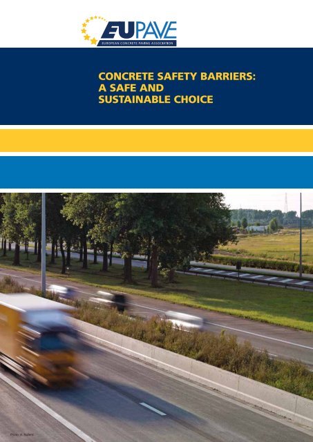
concrete safety barriers: a safe and sustainable choice - EUPAVE
concrete safety barriers: a safe and sustainable choice - EUPAVE
concrete safety barriers: a safe and sustainable choice - EUPAVE

You also want an ePaper? Increase the reach of your titles
YUMPU automatically turns print PDFs into web optimized ePapers that Google loves.
Photo: A. Nullens<br />
CONCRETE SAFETY BARRIERS:<br />
A SAFE AND<br />
SUSTAINABLE CHOICE
CONTENTS<br />
1. Introduction 3<br />
2. Benefits of <strong>concrete</strong> <strong><strong>safe</strong>ty</strong> <strong>barriers</strong> 4<br />
3. History of <strong><strong>safe</strong>ty</strong> <strong>barriers</strong> in Europe 5<br />
4. The European st<strong>and</strong>ards: EN 1317 8<br />
5. Performance <strong>and</strong> test methods for vehicle restraint systems 9<br />
6. Terminals, transitions <strong>and</strong> removable barrier sections 17<br />
7. CE marking of <strong>concrete</strong> <strong><strong>safe</strong>ty</strong> <strong>barriers</strong> 18<br />
8. Protection of motorcyclists 19<br />
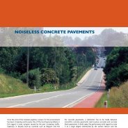
9. Road restraint systems <strong>and</strong> noise <strong>barriers</strong> 21<br />
10. Sustainability of <strong>concrete</strong> <strong><strong>safe</strong>ty</strong> <strong>barriers</strong> 22<br />
11. Design <strong>and</strong> construction 27<br />
12. Conclusions 30<br />
13. References 31<br />
Photo: M. Van Kerckhoven
INTRODUCTION<br />
Involvement in a road traffic crash is the leading cause of death <strong>and</strong> hospital admission for<br />
citizens of the European Union under the age of 45 years. With 39 000 road traffic deaths in<br />
2008 <strong>and</strong> socio-economic costs of € 180 billion, road <strong><strong>safe</strong>ty</strong> continues to be a priority area<br />
for action in the EU.<br />
Although the actions taken so far have been effective in several Member States, the numbers<br />
of road fatalities remain unacceptably high. That is why the European Commission (EC)<br />
has adopted challenging plans to reduce the number of road deaths on Europe’s roads by<br />
half in the next ten years.<br />
One of the seven strategic objectives, amongst others such as intelligent vehicles <strong>and</strong> better<br />
enforcement, is <strong>safe</strong>r road infrastructure. The use of passive <strong><strong>safe</strong>ty</strong> systems <strong>and</strong>, more<br />
specifically, road restraint systems undoubtedly contributes to higher <strong><strong>safe</strong>ty</strong>. There will also<br />
be more focus on vulnerable road users, motorcyclists in particular. [Ref. 8]<br />
Photo: Britpave<br />
3 CONCRETE SAFETY BARRIERS: A SAFE AND SUSTAINABLE CHOICE
2. BENEFITS OF CONCRETE SAFETY BARRIERS<br />
Another concern of the EC is the use of <strong>sustainable</strong><br />
solutions, fitting in the concept of<br />
Green Public Procurement. Concrete <strong><strong>safe</strong>ty</strong><br />
<strong>barriers</strong> give answers to both the issues of<br />
road <strong><strong>safe</strong>ty</strong> <strong>and</strong> sustainability. The figure<br />
> ENvIRONmENT > SOCIETY<br />
• 80% less embodied CO 2 than<br />
competing systems<br />
• Minimum material usage <strong>and</strong><br />
waste<br />
• Non polluting in service<br />
• 100% recyclable<br />
• Virtually maintenance-free over<br />
their 50-year design life<br />
• Reduce traffic congestion <strong>and</strong><br />
associated emissions<br />
ENVIRONMENT<br />
‘planet’<br />
4 CONCRETE SAFETY BARRIERS: A SAFE AND SUSTAINABLE CHOICE<br />
bearable<br />
‘SUSTAINABLE’<br />
viable equitable<br />
ECONOMY<br />
‘prosperity’<br />
> ECONOmIC FACTORS<br />
• Very long design life<br />
• Minimum space required<br />
• Almost maintenance-free<br />
• Remain functional even after<br />
severe collisions<br />
• High daily production of 400<br />
to 800 m possible<br />
• Temporary systems available<br />
for road works<br />
below lists the benefits of <strong>concrete</strong> <strong><strong>safe</strong>ty</strong><br />
<strong>barriers</strong> in the three domains of <strong>sustainable</strong><br />
construction: environment, economy<br />
<strong>and</strong> society. These statements will further<br />
be discussed in this publication.<br />
• Increasing <strong><strong>safe</strong>ty</strong> for road user<br />
<strong>and</strong> worker<br />
• No break-through of collision<br />
vehicle<br />
• Low maintenance increases<br />
road availability <strong>and</strong> reduces<br />
traffic congestion<br />
• Safe solution for motorcyclists<br />
SOCIETY<br />
‘people’
3. HISTORY OF CONCRETE SAFETY BARRIERS IN EUROpE<br />
Since the 1970s, the central reserves of highways<br />
<strong>and</strong> motorways in Europe have been<br />
protected with (steel) guardrail structures.<br />
The necessary maintenance on the road due<br />
to damages from accidents led to congestion,<br />
especially at narrow road sections.<br />
This raised the question of how to develop<br />
other types of roadside <strong><strong>safe</strong>ty</strong> structures.<br />
NEw JERSEY pROFILE<br />
The need for durable construction with<br />
minimal maintenance <strong>and</strong> without unac-<br />
One-sided version that was used in wider central reserves<br />
<strong>and</strong> roadsides<br />
5 CONCRETE SAFETY BARRIERS: A SAFE AND SUSTAINABLE CHOICE<br />
ceptable reduction in <strong><strong>safe</strong>ty</strong> soon arose.<br />
The <strong>concrete</strong> <strong><strong>safe</strong>ty</strong> barrier with what is<br />
known as a New Jersey profile fitted these<br />
requirements. This type of barrier was<br />
originally designed in America by General<br />
Motors in 1955 <strong>and</strong> first used in New Jersey.<br />
The first applications in Europe were<br />
found in Belgium <strong>and</strong> France from the<br />
1970s onwards. [Ref. 4]<br />
The New Jersey profile in Europe was more<br />
or less st<strong>and</strong>ardised in two versions:<br />
Double-sided version, for (very narrow) central reserves<br />
Figure 1 Versions of the old<br />
New Jersey barrier<br />
New Jersey barrier in<br />
the central reserve of a<br />
motorway<br />
Photo: W. Kramer
One of the first applications<br />
of the <strong>concrete</strong> step barrier<br />
on motorway E429 in<br />
Belgium (1999)<br />
Photo: P. Van Audenhove<br />
CONCRETE STEp BARRIER (CSB)<br />
International experience had shown that<br />
collisions of a small vehicle at high speed<br />
against the New Jersey profile often resulted<br />
in accidents where the vehicle turned<br />
over.<br />
This caused Rijkswaterstaat, the Dutch<br />
Road Administration, to explore other barrier<br />
profiles. In the 1990s they developed<br />
in the Netherl<strong>and</strong>s the “embedded step”<br />
profile, based upon the English “singleslope”<br />
barrier. The advantages of this step<br />
profile compared to the New Jersey profile<br />
is the greatly reduced chance of roll-over<br />
accidents <strong>and</strong> the reduced damage to the<br />
vehicle thanks to the “step”. [Ref. 4]<br />
6 CONCRETE SAFETY BARRIERS: A SAFE AND SUSTAINABLE CHOICE<br />
The <strong>concrete</strong> step barrier is today the st<strong>and</strong>ardised<br />
solution for cast in situ <strong>barriers</strong> in<br />
Europe.<br />
0,90<br />
0,05<br />
0,60<br />
0,25<br />
9,0 gon<br />
0,085<br />
9,0 gon<br />
0,05<br />
0,542<br />
Figure 2 St<strong>and</strong>ard geometry of the <strong>concrete</strong> step barrier
IN SITU CAST AND pRECAST<br />
CONCRETE SAFETY BARRIER<br />
A <strong>concrete</strong> barrier can either be cast in situ<br />
or be precast in a production unit.<br />
The in situ installation is done by means<br />
of a slipform paver using ready mixed<br />
<strong>concrete</strong>. This kind of installation allows<br />
very high daily production rates <strong>and</strong> consequently<br />
competitive prices. The barrier<br />
can be tied to the substructure (a cement<br />
treated or asphalt base layer) or can be surface<br />
mounted without any anchoring.<br />
Prefabricated elements are manufactured<br />
in an indoor environment <strong>and</strong> assembled<br />
on the worksite, making their installation<br />
less dependent on climatic conditions.<br />
Since they can easily be displaced, they are<br />
very often used for protection of the work<br />
site during road construction.<br />
Precast <strong>barriers</strong> in a permanent <strong>and</strong> a temporary installation<br />
7 CONCRETE SAFETY BARRIERS: A SAFE AND SUSTAINABLE CHOICE<br />
Surface mounted CSB<br />
installation<br />
Photo: BAM Wegen<br />
Photo: L. Rens<br />
Photo: Omnibeton – Deltabloc
EN 1317-1:1998<br />
EN 1317-1:2010 (revision)<br />
EN 1317-2:1998 + A1:2006<br />
EN 1317-2:2010 (revision)<br />
EN 1317-3:2000<br />
EN 1317-3:2010 (revision)<br />
4. THE EUROpEAN STANDARDS: EN 1317<br />
In the beginning of the 1990s, CEN, the European Committee for St<strong>and</strong>ardisation, set up a<br />
Technical Committee on road equipment (CEN/TC 226) <strong>and</strong> a working group (WG 1), dedicated<br />
to the drafting of st<strong>and</strong>ardised rules for different types of road restraint systems. The<br />
initial <strong>and</strong> revised versions, including amendments, of the European st<strong>and</strong>ards of the EN<br />
1317 series are the following (status August 2012):<br />
Terminology <strong>and</strong> general criteria for test methods<br />
Performance classes, impact test acceptance criteria <strong>and</strong> test methods for <strong><strong>safe</strong>ty</strong> <strong>barriers</strong> including vehicle parapets<br />
Performance classes, impact test acceptance criteria <strong>and</strong> test methods for crash cushions<br />
ENV 1317-4:2001 Performance classes, impact test acceptance criteria <strong>and</strong> test methods for terminals <strong>and</strong> transitions of <strong><strong>safe</strong>ty</strong> <strong>barriers</strong><br />
EN 1317-5:2007 + A2:2012 Product requirements <strong>and</strong> evaluation of conformity for vehicle restraint systems<br />
CEN/TR 1317-6:2012 Pedestrian restraint systems – Pedestrian parapets<br />
CEN/TS 1317-8:2012 Motorcycle road restraint systems which reduce the impact severity of motorcyclist collisions with <strong><strong>safe</strong>ty</strong> <strong>barriers</strong><br />
CEN/TR 16303-1 to 4:2012 Road restraint systems – Guidelines for computational mechanics of crash testing against vehicle restraint system<br />
The following normative documents are in phase of preparation (status August 2012):<br />
prEN 1317-4 Performance classes, impact test acceptance criteria <strong>and</strong> test methods for transitions <strong>and</strong> removable barrier sections<br />
prEN 1317-5 Product requirements, test / assessment methods <strong>and</strong> acceptance criteria for vehicle restraint systems<br />
Notes:<br />
prEN 1317-7 Performance classes, impact test acceptance criteria <strong>and</strong> test methods for terminals of <strong><strong>safe</strong>ty</strong> <strong>barriers</strong><br />
• crash cushions <strong>and</strong> pedestrian<br />
restraint systems will not be dealt with<br />
in this publication;<br />
• EN = European st<strong>and</strong>ard, approved<br />
• A = Amendment<br />
• ENV = Pre-st<strong>and</strong>ard<br />
• TS = Technical specification<br />
• TR = Technical report<br />
pr = project, in state of preparation,<br />
not yet approved<br />
8 CONCRETE SAFETY BARRIERS: A SAFE AND SUSTAINABLE CHOICE
5. pERFORmANCE AND TEST mETHODS FOR vEHICLE<br />
RESTRAINT SYSTEmS<br />
pERFORmANCE CLASSES –<br />
CONTAINmENT LEvELS<br />
The first version of the European st<strong>and</strong>ard<br />
EN 1317-2 was published in 1998. A revised<br />
version was published in 2010. The original<br />
version defined 10 performance classes.<br />
The higher the performance level, the<br />
stronger the construction needs to be in order<br />
to withst<strong>and</strong> higher impact dem<strong>and</strong>s.<br />
Each performance class refers to a number<br />
of crash tests. A road restraint system, allocated<br />
to a specific class, must be able to<br />
retain the specified vehicles at determined<br />
speeds <strong>and</strong> impact angles. Table 1 gives<br />
an overview of the different st<strong>and</strong>ardised<br />
crash tests.<br />
The following containment levels are<br />
defined (EN 1317-2:1998):<br />
• low angle containment:<br />
containment levels T1,T2 <strong>and</strong> T3;<br />
• normal containment:<br />
containment levels N1 <strong>and</strong> N2;<br />
• high containment:<br />
containment levels H1,H2 <strong>and</strong> H3;<br />
• very high containment:<br />
containment levels H4a <strong>and</strong> H4b.<br />
9 CONCRETE SAFETY BARRIERS: A SAFE AND SUSTAINABLE CHOICE<br />
The low angle containment levels are<br />
intended to be used only for temporary<br />
<strong><strong>safe</strong>ty</strong> <strong>barriers</strong>. However, temporary <strong><strong>safe</strong>ty</strong><br />
<strong>barriers</strong> can also be tested for higher levels<br />
of containment.<br />
A successfully tested barrier at a given<br />
containment level should be considered as<br />
having met the containment requirements<br />
of any lower level, except that N1 <strong>and</strong> N2<br />
do not include T3. This is because level T3<br />
includes a test with a rigid truck (TB41)<br />
while for levels N1 <strong>and</strong> N2 only crash tests<br />
with cars are provided.<br />
The very high containment levels H4a <strong>and</strong><br />
H4b should not be regarded as equivalent<br />
<strong>and</strong> no hierarchy is given between them.<br />
The difference in tests TB71 with a rigid<br />
truck <strong>and</strong> TB81 with an articulated truck<br />
originates from the use of significantly different<br />
types of heavy vehicles in different<br />
countries.<br />
TABLE 1 STANDARDISED CRASH TESTS<br />
Test Type of vehicle Mass<br />
(kg)<br />
Speed<br />
(km/h)<br />
TB11 car 900 100 20<br />
TB21 car 1300 80 8<br />
TB22 car 1300 80 15<br />
TB31 car 1500 80 20<br />
TB32 car 1500 110 20<br />
TB41 rigid truck 10000 70 8<br />
TB42 rigid truck 10000 70 15<br />
TB51 bus 13000 70 20<br />
TB61 rigid truck 16000 80 20<br />
TB71 rigid truck 30000 65 20<br />
TB81 articulated truck 38000 65 20<br />
Impact angle<br />
(o)
Table 2 gives an overview of the different<br />
containment levels.<br />
Since the revision of the st<strong>and</strong>ards EN 1317,<br />
parts 1, 2 <strong>and</strong> 3, in 2010, new containment<br />
levels “L” have been added to the classes<br />
of high <strong>and</strong> very high containment. The<br />
performance of the “L” classes is enhanced<br />
in respect to the corresponding H classes by<br />
the addition of test TB32 with a 1500-kg car.<br />
ASI (ACCELERATION SEvERITY<br />
INDEx)<br />
The index ASI is intended to give a measure<br />
of the severity of the motion for a person<br />
within a vehicle during an impact with a<br />
road restraint system. It is measured <strong>and</strong><br />
calculated as the resultant of the decelerations<br />
in different directions of a fixed point<br />
of the vehicle, close to the centre of mass.<br />
The higher the ASI index, the more severe<br />
the collision, in general.<br />
TABLE 2 CONTAINmENT LEvELS IN EN 1317-2:2010 (AFTER REvISION)<br />
10 CONCRETE SAFETY BARRIERS: A SAFE AND SUSTAINABLE CHOICE<br />
Example of a precast barrier with very high containment<br />
level (H4b) on a viaduct<br />
Photo: Deltabloc
THIv (THEORETICAL HEAD ImpACT<br />
vELOCITY)<br />
THIV was developed for assessing occupant<br />
impact severity for vehicles involved in<br />
road collisions with road vehicle restraint<br />
systems. The occupant is considered to be<br />
a freely moving object (head) that, as the<br />
vehicle changes its speed during contact<br />
with the vehicle restraint system, continues<br />
moving until it strikes a surface within the<br />
interior of the vehicle. The magnitude of<br />
the velocity of the theoretical head impact<br />
is considered to be a measure of the severity<br />
of the impact of the vehicle to the vehicle<br />
restraint system.<br />
ImpACT SEvERITY LEvELS<br />
The evaluation of the impact severity indices<br />
is carried out for cars (for the higher<br />
<strong>and</strong> very high containment levels, the<br />
considered test is TB11 <strong>and</strong> in case of the<br />
L classes, additionally test TB32). The severity<br />
level is determined by the highest value<br />
from the tests.<br />
Table 3 gives the subdivision in three impact<br />
severity classes A, B <strong>and</strong> C. For each of<br />
these classes, a maximum for the ASI value<br />
is specified together with a maximum for<br />
the THIV value, which is the same for the<br />
three classes (33 km/h). Impact severity<br />
level A affords a greater level of <strong><strong>safe</strong>ty</strong> for<br />
the occupant of a car involved in a collision<br />
than level B, <strong>and</strong> level B a greater level<br />
than C.<br />
11 CONCRETE SAFETY BARRIERS: A SAFE AND SUSTAINABLE CHOICE<br />
The level C was introduced through an<br />
amendment of the first version of EN<br />
1317-2. This amendment was controversial<br />
at the time since certain parties felt that an<br />
ASI value higher than 1,4 would be un<strong>safe</strong>.<br />
However, there had never been any conclusive<br />
tests on the relationship between ASI<br />
or THIV <strong>and</strong> the risk for injuries to vehicle<br />
occupants. This relationship was studied in<br />
2008 by engineering bureau Ove Arup &<br />
Partners Ltd. [Ref. 10]<br />
TABLE 3 ImpACT SEvERITY CLASSES<br />
IN EN 1317-2:2010 (AFTER REvISION)<br />
Impact severity class ASI THIV<br />
A ≤ 1,0 <strong>and</strong> ≤ 33 km/h<br />
B ≤ 1,4 <strong>and</strong> ≤ 33 km/h<br />
C ≤ 1,9 <strong>and</strong> ≤ 33 km/h
HIC vERSUS ASI<br />
The study consisted of three physical crash tests <strong>and</strong> 50 computer simulations. Injuries<br />
were measured <strong>and</strong> compared to limits obtained from tests with volunteers <strong>and</strong> tests<br />
with cadavers. The results were plotted against ASI <strong>and</strong> THIV, being the two significant<br />
quantities for impact severity assessment in EN 1317. Results showed that, although ASI<br />
did show a correlation with injury risk, the level chosen for the boundary between class<br />
B <strong>and</strong> C <strong>barriers</strong> in EN 1317 does not provide significant discrimination between higher<br />
<strong>and</strong> lower risk of injury.<br />
The figure below shows HIC, which st<strong>and</strong>s for Head Injury Criterion, plotted against<br />
accident severity, measured by ASI. The acceptable level for HIC is set at 325 which<br />
is half of the allowed value for head protection in the EuroNCAP (European New<br />
Car Assessment Programme) side-impact protocol. This very conservative approach<br />
corresponds to a risk of less than 10% of a moderate injury. From the results we<br />
see that for an ASI value of up to 1,6, the injuries are very low. Even with the conservative<br />
level of acceptable injury, ASI values up to 1,8 fall within the <strong>safe</strong> zone.<br />
Similar conclusions were drawn from testing on neck injuries: for crashes with ASI up<br />
to 1,7 injuries are unlikely. While boundaries between ASI classes seem to be arbitrarily<br />
chosen, the existing requirement in EN 1317 for THIV to be below 33 km/hr represents a<br />
reasonable threshold below which significant injury is unlikely to take place.<br />
HIC<br />
2400<br />
2200<br />
1600<br />
1200<br />
800<br />
650<br />
400<br />
325<br />
0<br />
Test Result<br />
Model Result<br />
EN 1317 classe B EN 1317 classe C<br />
EuroNCAP<br />
Acceptable<br />
1,0 1,2 1,4 1,6 1,8 2,0 2,2 2,4<br />
Figure 3 Relationship between HIC (head injury criterion) <strong>and</strong> ASI (acceleration severity index) [Ref. 10]<br />
12 CONCRETE SAFETY BARRIERS: A SAFE AND SUSTAINABLE CHOICE<br />
ASI
DEFORmATION OF THE<br />
RESTRAINT SYSTEm<br />
The deformation of <strong><strong>safe</strong>ty</strong> <strong>barriers</strong> during<br />
impact tests is characterised by the<br />
dynamic deflection, working width <strong>and</strong><br />
vehicle intrusion.<br />
The dynamic deflection (D m ) shall be the<br />
maximum lateral dynamic displacement of<br />
any point of the traffic face of the restraint<br />
system (see figure 4).<br />
The working width (W m ) is the maximum<br />
lateral distance between any part of the<br />
barrier on the undeformed traffic side <strong>and</strong><br />
the maximum dynamic position of any part<br />
of the barrier. If the vehicle body deforms<br />
around the vehicle restraint system so that<br />
the latter cannot be used for the purpose<br />
of measuring the working width, the maximum<br />
lateral position of any part of the vehicle<br />
shall be taken as an alternative (see<br />
figure 4).<br />
The vehicle intrusion (VI m ) of a Heavy Goods<br />
Vehicle (HGV) is its maximum dynamic lateral<br />
position from the undeformed traffic<br />
side of the barrier (see figure 4). It shall be<br />
evaluated from high speed photographic<br />
or video recordings.<br />
The dynamic deflection, the working width<br />
<strong>and</strong> the vehicle intrusion allow determination<br />
of the conditions for installation<br />
of each <strong><strong>safe</strong>ty</strong> barrier <strong>and</strong> also to define<br />
the distances to be provided in front of<br />
obstacles to permit the system to perform<br />
satisfactorily.<br />
EN 1317-2:2010 provides formulas to turn<br />
the measured figures D m , W m <strong>and</strong> VI m into<br />
normalised values D N , W N <strong>and</strong> VI N . For W N<br />
<strong>and</strong> VI N , classes of different levels are defined<br />
in EN 1317-2:2010 (see tables 4 <strong>and</strong> 5).<br />
13 CONCRETE SAFETY BARRIERS: A SAFE AND SUSTAINABLE CHOICE<br />
TABLE 4: CLASSES OF NORmALISED wORkINg<br />
wIDTH LEvELS (EN 1317-2:2010)<br />
Classes Levels of normalised working width<br />
W1 W ≤ 0,6 m<br />
N<br />
W2 W ≤ 0,8 m<br />
N<br />
W3 W ≤ 1,0 m<br />
N<br />
W4 W ≤ 1,3 m<br />
N<br />
W5 W ≤ 1,7 m<br />
N<br />
W6 W ≤ 2,1 m<br />
N<br />
W7 W ≤ 2,5 m<br />
N<br />
W8 W ≤ 3,5 m<br />
N<br />
In specific cases, e.g. when there is limited<br />
space between the vehicle restraint system<br />
<strong>and</strong> an obstacle, a class of working width<br />
less than W1 may be specified.<br />
TABLE 5: CLASSES OF NORmALISED vEHICLE<br />
INTRUSION (EN 1317-2:2010)<br />
Classes Levels of normalised vehicle intrusion<br />
VI1 VI ≤ 0,6 m<br />
N<br />
VI2 VI ≤ 0,8 m<br />
N<br />
VI3 VI ≤ 1,0 m<br />
N<br />
VI4 VI ≤ 1,3 m<br />
N<br />
VI5 VI ≤ 1,7 m<br />
N<br />
VI6 VI ≤ 2,1 m<br />
N<br />
VI7 VI ≤ 2,5 m<br />
N<br />
VI8 VI ≤ 3,5 m<br />
N<br />
In specific cases, a class of vehicle intrusion<br />
less than VI1 may be specified.
D m<br />
W m<br />
D m<br />
W m<br />
D m<br />
W m<br />
Dm Wm Vim 14 CONCRETE SAFETY BARRIERS: A SAFE AND SUSTAINABLE CHOICE<br />
Dynamic deflection, working width <strong>and</strong> vehicle intrusion are<br />
important parameters in defining the distance that should<br />
be allowed between the barrier <strong>and</strong> an obstacle such as<br />
lighting posts.<br />
Photo: www.gva.be<br />
Figure 4 Dynamic Deflection (D ), Working Width (W ) <strong>and</strong><br />
m m<br />
Vehicle Intrusion (VI ) - measured values<br />
m<br />
D m<br />
W m<br />
D m<br />
W m<br />
Dm Vim Wm
ImpACT TEST ACCEpTANCE<br />
CRITERIA<br />
The test parameters on which acceptance<br />
criteria shall be assessed are listed in table 6<br />
as a function of the containment level.<br />
TABLE 6: TEST CRITERIA pER CONTAINmENT LEvEL<br />
Containment<br />
level<br />
T1<br />
T2<br />
T3<br />
N1<br />
N2<br />
H1<br />
H2<br />
H3<br />
H4a<br />
H4b<br />
L1<br />
L2<br />
L3<br />
L4a<br />
L4b<br />
Safety barrier<br />
including parapet <strong>and</strong><br />
vehicle behavior<br />
TB 21<br />
TB 22<br />
TB 41 + TB 21<br />
TB 31<br />
TB 32 + TB 11<br />
TB 42 + TB 11<br />
TB 51 + TB 11<br />
TB 61 + TB 11<br />
TB 71 + TB 11<br />
TB 81 + TB 11<br />
TB 42 + TB 32 + TB 11<br />
TB 51 + TB 32 + TB 11<br />
TB 61 + TB 32 + TB 11<br />
TB 71 + TB 32 + TB 11<br />
TB 81 + TB 32 + TB 11<br />
NOTE: VCDI is not an acceptance criterion.<br />
15 CONCRETE SAFETY BARRIERS: A SAFE AND SUSTAINABLE CHOICE<br />
Impact severity<br />
level ASI-THIV<br />
TB 21<br />
TB 22<br />
TB 21<br />
TB 31<br />
TB 32 + TB 11 a<br />
TB 11<br />
TB 11<br />
TB 11<br />
TB 11<br />
TB 11<br />
TB 32 + TB 11a<br />
TB 32 + TB 11a<br />
T B 32 + TB 11a<br />
TB 32 + TB 11a<br />
T B 32 + TB 11a<br />
PARAMETERS<br />
Vehicle<br />
deformation<br />
(VCDI)<br />
TB 21<br />
TB 22<br />
TB 21<br />
TB 31<br />
TB 32 + TB 11<br />
TB 11<br />
TB 11<br />
TB 11<br />
TB 11<br />
TB 11<br />
TB 32 + TB 11<br />
TB 32 + TB 11<br />
TB 32 + TB 11<br />
TB 32 + TB 11<br />
TB 32 + TB 11<br />
Safety barrier<br />
including parapet<br />
deformation<br />
TB 21<br />
TB 22<br />
TB 41 + TB 21<br />
TB 31<br />
TB 32 + TB 11<br />
TB 42 + TB 11<br />
TB 51 + TB 11<br />
TB 61 + TB 11<br />
TB 71 + TB 11<br />
TB 81 + TB 11<br />
TB 42 + TB 32 + TB 11<br />
TB 51 + TB 32 + TB 11<br />
TB 61 + TB 32 + TB 11<br />
TB 71 + TB 32 + TB 11<br />
TB 81 + TB 32 + TB 11<br />
a : The severity level is determined by the highest value from the tests, all results to be included in the test report.<br />
Containment level<br />
Safety barrier including parapet <strong>and</strong> vehicle behavior<br />
Impact severity level ASI-THIV<br />
Vehicle deformation (VCDI)<br />
Safety barrier including parapet deformation<br />
PARAMETERS<br />
NOTE: VCDI is not an acceptance criterion.<br />
a: The severity level is determined by the highest value from the tests, all results to be included in the test report.
THE CONCRETE STEp BARRIER<br />
As already stated, the <strong>concrete</strong> step barrier is the st<strong>and</strong>ard solution for in situ cast <strong>concrete</strong><br />
vehicle restraint systems in Europe. The original tests, performed in 1995, resulted<br />
in the following performances:<br />
Containment level H2<br />
Working width W1 (*)<br />
Impact severity class B<br />
(*): The barrier will be deemed W1 under the requirements of EN1317-2:2010<br />
with a vehicle intrusion of VI2.<br />
In the meantime several variants of this solution have been developed, tested <strong>and</strong> adopted<br />
(free st<strong>and</strong>ing instead of restrained, different heights <strong>and</strong>/or widths etc.), mainly<br />
in Germany <strong>and</strong> the UK.<br />
Starting from the original step barrier design, Britpave, the British In-Situ Concrete Paving<br />
Association, has developed <strong>and</strong> tested a complete range of surface-mounted <strong>concrete</strong><br />
step barrier <strong><strong>safe</strong>ty</strong> restraint systems. This includes several new step barrier profiles,<br />
as well as transitions to other barrier systems <strong>and</strong> structures, sign <strong>and</strong> street lighting<br />
fixings, <strong>and</strong> gates for emergency crossing points <strong>and</strong> expansion joints. The Britpave surface-mounted<br />
CSB is a fully CE-marked barrier supplied through a network of Approved<br />
Licensed Installation companies.<br />
Surface-mounted CSB<br />
Photo: Britpave<br />
16 CONCRETE SAFETY BARRIERS: A SAFE AND SUSTAINABLE CHOICE
6. TERmINALS, TRANSITIONS AND REmOvABLE<br />
BARRIER SECTIONS<br />
Terminals are defined as the beginning<br />
<strong>and</strong>/or end treatment of a <strong><strong>safe</strong>ty</strong> barrier.<br />
They are required to have specified impact<br />
performances without introducing additional<br />
hazards for passenger cars.<br />
Problems may also arise in the connection<br />
between two different <strong><strong>safe</strong>ty</strong> <strong>barriers</strong> having<br />
consistent difference in design <strong>and</strong>/or<br />
in stiffness. Transitions are required to provide<br />
a smooth <strong>and</strong> <strong>safe</strong> change from one<br />
barrier to another.<br />
A removable barrier section is defined as a<br />
section of barrier connected to a barrier at<br />
both ends which allows for removal <strong>and</strong> reinstallation<br />
for temporary openings. These<br />
are mainly used for emergency reasons or<br />
maintenance access, <strong>and</strong> which, in closed<br />
position, offer appropriate containment<br />
performances.<br />
Photo: Deltabloc<br />
17 CONCRETE SAFETY BARRIERS: A SAFE AND SUSTAINABLE CHOICE<br />
ENV 1317-4 currently covers performance<br />
classes <strong>and</strong> test methods for terminals <strong>and</strong><br />
transitions. Several systems have been<br />
tested <strong>and</strong> approved to conform with ENV<br />
1317-4 for transitions between different<br />
<strong>concrete</strong> <strong><strong>safe</strong>ty</strong> <strong>barriers</strong> (precast-to-precast,<br />
in-situ-to-in-situ, precast-to-in-situ) or<br />
between <strong>concrete</strong> <strong>and</strong> steel <strong>barriers</strong>.<br />
Currently it is proposed to split the prest<strong>and</strong>ard<br />
ENV 1317-4 into two new st<strong>and</strong>ards:<br />
• EN 1317-4, dealing with transitions<br />
<strong>and</strong> removable barrier sections.<br />
• EN 1317-7, dealing with terminals. In<br />
general, a terminal is designed to provide<br />
an anchorage to the barrier. They<br />
can be energy absorbing or not.<br />
Photo: L. Rens<br />
Examples of transitions<br />
between different <strong>concrete</strong><br />
vehicle restraint systems<br />
Transition between a<br />
<strong>concrete</strong> step barrier <strong>and</strong> a<br />
steel system<br />
Photo: Linetech
7. CE mARkINg OF CONCRETE SAFETY BARRIERS<br />
CE marking is a declaration by the manufacturer<br />
that the product meets all the<br />
requirements of the relevant European<br />
legislation. CE marking is designed to remove<br />
trade <strong>barriers</strong> across the EU, giving<br />
companies easier access into the European<br />
market to sell their products without adaptation<br />
or rechecking. From 1st July 2013 onwards<br />
CE marking will be m<strong>and</strong>atory for all<br />
permanent <strong><strong>safe</strong>ty</strong> restraint barrier products<br />
throughout the EU.<br />
EN1317 is the product st<strong>and</strong>ard for vehicle<br />
restraint systems. Part 5 contains annex<br />
ZA, the “harmonised” part of the st<strong>and</strong>ard<br />
which is the basis for CE certification <strong>and</strong><br />
marking.<br />
Concrete <strong><strong>safe</strong>ty</strong> <strong>barriers</strong> must comply with<br />
the clauses of annex ZA of EN1317-5 so<br />
that the barrier system is installed as tested<br />
to the Type Testing (TT) <strong>and</strong> in accordance<br />
with the Manufacturer’s Installation Manual.<br />
All <strong>barriers</strong> are subject to the Factory<br />
Production Control (FPC) conditions for<br />
manufacturing processes.<br />
CSB constructed under BBS license audit conditions<br />
18 CONCRETE SAFETY BARRIERS: A SAFE AND SUSTAINABLE CHOICE<br />
Precast barrier systems, amongst which all<br />
types of steel guardrails, attain their CE<br />
mark on the barrier elements. This is because<br />
precast systems are manufactured in<br />
a factory. The installation of precast barrier<br />
is carried out at a separate location to<br />
the place of manufacture. Therefore it is<br />
essential that the elements are assembled<br />
according to the as tested product. By contrast<br />
in situ <strong>concrete</strong> <strong><strong>safe</strong>ty</strong> <strong>barriers</strong> are<br />
manufactured on site <strong>and</strong> therefore the installed<br />
system could carry the CE mark e.g.<br />
the Britpave surface mounted CSB.<br />
Photo: Britpave Barrier Systems (BBS)
8. pROTECTION OF mOTORCYCLISTS<br />
Example of a motorcyclist protection device, installed to an existing steel guardrail<br />
Photo: L. Rens<br />
Vehicle restraint systems are primarily designed<br />
to contain <strong>and</strong> redirect cars, buses<br />
<strong>and</strong> trucks. That means that they do not<br />
necessarily provide protection to other<br />
road users, in particular motorcyclists. On<br />
the contrary, in some cases road equipment<br />
can be an obstacle itself <strong>and</strong> pose impact<br />
hazards for two-wheelers. This is particularly<br />
true for wire-rope <strong>barriers</strong> <strong>and</strong> for<br />
conventional steel <strong>barriers</strong> fixed to steel<br />
posts. On the other h<strong>and</strong>, <strong>concrete</strong> <strong>barriers</strong><br />
with smooth continuous surfaces have<br />
seldom been reported as dangerous road<br />
equipment for powered two-wheelers.<br />
[Ref. 7]<br />
In different countries protection devices<br />
have been developed in order to protect<br />
motorcyclists, having fallen from their vehicle<br />
<strong>and</strong> whilst sliding along the ground,<br />
19 CONCRETE SAFETY BARRIERS: A SAFE AND SUSTAINABLE CHOICE<br />
from hitting the sharp cutting edges of the<br />
steel profiles. In many European countries,<br />
these devices are already being installed<br />
in dangerous spots, mainly curves with a<br />
small radius.<br />
At the same time, research has been done<br />
on methods for testing these devices (in<br />
Germany, Portugal <strong>and</strong> Spain). Based on<br />
the Spanish test method, a normative reference<br />
test has been discussed, <strong>and</strong> has<br />
become part 8 of the EN 1317 series, but<br />
under the form of a European Technical<br />
Specification CEN/TS 1317-8 “Motorcycle<br />
road restraint systems which reduce the impact<br />
severity of motorcyclist collisions with<br />
<strong><strong>safe</strong>ty</strong> <strong>barriers</strong>”. In the future, these Technical<br />
Specifications (TS) may be transformed<br />
into a real European St<strong>and</strong>ard EN.
30°<br />
Discontinuous system<br />
Continuous system<br />
Figure 5: one of the three impact configurations for the<br />
testing of motorcyclist protection systems<br />
Example of a cast in situ <strong>concrete</strong> step barrier<br />
Photo: L. Rens<br />
20 CONCRETE SAFETY BARRIERS: A SAFE AND SUSTAINABLE CHOICE<br />
In the selected test, only the “sliding”<br />
configuration is considered. (The German<br />
method also provides assessing the risk for<br />
cross-over accidents.) The impact conditions<br />
are the impact angle (30°), the speed<br />
(60 <strong>and</strong> 70 km/h) <strong>and</strong> the <strong>choice</strong> of impact<br />
point (3 different possibilities). In addition,<br />
the dummy that is used for the tests hits<br />
the protection device (or the barrier) with<br />
the head first, which can be considered as<br />
the most dangerous but also a rather unlikely<br />
situation. The test consists of measuring<br />
forces on the head <strong>and</strong> neck which<br />
are related to severity levels HIC 650 or HIC<br />
1000 (HIC = Head Injury Criterion).<br />
Due to the absence of support posts, <strong>concrete</strong><br />
<strong><strong>safe</strong>ty</strong> <strong>barriers</strong>, whether slipformed<br />
or precast, have a limited risk of impact<br />
injuries to motorcyclists.
9. ROAD RESTRAINT SYSTEmS AND NOISE BARRIERS<br />
Different st<strong>and</strong>ards exist for road restraint<br />
systems (series EN 1317) <strong>and</strong> for noise protection<br />
devices (series EN 1793 <strong>and</strong> 1794).<br />
Nevertheless, both can be combined in one<br />
system <strong>and</strong> be tested <strong>and</strong> approved for<br />
each of the functions.<br />
21 CONCRETE SAFETY BARRIERS: A SAFE AND SUSTAINABLE CHOICE<br />
Another solution consists of installing approved<br />
<strong>barriers</strong>, e.g. the step barrier, in<br />
front of many sorts of st<strong>and</strong>ardised noise<br />
protection devices.<br />
Example of a combined<br />
system of vehicle restraint<br />
system <strong>and</strong> noise barrier<br />
Photo: Deltabloc<br />
Example of a <strong>concrete</strong> step<br />
barrier installed in front of a<br />
noise barrier<br />
Photo: L. Rens
10. SUSTAINABILITY OF CONCRETE SAFETY BARRIERS<br />
[REF. 11]<br />
SUSTAINABLE DEvELOpmENT<br />
Sustainable development is defined by the<br />
World Commission on Environment <strong>and</strong><br />
Development as “development that meets<br />
the needs of the present without compromising<br />
the ability of future generations to<br />
meet their own needs”.<br />
The following principles are identified to<br />
assist in its delivery:<br />
• Living within environmental limits<br />
• Ensuring a strong, healthy <strong>and</strong> just<br />
society<br />
• Achieving a <strong>sustainable</strong> economy<br />
• Promoting good governance<br />
• Using sound science responsibly<br />
• Effectively, <strong>sustainable</strong> development<br />
involves successful integration across<br />
the ‘triple bottom line’ of environmental,<br />
economic <strong>and</strong> social issues.<br />
SUSTAINABILITY OF CONCRETE<br />
Concrete is one of the most versatile <strong>and</strong><br />
durable construction materials known to<br />
man, making it the most widely used construction<br />
material in the world. Concrete<br />
is also one of the more <strong>sustainable</strong> building<br />
materials when inherent performance<br />
properties are taken into account.<br />
ENvIRONmENT<br />
The cement <strong>and</strong> <strong>concrete</strong> sector is committed<br />
to an on-going, concerted <strong>and</strong> coordinated<br />
effort to reduce its impact on the<br />
environment. Key issues include:<br />
• Reductions in polluting <strong>and</strong> greenhouse<br />
gases during production;<br />
22 CONCRETE SAFETY BARRIERS: A SAFE AND SUSTAINABLE CHOICE<br />
• Efficient use of resources by way of<br />
re-used materials <strong>and</strong> by-products<br />
from other industrial processes, such<br />
as water, aggregates, fuel or alternative<br />
cementitious materials;<br />
• Recycling <strong>and</strong> reduced reliance on<br />
quarried material;<br />
• Environmental rehabilitation after<br />
industrial activity has ceased;<br />
• Development of low-energy, durable<br />
<strong>and</strong> maintenance-free buildings <strong>and</strong><br />
structures.<br />
SUSTAINABLE CONSUmpTION<br />
AND pRODUCTION<br />
PRoDuCTIoN of CoNCRETE BARRIER<br />
Concrete is specified according to EN 206<br />
or EN 13369 (precast). Thanks to the use of<br />
blended cement types or the addition of<br />
fly ash or ground granulated blast furnace<br />
slag, the embodied CO 2 of the barrier can<br />
be significantly reduced.<br />
Furthermore, the use of recycled aggregates<br />
such as recycled <strong>concrete</strong> aggregate<br />
(RCA) is permitted <strong>and</strong> technically feasible<br />
in <strong>concrete</strong> <strong>barriers</strong>.<br />
CoNSTRuCTIoN CoST<br />
Independent studies comparing the construction<br />
costs of various barrier systems<br />
confirm that the <strong>concrete</strong> barrier is an exceptionally<br />
competitive product.<br />
In addition, with the cost of l<strong>and</strong> being high<br />
<strong>and</strong> space limited, the maximum number<br />
of traffic lanes can be obtained by the low<br />
working widths provided by <strong>concrete</strong> <strong>barriers</strong>.<br />
Current steel barrier systems do not<br />
offer similar reductions to working width.
In 2007, Britpave commissioned engineering<br />
bureau Ove Arup & Partners Ltd.<br />
to undertake cost comparison studies [Ref.<br />
1-2-3] of various steel <strong>and</strong> <strong>concrete</strong> central<br />
reserve systems. Assuming typical road layouts,<br />
this work looked at both basic barrier<br />
construction costs <strong>and</strong> the influence<br />
of different central reserve layouts <strong>and</strong><br />
lighting column options. In terms of barrier<br />
costs alone, this work confirms that surface<br />
mounted <strong>concrete</strong> step barrier (H2, W2)<br />
compares favourably with steel systems,<br />
which provide inferior containment (N2)<br />
<strong>and</strong> working width (W3 or W4). For equivalent<br />
containment levels (H2), continuous<br />
deformable steel systems are considered by<br />
Arup to be prohibitively expensive.<br />
Investigating central reserve layouts <strong>and</strong><br />
lighting provision costs, Arup also reported<br />
that a <strong>concrete</strong> step barrier on a fully hardened<br />
central reserve is less expensive than<br />
an un-tensioned, corrugated steel beam<br />
solution with equivalent containment (H2),<br />
sited on a soft central reserve. Similarly, Britpave<br />
surface-mounted wide CSB profile with<br />
integral cable troughs <strong>and</strong> mounted light-<br />
23 CONCRETE SAFETY BARRIERS: A SAFE AND SUSTAINABLE CHOICE<br />
ing columns, constructed on fully hardened<br />
central reserve, provides a more economic<br />
solution than un-tensioned, corrugated<br />
beam <strong>barriers</strong> constructed on a central reserve<br />
with socketed lighting columns.<br />
MAINTENANCE AND SERVICE LIfE CoST<br />
With a service life of at least 50 years, compared<br />
with around 20 for steel solutions,<br />
<strong>concrete</strong> <strong>barriers</strong> offer significant comparative<br />
cost savings in terms of end-of-service<br />
barrier replacement alone.<br />
Virtually maintenance-free, even after severe<br />
impacts, further high potential savings<br />
to the tax-payer can be achieved. In<br />
addition, the inherently high containment<br />
level of <strong>concrete</strong> <strong><strong>safe</strong>ty</strong> <strong>barriers</strong> effectively<br />
eliminates crossover incidents, which improves<br />
<strong><strong>safe</strong>ty</strong> <strong>and</strong> avoids accident recovery<br />
costs as well as insurance claims. Congestion,<br />
resulting from accidents <strong>and</strong> routine<br />
road maintenance, costs society a lot of<br />
money. By increasing levels of motorist<br />
<strong><strong>safe</strong>ty</strong> <strong>and</strong> reducing maintenance requirements,<br />
<strong>concrete</strong> <strong>barriers</strong> help to reduce<br />
this cost considerably.<br />
Traces of tyres on a <strong>concrete</strong><br />
<strong><strong>safe</strong>ty</strong> barrier, showing its<br />
resistance to vehicle impacts<br />
Photo: L. Rens
Example of corrosion of a steel guardrail<br />
Photo: W. Kramer<br />
CLImATE CHANgE AND ENERgY<br />
EMBoDIED Co 2<br />
Comparisons undertaken using industryagreed<br />
values for construction materials<br />
indicate that <strong>concrete</strong> <strong>barriers</strong> out-perform<br />
competing steel solutions in terms of levels<br />
of embodied CO 2 . Table 2 of Britpave publication<br />
BP42 [Ref. 11] which compares material<br />
impacts only (including material production,<br />
manufacture <strong>and</strong> delivery to site),<br />
clearly shows that the average embodied<br />
quantity of CO 2 in a <strong>concrete</strong> step barrier<br />
(105 kg/m for the Britpave surface mounted<br />
<strong>concrete</strong> step barrier) is lower than competing<br />
N2 (156 kg/m) <strong>and</strong>, more applicably, H2<br />
(549 kg/m) steel alternatives over a 50-year<br />
period. Indeed, even average values for<br />
dual, surface mounted <strong>concrete</strong> step barrier<br />
(247 kg/m) <strong>and</strong> wide <strong>concrete</strong> step barrier<br />
(205 kg/m) solutions out-perform comparable<br />
H2 steel solutions.<br />
WHoLE-LIfE ENVIRoNMENTAL IMPACT<br />
While calculations of embodied CO 2 <strong>and</strong><br />
other greenhouse gases are important,<br />
whole life performance should always be<br />
24 CONCRETE SAFETY BARRIERS: A SAFE AND SUSTAINABLE CHOICE<br />
considered, given that it is the in-service<br />
impacts of buildings <strong>and</strong> civil engineering<br />
structures that typically dominate.<br />
With a maintenance-free service life of at<br />
least 50 years, <strong>concrete</strong> <strong>barriers</strong> require<br />
minimal levels of service-life maintenance<br />
activity <strong>and</strong> related traffic management. As<br />
a result, low levels of road-user disruption<br />
<strong>and</strong> congestion are predicted. As the effectiveness<br />
of catalytic converters for vehicles<br />
idling or travelling at low speed is dramatically<br />
reduced, the net result is an overall<br />
positive impact on service-life greenhouse<br />
gas emissions.<br />
Steel <strong>barriers</strong> have a design life of around<br />
20 years <strong>and</strong> require maintenance after vehicle<br />
impact, an activity often requiring traffic<br />
management <strong>and</strong> lane closures which<br />
contribute to congestion. As such, over the<br />
50-year lifecycle of <strong>concrete</strong> <strong>barriers</strong>, the<br />
comparable amount of work, vehicles <strong>and</strong><br />
energy required to install <strong>and</strong> maintain a<br />
steel barrier is likely to be much higher.<br />
NATURAL RESOURCES<br />
RECyCLINg<br />
Concrete <strong>barriers</strong> can be constructed using<br />
a wide range of secondary <strong>and</strong> recycled<br />
materials <strong>and</strong>, at the end of their design<br />
life, are fully recyclable.<br />
Concrete <strong>barriers</strong> are 100% recyclable – a<br />
practice now commonplace – providing<br />
good quality secondary aggregates, which<br />
are useable in a wide range of applications.<br />
While steel barrier systems are recyclable,<br />
the fact that they are typically hot-dip<br />
galvanised to prolong their service life<br />
introduces economic <strong>and</strong> environmental<br />
constraints. As galvanised steel is recycled<br />
with other steel scrap, the zinc used for galvanising<br />
volatilises early in the process <strong>and</strong><br />
must be collected for reprocessing. Zinc is a<br />
chemical waste subject to pollution control<br />
legislation <strong>and</strong> requires appropriate collection,<br />
treatment <strong>and</strong> disposal (or recycling)<br />
processes.
IN-SERVICE PoLLuTIoN<br />
Research since 1997 confirms that highway<br />
run-off from rural trunk roads <strong>and</strong> motorways<br />
contains pollutants such as metals,<br />
hydrocarbons, salts <strong>and</strong> nutrients as well<br />
as microbial waste. Sources of pollution<br />
are reported to include construction, operation<br />
<strong>and</strong> road maintenance operations.<br />
Steel <strong><strong>safe</strong>ty</strong> fences <strong>and</strong> street furniture are<br />
known to be a significant source of heavy<br />
metals in run-off, particularly in winter<br />
months.<br />
Concrete does not contain or leach contaminants<br />
<strong>and</strong> presents no risk to environmental<br />
pollution when used in highway<br />
applications. This is confirmed to be true<br />
even when crushed recycled <strong>concrete</strong> is<br />
used in unbound secondary applications.<br />
Highway maintenance programmes – which<br />
are more common for steel systems due to<br />
their deformability on impact <strong>and</strong> relatively<br />
short design life – are also known to<br />
significantly affect sediment accumulation<br />
in drainage systems. This impact is clearly<br />
minimised by <strong>concrete</strong> <strong>barriers</strong> as they require<br />
minimal maintenance throughout<br />
their 50-year design life <strong>and</strong> are typically<br />
situated on hardened medians.<br />
REBAR IMPACT<br />
While <strong>concrete</strong> barrier construction typically<br />
employs steel str<strong>and</strong> to optimise construction<br />
efficiency, the <strong>concrete</strong> barrier can<br />
incorporate rebar, which, depending on<br />
the manufacturer, is often manufactured<br />
from 100% recycled scrap using an electric<br />
arc furnace process. While steel manufacture<br />
is generally energy-intensive, it should<br />
be recognised that the energy needed to<br />
produce one tonne of reinforcing steel is as<br />
low as half of that required to produce the<br />
same mass of structural-grade steel.<br />
25 CONCRETE SAFETY BARRIERS: A SAFE AND SUSTAINABLE CHOICE<br />
LAND uPTAkE<br />
Concrete <strong>barriers</strong> require less l<strong>and</strong> than all<br />
competing barrier solutions. Concrete step<br />
<strong>barriers</strong> with containment levels N2 <strong>and</strong> H2<br />
have a working widths of W1 (0.6 metres)<br />
<strong>and</strong> W2 (0.8 metres) respectively, which is<br />
lower than for all other competing solutions<br />
with similar containment levels.<br />
ECoLogy<br />
Animals travel within <strong>and</strong> between feeding<br />
areas, territories <strong>and</strong> even countries. Such<br />
journeys are essential for the everyday<br />
survival of individual animals as well as for<br />
the maintenance of viable populations. In<br />
addition to the impact of mortality, there<br />
is the impact of reduced or prevented wildlife<br />
dispersal <strong>and</strong> the associated severance<br />
of wildlife territories <strong>and</strong> habitats.<br />
Whilst there are no known data available<br />
to compare the impacts of roads with or<br />
without <strong>concrete</strong> <strong>barriers</strong> on wildlife, one<br />
can easily imagine that that the installation<br />
of a solid central barrier could serve<br />
to increase wildlife mortality <strong>and</strong> habitat<br />
fragmentation. It is acknowledged that, by<br />
the very nature of its design, a steel barrier<br />
is less likely to block animal dispersal,<br />
compared with the solid face of a <strong>concrete</strong><br />
barrier. However, in order to minimise wildlife<br />
casualties, animal population fragmentation<br />
<strong>and</strong> risk to road users from vehicle<br />
collisions with wildlife, it is not the type of<br />
<strong><strong>safe</strong>ty</strong> barrier used that is important. Rather,<br />
it is the provision of effective <strong>and</strong> targeted<br />
mitigation measures that holds the<br />
key to reducing the environmental impact<br />
of road <strong><strong>safe</strong>ty</strong> <strong>barriers</strong>.<br />
The innovative design of ‘eco-passages’,<br />
such as culverts, bridges, viaducts <strong>and</strong><br />
overpasses across roads, in conjunction<br />
with effective <strong>and</strong> well maintained wildlife<br />
fencing for larger species, is considered<br />
to present the greatest opportunities for<br />
reducing the impacts of roads <strong>and</strong> road<br />
<strong><strong>safe</strong>ty</strong> <strong>barriers</strong> on wildlife.
CREATINg SUSTAINABLE<br />
COmmUNITIES<br />
CoNSTRuCTIoN WoRkER HEALTH AND<br />
SAfETy<br />
Highway authorities <strong>and</strong> contractors are<br />
committed to road worker health <strong>and</strong><br />
<strong><strong>safe</strong>ty</strong> by reducing exposure to live traffic<br />
<strong>and</strong> lessening risks when on the network,<br />
as well as improving driver awareness <strong>and</strong><br />
education. These include an urgent review<br />
of operations that require road workers<br />
to be exposed to live traffic, with a view<br />
to reducing risks, <strong>and</strong> a revision of maintenance<br />
priorities to reduce the number of<br />
visits <strong>and</strong> ad-hoc repairs <strong>and</strong> maintenance<br />
to cut the need for road workers to be on<br />
the network.<br />
Concrete <strong><strong>safe</strong>ty</strong> <strong>barriers</strong> mostly require no<br />
maintenance after impact by a vehicle, with<br />
the resultant avoidance of the repair <strong>and</strong><br />
associated traffic management activities.<br />
MoToRIST SAfETy<br />
Concrete <strong>barriers</strong> provide excellent levels<br />
of motorist <strong><strong>safe</strong>ty</strong>. Ove Arup & Partners<br />
Ltd., one of the world’s leading consultants,<br />
has undertaken EN 1317-compliant crash<br />
tests <strong>and</strong> related computer simulations to<br />
investigate the potential for injury from<br />
collisions with <strong>concrete</strong> step <strong>barriers</strong> <strong>and</strong><br />
alternative <strong><strong>safe</strong>ty</strong> <strong>barriers</strong>. EN 1317 uses ASI<br />
values for assessing the impact on vehicle<br />
occupants <strong>and</strong> the ASI values recorded for<br />
<strong>concrete</strong> <strong>barriers</strong> tend to be higher than<br />
those for deformable steel <strong>barriers</strong>. However,<br />
the study proves that there is no direct<br />
correlation between the measured ASI<br />
values <strong>and</strong> the level of injury. Details of the<br />
study are explained in the part “HIC versus<br />
ASI” on pages 11-12.<br />
26 CONCRETE SAFETY BARRIERS: A SAFE AND SUSTAINABLE CHOICE<br />
In reality, <strong>concrete</strong> <strong>barriers</strong> also help to<br />
eliminate injury <strong>and</strong> deaths associated with<br />
cross-over accidents, barrier intrusions <strong>and</strong><br />
deflections, <strong>and</strong> loss of vehicular control on<br />
soft verges, all of which are typical of steel<br />
barrier systems. Requiring almost no maintenance<br />
or repair after a collision, <strong>concrete</strong><br />
<strong>barriers</strong> will also help to avoid motorway<br />
accidents in coned areas, such as those required<br />
for maintenance activities.<br />
VISuAL IMPACT<br />
Visually, <strong>concrete</strong> <strong>barriers</strong> provide a smooth,<br />
continuous structure that is relatively consistent<br />
in terms of texture <strong>and</strong> colour. Although<br />
colour is likely to change with time,<br />
due to the natural degradation of waterbased<br />
curing compounds <strong>and</strong> weathering,<br />
it should remain consistent. From the motorist’s<br />
visual perspective, <strong>concrete</strong> <strong>barriers</strong><br />
present a low-level screen that helps to reduce<br />
glare at night from oncoming traffic.<br />
From a motorist-<strong><strong>safe</strong>ty</strong> point of view, the<br />
visual impact of <strong>concrete</strong> <strong>barriers</strong> has been<br />
reported to potentially reduce average<br />
traffic speeds.<br />
NoISE IMPACT<br />
In 2005, Britpave commissioned a study to<br />
investigate the impact on roadside noise<br />
arising from the presence of <strong>concrete</strong> <strong>barriers</strong><br />
in the central reserve. Arup Acoustics<br />
conducted a field study <strong>and</strong> theoretical<br />
analysis to establish any differences in<br />
roadside noise levels, comparing <strong>concrete</strong><br />
<strong>and</strong> steel central reserve <strong>barriers</strong>.<br />
The results from the empirical <strong>and</strong> theoretical<br />
studies show that there is a negligible<br />
difference in roadside noise levels<br />
comparing <strong>concrete</strong> <strong>and</strong> steel central reserve<br />
<strong>barriers</strong>.
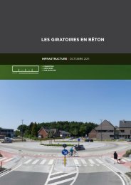
11. DESIgN AND CONSTRUCTION<br />
gENERAL<br />
Concrete <strong>barriers</strong> can be applied in different<br />
situations. If a central reserve has no<br />
obstacles, a double-sided profile is the obvious<br />
<strong>choice</strong>. When there are obstacles in<br />
the central reserve, such as lighting poles<br />
or columns of portals, a double single-sided<br />
profile can be chosen as an appropriate solution.<br />
It is also technically feasible to build<br />
widened <strong>concrete</strong> barrier profiles, in which<br />
lighting poles can be integrated.<br />
DRAINAgE<br />
When the slope of the pavement runs towards<br />
the barrier, removal of rainwater<br />
should be taken into account. Drainage<br />
near the barrier can be achieved with<br />
transverse openings at the foot of the barrier,<br />
whether or not combined with a drainage<br />
system.<br />
pRECAST CONCRETE BARRIER<br />
Precast <strong>concrete</strong> barrier elements are factory<br />
produced in reinforced <strong>concrete</strong>.<br />
At the end of the elements, producer-<br />
27 CONCRETE SAFETY BARRIERS: A SAFE AND SUSTAINABLE CHOICE<br />
patented connection systems are constructed,<br />
allowing the elements to form<br />
a rigid chain. For systems placed on main<br />
roads, this interconnection is required.<br />
The st<strong>and</strong>ard length is usually 6 m; the<br />
mass associated with this length can be<br />
h<strong>and</strong>led with an assembly crane. With elements<br />
of 6 m, curves with a radius greater<br />
than R = 250 m can be achieved. For smaller<br />
radii, shorter elements should be applied.<br />
The elements are already provided with<br />
openings at the bottom for drainage /<br />
throughput. The openings are also used for<br />
h<strong>and</strong>ling <strong>and</strong> placement of the elements.<br />
Note: Suppliers of precast <strong>concrete</strong> barrier<br />
elements usually have several types /<br />
profiles of barrier systems, suitable for different<br />
performance classes <strong>and</strong> temporary<br />
situations.<br />
ASSEMBLy<br />
The installation of precast <strong>concrete</strong> <strong>barriers</strong><br />
is usually executed by the supplier. The<br />
principal contractor must ensure the right<br />
place for installation <strong>and</strong> a flat surface,<br />
usually asphalt.<br />
Installation of precast<br />
<strong>concrete</strong> <strong>barriers</strong><br />
Photo: L. Rens
The <strong>barriers</strong> are installed directly from the<br />
truck. Additionally, for large quantities, a<br />
depot in the vicinity of the site is made,<br />
from where the <strong>barriers</strong> are transported to<br />
the site.<br />
IN SITU CONCRETE BARRIERS<br />
The in-situ cast barrier is built on a base<br />
surface of asphalt or lean <strong>concrete</strong>.<br />
Construction is done with a custom slipform<br />
paver with a mould. Production rates<br />
of 400 to 600 meters are achievable. Behind<br />
the machine, the extruded profile of<br />
fresh <strong>concrete</strong> should not deform. For this<br />
purpose it is advisable to apply a low-slump<br />
<strong>concrete</strong> with crushed aggregates, to obtain<br />
a stable mixture.<br />
The following specifications are recommended<br />
for the <strong>concrete</strong> mix in an exterior<br />
environment where de-icing salts are<br />
used (based on the st<strong>and</strong>ard for <strong>concrete</strong>,<br />
EN 206):<br />
Photo: Wirtgen Photo: Gomaco<br />
Photo: Power Curbers<br />
28 CONCRETE SAFETY BARRIERS: A SAFE AND SUSTAINABLE CHOICE<br />
• Compressive strength class: C28/35 or<br />
C30/37<br />
• exposure class: XF4 (use of an air<br />
entrainer)<br />
• maximum aggregate size: 22 mm<br />
• slump class: S1 (a maximum slump of<br />
30 mm is preferred)<br />
• minimum 340 kg of cement/m³<br />
• maximum water-cement ratio of 0.50<br />
• crushed gravel or limestone<br />
aggregates<br />
• use of a mix of coarse <strong>and</strong> fine s<strong>and</strong><br />
in order to obtain a smooth closed<br />
surface
In the length of the barrier two galvanised<br />
steel str<strong>and</strong>s are included. These str<strong>and</strong>s<br />
ensure that the barrier remains longitudinally<br />
aligned.<br />
In situ construction of <strong>concrete</strong> <strong><strong>safe</strong>ty</strong> <strong>barriers</strong> with the use<br />
of a slipform paver<br />
Photo: Wirtgen<br />
29 CONCRETE SAFETY BARRIERS: A SAFE AND SUSTAINABLE CHOICE<br />
To ensure controlled cracking the barrier<br />
is sawed every 4 to 6 metres to a depth<br />
of approximately 3 cm. This sawing happens,<br />
depending on weather conditions<br />
<strong>and</strong> temperature, between 6 <strong>and</strong> 24<br />
hours after the construction of the barrier.<br />
Photo: Power Curbers<br />
Photo: Gomaco
12. CONCLUSIONS<br />
Concrete <strong><strong>safe</strong>ty</strong> <strong>barriers</strong>, both cast in<br />
situ <strong>and</strong> precast, have been used as vehicle<br />
restraint systems for more than 40<br />
years. Their design <strong>and</strong> construction have<br />
been modified <strong>and</strong> improved in order<br />
to comply with the European st<strong>and</strong>ards<br />
EN 1317. Today, they offer a solution<br />
that meets the requirements of durability,<br />
<strong><strong>safe</strong>ty</strong>, economy <strong>and</strong> environment.<br />
Concrete is known for its durability <strong>and</strong> robustness.<br />
This is also the case for <strong>concrete</strong><br />
<strong><strong>safe</strong>ty</strong> <strong>barriers</strong> which have a service life of<br />
over 50 years, do not deform <strong>and</strong> mostly<br />
even stay intact after severe vehicle collisions,<br />
<strong>and</strong> are resistant to all types of climatic<br />
conditions.<br />
In terms of <strong><strong>safe</strong>ty</strong>, a <strong>concrete</strong> <strong><strong>safe</strong>ty</strong> barrier<br />
offers a high containment <strong>and</strong> thus reduces<br />
the risk of crossover accidents. It is designed<br />
to redirect errant vehicles without unacceptable<br />
risks for both vehicle occupants<br />
<strong>and</strong> other road users <strong>and</strong> third parties.<br />
Thanks to its smooth continuous surface<br />
<strong>and</strong> the absence of posts, the risk of impact<br />
injuries of motorcyclists is also reduced.<br />
The economic benefits are the relatively<br />
low initial construction cost, the rapid <strong>and</strong><br />
30 CONCRETE SAFETY BARRIERS: A SAFE AND SUSTAINABLE CHOICE<br />
easy installation <strong>and</strong> the fact that <strong>concrete</strong><br />
<strong>barriers</strong> hardly need maintenance over<br />
their service life.<br />
The environmental strong points are inherent<br />
to the use of <strong>concrete</strong>, which in<br />
itself is a <strong>sustainable</strong> material with limited<br />
embodied energy <strong>and</strong> carbon footprint<br />
considered over the entire lifecycle <strong>and</strong><br />
with the possibility of using recycled aggregates.<br />
Thanks to the minimum working<br />
width, <strong>concrete</strong> <strong>barriers</strong> require less space<br />
<strong>and</strong> only one <strong>concrete</strong> barrier is needed in<br />
the central reservation to serve both sides<br />
of the road. In addition, they cause no pollution<br />
<strong>and</strong> are fully recyclable at the end<br />
of life. As it is a maintenance-free system,<br />
road availability is increased <strong>and</strong> traffic<br />
congestion reduced.<br />
Finally, <strong>concrete</strong> <strong><strong>safe</strong>ty</strong> <strong>barriers</strong>, precast <strong>and</strong><br />
cast in situ, exist in a wide range of complete<br />
<strong>and</strong> tested solutions. The <strong>concrete</strong><br />
step barrier is the st<strong>and</strong>ard solution for insitu<br />
cast <strong>concrete</strong> vehicle restraint systems<br />
in Europe.<br />
Concrete <strong><strong>safe</strong>ty</strong> <strong>barriers</strong> are a <strong>safe</strong> <strong>and</strong> <strong>sustainable</strong><br />
<strong>choice</strong>!<br />
Photo: Omnibeton – Deltabloc
13. REFERENCES<br />
1. Barrier cost comparison – Study 1 of 3 (ref. BP37). ISBN: 978-0-9556962-2-0, Britpave, 2008.<br />
2. Barrier cost comparison – Study 2 of 3 (ref. BP38). ISBN: 978-0-9556962-3-7, Britpave, 2008.<br />
3. Barrier cost comparison – Study 3 of 3 (ref. BP39). ISBN: 978-0-9556962-4-4, Britpave, 2008.<br />
4. Beton – Goed op weg – De betonnen Step Barrier (Concrete – Well on track –<br />
the Concrete Step Barrier), Cement&BetonCentrum, 2010<br />
5. Britpave CSB – The guarantee of <strong><strong>safe</strong>ty</strong> <strong>and</strong> quality, Britpave Barrier Systems, 2012.<br />
6. Concrete <strong>barriers</strong> <strong>and</strong> roadside noise, DS/CSB/515, Britpave, November 2006.<br />
7. Hampton C. G. The risk of fatality in motorcycle crashes with roadside <strong>barriers</strong>,<br />
Paper number 07-0474, Virginia Tech, United States.<br />
8. http://ec.europa.eu<br />
9. Moderne betonschutzwände (Modern <strong>concrete</strong> <strong><strong>safe</strong>ty</strong> <strong>barriers</strong>),<br />
Gütegemeinschaft Betonschutzw<strong>and</strong> & Gleitformbau e.V. 2010<br />
10. Sturt, R. & Fell, C. The relationship of injury risk to accident severity in impacts<br />
with roadside <strong>barriers</strong>, International Journal of Crashworthiness, Vol. 14, N°. 2,<br />
April 2009, 165-172.<br />
11. Sustainability Benefits of Concrete Step Barrier – delivering a <strong>safe</strong>, reliable future,<br />
BP/42, Britpave, 2008.<br />
31 CONCRETE SAFETY BARRIERS: A SAFE AND SUSTAINABLE CHOICE
Published by:<br />
EuPAVE<br />
European Concrete<br />
Paving Association<br />
Vorstlaan 68 boulevard du Souverain<br />
1170 brussels<br />
T + 32 2 790 42 06<br />
f + 32 2 640 06 70<br />
info@eupave.eu<br />
www.eupave.eu<br />
Photo: Agentschap Wegen en Verkeer, Fl<strong>and</strong>ers, Belgium<br />
December 2012