HID TROUBLESHOOTING GUIDE - ExceLine
HID TROUBLESHOOTING GUIDE - ExceLine
HID TROUBLESHOOTING GUIDE - ExceLine

Create successful ePaper yourself
Turn your PDF publications into a flip-book with our unique Google optimized e-Paper software.
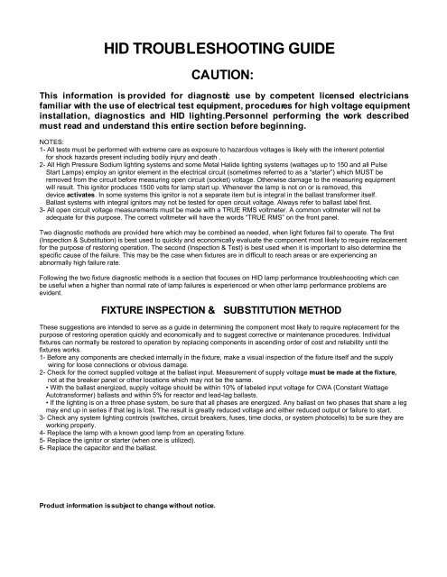
<strong>HID</strong> <strong>TROUBLESHOOTING</strong> <strong>GUIDE</strong><br />
CAUTION:<br />
This information is provided for diagnostic use by competent licensed electricians<br />
familiar with the use of electrical test equipment, procedures for high voltage equipment<br />
installation, diagnostics and <strong>HID</strong> lighting. Personnel performing the work described<br />
must read and understand this entire section before beginning.<br />
NOTES:<br />
1- All tests must be performed with extreme care as exposure to hazardous voltages is likely with the inherent potential<br />
for shock hazards present including bodily injury and death .<br />
2- All High Pressure Sodium lighting systems and some Metal Halide lighting systems (wattages up to 150 and all Pulse<br />
Start Lamps) employ an ignitor element in the electrical circuit (sometimes referred to as a “starter”) which MUST be<br />
removed from the circuit before measuring open circuit (socket) voltage. Otherwise damage to the measuring equipment<br />
will result. This ignitor produces 1500 volts for lamp start up. Whenever the lamp is not on or is removed, this<br />
device activates. In some systems this ignitor is not a separate item but is integral in the ballast transformer itself.<br />
Ballast systems with integral ignitors may not be tested for open circuit voltage. Always refer to ballast label first.<br />
3- All open circuit voltage measurements must be made with a TRUE RMS voltmeter. A common voltmeter will not be<br />
adequate for this purpose. The correct voltmeter will have the words “TRUE RMS” on the front panel.<br />
Two diagnostic methods are provided here which may be combined as needed, when light fixtures fail to operate. The first<br />
(Inspection & Substitution) is best used to quickly and economically evaluate the component most likely to require replacement<br />
for the purpose of restoring operation. The second (Inspection & Test) is best used when it is important to also determine the<br />
specific cause of the failure. This may be the case when fixtures are in difficult to reach areas or are experiencing an<br />
abnormally high failure rate.<br />
Following the two fixture diagnostic methods is a section that focuses on <strong>HID</strong> lamp performance troubleshoooting which can<br />
be useful when a higher than normal rate of lamp failures is experienced or when other lamp performance problems are<br />
evident.<br />
FIXTURE INSPECTION & SUBSTITUTION METHOD<br />
These suggestions are intended to serve as a guide in determining the component most likely to require replacement for the<br />
purpose of restoring operation quickly and economically and to suggest corrective or maintenance procedures. Individual<br />
fixtures can normally be restored to operation by replacing components in ascending order of cost and reliability until the<br />
fixtures works.<br />
1- Before any components are checked internally in the fixture, make a visual inspection of the fixture itself and the supply<br />
wiring for loose connections or obvious damage.<br />
2- Check for the correct supplied voltage at the ballast input. Measurement of supply voltage must be made at the fixture,<br />
not at the breaker panel or other locations which may not be the same.<br />
• With the ballast energized, supply voltage should be within 10% of labeled input voltage for CWA (Constant Wattage<br />
Autotransformer) ballasts and within 5% for reactor and lead-lag ballasts.<br />
• If the lighting is on a three phase system, be sure that all phases are energized. Any ballast on two phases that share a leg<br />
may end up in series if that leg is lost. The result is greatly reduced voltage and either reduced output or failure to start.<br />
3- Check any system lighting controls (switches, circuit breakers, fuses, time clocks, or system photocells) to be sure they are<br />
working properly.<br />
4- Replace the lamp with a known good lamp from an operating fixture.<br />
5- Replace the ignitor or starter (when one is utilized).<br />
6- Replace the capacitor and the ballast.<br />
Product information is subject to change without notice.
FIXTURE INSPECTION & TEST METHOD<br />
<strong>HID</strong> <strong>TROUBLESHOOTING</strong> <strong>GUIDE</strong><br />
In some situations a full diagnostic procedure is necessary in addition to the inspection and substitution method described<br />
previously. This method is useful when fixtures are difficult to reach or are experiencing abnormally high failure rates. This<br />
method is also better suited to determining not only what component has failed in the system but what caused it to fail.<br />
Inspect the outside first.<br />
Before any components are checked internally in the fixture, make a visual inspection of the fixture itself and the supply wiring<br />
for loose connections or obvious damage.<br />
Inspect the lamp.<br />
1. Look for cracks in the bulb wall or broken parts internally.<br />
2. Look for cracks or seal leakage where the envelope meets the base.<br />
(Separation of the base or discoloration on inside of the bulb wall).<br />
3. Significant blackening of the arc tube located in the middle of the lamp.<br />
4. Check to see if the ANSI designation is correct.<br />
The ANSI number for the lamp must match the ANSI number for the ballast in the system. The ANSI number would<br />
generally NOT match if a different wattage or light source were employed for either the lamp or the ballast.<br />
5. Check for correct orientation of lamp base:<br />
Base UP (BU)<br />
Base Down (BD)<br />
Universal (U)<br />
NOTE: Characters in parenthesis are typically used by the lamp manufacturer to indicate lamp orientation.<br />
Inspect electrical system components.<br />
1. Check leads for loose connections, damaged wires or loose wire nuts.<br />
2. Check multi-tap ballast to make sure the incoming line voltages is on the proper tap of the ballast.<br />
3. Check for swollen or ruptured capacitor case.<br />
4. Check to see if the capacitor rating and microfarad (uF) value, printed on the case, agree with the capacitor rating and<br />
microfarad value printed on the ballast label.<br />
5. Check to see if the socket is broken or if the lamp is unable to make electrical contact in it.<br />
6. Check ballast for breakage such as separation of metal frame which is made of many small plates. (This does not apply to<br />
electronic ballasts.)<br />
7. Check ballast label to ensure correct type for the light source and wattage of the lamp used. Verify that the ANSI number is<br />
the same for both ballast and lamp.<br />
8. Check to see that the ignitor is the correct type (where applicable) by comparing the part number on the ignitor case with the<br />
one printed on the ballast label.<br />
Electrical Tests<br />
1. Check for the correct supplied voltage at the ballast input. Measurement of supply voltage must be made at the fixture, not<br />
at the breaker panel or other locations which may not be the same.<br />
• With the ballast energized, supply voltage should be within 10% of labeled input voltage for CWA (Constant<br />
Wattage Autotransformer) ballasts and within 5% for reactor and lead-lag ballasts.<br />
2. If the lighting is on a three phase system, be sure that all phases are energized. Any ballast on two phases that share<br />
a leg may end up in series if that leg is lost. The result is greatly reduced voltage and either reduced output or failure to start.<br />
3. Check any system lighting controls (switches, circuit breakers, fuses, time clocks, or system photocells) to be sure<br />
they are working properly.<br />
4. Check the open circuit voltage of the fixture (voltage to the socket with the lamp removed).<br />
DANGER! Please read and understand the following notes before conducting electrical tests.<br />
NOTES:<br />
A. All tests must be performed with extreme care as exposure to hazardous voltages is likely with the inherent<br />
potential for electrical shock including bodily injury and death present.<br />
B. All High Pressure Sodium lighting systems and some Metal Halide lighting systems (wattages up to 150 and all Pulse<br />
Start Lamps) employ an ignitor element in the electrical circuit (sometimes referred to as a “starter”) which MUST be<br />
removed from the circuit before measuring open circuit (socket) voltage. Otherwise damage to the measuring equipment will<br />
result. The ignitor produces 1500 volts for lamp start up. Whenever the lamp is not on or is removed, this device activates. In<br />
some systems this ignitor is not a separate item but is integral in the ballast transformer itself. Ballast systems with integral<br />
ignitors may not be tested for open circuit voltage. Always refer to ballast label first.<br />
C. All open circuit voltage measurements must be made with a TRUE RMS voltmeter. A common voltmeter will not be<br />
adequate for this purpose. The correct voltmeter will have the words “TRUE RMS” on the front panel.
<strong>HID</strong> <strong>TROUBLESHOOTING</strong> <strong>GUIDE</strong><br />
TYPICAL OPEN CIRCUIT VOLT AGES (Lamps Removed) FOR <strong>HID</strong> SOU RCES<br />
NOTES:<br />
1- Open circuit voltages are provided for diagnostic use by a competent licensed electrician only.<br />
2- All High Pressure Sodium sources and some Metal Halide sources employ an ignitor which must be removed from the<br />
circuit before measuring open circuit voltage. Otherwise, damage to the measuring equipment will result. The ignitor<br />
produces 1500 volts for lamp start-up. Ballasts with integral ignitors should not be tested.<br />
3- All open circuit voltage measurements must be made with a TRUE RMS volt meter. A common voltmeter will not be<br />
adequate for this purpose.<br />
High Pressure Sodium OPEN CIRCUIT<br />
(60 Hz) VOLTS<br />
35 Watt 120<br />
50 Watt 120<br />
70 Watt 120<br />
70 Watt – CWA ballast 105<br />
100 Watt 120<br />
100 Watt – CWA & Reg. Lab ballasts 115<br />
150 Watt – 55 volt lamps 120<br />
150 Watt – CWA ballast w/ 55 volt lamp 110<br />
150 Watt – Reg. Lag ballast w/ 55 volt lamp 120<br />
150 Watt – 100 volt (S56) lamps 230<br />
150 Watt – CWA 100 volt lamps 180<br />
200 Watt 230<br />
200 Watt – CWA ballast 195<br />
200 Watt – Reg. Lag ballast 225<br />
250 Watt 230<br />
250 Watt – CWA ballast 187<br />
250 Watt – Reg. Lag ballast 215<br />
250 Watt – Low Loss Reg. Lag ballast 220<br />
400 Watt 230<br />
400 Watt – CWA ballast 191<br />
400 Watt – Reg. Lag ballast 215<br />
1000 Watt – CWA ballast 435<br />
NOTES:<br />
Normal and High Power Factor Ballast circuit given unless noted as follows:<br />
CWA = Constant Wattage Autotransformer Type Ballast Circuit.<br />
Reg. Lag = Regulated Lag Type Ballast Circuit.<br />
Other notes refer to specific lamp types.<br />
Metal Halide OPEN CIRCUIT<br />
(60 Hz) VOLTS<br />
50 Watt 230<br />
70 Watt 230<br />
100 Watt 277<br />
100 Watt – CWA ballast 240<br />
150 Watt 230<br />
150 Watt – CWA ballast 187<br />
150 Watt – M107 lamp (operated on 175 watt ballast) 300<br />
175 Watt – CWA ballast 300<br />
250 Watt 250<br />
250 Watt – CWA ballast 290/310<br />
400 Watt – CWA ballast 310<br />
1000 Watt – CWA ballast 425<br />
Product information is subject to change without notice.
<strong>HID</strong> <strong>TROUBLESHOOTING</strong> <strong>GUIDE</strong><br />
<strong>HID</strong> LAMP PERFORMANC E TROUBLES HOOTING<br />
Normal End of Lamp Life<br />
1. Normal end of life is important to understand for troubleshooting. It occurs when the lamp has aged to the point<br />
that the arc can no longer be sustained. End of life can be induced prematurely when lamps are operated at<br />
improper voltages, temperatures and positions.<br />
• Mercury and Metal Halide lamps tend to emit low light output at end of life and starting will become<br />
intermittent. There will also be significant blackening on the arc tube located at the center of the lamp.<br />
• High Pressure Sodium lamps retain their light output at the end of life, however, starting becomes intermittent<br />
at first and then impossible. There will be some blackening on the end of the arc tube located in the center of<br />
the lamp.<br />
• Verify average rated lamp life as published by the lamp manufacturer and compare it to the actual life of the<br />
lamps in the system. Remember that the average rated life is not the same as the minimum life expectancy.<br />
The average rated life means that for a population of lamps, the average lamp lasted this long. When a<br />
system of lamps installed at the same time reaches the average rated life, we can expect half of the<br />
population of lamps to have failed. It is always important to be aware of the operation of the system when<br />
evaluating lamp life. For example, is the system operated round the clock either intentionally or as the result<br />
of faulty controls?<br />
Lamps Will Not Start<br />
1. Check to see if lamp is loose in the socket.<br />
• Check for arcing (blackening) at the center contact button and retighten lamp until it is properly seated.<br />
Tightening too much may cause lamp breakage.<br />
2. Check to see if lamp has failed or is damaged.<br />
• Visually inspect for loose broken internal parts or broken bulb wall.<br />
• Visually inspect for separation of the lamp base. Check for looseness or for significant discoloration of the bulb<br />
wall near the base.<br />
• Test the lamp in an adjacent fixture that is operating properly.<br />
3. Check to assure that the voltage at the fixture is not too low.<br />
• Ensure nameplate rating for the ballast. The voltage should be within 5% for reactor and high reactance<br />
ballasts, and within 10% for all others:<br />
Lamp C yclin g (starting a nd shutting o re pea tedl y)<br />
1. Lamp cycling is a common end of life failure mode for High Pressure Sodium lamps. (See above).<br />
2. Check the photocell (if applicable):<br />
• If a photocell is used to switch the fixture, cover the photocell window or eye completely with black electrical<br />
tape and check for proper operation.<br />
A. If the cycling STOPS, re-aim the photocell (or the fixture) to reduce fixture light spill onto the photocell eye.<br />
B. If the cycling CONTINUES, replace the photocell with a shortening cap if available or bypass the photocell<br />
completely in the circuit temporarily. If the lamp remains on the photocell is defective. If the cycling STILL<br />
CONTINUES, the lamp is probably bad.<br />
3. Check the capacitor:<br />
• Verify the capacitor has the correct microfarad (uF) value as specified on the ballast.<br />
• Inspect the capacitor for a swollen or ruptured case. Disconnect the capacitor and discharge it by shorting<br />
across its terminals with a piece of insulated wire. Use an analog ohmmeter set on its highest scale to test<br />
resistance.<br />
• If the resistance starts low and gradually increases, the capacitor is good.<br />
• Any other reading indicates either an open or short circuit condition and the capacitor is bad.<br />
4. Check the ballast:<br />
• If it is an older system, it could be simply the normal end of ballast life. Replace the ballast, capacitor (if<br />
present) and ignitor (if present).<br />
• If the ballast is located in an extremely high ambient temperature, it can overheat the ballast or other parts.<br />
Check for discoloration of the ballast or other parts. Also check for failed capacitor (see above).<br />
• Check ballast open circuit voltage (see charts on previous page).<br />
Produc t inf orma tion is s ubject to c hange w ithout n otice.
<strong>HID</strong> <strong>TROUBLESHOOTING</strong> <strong>GUIDE</strong><br />
Off Color (Color Shift) Lamp Or Low Light Output<br />
1. Install a known good lamp from a similar fixture.<br />
• If lamp is near its normal end of life, low light output may be noticeable.<br />
• Color shift will occur as a lamp ages. The color of the light source (called Chromacity) tends to vary somewhat<br />
from lamp to lamp in all Metal Halide lamps. However, because the chromacity changes with time as the lamp<br />
ages, differences become most noticeable when new lamps are introduced into an aging group of lamps.<br />
Spot replacement of older lamps is the most common cause of dissatisfaction with lamp color.<br />
GROUP RELAMPING IS HIGH LY RECOMMENDED.<br />
• Color differences in the light source can also be exaggerated when lamps of different types and<br />
manufacturers are used adjacent to one another. Variations in the thickness of the phosophor coating of<br />
coated lamps can also cause color variations.<br />
• Lamp color is also affected by wattage variations, which can be as wide as +/- 7.5% according to ANSI<br />
standards. Interchanging different lamps may minimize apparent color differences.<br />
• Color difference in walls, ceilings, office partitions, and floors, as well as other sources of illumination can<br />
affect apparent lamp color.<br />
2. Check lamp specifications for specific base orientation: “Base up or Base down”.<br />
• Certain Metal Halide lamps have a special position oriented mogul base which must be utilized with the<br />
corresponding position oriented socket. Use the specified lamp only in the correct position. If this is not done,<br />
the arc tube will not be correctly oriented and low light output or possible lamp failure can result.<br />
3. Clean the reflector, refractor, and/or lens to make sure the transmitting medium is not distorting the fixtures light<br />
output.<br />
4. Inspect the capacitor for a swollen or ruptured case.<br />
5. Check the ballast open circuit voltage (see above charts).<br />
6. Check for a low supply voltage condition (see above charts).<br />
Short Lamp Life<br />
1. Verify the correct ballast type and wattage, and correct capacitor value.<br />
2. Check the input voltage and verify that it does not exceed 10% ballast input voltage shown on the label.<br />
3. Inspect the capacitor for a swollen or ruptured case.<br />
4. Check the lamp specification for “base up” or “base down” position specifics. Use the specified lamp only in the<br />
current orientation.<br />
5. Replace with a known good lamp.<br />
Electrical System Components<br />
Ignitor<br />
For High Pressure Sodium and low wattage Metal Halide only. This component is used as a starting aid only.<br />
CAUTION: Never attempt to measure the voltage pulse of the ignitor (2500 volts). Attempting to measure this<br />
could destroy the measuring equipment.<br />
1. Install a known operating lamp. If the lamp fires, the ignitor is good.<br />
2. Install a known operating ignitor. If the lamp starts, the original ignitor was either bad or miswired. If the lamp<br />
fails to start, check the ignitor as follows:<br />
• For 35-150W High Pressure Sodium with a 55V lamp, install a 120V incandescent lamp in the socket. If the<br />
lamp burns, the ignitor should be replaced.<br />
• For a 150-400W High Pressure Sodium lamp with 100V lamp, install a mercury lamp of the same wattage. If<br />
the lamp burns, the ignitor should be replaced.<br />
• For a 1000W High Pressure Sodium, check the ignitor by replacing the original ignitor with a known working<br />
unit.<br />
1611 Clovis R. Barker Road<br />
San Marcos, TX 78666<br />
Phone: 512.753.1166<br />
Fax: 866-852-2143<br />
Product information is subject to change without notice.