Application Notes—Photoconductive Cells - Pacer
Application Notes—Photoconductive Cells - Pacer
Application Notes—Photoconductive Cells - Pacer

Create successful ePaper yourself
Turn your PDF publications into a flip-book with our unique Google optimized e-Paper software.
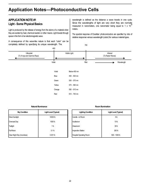
<strong>Application</strong> <strong>Notes—Photoconductive</strong> <strong>Cells</strong><br />
APPLICATION NOTE #1<br />
Light - Some Physical Basics<br />
Light is produced by the release of energy from the atoms of a material when<br />
they are excited by heat, chemical reaction or other means. Light travels through<br />
space in the form of an electromagnetic wave.<br />
A consequence of this wave-like nature is that each “color” can be<br />
completely defined by specifying its unique wavelength. The<br />
400<br />
wavelength is defined as the distance a wave travels in one cycle.<br />
Since the wavelengths of light are very short they are normally<br />
measured in nanometers, one nanometer being equal to 1 x 10 -9<br />
meters.<br />
The spectral response of Excelitas’ photoconductors are specified by lots of<br />
relative response versus wavelength (color) for various material types.<br />
Ultraviolet Visible Light Infrared<br />
(To X-rays and Gamma Rays) (To Radar Waves)<br />
700<br />
Violet Red Wavelength<br />
Violet Below 450 nm<br />
Blue 450 - 500 nm<br />
Green 500 - 570 nm<br />
Yellow 570 - 590 nm<br />
Orange 590 - 610 nm<br />
Red 610 - 700 nm<br />
Natural Illuminance Room Illumination<br />
Sky Condition Light Level (Typical) Lighting Condition Light Level (Typical)<br />
Direct Sunlight 10000 fc Candle - Lit Room 5 fc<br />
Overcast Day 1000 fc Auditorium 10 fc<br />
Twilight 1 fc Classroom 30 fc<br />
Full Moon 0.1 fc Inspection Station 250 fc<br />
Clear Night Sky (moonless) 0.001 fc Hospital Operating Room 500 - 1000 fc<br />
22
<strong>Application</strong> <strong>Notes—Photoconductive</strong> <strong>Cells</strong><br />
APPLICATION NOTE #2<br />
Light Resistance Measurement Techniques<br />
The light resistance or “on” resistance (RON) of a photoconductor cell<br />
is defined as the resistance of the cell as measured at a special light<br />
level using a light source with a known output spectrum. Furthermore,<br />
the cell must be “light adapted” for a specific period of time at an<br />
established level of illumination in order to achieve repeatable results.<br />
The industry standard light source used for light resistance<br />
measurements is a tungsten filament lamp operating at a color<br />
temperature of 2850 K. Specifying the 2850 K color temperature for the light<br />
source fixes the spectral output (i.e. the tungsten filament light has fixed<br />
amounts of blue, green, red, and infrared light).<br />
For consistency and ease of comparing different cells, Excelitas lists light<br />
resistance values for its photocells at two standard light levels: 2 fc<br />
(footcandles) and at 10 lux. The footcandle is the old, historical unit for<br />
measuring light intensity and is defined as the illumination produced<br />
when the light from one standard candle falls normally on a surface at a<br />
distance of one foot. The lux (the metric unit of light measurement) is the<br />
illumination produced when the light from one candle falls normally on a<br />
surface of one meter. The conversion between footcandle and lux. is as<br />
follows:<br />
1.0 fc = 10.76 lux<br />
1.0 lux = 0.093 fc<br />
As explained in the section on “Selecting a Photocell”, the “light history”<br />
effect necessitates the pre-conditioning of the cell before a light resistance<br />
measurement is made. Excelitas stores all cells at room temperature for 16<br />
hours minimum at 30 - 50 fc (about 320 - 540 lux) prior to making the test<br />
measurement.<br />
Sometimes the design engineer or user does not have access to the<br />
precision measurement equipment necessary to determine the light levels<br />
or light intensities of the application. Should this prove to be a problem,<br />
calibrated photocell samples with individual data can be provided by<br />
Excelitas.<br />
23<br />
APPLICATION NOTE #3<br />
Spectral Output of Common Light Sources<br />
Incandescent lamps can be considered as black body radiators whose spectral<br />
output is dependent on their color temperature. The sun has approximately<br />
the same spectral radiation distribution as that of a black body @ 5900 K.<br />
However, as viewed from the surface of the earth, the sun's spectrum contains<br />
H2O and CO2 absorption bands.<br />
Black Body Sources Output vs. Wavelength<br />
Fluorescent lamps exhibit a broad band spectral output with narrow peaks<br />
in certain parts of the spectrum. Shown below is a plot of the light output of a<br />
typical daylight type fluorescent tube.<br />
Fluorescent Lamp Output vs. Wavelength<br />
Due to their long operating lifetimes, small size, low power<br />
consumption, and the fact they generate little heat, LEDs are the light<br />
sources of choice in many applications. When biased in the forward<br />
direction LEDs emit light that is very narrow in spectral bandwidth (light of one<br />
color). The “color” of the light emitted depends on which semiconductor<br />
material was used for the LED.
<strong>Application</strong> <strong>Notes—Photoconductive</strong> <strong>Cells</strong><br />
LED Light Sources<br />
LED Type Color λP<br />
GaP GREEN 569 nm<br />
GaAsP/GaP YELLOW 585 nm<br />
GaAsP/GaP ORANGE 635 nm<br />
GaAsP/GaAs RED 655 nm<br />
AIGaAs RED 660 nm<br />
GaP/GaP RED 697 nm<br />
GaAIAs INFRARED 880 nm<br />
GaAs INFRARED 940 nm<br />
APPLICATION NOTE #4<br />
Spectral Matching of LEDs and<br />
Photoconductive Types<br />
Since light sources and light detectors are almost always used<br />
together the designer must take into consideration the optical coupling<br />
of this system or the ability of the detector to “see” the light source.<br />
In order to have good optical coupling between the emitter and the<br />
conductor the spectral output of the light source must, to some degree, overlap<br />
the spectral response of the detector. If the design involves the use of a light<br />
source with a broad band spectral output the designer is assured that the<br />
photocell will have good response to the light. This may not be the case when<br />
an LED light source is employed. LEDs emit their light within a very narrow<br />
spectral band so that they are often considered to be emitting at only on<br />
(peak) wavelength.<br />
Spectral matching factors were calculated for a number of different LEDs<br />
and the photoconductor material types manufactured by Excelitas.<br />
Each matching factor was derived by multiplying the detector response<br />
curves by the LED spectral output curve and then measuring the resulting<br />
area.<br />
24<br />
The LED/photocell matching factors listed are independent of power<br />
output from the LEDs. In order to get a real feel on how well any LED/<br />
photocell pair couple together, the power output from the LED at a<br />
particular forward drive current must be considered.<br />
Normalized LED/Photocell Matching<br />
(nm) Type Ø Material Type 3 Material<br />
LED Type λP<br />
GaP 569 39% 40%<br />
GaAsP/GaP 58 60% 52%<br />
GaAsP/GaP 635 49% 38%<br />
GaAsP/GaAs 655 31% 27%<br />
AIGaAs 66 31% 27%<br />
GaP/GaP 697 47% 31%<br />
GaAIAs 880 — —<br />
GaAs 940 — —<br />
The intensity of the light being emitted by visible LEDs is often given in<br />
units of millicandela. Millicandela is photometric unit of measure which<br />
assumes the human eye as the detector. For most detectors other than<br />
the human eye the most convenient system for measurement is the<br />
radiometric system. Listed below is the typical light power output of<br />
some LEDs measured at two different forward drive currents. Note that<br />
LEDs of a given type can show a 5:1 manufacturing spread in power<br />
outputs.<br />
LED Type Color λP (nm)<br />
Power Output<br />
If = 1 mA If = 10 mA<br />
GaP GREEN 569 nm 1.2 µW 24.1 µW<br />
GaAsP/GaP YELLOW 585 nm 0.3 µW 26.2 µW<br />
GaAsP/GaP ORANGE 635 nm 3.2 µW 101.9 µW<br />
GaAsP/GaAs RED 655 nm 6.2 µW 102.1 µW<br />
AIGaAs RED 660 nm 33.8 µW 445.1 µW<br />
GaP/GaP RED 697 nm 54.3 µW 296.2 µW<br />
GaAIAs INFRARED 880 nm 76.8 µW 1512.3 µW<br />
GaAs INFRARED 940 nm 35.5 µW 675.0 µW
<strong>Application</strong> <strong>Notes—Photoconductive</strong> <strong>Cells</strong><br />
Factoring in the power outputs of the LEDs, in this case at a forward<br />
drive current of 10 ma, coupling factors (matching factor multiplied by<br />
power output) for the various LED/material type combinations can be<br />
generated.<br />
Normalized LED/Photocell Coupling Factors @ 10 mA<br />
LED Type<br />
(nm)<br />
λP<br />
Type Ø Type 3<br />
GaP 569 3% 3%<br />
GaAsP/GaP 58 5% 5%<br />
GaAsP/GaP 635 17% 13%<br />
GaAsP/GaAs 655 11% 9%<br />
AIGaAs 66 47% 35%<br />
GaP/GaP 697 47% 31%<br />
GaAIAs 880 — —<br />
GaAs 940 — —<br />
Once gain, this data is intended as a general guide. LED power outputs<br />
can vary 5:1 between manufacturer lots.<br />
APPLICATION NOTE #5<br />
Assembly Precautions<br />
When soldering the cell leads take all measures possible to limit the<br />
amount of heating to the photocell. The maximum recommended<br />
soldering temperature is 250°C with a solder duration of 5 seconds. Heat<br />
sink the LEDs if possible. Keep soldering iron 1/16 inch (1.6 mm) minimum from<br />
base of package when soldering.<br />
Avoid chemicals which can cause metal corrosion. Do not clean the plastic<br />
coated cells with organic solvents (ketone types). Check with factory for<br />
specific cleaning recommendations.<br />
Finally refrain from storing the cells under high temperature and/or<br />
humidity conditions. If cells are stored in the dark for any length of time<br />
please “light adept” before testing (see section on Light History Effect).<br />
Storage in the dark will change both the sensitivity and decay time of<br />
the cell.<br />
25<br />
APPLICATION NOTE #6<br />
A Low Cost Light Source for Measuring<br />
Photocells<br />
The Light Source used in the measurement of photocell resistance must<br />
be characterized for intensity and spectral composition. Excelitas uses<br />
a tungsten filament lamp having a spectral output approximating a black<br />
body @ 2850 K with a known candlepower output at a specified voltage and<br />
current.<br />
While calibrated lamps of this type are available from the National<br />
Institute of Standards and Technology (formerly NBS) and private<br />
testing labs, a low cost alternative is to use a 100 W, inside frosted,<br />
tungsten filament lamp available from any home or hardware store.<br />
Such a lamp operated at 120 VAC will produce approximately 90<br />
candlepower (cp) of illumination and a color temperature of 2700 K to<br />
2800 K.<br />
The relationship between candlepower and footcandle is:<br />
candle power<br />
footcandle = ---------------------------------------<br />
(distance in feet) 2<br />
Since this equation assumes a point source of light, the distance<br />
between lamp and detector should be at least five times the lamp<br />
diameter.<br />
There are some characteristics of incandescent lamps which should be<br />
noted:<br />
1. Color temperature increases with increasing wattage.<br />
2. When operated at a constant current, light output rises with time.<br />
3. When operated at a constant voltage, light decreases with time,<br />
especially during the first few hours.
<strong>Application</strong> <strong>Notes—Photoconductive</strong> <strong>Cells</strong><br />
APPLICATION NOTE #7<br />
How to Specify a Low Cost Photocell<br />
Sometimes the demands of the application such as power dissipation,<br />
“on” resistance, voltage, temperature coefficient, etc. limit the selection<br />
of the photocell to one particular device. However, more common is the<br />
case where any number of photocell types can be used, especially if<br />
minor changes are undertaken at an early enough point in the circuit<br />
design. In these cases, price is often the deciding factor.<br />
Many factors influence price. In order to give some guidance and weight to<br />
these factors the reader is referred to the following table which is meant to<br />
serve as a general guide.<br />
Lower Cost Factor Higher Cost<br />
Plastic Packaging Glass/Metal<br />
Broad Resistance Range Narrow<br />
Small Package Size Large<br />
Open Order with Scheduling Released Orders<br />
Scheduled Releases<br />
Standard Tests Testing Special Tests<br />
26