In the box Installation & operating instructions - Aspen Pumps
In the box Installation & operating instructions - Aspen Pumps
In the box Installation & operating instructions - Aspen Pumps

You also want an ePaper? Increase the reach of your titles
YUMPU automatically turns print PDFs into web optimized ePapers that Google loves.
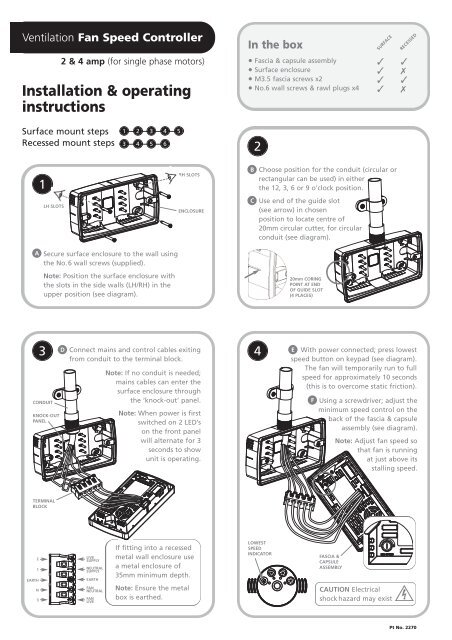
Ventilation Fan Speed Controller<br />
A<br />
1<br />
LH SLOTS<br />
2 & 4 amp (for single phase motors)<br />
<strong>In</strong>stallation & <strong>operating</strong><br />
<strong>instructions</strong><br />
Surface mount steps<br />
Recessed mount steps<br />
1 2 3 4<br />
3 4 5 6<br />
Secure surface enclosure to <strong>the</strong> wall using<br />
<strong>the</strong> No.6 wall screws (supplied).<br />
Note: Position <strong>the</strong> surface enclosure with<br />
<strong>the</strong> slots in <strong>the</strong> side walls (LH/RH) in <strong>the</strong><br />
upper position (see diagram).<br />
5<br />
RH SLOTS<br />
ENCLOSURE<br />
D 3 Connect mains and control cables exiting 4<br />
CONDUIT<br />
KNOCK-OUT<br />
PANEL<br />
TERMINAL<br />
BLOCK<br />
2<br />
1<br />
EARTH<br />
N<br />
3<br />
from conduit to <strong>the</strong> terminal block.<br />
LIVE<br />
SUPPLY<br />
NEUTRAL<br />
SUPPLY<br />
EARTH<br />
FAN<br />
NEUTRAL<br />
FAN<br />
LIVE<br />
Note: If no conduit is needed;<br />
mains cables can enter <strong>the</strong><br />
surface enclosure through<br />
<strong>the</strong> ‘knock-out’ panel.<br />
Note: When power is first<br />
switched on 2 LED’s<br />
on <strong>the</strong> front panel<br />
will alternate for 3<br />
seconds to show<br />
unit is <strong>operating</strong>.<br />
If fitting into a recessed<br />
metal wall enclosure use<br />
a metal enclosure of<br />
35mm minimum depth.<br />
Note: Ensure <strong>the</strong> metal<br />
<strong>box</strong> is ear<strong>the</strong>d.<br />
<strong>In</strong> <strong>the</strong> <strong>box</strong><br />
B<br />
C<br />
Fascia & capsule assembly<br />
Surface enclosure<br />
M3.5 fascia screws x2<br />
No.6 wall screws & rawl plugs x4<br />
2<br />
Choose position for <strong>the</strong> conduit (circular or<br />
rectangular can be used) in ei<strong>the</strong>r<br />
<strong>the</strong> 12, 3, 6 or 9 o’clock position.<br />
Use end of <strong>the</strong> guide slot<br />
(see arrow) in chosen<br />
position to locate centre of<br />
20mm circular cutter, for circular<br />
conduit (see diagram).<br />
LOWEST<br />
SPEED<br />
INDICATOR<br />
20mm CORING<br />
POINT AT END<br />
OF GUIDE SLOT<br />
(4 PLACES)<br />
E With power connected; press lowest<br />
speed button on keypad (see diagram).<br />
The fan will temporarily run to full<br />
speed for approximately 10 seconds<br />
(this is to overcome static friction).<br />
F<br />
SURFACE<br />
✓ ✓<br />
✓ ✗<br />
✓ ✓<br />
✓ ✗<br />
Using a screwdriver; adjust <strong>the</strong><br />
minimum speed control on <strong>the</strong><br />
back of <strong>the</strong> fascia & capsule<br />
assembly (see diagram).<br />
FASCIA &<br />
CAPSULE<br />
ASSEMBLY<br />
Note: Adjust fan speed so<br />
that fan is running<br />
at just above its<br />
stalling speed.<br />
CAUTION Electrical<br />
shock hazard may exist<br />
RECESSED<br />
Pt No. 2270
G<br />
H<br />
5<br />
Push terminal block firmly into<br />
pegs (2 position options - surface<br />
mount only) until seated down<br />
firmly. Ensure that <strong>the</strong> cables are<br />
laid in <strong>the</strong> most suitable place<br />
to prevent pinching or straining<br />
of <strong>the</strong> connections.<br />
Locate <strong>the</strong> fascia and capsule<br />
assembly onto <strong>the</strong> enclosure<br />
and secure using <strong>the</strong> 2 screws<br />
supplied.<br />
Note: The fascia<br />
and capsule<br />
assembly should<br />
be fitted in <strong>the</strong><br />
orientation shown.<br />
LH TERMINAL<br />
BLOCK POSITION<br />
RH TERMINAL<br />
BLOCK POSITION<br />
Controller operation overview<br />
Minimum fan speed<br />
The unit is designed for continuous operation.<br />
Made in Great Britain<br />
FASCIA &<br />
CAPSULE<br />
ASSEMBLY<br />
Maximum fan speed<br />
On/off<br />
6<br />
I The fascia and capsule assembly should be fitted<br />
in <strong>the</strong> orientation shown.<br />
Note: Use minimum 35mm depth <strong>box</strong>.<br />
METAL WALL<br />
ENCLOSURE<br />
Electrical specification<br />
Model VFSC/2 230V 2A 50Hz fused<br />
Model VFSC/4 230V 4A 50Hz fused<br />
Normal equipment <strong>operating</strong> is 0 to 40°C ambient<br />
At maximum current continuous operation at<br />
30°C ambient<br />
IP33 rated<br />
IMPORTANT Before undertaking any work on this unit<br />
ensure electrical supply is disconnected. The installation<br />
must be carried out by suitably qualified personnel in<br />
accordance with all <strong>the</strong> appropriate statutory and<br />
governing regulations.<br />
REPLACING THE FUSE The unit is fitted with a cartridge<br />
fuse. To replace <strong>the</strong> fuse, which is located in <strong>the</strong> back of<br />
fascia and capsule assembly: Remove fascia and capsule<br />
assembly, remove cartridge fuse and replace with identical<br />
specification fuse - 20mm antisurge ceramic fuse 2 amp or<br />
4 amp depending on model.<br />
COMPLIES WITH THE FOLLOWING STANDARD<br />
(89/336/EEC amended by 92/31/EEC) (73/23/EEC amended by 93/68/EEC)<br />
(89/392/EEC amended by 91/368/EEC) (93/44/EEC amended by 93/68/EEC)<br />
(BSEN 60335-1: 2002 part 1) (BSEN 60335-2-80: 2003)<br />
<strong>Aspen</strong> <strong>Pumps</strong> Apex Way<br />
Hailsham East Sussex<br />
BN27 3WA UK<br />
T: +44 (0) 1323 848 842<br />
F: +44 (0) 1323 848 847<br />
E: sales@aspenpumps.com<br />
www.aspenpumps.com