


Create successful ePaper yourself
Turn your PDF publications into a flip-book with our unique Google optimized e-Paper software.
34<br />
I N C R E M E N T A L<br />
Electrical output signals<br />
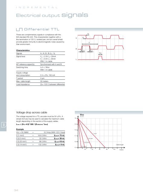
Differential TTL<br />
These are complementary signals in compliance with the<br />
EIA standard RS-422. This characteristic together with a<br />
line termination of 120 Ω, twisted pair, and an overall shield<br />
provide greater immunity to electromagnetic noise caused by<br />
their environment.<br />
Characteristics<br />
Signals A, /A, B, /B, I0, / I0<br />
Signal level V ≥ 2.5V I = 20mA<br />
H H<br />
V ≤ 0.5V I = 20mA<br />
L L<br />
With 1 m cable<br />
90º reference signal (I0) Synchronized with A and B<br />
Switching time<br />
Supply voltage<br />
t+/t-< 30ns<br />
With 1 m cable<br />
and consumption 5 V ± 5%, 100 mA<br />
T period 4 µm<br />
Max. cable length 50 meters<br />
Load impedance Zo= 120 Ω between differential<br />
Voltage drop across cable<br />
The voltage required for a TTL encoder must be 5V ±5%. A<br />
simple formula may be used to calculate the maximum cable<br />
length depending on the section of the supply cables.<br />
Lmax = (VCC-4.5)* 500 / (ZCABLE/Km* IMAX)<br />
Example<br />
Vcc = 5V, IMAX = 0.2 Amp (With 120 Ω load)<br />
Z (1 mm2 ) = 16.6 Ω/Km (Lmax= 75 m)<br />
Z (0.5 mm2 ) = 32 Ω/Km (Lmax= 39 m)<br />
Z (0.25 mm2 ) = 66 Ω/Km (Lmax=19 m)<br />
Z (0.14 mm2 ) = 132 Ω/Km (Lmax= 9 m)<br />
A<br />
B<br />
Io<br />
VL<br />
VH<br />
T<br />
t+ t-<br />
T/4<br />
Cable length<br />
meters


