UL600LSDM Magnetic Lock Manual - Fast Access Security Corp.
UL600LSDM Magnetic Lock Manual - Fast Access Security Corp.
UL600LSDM Magnetic Lock Manual - Fast Access Security Corp.

Create successful ePaper yourself
Turn your PDF publications into a flip-book with our unique Google optimized e-Paper software.
Door<br />
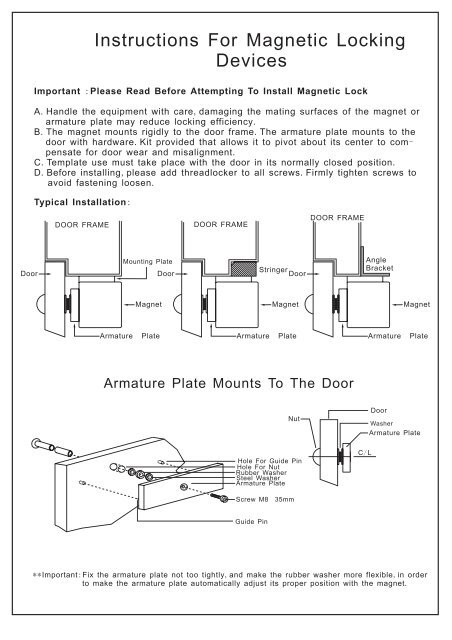
Instructions For <strong>Magnetic</strong> <strong>Lock</strong>ing<br />
Devices<br />
Important : Please Read Before Attempting To Install <strong>Magnetic</strong> <strong>Lock</strong><br />
A. Handle the equipment with care, damaging the mating surfaces of the magnet or<br />
armature plate may reduce locking efficiency.<br />
B. The magnet mounts rigidly to the door frame. The armature plate mounts to the<br />
door with hardware. Kit provided that allows it to pivot about its center to com-<br />
pensate for door wear and misalignment.<br />
C. Template use must take place with the door in its normally closed position.<br />
D. Before installing, please add threadlocker to all screws. Firmly tighten screws to<br />
avoid fastening loosen.<br />
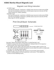
Typical Installation:<br />
DOOR FRAME<br />
Mounting Plate<br />
Magnet<br />
Armature Plate<br />
Door<br />
DOOR FRAME<br />
Stringer<br />
Door<br />
Magnet<br />
Armature Plate<br />
DOOR FRAME<br />
Armature Plate Mounts To The Door<br />
Hole For Guide Pin<br />
Hole For Nut<br />
Rubber Washer<br />
Steel Washer<br />
Armature Plate<br />
Screw M8 35mm<br />
Guide Pin<br />
Nut<br />
Angle<br />
Bracket<br />
C/ L<br />
Magnet<br />
Armature Plate<br />
Door<br />
Washer<br />
Armature Plate<br />
** Important: Fix the armature plate not too tightly, and make the rubber washer more flexible, in order<br />
to make the armature plate automatically adjust its proper position with the magnet.
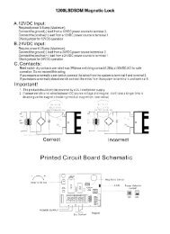
<strong>Magnetic</strong> <strong>Lock</strong> Wiring Instructions<br />
A.12VDC Input:<br />
Required power 0.5 amp (Maximum).<br />
Connect the ground(-) lead from a 12VDC power source to terminal 2.<br />
Connect the positive(+) lead from a 12VDC power source to terminal 1.<br />
Check jumper for 12VDC operation.<br />
B.24VDC input:<br />
Require power 0.25 amp (Maximum).<br />
Connect the ground(-) lead from a 24VDC power source in terminal 2.<br />
Connect the positive(+) lead from a 24VDC power source to terminal 1.<br />
Check jumper for 24VDC operation.<br />
C.Contacts:<br />
Reed switch dry contacts are rated max 3W(max switching contact 0.25A) at 30VDC/AC for safe<br />
operation. Do not exceed this rating.<br />
If you require a normally open switch,connect the wires from the system to terminal 4 and terminal 3.<br />
If you require a normally closed switch,connect the wires from the system to terminal 4 and terminal 5.<br />
Important!<br />
1. The product should only be powered by a UL listed power supply.<br />
2. If power switch is not wired between DC source voltage and magnet ,it will take a longer time to<br />
de-energize the magnet simulating residual magnetism.(see below)<br />
AC<br />
110V<br />
OR<br />
220V<br />
SWITCHOR<br />
SOLID STATE<br />
SWITCHING DEVICE<br />
DC 12V<br />
OR 24V<br />
+<br />
-<br />
AC<br />
110V<br />
OR<br />
220V<br />
SWITCHOR<br />
SOLID STATE<br />
SWITCHING DEVICE<br />
DC 12V<br />
OR 24V<br />
Correct Incorrect<br />
Printed Circuit Board Schematic<br />
POWER SUPPLY<br />
Timer<br />
<strong>Lock</strong> Status Sensor<br />
+<br />
-<br />
1<br />
2<br />
3<br />
4<br />
5<br />
RY1<br />
- +<br />
NO<br />
C<br />
NC<br />
+<br />
IC1<br />
G<br />
Power Selector<br />
Jumper<br />
LED<br />
Magnet<br />
BUZEER<br />
12VDC<br />
24VDC<br />
Mag Bond Sensor<br />
+<br />
-<br />
WG007-F