Steam Digest 2002 - CiteSeerX
Steam Digest 2002 - CiteSeerX
Steam Digest 2002 - CiteSeerX

You also want an ePaper? Increase the reach of your titles
YUMPU automatically turns print PDFs into web optimized ePapers that Google loves.
<strong>Steam</strong> <strong>Digest</strong> <strong>2002</strong><br />
Because of the durability of the components,<br />
this system can improve the symptom where a<br />
self-contained steam trap has been regularly<br />
damaged from severe water hammer, but it does<br />
not correct the cause. In this sense, it is only a<br />
band-aid, and additional symptoms of corrosion<br />
and production variance from the control<br />
value will not be corrected by this option.<br />
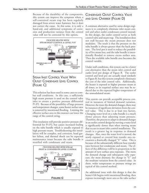
STEAM INLET CONTROL VALVE WITH<br />
OUTLET CONDENSATE LEVEL CONTROL<br />
(FIGURE C)<br />
This solution has been used in some cases to combat<br />
stall conditions. In this case, a sufficiently<br />
high steam pressure is used on the control valve<br />
inlet to ensure a positive pressure differential<br />
P1:P2. Because of the possibility of large pressure<br />
and temperature changes, some heater surface area<br />
is removed by intentional flooding. Limiting the<br />
effective surface area in this manner can lower the<br />
range of the control swing.<br />
This insulation will provide positive pressure differential<br />
for P1:P2, but causes increased fouling<br />
on the tube bundle which is usually exposed to<br />
high pressure steam. Troubleshooting this installation<br />
will be complex, and corrosion, head gasket<br />
failure, and thermal shock can be expected<br />
maintenance issues because the tube bundle is<br />
stratified with condensate and steam.<br />
An Analysis of <strong>Steam</strong> Process Heater Condensate Drainage Options<br />
CONDENSATE OUTLET CONTROL VALVE<br />
AND LEVEL OVERRIDE (FIGURE D)<br />
A common alternative used by some design engineers<br />
is to completely eliminate inlet steam control<br />
and select outlet condensate control instead.<br />
In this design, the outlet control serves as both<br />
control valve and steam trap. The installation does<br />
not stall because the steam pressure does not<br />
modulate. The result is that the pressure on the<br />
tube bundle is always greater than the back pressure.<br />
The level pot is used to reduce the possibility<br />
of live steam loss, and the tube bundle is intentionally<br />
flooded to remove excess surface area.<br />
Then the available tube bundle area becomes the<br />
control variable.<br />
Under stall conditions, this system can be a lower<br />
cost alternative than the steam inlet control and<br />
outlet level pot design of Figure B. The outlet<br />
control and level pot are actually sized similarly<br />
to Figure B, but this system completely eliminates<br />
the cost of the inlet control valve. Additionally,<br />
the heater is exposed to higher pressure steam at<br />
all times, so its required surface area may be reduced<br />
due to the expected higher temperature of<br />
the unmodulated steam.<br />
This system can provide acceptable process control<br />
in instances of limited demand variation.<br />
However, the more the demand changes, there may<br />
be instances of significant deviation from the control<br />
value. This is due to at least two factors.<br />
Changing water level on a tube bundle is a much<br />
slower process than adjusting steam pressure.<br />
Therefore, the process to adapt to demand changes<br />
in an outlet control design by moving a water level<br />
is significantly slower than when moving steam<br />
that occurs in steam inlet control installations. The<br />
result is a greater lag in response to demand<br />
changes. Also, once the water level is moved, the<br />
newly exposed or covered heat transfer area encounters<br />
a drastically changed “U” value. This is<br />
because of the substantially different heat transfer<br />
rates between hot condensate and steam. The effects<br />
of this difference will be in proportion to the<br />
amount of new surface area exposure. The more<br />
the demand change and subsequent tube exposure,<br />
the more dramatic the change in “U” and<br />
the resultant variation from the control value. In<br />
short, wider temperature or pressure swings are<br />
typical of this control method.<br />
An additional issue with this design is that the<br />
heater’s life begins with intentional flooding, then<br />
exposes increasingly more area as the tube surface<br />
25