Coil-Cut Switching for Humbuckers - The Blue Guitar
Coil-Cut Switching for Humbuckers - The Blue Guitar
Coil-Cut Switching for Humbuckers - The Blue Guitar

You also want an ePaper? Increase the reach of your titles
YUMPU automatically turns print PDFs into web optimized ePapers that Google loves.
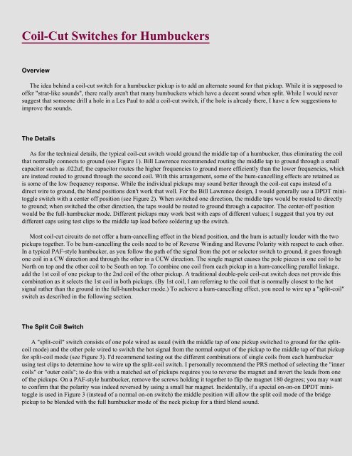
<strong>Coil</strong>-<strong>Cut</strong> Switches <strong>for</strong> <strong>Humbuckers</strong><br />
Overview<br />
<strong>The</strong> idea behind a coil-cut switch <strong>for</strong> a humbucker pickup is to add an alternate sound <strong>for</strong> that pickup. While it is supposed to<br />
offer "strat-like sounds", there really aren't that many humbuckers which have a decent sound when split. While I would never<br />
suggest that someone drill a hole in a Les Paul to add a coil-cut switch, if the hole is already there, I have a few suggestions to<br />
improve the sounds.<br />
<strong>The</strong> Details<br />
As <strong>for</strong> the technical details, the typical coil-cut switch would ground the middle tap of a humbucker, thus eliminating the coil<br />
that normally connects to ground (see Figure 1). Bill Lawrence recommended routing the middle tap to ground through a small<br />
capacitor such as .022uf; the capacitor routes the higher frequencies to ground more efficiently than the lower frequencies, which<br />
are instead routed to ground through the second coil. With this arrangement, some of the hum-cancelling effects are retained as<br />
is some of the low frequency response. While the individual pickups may sound better through the coil-cut caps instead of a<br />
direct wire to ground, the blend positions don't work that well. For the Bill Lawrence design, I would generally use a DPDT minitoggle<br />
switch with a center off position (see Figure 2). When switched one direction, the middle taps would be routed to directly<br />
to ground; when switched the other direction, the taps would be routed to ground through a capacitor. <strong>The</strong> center-off position<br />
would be the full-humbucker mode. Different pickups may work best with caps of different values; I suggest that you try out<br />
different caps using test clips to the middle tap lead be<strong>for</strong>e soldering up the switch.<br />
Most coil-cut circuits do not offer a hum-cancelling effect in the blend position, and the hum is actually louder with the two<br />
pickups together. To be hum-cancelling the coils need to be of Reverse Winding and Reverse Polarity with respect to each other.<br />
In a typical PAF-style humbucker, as you follow the path of the signal from the pot or selector switch to ground, it goes through<br />
one coil in a CW direction and through the other in a CCW direction. <strong>The</strong> single magnet causes the pole pieces in one coil to be<br />
North on top and the other coil to be South on top. To combine one coil from each pickup in a hum-cancelling parallel linkage,<br />
add the 1st coil of one pickup to the 2nd coil of the other pickup. A traditional double-pole coil-cut switch does not provide this<br />
combination as it selects the 1st coil in both pickups. (By 1st coil, I am referring to the coil that is normally closest to the hot<br />
signal rather than the ground in the full-humbucker mode.) To achieve a hum-cancelling effect, you need to wire up a "split-coil"<br />
switch as described in the following section.<br />
<strong>The</strong> Split <strong>Coil</strong> Switch<br />
A "split-coil" switch consists of one pole wired as usual (with the middle tap of one pickup switched to ground <strong>for</strong> the splitcoil<br />
mode) and the other pole wired to switch the hot signal from the normal output of the pickup to the middle tap of that pickup<br />
<strong>for</strong> split-coil mode (see Figure 3). I'd recommend testing out the different combinations of single coils from each humbucker<br />
using test clips to determine how to wire up the split-coil switch. I personally recommend the PRS method of selecting the "inner<br />
coils" or "outer coils"; to do this with a matched set of pickups requires you to reverse the magnet and invert the leads from one<br />
of the pickups. On a PAF-style humbucker, remove the screws holding it together to flip the magnet 180 degrees; you may want<br />
to confirm that the polarity was indeed reversed by using a small bar magnet. Incidentally, if a special on-on-on DPDT minitoggle<br />
is used in Figure 3 (instead of a normal on-on switch) the middle position will allow the split coil mode of the bridge<br />
pickup to be blended with the full humbucker mode of the neck pickup <strong>for</strong> a third blend sound.
<strong>The</strong> Wiring Diagrams:<br />
To Translate SD Color Codes:<br />
Back to my <strong>Guitar</strong> Wiring Page<br />
Back to my Home Page<br />
colorcod.pdf
To convert color codes <strong>for</strong> other brand pickups:<br />
[A] __( ))))))))))))__ [B]<br />
[D] __( ))))))))))))__ [C]<br />
(adapted from Stewart-MacDonald's web site)<br />
A B C D<br />
Seymour Duncan Black White Red Green<br />
DiMarzio Red Green White Black<br />
Gibson Black Green White Red<br />
PRS Neck White Red >>> > Ground<br />
Series/In Phase [Non-Humbucking]<br />
A -> Hot(+); B D; C -> Ground<br />
Parallel/Out-of-Phase ["Dual Sound" Linkage]**<br />
A & C -> Hot(+); B & D -> Ground<br />
Parallel/In Phase [Non-Humbucking]<br />
A & D -> Hot(+); B & C -> Ground<br />
* Normal humbucker wiring <strong>for</strong> full sound.<br />
** Alt. humbucking wiring <strong>for</strong> a thinner sound.