Application of Motionless Mixers in Gas Purification – A Case Study
Application of Motionless Mixers in Gas Purification – A Case Study
Application of Motionless Mixers in Gas Purification – A Case Study

Create successful ePaper yourself
Turn your PDF publications into a flip-book with our unique Google optimized e-Paper software.
<strong>Application</strong> <strong>of</strong> <strong>Motionless</strong> <strong>Mixers</strong> <strong>in</strong> <strong>Gas</strong> <strong>Purification</strong> <strong>–</strong> A <strong>Case</strong> <strong>Study</strong><br />
A. Ujhidy 1 , Gy. Bucsky 1 , J. Gyenis 1<br />
1 University <strong>of</strong> Kaposvár, Research Institute <strong>of</strong> Chemical and Process Eng<strong>in</strong>eer<strong>in</strong>g,<br />
Veszprém, H-8200 Egyetem u. 2, Hungary<br />
Summary <strong>–</strong> The lecture gives a review on the application <strong>of</strong> motionless<br />
mixers <strong>in</strong> gas purification, where wet dust separation is carried out by<br />
water circulation trough vertical tubes filled with FixMix TM motionless<br />
mixer elements. Dusty gas and water are flow<strong>in</strong>g downwards, co-currently.<br />
Solids phase is filtered cont<strong>in</strong>uously from the slurry.<br />
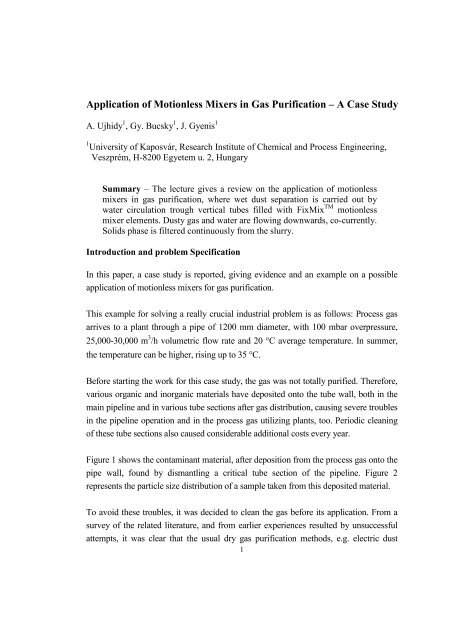
Introduction and problem Specification<br />
In this paper, a case study is reported, giv<strong>in</strong>g evidence and an example on a possible<br />
application <strong>of</strong> motionless mixers for gas purification.<br />
This example for solv<strong>in</strong>g a really crucial <strong>in</strong>dustrial problem is as follows: Process gas<br />
arrives to a plant through a pipe <strong>of</strong> 1200 mm diameter, with 100 mbar overpressure,<br />
25,000-30,000 m 3 /h volumetric flow rate and 20 °C average temperature. In summer,<br />
the temperature can be higher, ris<strong>in</strong>g up to 35 °C.<br />
Before start<strong>in</strong>g the work for this case study, the gas was not totally purified. Therefore,<br />
various organic and <strong>in</strong>organic materials have deposited onto the tube wall, both <strong>in</strong> the<br />
ma<strong>in</strong> pipel<strong>in</strong>e and <strong>in</strong> various tube sections after gas distribution, caus<strong>in</strong>g severe troubles<br />
<strong>in</strong> the pipel<strong>in</strong>e operation and <strong>in</strong> the process gas utiliz<strong>in</strong>g plants, too. Periodic clean<strong>in</strong>g<br />
<strong>of</strong> these tube sections also caused considerable additional costs every year.<br />
Figure 1 shows the contam<strong>in</strong>ant material, after deposition from the process gas onto the<br />
pipe wall, found by dismantl<strong>in</strong>g a critical tube section <strong>of</strong> the pipel<strong>in</strong>e. Figure 2<br />
represents the particle size distribution <strong>of</strong> a sample taken from this deposited material.<br />
To avoid these troubles, it was decided to clean the gas before its application. From a<br />
survey <strong>of</strong> the related literature, and from earlier experiences resulted by unsuccessful<br />
attempts, it was clear that the usual dry gas purification methods, e.g. electric dust<br />
1
precipitation, gas cool<strong>in</strong>g methods, etc. could not be used to solve this problem. The<br />
only possibility was to apply a wet method, namely scrubb<strong>in</strong>g the gas by water. Our<br />
task was to establish such a gas wash<strong>in</strong>g method and equipment, which has the<br />
follow<strong>in</strong>g advantages: simple, reliable, can be scaled-up easily, has small pressure drop<br />
aga<strong>in</strong>st the gas flow, and where the removed solids is readily separable from the<br />
recycled liquid phase.<br />
Laboratory tests<br />
For model tests, laboratory-scale equipment was assembled for contact<strong>in</strong>g <strong>of</strong> air and<br />
water <strong>in</strong> co-current streams, us<strong>in</strong>g motionless mixers. Another requirement was that the<br />
results <strong>of</strong> the laboratory tests had to be suitable for scal<strong>in</strong>g-up <strong>of</strong> the process and<br />
equipment. On the basis <strong>of</strong> our earlier experiences obta<strong>in</strong>ed with dry and wet dust<br />
separation, a glass tube with 20 mm i.d. and 2000 mm length was applied, equipped<br />
with a long str<strong>in</strong>g <strong>of</strong> tightly fitted FixMis TM motionless mixer elements. This<br />
laboratory-scale equipment is shown <strong>in</strong> Figure 3.<br />
Dur<strong>in</strong>g the experiments, the volumetric flow rate <strong>of</strong> air and the spr<strong>in</strong>kl<strong>in</strong>g <strong>in</strong>tensity<br />
were varied systematically. Pressure drop was measured and flow regimes and other<br />
conditions were observed. On the basis <strong>of</strong> measurements and observations, the optimal<br />
parameters <strong>of</strong> the process were determ<strong>in</strong>ed. These f<strong>in</strong>d<strong>in</strong>gs were also checked <strong>in</strong> the<br />
presence <strong>of</strong> f<strong>in</strong>e solids, dispersed as dust <strong>in</strong>to the <strong>in</strong>troduced air. For this, f<strong>in</strong>e lime<br />
hydrate and alum<strong>in</strong>a powders with particle size distribution between 1-5 micron were<br />
used.<br />
It is generally known that motionless mixers are passive process-<strong>in</strong>tensification tools,<br />
which, <strong>in</strong> contrast with usual stirrers, do not move themselves. Utiliz<strong>in</strong>g the pressure,<br />
the potential and k<strong>in</strong>etic energy <strong>of</strong> the stream<strong>in</strong>g phases, they create turbulence, relative<br />
displacements, attrition, multiple division and recomb<strong>in</strong>ation, and can also be used for<br />
contact<strong>in</strong>g <strong>of</strong> different phase elements. There are a number <strong>of</strong> different types <strong>of</strong><br />
motionless mixers, used ma<strong>in</strong>ly <strong>in</strong> tubes, but also <strong>in</strong> other devices e.g. <strong>in</strong> vessels and<br />
columns. Figure 4 shows helical motionless mixers with regards <strong>of</strong> their work<strong>in</strong>g<br />
mechanisms. The FixMix TM elements, used by us for these experiments belong to<br />
helical type mixers, similarly to the well-known Kenics static mixers. But, FixMix TM<br />
2
mixers have certa<strong>in</strong> specific features, namely: Each mixer elements succeed<strong>in</strong>g each<br />
other are tapered, i.e. contract<strong>in</strong>g along their lengths, are <strong>in</strong>cl<strong>in</strong><strong>in</strong>g relative to the tube<br />
axis, thus divid<strong>in</strong>g the tube cross section asymmetrically.<br />
On Figure 5, pressure drop <strong>of</strong> the experimental equipment is shown as a function <strong>of</strong><br />
spr<strong>in</strong>kl<strong>in</strong>g <strong>in</strong>tensity for various superficial gas flow rates.<br />
It has to be noticed that above 210,000 kg/m 2 h spr<strong>in</strong>kl<strong>in</strong>g <strong>in</strong>tensity, pulsation has<br />
arisen for all cases, which disturbed the normal operation <strong>of</strong> equipment. The curved<br />
arrows on the diagram show the start<strong>in</strong>g values <strong>of</strong> spr<strong>in</strong>kl<strong>in</strong>g <strong>in</strong>tensity, from where the<br />
<strong>in</strong>troduced dust particles became well wetted mak<strong>in</strong>g total separation <strong>of</strong> dust from the<br />
gas possible.<br />
From the <strong>in</strong>vestigation on laboratory-scale equipment, it was found that 17.7 m/s<br />
superficial gas flow rate and 50,000-150,000 kg/m 2 h spr<strong>in</strong>kl<strong>in</strong>g <strong>in</strong>tensity were optimal.<br />
For this, it was supposed that low water circulation is the ma<strong>in</strong> requirement, <strong>in</strong> order to<br />
decrease the necessary pump<strong>in</strong>g performance or electric energy consumption.<br />
First attempt to design <strong>in</strong>dustrial scale equipment<br />
To design an equipment <strong>in</strong> commercial scale, whose performance is determ<strong>in</strong>ed by the<br />
volumetric flow rate <strong>of</strong> the gas to be treated, the comb<strong>in</strong>ed utilization <strong>of</strong> hydrodynamic<br />
similarity and the so-called additive scal<strong>in</strong>g-up pr<strong>in</strong>ciples seemed to be appropriate. It<br />
means that tube diameter was <strong>in</strong>creased from 20 mm to 49 mm i.d., and the length <strong>of</strong><br />
tubes from 2 m to 3 m, keep<strong>in</strong>g the spr<strong>in</strong>kl<strong>in</strong>g <strong>in</strong>tensity and superficial gas velocity<br />
constant. Accord<strong>in</strong>g to our earlier experiments, it could be done without any risk <strong>of</strong><br />
operational troubles or reduction <strong>of</strong> their separation performance. Additive scal<strong>in</strong>g-up<br />
means the multiplication <strong>of</strong> the tubes work<strong>in</strong>g parallel to each other.<br />
By this way, a square cross-sectional equipment was designed with vertical bundle <strong>of</strong><br />
tubes filled with motionless mixers, ensur<strong>in</strong>g the conditions and parameters, which<br />
proved to be optimal dur<strong>in</strong>g the laboratory-scale <strong>in</strong>vestigations. With<strong>in</strong> this quadratic<br />
cross-section, altogether 218 tubes were necessary, spaced equidistantly <strong>in</strong> triangular<br />
network <strong>of</strong> a nearly square form tube-panel, along 15 rows. It means that there were 15<br />
3
tubes <strong>in</strong> every second rows, and 14 tubes <strong>in</strong> the next rows, alternatively. Consider<strong>in</strong>g<br />
the 0,41 m 2 total free cross-section <strong>of</strong> the 218 tubes <strong>of</strong> 49 mm i.d., and the quantity <strong>of</strong><br />
process gas used <strong>in</strong> the mentioned plant, the follow<strong>in</strong>g operational conditions is to be<br />
ensured:<br />
At the maximal 30,000 m 3 /h gas flow rate, the superficial velocity <strong>of</strong> the treated gas is<br />
20.3 m/s, while for the 25,000 m 3 /h average gas flow rate, the mean gas velocity will be<br />
16.9 m/s.<br />
These values are close to the optimum condition determ<strong>in</strong>ed dur<strong>in</strong>g laboratory tests.<br />
The planned spr<strong>in</strong>kl<strong>in</strong>g <strong>in</strong>tensity corresponds to 30-70 m 3 /h water circulation. For this<br />
region, the pressure drop <strong>in</strong> the contact<strong>in</strong>g tubes hav<strong>in</strong>g 49 mm i.d. and 3 m length is<br />
between 200-500 mbar, generally about 350 mbar.<br />
The calculated ma<strong>in</strong> dimensions <strong>of</strong> the rectangular contact<strong>in</strong>g equipment are as follows:<br />
Vertical width and depth <strong>of</strong> the tube panel is 0,95 m x 0,95 m, the height <strong>of</strong> the tube<br />
bundle is 3 m.<br />
After consider<strong>in</strong>g the relatively high gas velocity (maximum 20.3 m/s) and pressure<br />
drop (maximum 500 mbar), characteriz<strong>in</strong>g this equipment designed firstly, it was<br />
decided to <strong>in</strong>crease the number <strong>of</strong> contact<strong>in</strong>g tubes considerably. The high pressure<br />
drop requires to use suck<strong>in</strong>g operation mode, with a depression that amounts even to<br />
0,5 bar below the atmospheric pressure.<br />
Increased demand for safety operation is also important aspect here because the<br />
quantity, particle size distribution, physical and chemical properties <strong>of</strong> solids<br />
contam<strong>in</strong>ation are frequently chang<strong>in</strong>g and not always known <strong>in</strong> the process gas to be<br />
treated. At high gas velocity <strong>in</strong> the clean<strong>in</strong>g unit, solid particles may have high k<strong>in</strong>etic<br />
energy, therefore collisions with the surface <strong>of</strong> the tube wall and motionless mixer<br />
elements can lead to deposition and plugg<strong>in</strong>g. This can disturb the safe and smooth<br />
operation, can cause additional ma<strong>in</strong>tenance costs, and may decrease the efficiency <strong>of</strong><br />
the clean<strong>in</strong>g process. High gas velocity may cause entra<strong>in</strong>ment <strong>of</strong> the small liquid<br />
droplets and mist formation can take place conta<strong>in</strong><strong>in</strong>g small particles. Increas<strong>in</strong>g the<br />
4
number <strong>of</strong> tubes work<strong>in</strong>g parallel <strong>in</strong> the wet clean<strong>in</strong>g unit can help to avoid these<br />
troubles, too.<br />
Increas<strong>in</strong>g the total cross-sections <strong>of</strong> tubes, the required performance and costs <strong>of</strong> the<br />
suck<strong>in</strong>g pump or fan can also be reduced significantly. It is true that <strong>in</strong> this case<br />
higher water recycl<strong>in</strong>g is needed to ma<strong>in</strong>ta<strong>in</strong> the same spr<strong>in</strong>kl<strong>in</strong>g <strong>in</strong>tensity. The<br />
dimension and the <strong>in</strong>vestment costs <strong>of</strong> the purification units are also higher,<br />
especially <strong>in</strong> respect <strong>of</strong> the <strong>in</strong>creased number <strong>of</strong> motionless mixers.<br />
The ma<strong>in</strong> gas pipel<strong>in</strong>e connect<strong>in</strong>g to the planned gas purification unit has about 1.2 m<br />
diameter, which is larger than the horizontal dimension <strong>of</strong> the tube bundle determ<strong>in</strong>ed<br />
above. Therefore, there was no obstacle to use somewhat larger equipment <strong>in</strong>stead <strong>of</strong><br />
our first design.<br />
F<strong>in</strong>al design and results<br />
Consider<strong>in</strong>g all aspects outl<strong>in</strong>ed above, it was decided to <strong>in</strong>crease the free crosssectional<br />
area available for gas flow by us<strong>in</strong>g almost tree times more contact<strong>in</strong>g tube<br />
compared to the earlier design.<br />
For this, <strong>in</strong> a rectangular tube panel with 1,7x1,6 m horizontal dimensions, a bundle <strong>of</strong><br />
637 tubes each filled with a str<strong>in</strong>g FixMix TM motionless mixer elements was applied.<br />
The diameter and length <strong>of</strong> the tubes rema<strong>in</strong>ed the same, i.e. 49 mm and 3 m,<br />
respectively. The gas purification unit built up from these motionless mixer tubes<br />
operates with 6.9 m/s superficial gas velocity, 30,000 m 3 /h volumetric gas flow rate and<br />
230-460 m 3 /h water circulation. Under these conditions, the pressure drop <strong>of</strong> the gas is<br />
about 110 mbar.<br />
As regards the total quantity <strong>of</strong> the recycled water <strong>in</strong> the purification system, dur<strong>in</strong>g<br />
contact<strong>in</strong>g <strong>of</strong> the phases, some evaporation takes place. The <strong>in</strong>let moisture<br />
concentration <strong>of</strong> the gas was measured, and it was found that its mean value is around 6<br />
g/m 3 (about 5 g/kg gas). Calculat<strong>in</strong>g with 30,000 m 3 /h gas flow rate and with the<br />
saturation concentration <strong>of</strong> the water which is 22 g/kg dry gas, the loss <strong>of</strong> water caused<br />
by evaporation is about 17 g per m 3 , which means 510 kg/h. Therefore, the fresh water<br />
5
equirement to retrieve these losses is more than 0,5 m 3 /h, not regarded the entra<strong>in</strong>ment<br />
<strong>of</strong> the liquid phase from the clean<strong>in</strong>g unit, which is considered negligible.<br />
Because the purified gas is used for heat<strong>in</strong>g <strong>of</strong> <strong>in</strong>dustrial furnaces, it has to be noticed<br />
that the water content <strong>in</strong> the purified gas causes caloric losses dur<strong>in</strong>g its utilization.<br />
From these considerations, it was thought that <strong>in</strong> spite <strong>of</strong> the high spr<strong>in</strong>kl<strong>in</strong>g <strong>in</strong>tensity <strong>of</strong><br />
50,000-150,000 kg/m 2 h, there is no need to have a great amount <strong>of</strong> water <strong>in</strong> the<br />
purification system. It is especially true, if it turns out that a spr<strong>in</strong>kl<strong>in</strong>g <strong>in</strong>tensity close to<br />
the lower value will be suitable for the safe and cont<strong>in</strong>uous operation.<br />
The design <strong>of</strong> the f<strong>in</strong>al wet clean<strong>in</strong>g equipment is shown schematically <strong>in</strong> Figure 6.<br />
This rectangular equipment for gas purification consists <strong>of</strong> a gas-liquid contactor <strong>in</strong> the<br />
left upper part <strong>of</strong> the scheme, a droplet separator <strong>in</strong> the right upper part, and an <strong>in</strong>ner<br />
bas<strong>in</strong> for the recycled liquid. The contactor part <strong>of</strong> the equipment has two rectangular<br />
tube panels with 1.8x1.6 m dimensions, <strong>in</strong> order to fix 637 vertical tubes, each <strong>of</strong> them<br />
filled with a motionless mixer str<strong>in</strong>gs. <strong>Gas</strong> is <strong>in</strong>troduced <strong>in</strong>to the tube bundle from<br />
above, stream<strong>in</strong>g co-currently together with the recycled water through the tubes.<br />
Stepp<strong>in</strong>g out from the bundle <strong>of</strong> tubes at their bottom, the gas and liquid phases are<br />
separated from each other. <strong>Gas</strong> is flow<strong>in</strong>g up through a droplet separator with slanted<br />
plates, leav<strong>in</strong>g the equipment at the top <strong>of</strong> the equipment. The liquid phase conta<strong>in</strong><strong>in</strong>g<br />
the removed dust particles and other contam<strong>in</strong>ation is pour<strong>in</strong>g <strong>in</strong>to the rectangular bas<strong>in</strong><br />
at the bottom <strong>of</strong> the equipment. The horizontal dimension <strong>of</strong> this bas<strong>in</strong>, equal to that <strong>of</strong><br />
the whole gas purification unit is 1.8x3.2 m, and the liquid level is 3 m. Therefore, the<br />
total volume <strong>of</strong> liquid be<strong>in</strong>g <strong>in</strong> the equipment is about 16 m 3 . Dur<strong>in</strong>g its circulation, all<br />
this liquid is almost totally changed <strong>in</strong> the bas<strong>in</strong> with<strong>in</strong> 2-4 m<strong>in</strong>utes, which means that<br />
the liquid be<strong>in</strong>g <strong>in</strong> this bas<strong>in</strong> can be considered well mixed.<br />
Because <strong>of</strong> the <strong>in</strong>tensive mix<strong>in</strong>g, the removed solids do not settle to the bottom <strong>of</strong><br />
bas<strong>in</strong>. Therefore, this method does not require periodic removal <strong>of</strong> the settled solid<br />
material from the equipment and any extra ma<strong>in</strong>tenance <strong>of</strong> the purification unit. Solids<br />
phase is filtered cont<strong>in</strong>uously from the recycled liquid after the circulation pump.<br />
6
Because the realization <strong>of</strong> this method and equipment <strong>in</strong> commercial scale at the<br />
mentioned plant is <strong>in</strong> progress now, real operation data can not be accounted yet. But,<br />
as soon as such data and experiences will be available, more detailed account will be<br />
reported.<br />
Summary and conclusions<br />
In this lecture, a case study on wet purification <strong>of</strong> a process gas, available <strong>in</strong> great<br />
quantity and conta<strong>in</strong><strong>in</strong>g considerable amount <strong>of</strong> contam<strong>in</strong>ation was reported. Dust,<br />
solid particles, organic and <strong>in</strong>organic contam<strong>in</strong>ation caused severe depositions <strong>of</strong> solids<br />
<strong>in</strong> the ma<strong>in</strong> pipel<strong>in</strong>e and distribut<strong>in</strong>g tubes, also lead<strong>in</strong>g to operational troubles <strong>in</strong> the<br />
utiliz<strong>in</strong>g plants.<br />
At first, laboratory tests were carried out us<strong>in</strong>g relatively small equipment, apply<strong>in</strong>g a<br />
str<strong>in</strong>g <strong>of</strong> FixMix TM motionless mixer elements <strong>in</strong> a vertical contactor tube. By this, the<br />
optimum conditions and parameters were determ<strong>in</strong>ed. It proved to be that application <strong>of</strong><br />
motionless mixers for co-current contact<strong>in</strong>g <strong>of</strong> contam<strong>in</strong>ated gas and scrubb<strong>in</strong>g liquid is<br />
very advantageous. The solid particles <strong>in</strong>troduced <strong>in</strong>to the gas stream as dust could be<br />
totally removed, where the solids were separated from the recycled liquid by filtration.<br />
On the sound bases <strong>of</strong> these laboratory experiments, <strong>in</strong>dustrial scale equipment was<br />
designed. Dur<strong>in</strong>g the first attempt, an equipment with a bundle <strong>of</strong> 218 tubes <strong>of</strong> 49 mm<br />
i.d. and 3 m length was envisaged. All the important operational parameters and<br />
conditions were determ<strong>in</strong>ed by calculation, us<strong>in</strong>g the results and experiences obta<strong>in</strong>ed<br />
<strong>in</strong> laboratory tests. After consider<strong>in</strong>g the possible risks <strong>of</strong> the rather high superficial gas<br />
velocity <strong>in</strong> the motionless mixer tubes, it was decided to <strong>in</strong>crease the free cross-section<br />
<strong>of</strong> the contactor tubes. For this, another equipment was designed hav<strong>in</strong>g a tube bundle<br />
consist<strong>in</strong>g <strong>of</strong> 637 contactor tubes <strong>of</strong> same diameters and lengths as the former design.<br />
This equipment <strong>in</strong>volves the droplet separation unit and water recycl<strong>in</strong>g system, too.<br />
The concept <strong>of</strong> the method and latter equipment were accepted by the plant, and its<br />
realization is under way now. When real operation data and experiences will be<br />
available, more detailed account will be reported.<br />
7
Figure 1. Photo <strong>of</strong> the contam<strong>in</strong>ant material deposited from the process gas onto the<br />
wall <strong>of</strong> a pipel<strong>in</strong>e.<br />
Figure 2. Particle size distribution <strong>of</strong> the deposited solid material determ<strong>in</strong>ed from a<br />
sample taken a pipel<strong>in</strong>e.<br />
8
dust<br />
air<br />
air<br />
water<br />
Figure 3. Schematic diagram <strong>of</strong> the laboratory-scale equipment with FixMix TM statix<br />
mixer elements used for wet dust separation<br />
Figure 4. Helical motionless mixer elements, show<strong>in</strong>g the ma<strong>in</strong> mechanisms <strong>of</strong> their<br />
operation<br />
9<br />
filter<br />
slurry
p (mbar)/2m<br />
500<br />
400<br />
300<br />
200<br />
100<br />
0<br />
well wet<br />
0 100000 200000 300000 400000<br />
Figure 5. Pressure drop <strong>of</strong> the experimental equipment as a function <strong>of</strong> spr<strong>in</strong>kl<strong>in</strong>g <strong>in</strong>tensity for various superficial gas flow rates.<br />
11<br />
pulzation<br />
water (kg/m 2 h)<br />
3,53m/s<br />
7,07m/s<br />
10,61m/s<br />
14,14m/s<br />
17,68m/s<br />
19,45m/s
Figure 6. Schematic diagram <strong>of</strong> the f<strong>in</strong>al design <strong>of</strong> wet gas purification equipment, apply<strong>in</strong>g FixMixTM motionless mixer<br />
elements <strong>in</strong> the contact<strong>in</strong>g tube units.<br />
12