visiferm™ do sensors - Forbes Marshall
visiferm™ do sensors - Forbes Marshall
visiferm™ do sensors - Forbes Marshall

You also want an ePaper? Increase the reach of your titles
YUMPU automatically turns print PDFs into web optimized ePapers that Google loves.
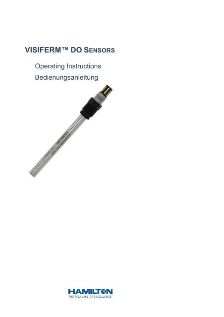
VISIFERM DO SENSORS<br />
Operating Instructions<br />
Bedienungsanleitung
Important note<br />
Copyright © 2008 HAMILTON Bonaduz AG, Bonaduz Switzerland. All rights<br />
reserved. The reproduction of any part of this <strong>do</strong>cument in any form is<br />
forbidden without the express written agreement of HAMILTON Bonaduz AG.<br />
Contents of this manual can be modified without previous announcement.<br />
Technical modifications reserved. Greatest possible care was used on the<br />
correctness of the information in this manual. If errors should be discovered<br />
nevertheless, HAMILTON Bonaduz AG is pleased to be informed about it.<br />
Regardless of this, HAMILTON Bonaduz AG cannot assume a liability for any<br />
errors in this manual or for their consequences.<br />
Wichtiger Hinweis<br />
Copyright © 2008 HAMILTON Bonaduz AG, Bonaduz Schweiz. Alle Rechte<br />
vorbehalten. Die Reproduktion irgendeines Teils dieses Dokuments in jeder<br />
beliebigen Form ist ohne die ausdrückliche schriftliche Zustimmung der<br />
HAMILTON Bonaduz AG untersagt.<br />
Der Inhalt dieses Handbuchs kann ohne vorherige Ankündigung geändert<br />
werden. Technische Änderungen vorbehalten. Es wurde grösstmögliche<br />
Sorgfalt auf die Richtigkeit der Informationen in diesem Handbuch verwendet.<br />
Sollten dennoch Fehler entdeckt werden, würde sich die HAMILTON Bonaduz<br />
AG freuen, darüber informiert zu werden. Ungeachtet dessen kann die<br />
HAMILTON Bonaduz AG keine Haftung für etwaige Fehler in diesem<br />
Handbuch oder deren Folgen übernehmen.
VISIFERM DO Operating Instructions<br />
1. INTRODUCTION................................................................................... ..4<br />
2. INTENDED USE..................................................................................... 4<br />
3. SAFETY INSTRUCTIONS ......................................................................... 5<br />
4. INITIAL OPERATION................................................................................ 5<br />
5. ELECTRICAL CONNECTION...................................................................... 6<br />
ELECTRICAL CONNECTION OF RS-485 MODBUS INTERFACE...................... 7<br />
ELECTRICAL CONNECTION OF 4-20 MA CURRENT INTERFACE.................... 7<br />
EXAMPLES OF SWITCHING...................................................................... 9<br />
ELECTRICAL CONNECTION FOR THE ECS MODE .................................... 11<br />
6. CONFIGURATION OF THE SENSOR......................................................... 12<br />
ACTIVATION OF THE ECS MODE .......................................................... 14<br />
ACTIVATION OF THE 4-20 MA MODE ..................................................... 15<br />
DEFINITION OF THE DESIRED MEASURING VALUE (%, PPM, …) ................. 16<br />
7. PREPARATION FOR THE MEASUREMENT................................................. 17<br />
8. REMOVAL OF THE SENSOR................................................................... 18<br />
9. STERILISATION, AUTOCLAVING, CIP PURIFICATIONS............................... 18<br />
10. TESTING AND MAINTENANCE ................................................................ 19<br />
CALIBRATION ..................................................................................... 19<br />
CALIBRATION IN MODBUS OR 4-20 MA MODE......................................... 19<br />
CALIBRATION IN ECS MODE................................................................ 19<br />
CHANGE OF THE SENSOR CAP ............................................................. 20<br />
11. DISPOSAL.......................................................................................... 21<br />
12. ACCESSORIES .................................................................................... 21<br />
13. TECHNICAL DATA ................................................................................ 23<br />
BEDIENUNGSANLEITUNG DEUTSCH ................................... 25<br />
page 3 of 48
1. Introduction<br />
VISIFERM DO Operating Instructions<br />
Operating Instructions<br />
VISIFERM DO<br />
This manual refers to the optical, sterilizable Hamilton oxygen <strong>sensors</strong><br />
VISIFERM DO.<br />
Designation Order number P/N<br />
VISIFERM DO 120 242 450<br />
VISIFERM DO 160 242 451<br />
VISIFERM DO 225 * 242 452<br />
VISIFERM DO 325 242 453<br />
VISIFERM DO 425 242 454<br />
[* The VISIFERM DO 225 has an actual shaft length of 215 mm in order to<br />
ensure a good rinsing in replaceable armatures such as RETRACTEX!]<br />
Hamilton <strong>sensors</strong> are quality products which are manufactured according to<br />
the latest knowledge. Follow the instructions given here and you can be sure<br />
of maximum safety and durability.<br />
These instructions should be read, understood and followed by all staff using<br />
the device. HAMILTON can assume no responsibility for damage and<br />
operational disruptions arising from failure to observe these instructions.<br />
2. Intended use<br />
VISIFERM DO <strong>sensors</strong> were developed for the measurement of the partial<br />
pressure of solved oxygen as well as the derived measuring variables percent<br />
by volume oxygen, percent air saturation by oxygen and concentration of<br />
oxygen in liquids.<br />
Main application for this sensor is the biotechnology. For it, the sensor exhibits<br />
an unusual long-term stability even at frequent sterilization or autoclaving.<br />
Additionally in other applications such as in the chemical industry, air<br />
surveillance, fish farming as well as water management and sewage<br />
management VISIFERM DO <strong>sensors</strong> already have been proven their value.<br />
In contrast to the electrochemical oxygen <strong>sensors</strong>, VISIFERM DO <strong>sensors</strong><br />
work independently of the installation position. However, at an installation with<br />
the sensor cap perpendicularly <strong>do</strong>wnward, the ascending gas bubbles may<br />
remain at the <strong>sensors</strong> cap silicone layer. These gas bubbles easily may falsify<br />
the measured values or may lead to easily varying measured values.<br />
Beside different interfaces, the VISIFERM DO sensor also contains a<br />
temperature sensor (NTC 22 kΩ). This temperature sensor only has to be<br />
used for the compensation of temperature of the oxygen signal in ECS mode<br />
(simulation of a classical amperometric oxygen sensor by means of<br />
VISIFERM DO). The temperature sensor must not be used for the<br />
regulation of the process temperature.<br />
page 4 of 48
3. Safety instructions<br />
VISIFERM DO Operating Instructions<br />
This sensor only is to be used for the intended use and in an optimum safety<br />
and running conditions. The specifications such as temperature or pressure<br />
being defined in the chapter ‘Technical data’ may not be exceeded under any<br />
circumstances. Threats are imminent if the sensor is not operated correctly or<br />
appropriately.<br />
Assembly and maintenance only have to be performed by trained personnel.<br />
Be careful that the PG 13.5 thread and O-ring are not damaged during the<br />
screwing in into the process. O-rings are wearing parts which regularly have<br />
to be exchanged, at the latest after one year. Even where all necessary safety<br />
measures have been complied with, there are still further risks involving leaks<br />
or mechanical damage to the armature. Where there are seals or screws,<br />
gases or liquids can leak out undetected.<br />
Before removing the sensor make sure that any process medium cannot be<br />
withdrawn.<br />
4. Initial operation<br />
Control the VISIFERM DO sensor during unpacking according to possible<br />
defects. Rejected <strong>sensors</strong> are to be sent to your HAMILTON merchant in the<br />
original packaging.<br />
1 2<br />
3 4<br />
5 6<br />
1: socked head, 2: key areas with serial number, 3: PG 13.5 thread, 4:<br />
O-ring, 5: sensor shaft with fusion number of the stainless steel, 6, 7:<br />
sensor cap with oxygen sensitive silicone luminophore (sensory element),<br />
serial number of the sensor cap and fusion number of the stainless steel.<br />
VISIFERM DO <strong>sensors</strong> are delivered by the factory according to the<br />
operation with the integrated 4-20mA power interface as well as to the always<br />
active serial RS-485 bus interface (Modbus RTU – protocol). You also find this<br />
information on the provided certificate which also contains the serial number<br />
as well as the most important specifications.<br />
ATTENTION !<br />
For the operation at measuring amplifiers which are designed for<br />
classical amperometric <strong>sensors</strong> (Clark cells) a software<br />
configuration in the ECS mode (electrochemical sensor) is needed!<br />
page 5 of 48<br />
7
ATTENTION !<br />
VISIFERM DO Operating Instructions<br />
In the ECS mode the sensor can be demolished if you try to operate<br />
the sensor as a 4-20 mA sensor!<br />
ATTENTION !<br />
For the avoidance of humidity problems the sensor cap has to be<br />
screwed on the sensor shaft firmly. Furthermore, the O-ring between<br />
the shaft and cap has to be undamaged!<br />
Avoid electrical damages at the sensor! Follow the instructions in the chapters<br />
‘Electrical Connection’ and ‘Configuration of the sensor’ in order to adjust the<br />
sensor to your application and desires!<br />
Before the assignment of the sensor for measurement, control or regulation<br />
you should examine the sensor configuration by means of an operational test.<br />
5. Electrical connection<br />
VISIFERM DO <strong>sensors</strong> are fitted with a VP 8.0<br />
socket head. The eight golden contacts are<br />
denoted as pin A, pin B, ..., and pin H. For an<br />
easy assignment of the pins the socket head has<br />
a codification between pin A and pin B.<br />
For connecting VISIFERM DO <strong>sensors</strong> most easily and safe use<br />
HAMILTON VP 8.0 cables which are available in different lengths!<br />
VP pin Function<br />
A cathode (only in ECS mode)<br />
B - 4-20 mA mode: 4-20 mA current sink. Works as entrance<br />
for current which flows to the mass in an internally regulated<br />
manner.<br />
- ECS mode: anode. Never connect in the ECS mode with<br />
+2 V or more!<br />
C Power supply: +24 VDC (7…30 VDC),<br />
Start-up power 1 W, continuous power 0,6 W<br />
D Power supply: ground<br />
E Temperature sensor NTC 22k for ECS mode<br />
F Temperature sensor NTC 22k for ECS mode<br />
G RS-485 (A)<br />
H RS-485 (B)<br />
casing Sensor shaft (for shielding). The outside shielding of the VP<br />
cable preferably should be connected to power supply<br />
ground (Pin D). In rare cases it is advantageous to connect<br />
the shielding with the protective earth instead with the<br />
ground.<br />
page 6 of 48<br />
A<br />
B C D<br />
G F<br />
E<br />
H
VISIFERM DO Operating Instructions<br />
Electrical connection of the RS-485 Modbus interface<br />
By means of the correct password the sensor can be adapted to many<br />
parameters such as:<br />
Switching of 4-20 mA into ECS mode,<br />
Scaling of the 4-20 mA interface,<br />
Adjustment of the ECS characteristic values (zero current and air<br />
current, TK),<br />
Definition of the measured value: % oxygen air saturation (% sat), vol.-<br />
%, mg/l, ppb,<br />
Salinity of the measuring solution for calculation of the concentration<br />
values (mg/l).<br />
Additionally sensor information can be read back from the RS-485 interface<br />
such as:<br />
Serial number, order number (P/N) and manufacturing number (WO),<br />
Firmware version,<br />
Status (consumption of the sensor cap, operation hours, number of<br />
CIP cycles and sterilisations, warnings, mistakes, …).<br />
You can find information about the use of the interface RS-485 in the section<br />
‘Configuration of the sensor‘!<br />
Additional information:<br />
Physically, the RS 485 Modbus interface is a serial standard interface RS-485<br />
in 2-wire-operation. In this case a command (for example ‘send the measured<br />
value’) is sent from a master (Host, PC or SPS) to a slave (Client,<br />
VISIFERM DO) via two wires (RS-485 wire A (VP 8.0 Pin G) and RS-485<br />
conductor B (VP 8.0 Pin H)) in half-duplex. Thereupon the addressed slave<br />
answers with the required information in a temporary shift.<br />
The used Modbus RTU communication protocol corresponds to the standard<br />
Modbus IDA, see also http://www.modbus.org. VISIFERM DO uses an open<br />
register set developed by HAMILTON. Additional information about the<br />
register content and instruction structure may be found at<br />
http://www.pHeasy.com/dnld/software.<br />
Electrical connection of the 4-20 mA current interface<br />
The 4-20 mA mode enables a direct connection of the VISIFERM DO<br />
sensor at a data recorder, indicator, control unit, SPS or process control<br />
system. Besides the two conducting wires for the previously temperature<br />
compensated 4-20 mA oxygen signal and a suitable, galvanically separated<br />
analogue input only an additional power supply of the VISIFERM DO sensor<br />
is necessary (VP 8.0 pins C and D, vide infra).<br />
VISIFERM DO <strong>sensors</strong> are delivered in 4-20 mA mode by the factory (see<br />
certificate of the sensor).<br />
ATTENTION !<br />
Ensure that the sensor is adjusted at the 4-20 mA mode! If the sensor<br />
is configured in the ECS mode, and if you use it as a 4-20 mA sensor,<br />
then this operation can result in irreparable damages in the sensor!<br />
See also the chapter ‘Configuration of the sensor‘/ ‘Activation of the<br />
4-20 mA mode‘!<br />
page 7 of 48
ATTENTION !<br />
VISIFERM DO Operating Instructions<br />
In the ECS mode an enhanced voltage (greater than 2 VDC) at pin B<br />
may result to a damage of the sensor! Note: Only in the 4-20 mA mode<br />
an enhanced voltage (max. 24 VDC) for the running of the current<br />
interface may be applied to pin B!<br />
In the 4-20 mA mode the following pin occupancy with the allocation of the VP<br />
cable conductor colors are presented in the table:<br />
VISIFERM DO VP pin VP 6.0 single<br />
coaxial cable<br />
has not to be<br />
connected!<br />
4-20 mA drain (current<br />
entrance; The current<br />
intensity (mA) flowing<br />
in the sensor to the<br />
mass is controlled in<br />
the sensor)!<br />
power supply: +24<br />
VDC (7…30 VDC),<br />
max. 1000 mW<br />
A coaxial core<br />
black<br />
transparent<br />
B coaxial shield<br />
black<br />
page 8 of 48<br />
VP 8.0 <strong>do</strong>uble<br />
coaxial cable<br />
coaxial core<br />
black<br />
transparent<br />
coaxial shield<br />
black<br />
C grey coaxial core<br />
red transparent<br />
power supply: ground D blue coaxial shield<br />
red transparent<br />
NTC 22 kΩ (is not<br />
used in 4-20 mA mode)<br />
E white White<br />
NTC 22 kΩ (is not<br />
used in 4-20 mA mode)<br />
F green Green<br />
RS-485 (A) G --- Yellow<br />
RS-485 (B) H --- Brown<br />
sensor shaft (connect<br />
with the ground of the<br />
power supply)<br />
ATTENTION !<br />
shield cable shield:<br />
green-yellow<br />
cable shield:<br />
green-yellow<br />
The sensor has a regulated 4-20 mA current drain! No current source!<br />
Only the current from a SPS or something like that can be measured<br />
which flows from e.g. +24VDC into the sensor! Therefore the analogue<br />
input of the SPS may not be galvanically connected with the ground of<br />
the sensor (see the following illustrations for switching examples)<br />
ATTENTION !<br />
The 4...20mA interface only may be operated if the power supply of the<br />
sensor is guaranteed!<br />
Particularly in EMV loaded environment it is advisable to put the sensor shaft<br />
and/or VP cable shield on ground or earth. This clearly improves the noise<br />
immunity and signal quality!<br />
The 4...20mA interface is configured by the factory with the measuring range<br />
and the measured value / unit indicated in the certificate. Follow the<br />
instructions in the chapter ‘Configuration of the sensor‘ according to the
VISIFERM DO Operating Instructions<br />
adjustment to your application! There you also may find hints according to the<br />
examination of the 4-20 mA current loop with adjustable test currents (fixed<br />
test value).<br />
Examples of circuit arrangement<br />
sensor<br />
+ 24 VDC<br />
VP pin C<br />
VP pin B<br />
4-20mA<br />
control<br />
0 VDC; ground<br />
VP pin D<br />
Fig. A: General view of wiring for the 4-20 mA mode. The sensor works as<br />
a current sink. The current flowing to the ground in the sensor is<br />
measured.<br />
sensor<br />
+ 24 VDC<br />
VP pin C<br />
VP pin B<br />
4-20mA<br />
control<br />
0 VDC; ground<br />
VP pin D<br />
4-20mA<br />
4-20mA<br />
Measurement<br />
against the ground<br />
cannot be operated!<br />
4-20mA<br />
Fig. B: The sensor has no current source with which the current flowing to<br />
the ground outside of the sensor can be measured!<br />
page 9 of 48<br />
PLC<br />
+ 24 VDC<br />
power<br />
supply<br />
0 VDC; ground<br />
+ 24 VDC<br />
power supply<br />
PLC<br />
0 VDC; ground
sensor<br />
+ 24 VDC<br />
VP pin C<br />
VP pin B<br />
4-20mA<br />
control<br />
0 VDC; ground<br />
VP pin D<br />
VISIFERM DO Operating Instructions<br />
4-20 mA<br />
-<br />
Fig. C: The safest form of wiring: Wire an isolation amplifier as shown<br />
above, e.g. the HAMILTON 4-20mA Galvanic Isolator M1, part<br />
number P/N 242412.<br />
sensor<br />
Fig. D: This simple wiring with common power supply only is possible, if<br />
the analog input of the PLC is galvanically separated from the<br />
ground!<br />
sensor<br />
+ 24 VDC<br />
VP pin C<br />
VP pin B<br />
4-20mA<br />
control<br />
0 VDC; ground<br />
VP pin D<br />
+12 VDC<br />
VP pin C<br />
VP pin B<br />
4-20mA<br />
control<br />
+<br />
input<br />
output<br />
0 VDC; ground<br />
VP pin D<br />
separate<br />
power supply<br />
Abb. E: If two electrically (galvanic) isolated power supplies are used, also<br />
the above shown connecting scheme is possible!<br />
page 10 of 48<br />
4-20 mA<br />
4-20 mA<br />
4-20 mA<br />
+<br />
+<br />
-<br />
+ 24 VDC<br />
PLC<br />
+ 24 VDC<br />
analog<br />
input<br />
U<br />
0 VDC; ground<br />
PLC<br />
- Galvanic<br />
isolated analog<br />
input<br />
0 VDC; ground<br />
analog<br />
input<br />
PLC
VISIFERM DO Operating Instructions<br />
Electrical connection for the ECS mode<br />
The ECS mode enables the simulation of an electrochemical sensor. Thus a<br />
VISIFERM DO sensor can be connected to classical measuring devices<br />
instead of amperometric oxygen <strong>sensors</strong> (Clark cells). Furthermore only the<br />
power supply of the VISIFERM DO sensor is necessary (VP 8.0 pins C and<br />
D, vide infra). Put the ECS mode into operation as described in the chapter<br />
‚Configuration of the sensor‘ / ‚Activation of the ECS mode‘!<br />
ATTENTION !<br />
Apply any high voltage (max. 2 VDC) at pin B (anode)! This can result<br />
in a destruction of the sensor in ECS mode! Note: Only in 4-20 mA<br />
mode a high voltage (max. 24 VDC) may be applied in order to operate<br />
the current interface!<br />
ATTENTION !<br />
Since the <strong>sensors</strong> are supplied in 4-20 mA mode by the factory the<br />
sensor initially has to be configured for the ECS mode (see chapter<br />
‘Configuration of the sensor‘)!<br />
In the ECS mode the following pin occupancy with the allocation of the VP<br />
cable conductor colors are presented in the table:<br />
VISIFERM DO VP pin VP 6.0 single<br />
coaxial cable<br />
cathode A coaxial core<br />
black<br />
transparent<br />
anode<br />
ATTENTION: In ECS<br />
mode never connect<br />
with e.g. 24 V!<br />
power supply: +24<br />
VDC (7…30 VDC),<br />
max. 1000 mW<br />
B coaxial shield<br />
black<br />
page 11 of 48<br />
VP 8.0 <strong>do</strong>uble<br />
coaxial cable<br />
coaxial core<br />
black<br />
transparent<br />
coaxial shield<br />
black<br />
C Grey coaxial core<br />
red transparent<br />
power supply: ground D Blue coaxial shield<br />
red<br />
NTC 22 kΩ E White White<br />
NTC 22 kΩ F Green Green<br />
RS-485 (A) G --- Yellow<br />
RS-485 (B) H --- Brown<br />
sensor shaft (connect<br />
with the mass of the<br />
power supply)<br />
shield cable shield:<br />
green-yellow<br />
cable shield:<br />
green-yellow<br />
Particularly in EMV loaded environment it is advisable to put the sensor shaft<br />
and/or VP cable shield on ground or earth. This clearly improves the noise<br />
immunity and signal quality!<br />
The NTC temperature sensor attached to the pins E and F is isolated from the<br />
remainder of the integrated electronics and is used for the temperature<br />
compensation of the oxygen signal in the measuring device. If the measuring<br />
device is not designed for typical sterilizable oxygen <strong>sensors</strong>, then the<br />
measuring device probably expects another type of temperature sensor.<br />
Therefore the measuring device neither can compensate the temperature
VISIFERM DO Operating Instructions<br />
depending oxygen signal nor display the temperature correctly. If the<br />
temperature at the measuring device is displayed correctly, then the<br />
measuring device and temperature sensor of VISIFERM DO probably are<br />
compatible!<br />
Usually classical <strong>sensors</strong> are operated with a polarization voltage between<br />
anode and cathode. This polarization voltage is supplied by the measuring<br />
device. VISIFERM DO can be operated with polarization voltages usual for<br />
electrochemical <strong>sensors</strong>. The sensor is optimized for a polarization voltage of<br />
-675mV.<br />
For adjustment to different measuring devices and/or for simulation of different<br />
amperometric <strong>sensors</strong> the current can be adjusted in air by means of the<br />
VisiConfigurator between 0...500 nA (see chapter ‘Configuration of the sensor‘,<br />
section ‘Activation of the ECS mode‘).<br />
6. Configuration of the sensor<br />
In order to configurate the sensor according to your requirements you proceed<br />
as follows:<br />
1. Installation of HAMILTON USB-RS-485 Modbus converter (P/N:<br />
242411) with the driver software (freeware and installation guidance<br />
available under http://www.pHeasy.com/dnld/software) on a personal<br />
computer or notebook. Attention: Please, only use the Hamilton RS-<br />
485 converter specified above, because only few RS-485 converters<br />
available in the commerce also actually are Modbus suitable!<br />
VISIFERM DO uses the RS-485 in 2-conductor-operation.<br />
2. Installation of HAMILTON Freeware ‘VisiConfigurator‘ (available<br />
under http://www.pHeasy.com/dnld/software) for a simple<br />
configuration of the sensor and communication on the personal<br />
computer or notebook.<br />
3. Utilization of VISIFERM DO demo cable (P/N: 355194, already<br />
contains a plug power pack), in order to a) supply the sensor with<br />
energy, and b) connect the two RS-485 conducting wires (yellow and<br />
brown) at USB-RS-485. If you use a standard VP 8.0 cable, then<br />
additionally you have to supply the sensor with voltage (pin C:<br />
24VDC; pin D: 0 VDC).<br />
4. Start the VisiConfigurator and select the com-port of the RS-485<br />
converter in the menu interface. The baud rate may be found on the<br />
certificate of the sensor. However it must not be changed. The<br />
standard value is 19.200 bd.<br />
5. In order to send an instruction to the sensor click on the button ‘Go’.<br />
If you click on ‘Go’ in the program area ‘Measurement’, then the<br />
page 12 of 48
VISIFERM DO Operating Instructions<br />
measuring values should appear on the right side.<br />
HINT: Go with the pointer of the mouse over the field description in<br />
the VisiConfigurator in order to get additional references and<br />
assistance according to the respective field.<br />
6. By means of a suitable program area the most important<br />
configuration data can be read out (user) or altered (specialist) in<br />
dependence of the user status (user levels: U = user, A =<br />
administrator, S = specialist). The administrator can accomplish<br />
calibrations, but change no other parameters.<br />
7. Alter the user status in the program area ‘User Level‘ with ‘Change<br />
User Level‘ by inputs according to the subsequent schedule.<br />
User status User<br />
Level<br />
Password till<br />
firmware<br />
Modbus 29<br />
page 13 of 48<br />
Password from<br />
Modbus<br />
firmware 30<br />
user U 0 0<br />
administrator A 12345 18111978<br />
specialist S 123456 16021966<br />
In order to find out the version of the firmware go to: Sensor Info /<br />
Command: Read sensor info / Go. The version of the firmware as<br />
well as further information appear (vide infra).
Activation of the ECS mode<br />
VISIFERM DO Operating Instructions<br />
Configure the sensor with VisiConfigurator as follows:<br />
1. User Level / Command: Change user level / New user level: S /<br />
Password: see table above / Go. Now a ‘S’ must appear on the right<br />
side in the field: ‘New user level’. Thus you have the user rights of a<br />
specialist and you can reconfigure the sensor!<br />
2. Configuration Interface / Command: Write current interface mode /<br />
Interface: 512 / Go. Now a ‘512’ must appear on the right side in the<br />
field ‘Interface’. Thus you have deactivated the 4-20 mA interface<br />
and activated the ECS. Now the ECS interface has to be adjusted!<br />
3. Configuration Interface / Command: Write configuration ECS<br />
interface / Current in zero oxygen (+25°C): 0 / Current in air (+25°C):<br />
60 / Temperature coefficient: 3.1 / Fixed test value: 80 / Go. Now the<br />
same values have to appear on the right side. Thus you have<br />
page 14 of 48
VISIFERM DO Operating Instructions<br />
configured the ECS interface completely. The above values<br />
correspond to a typical OXYFERM oxygen sensor with 60 nA at air<br />
and at a temperature of 25°C.<br />
HINT: If you input ‘256’ instead of ‘512’ in the 2nd step, then the current<br />
corresponding to the value in the field ‘Fixed test value’ is supplied over the<br />
ECS interface! This would be 80 nA in our example. This test mode is helpful<br />
in order to test the ECS interface, the cable and the oxygen measuring device!<br />
Activation of the 4-20 mA mode<br />
Configure the sensor with VisiConfigurator as follows:<br />
1. At first, it is essential to adjust the right measuring value (vide infra)!<br />
In the following we assume that you have decided for the<br />
measurement in %-oxygen air saturation (%-sat). The adjustments<br />
for the other measured values take place in a similar way.<br />
2. If you are not yet on the specialist level already: User Level /<br />
Command: Change user level / New user level: S / Password: see<br />
table above / Go. Now a ‘S’ has to appear on the right side in the<br />
field ‘New user level’. Thus you have the user rights of a specialist<br />
and may reconfigure the sensor!<br />
3. Configuration Interface / Command: Write current interface mode /<br />
Interface: 2 / Go. Now a ‘2’ has to appear on the right side of the field<br />
‘Interface’. Thus you have deactivated the ECS interface and<br />
activated the 4-20 mA interface. Now the 4-20 mA interface has to be<br />
adjusted!<br />
4. As an example, 4 mA 0% and 20 mA 160% oxygen air saturation<br />
shall be assigned. Configuration Interface / Command: Write<br />
configuration 4…20 mA interface / Oxygen value at 4mA: 0 / Oxygen<br />
value at 20mA: 160 / Fixed test value: 10 / Go. Now the same values<br />
have to appear again on the right side. Furthermore, the measuring<br />
unit is displayed for control. Thus you have configured the 4-20 mA<br />
interface completely.<br />
page 15 of 48
VISIFERM DO Operating Instructions<br />
HINT: If you enter a ‘1’ instead of ‘2’ in the 3rd step, then the current<br />
corresponding to the value in the field ‘Fixed test value’ is supplied over the 4-<br />
20 mA interface! This would be 10 mA in our example. This test mode is<br />
helpful in order to test the current interface and the processing of measured<br />
variables in the process control system or on a 20 mA display!<br />
Definition of the desired measuring value (%, ppm, …)<br />
Configure the sensor with VisiConfigurator as follows:<br />
1. If you are not yet on the specialist level already: User Level /<br />
Command: Change user level / New user level: S / Password: see<br />
table above / Go. Now a ‘S’ has to appear on the right side in the<br />
field ‘New user level’. Thus you have the user rights of a specialist<br />
and may reconfigure the sensor!<br />
2. Configuration Measurement / Command: Write units of measurement<br />
/ Oxygen value: click and select / Temperature value: click and select<br />
/ Go. Now the same values have to appear on the right side. Thus<br />
you have adjusted the measuring values!<br />
page 16 of 48
ATTENTION !<br />
VISIFERM DO Operating Instructions<br />
When using the sensor in the 4-20 mA mode, the 4-20 mA interface<br />
must become configured again! See also, ‘Activation of the 4-20 mA<br />
mode’.<br />
3. If you should have selected a concentration (mg/L, ppm, ug/L or ppb)<br />
as a measuring value, then you may input the salinity in mS/cm for<br />
the correct calculation of the concentration of salty measuring media<br />
such as waste water: Configuration measurement / Set salinity of<br />
process water / Salinity: …. / Go.<br />
7. Preparation for the measurement<br />
1. Removal of possibly present protective caps from the VP head and<br />
from the sensor cap.<br />
2. Ensuring that the sensor was configured per software as desired. In<br />
the case of <strong>do</strong>ubt, definitely examine as described in the section<br />
‘Electrical connection: RS-485 Modbus interface’! At this stage also<br />
the state of the sensor and sensor cap can be checked in the<br />
VisiConfigurator program area ‘Sensor Info’.<br />
3. Installation of the sensor (thread: PG 13.5).<br />
4. Attach the VISIFERM DO sensor according to chapter ‘Electrical<br />
Connection‘ in the desired configuration. Note: Due to the integrated<br />
optoelectronics the sensor has an intrinsic warming which stabilizes<br />
itself within few minutes. If the sensor is not dipped into the liquid,<br />
then it displays a mildly enhanced temperature.<br />
5. If the sensor is operated in the ECS mode, then the used measuring<br />
device must be calibrated (adjusted) according to the sensor. For this,<br />
follow the instructions of the manufacturer of the measuring devices.<br />
page 17 of 48
VISIFERM DO Operating Instructions<br />
If the sensor is operated in the 4-20 mA mode or purely digitally by<br />
means of RS-485, then the calibration can be performed via RS-485<br />
by means of a personal computer or VISICAL (P/N: 242410) – if<br />
necessarily at all. The calibration preferably is performed in vaporsaturated<br />
interior atmosphere. Calibration in normal interior<br />
atmosphere results into a small measurement error of nearly 2% of<br />
the measuring value.<br />
6. The sensor now is ready for measurement.<br />
ATTENTION !<br />
For the avoidance of humidity problems the sensor cap has to be firmly<br />
screwed on the sensor shaft. Furthermore, the O-ring between the<br />
shaft and cap has to be present!<br />
8. Removal of the sensor<br />
Before removing the sensor, make sure that no process medium can be<br />
withdrawn thereby.<br />
Separate the PG 13.5 thread and pull out the sensor. Do not turn the sensor<br />
at the socket head because otherwise the sensor cap loosens itself, and<br />
humidity reaches the interior of the sensor!<br />
9. Sterilization, autoclaving, CIP purifications<br />
VISIFERM DO <strong>sensors</strong> are laid out in order to exist harmless in cleaning<br />
procedures usually used in biotechnology without special precautions.<br />
Nevertheless it has been shown in practice as expected that a frequent<br />
cleaning with steam or hot caustic solutions lead to a shortened life span of<br />
the sensor cap. Quantitative statements are not possible since in particular<br />
with CIP purifications it depends on a detailed composition as well as on the<br />
temperature gradient. With steam sterilizations and autoclaving for a time<br />
period of thirty minutes at a temperature of 125°C one may proceed from a<br />
typical life span of more than 50 cycles per exchangeable sensor cap.<br />
The contacts must be clean and dry before the sensor is connected to the<br />
cable.<br />
ATTENTION !<br />
The sensor is able to communicate at a temperature of 80°C (on<br />
request also at higher temperatures). However no measurement of<br />
oxygen is performed in order to take care of the optoelectronics and<br />
luminophore. The last measured value before exceeding the<br />
temperature is frozen and exists again when falling below the<br />
temperature limit. Therefore, starting from this temperature the sensor<br />
cannot be used for control, regulation and monitoring.<br />
NOTE !<br />
The sensor has an easily shifted zero point (max. 1% of the measuring<br />
value, 80 ppb) at the end of the temperature cycle of more than 50°C.<br />
Usually this only plays a role in the measurement of traces of oxygen.<br />
page 18 of 48
VISIFERM DO Operating Instructions<br />
10. Testing and maintenance<br />
Calibration<br />
According to the standards, the sensor can be calibrated at air or in oxygenfree<br />
environment (zero point). This is very rarely necessary in the most<br />
applications. If there are already displacements of measuring values of only<br />
few percents within few days, then a damage of the luminophore due to<br />
measuring medium and cleaning medium has to be expected. In this case it<br />
has to be considered whether a more frequent exchange of the sensor cap<br />
can be accepted or whether another measuring principle e.g. with a classical<br />
OXYFERM sensor should be used!<br />
HINT: The sensor needs a preheating time of 10-15 minutes after switching<br />
on. In this phase measurements are already possible. However, for an optimal<br />
calibration you should wait this time.<br />
Calibration in Modbus or 4-20 mA mode<br />
The calibration of the sensor in the 4-20 mA mode only is possible via Modbus<br />
RTU. Therefore, most easily VISICAL or the VisiConfigurator freeware with<br />
the USB-RS-485 Modbus converter can be used (see chapter ‘Configuration<br />
of the <strong>sensors</strong>‘ and ‘Accessories‘). The operation of the accessories is shown<br />
by the specific instructions.<br />
During the calibration the sensor independently examines the correctness and<br />
stability of the oxygen signal.<br />
Calibration in ECS mode<br />
The calibration in ECS mode takes place like in classical <strong>sensors</strong> in the<br />
measuring device at which the sensor is connected. For this, consult the<br />
operation instructions of the measuring device!<br />
HINT: The concept of VISIFERM DO <strong>sensors</strong> enables the calibration of all<br />
used <strong>sensors</strong> in the lab with a VISICAL module or with a personal computer or<br />
laptop via Modbus and then a direct use at classical measuring devices<br />
without a new calibration at the measuring device. This is possible, since with<br />
page 19 of 48
VISIFERM DO Operating Instructions<br />
the calibration with the VISICAL module or Modbus also the ECS interface is<br />
calibrated. Thus, if in the configuration of the ECS interface a ‘Current in Air’ –<br />
an air current of 60 nA – was adjusted and the measuring device once was<br />
calibrated with the VISICAL module or Modbus, then the measuring device<br />
has set the air current at 25°C on 60 nA. Since all freshly calibrated <strong>sensors</strong><br />
deliver the same values (60nA at air), a recalibration of the measuring device<br />
is not necessary!<br />
Change of the sensor cap<br />
Three-part sensor caps<br />
Until nearly May 2008 three-part sensor caps are delivered.<br />
The exchange of these caps is performed as<br />
3<br />
described below for the one-part sensor caps.<br />
However, you have to pay attention to the correct<br />
2<br />
fitting of the sealing rings (2) between the steel<br />
1<br />
sleeve (1) and glass support (3). The black area<br />
of the glass support has to show outward to the measuring substance. Install<br />
these sensor caps carefully in order to guarantee the right position and correct<br />
sealing effect of the very thin sealing ring! ATTENTION: Without correctly<br />
positioned sealing ring the interior of the sensor is filled with a liquid. By this<br />
the sensor is damaged irreparably!<br />
One-part sensor caps<br />
Starting from approximately May 2008, only one-part sensor caps with a<br />
simplified and safe handling are delivered. The change between these sensor<br />
caps is performed very easily:<br />
O-ring<br />
/<br />
unscrew<br />
Unscrew the old sensor caps (normal nuts against the clockwise direction)<br />
from the shaft. HINT: If the sensor cap is mounted very firmly on the shaft,<br />
and if you <strong>do</strong> not find any stop on the stainless steel with the fingers, then a<br />
silicone tube between finger and metal may supply a good grip.<br />
Examine the small O-ring which seals the sensor cap against the sensor shaft.<br />
Exchange this O-ring, if traces of utility are seen at the O-ring. One O-ring as<br />
a substitute is contained in the supply of substitute sensor caps.<br />
Screw the new sensor cap again on the sensor shaft. Make sure that the gap<br />
between the shaft and cap is closed, and therefore that the sealing effect of<br />
the O-ring under it is guaranteed. In order to fulfill the traceability (FDA) note<br />
the serial number of the new sensor cap.<br />
Examine the measuring values of the sensor at air and, if necessary, in an<br />
oxygen-free medium. If the measuring values should deviate too much, then<br />
repeat the calibration.<br />
page 20 of 48
11. Disposal<br />
VISIFERM DO Operating Instructions<br />
The design of HAMILTON <strong>sensors</strong> optimally considers<br />
environmentally compatibility. In accordance with the EC guideline<br />
2002/96/EG HAMILTON <strong>sensors</strong> have to be supplied to a separated<br />
collection for electrical and electronic devices or may be send to<br />
HAMILTON for disposal. They may not be supplied to the unsorted settlement<br />
waste.<br />
12. Accessories<br />
VISIFERM DO with unscrewed sensor cap<br />
VISICAL<br />
USB-RS-485 Modbus Converter<br />
VISIFERM – D4 Power Adapter: for the connection of VISIFERM DO in<br />
ECS mode at the cable of classical sterilizable oxygen sensor with four-pole<br />
plug (D4, T82). Includes a wall plug power supply.<br />
Sensor Cable VP 8.0<br />
page 21 of 48
Order number Description<br />
VISIFERM DO Operating Instructions<br />
242450 VISIFERM DO 120<br />
242451 VISIFERM DO 160<br />
242452 VISIFERM DO 225<br />
242453 VISIFERM DO 325<br />
242454 VISIFERM DO 425<br />
242427 VISIFERM DO sensor cap<br />
242410 VISICAL<br />
242411 USB-RS-485 Modbus converter<br />
242412 4-20 mA galvanic isolating amplifier M1<br />
242413 VISIFERM-D4 Power Adapter<br />
355194 VISIFERM demo cable<br />
(1m, open end, with plug power pack)<br />
238999-2766 VISIFERM demo cable (1m, for Sartorius-BBI<br />
fermenter, with plug power pack)<br />
238999-2767 VISIFERM demo cable (1m, e.g. for Applikon<br />
fermenter, with BNC plug and plug power pack)<br />
238999-2768 VISIFERM demo cable (1m, for New Brunswick<br />
fermenter, with plug power pack)<br />
238999-2394 sensor cable VP 8.0, 1m<br />
238999-1953 sensor cable VP 8.0, 3m<br />
238999-2395 sensor cable VP 8.0, 5m<br />
238999-2396 sensor cable VP 8.0, 10m<br />
238999-2403 sensor cable VP 8.0, 15m<br />
238999-2505 sensor cable VP 8.0, 20m<br />
page 22 of 48
13. Technical data<br />
VISIFERM DO Operating Instructions<br />
Optical oxygen sensor with integrated optoelectronic, functionality of<br />
measuring devices and self-diagnosis<br />
Steam sterilizable, autoclavable and CIP suited (tested with 1.0M<br />
NaOH, 90°C)<br />
Measurement principle: oxygen dependent change of phase angle of a<br />
silicone protected luminophore<br />
Sensor works without a mechanically sensitive membrane and without<br />
a corrosive electrolyte<br />
No minimum flow required, since the sensor <strong>do</strong>es not consume oxygen<br />
The sensor immediately is ready for measurement and <strong>do</strong>es not need<br />
any polarization time. For thermal reasons (self-heating) nearly 5-10<br />
min. are necessary for very stable measured values after starting the<br />
power supply.<br />
Shaft with a diameter of 12 mm and PG 13.5 thread<br />
Different lengths of shaft, from 120 mm<br />
Exchangeable sensor caps<br />
Storage temperature: -10 … 50°C<br />
Operation temperature: -10 … 130°C; Disconnection of the optical<br />
oxygen measuring function above 80°C; electrical interfaces and<br />
temperature measurement up to 130°C active.<br />
Process pressure: -1 … 12 bar / 174 psi; pressure impulses up to 80<br />
bar<br />
Range of measurement: 4 ppb/0.05% … 300% oxygen – air saturation;<br />
Measured value can be configured by software according to:<br />
% oxygen air saturation (%-sat)<br />
Volume-% oxygen (Vol-%)<br />
mg/L or ppm<br />
ug/L or ppb<br />
Response time at 25°C, from air to nitrogen; t98% < 30 s<br />
Detection limit: 0.01 Vol-%<br />
Drift: lower than 0.2 Vol-% oxygen per week in air at 30°C and<br />
constant conditions<br />
Medium affected materials: see certificate<br />
Different modi of operation are adjustable by means of the software,<br />
e.g.:<br />
4-20 mA interface, or alternatively<br />
ECS interface<br />
Device address and transmission rate for the operation at a<br />
Modbus RTU fieldbus, so that several <strong>sensors</strong> can be read out<br />
by means of the same two conductors of the RS-485 interface<br />
of a process control system or a personal system.<br />
Electrical connection: VP 8.0 socket head:<br />
7 … 30 VDC operating voltage; max. 1000 mW<br />
page 23 of 48
Modbus:<br />
VISIFERM DO Operating Instructions<br />
Continuous power approx. 0.6 W<br />
Start-up power max. 1 W (since Firmware ‘Modbus_031’)<br />
Freely scalable 4-20 mA current interface (current sink) for a<br />
temperature compensated oxygen measuring signal. Is fed from<br />
outside with e.g. 24 VDC, whereby the current coming into the<br />
sensor can be measured by a 4-20 mA display of a measuring<br />
data recorder. In the sensor the current flows against the mass<br />
of the operating voltage.<br />
ECS interface for the simulation of a classical, electrochemical<br />
sensor (cathode, anode, NTC 22 kOhm temperature sensor) for<br />
the operation at classical measuring devices<br />
Fieldbus interface: digital serial RS-485 interface with Modbus<br />
RTU protocol<br />
Modbus RTU wire<br />
2-conductor RS-485<br />
maximal 32 addresses<br />
Transmission rate / baud rate:<br />
4800 bis 115000 bd.; factory standard: 19200 bd.<br />
Cross sensitivities and resistances:<br />
Not disturbing are: CO2, H2S, SO2, ethylene oxide or gammasterilization<br />
Resistant towards ethanol, methanol, H2O2<br />
Non resistant towards chlorine gas and other organic solvents<br />
such as chloroform, toluene, acetone<br />
page 24 of 48
VISIFERM DO Operating Instructions<br />
Bedienungsanleitung<br />
VISIFERM DO<br />
page 25 of 48
Operating Instructions VISIFERM DO<br />
1. EINLEITUNG 27<br />
2. BESTIMMUNGSGEMÄSSE VERWENDUNG 27<br />
3. SICHERHEITSHINWEISE 28<br />
4. ERSTE INBETRIEBNAHME 28<br />
5. ELEKTRISCHER ANSCHLUSS 29<br />
ELEKTRISCHER ANSCHLUSS DER RS-485 MODBUS SCHNITTSTELLE 30<br />
ELEKTRISCHER ANSCHLUSS DER 4-20 MA STROM-SCHNITTSTELLE 30<br />
SCHALTUNGSBEISPIELE 32<br />
ELEKTRISCHER ANSCHLUSS FÜR DEN ECS-MODUS 34<br />
6. KONFIGURATION DES SENSORS 35<br />
DEN ECS-MODUS AKTIVIEREN 37<br />
DEN 4-20 MA-MODUS AKTIVIEREN 38<br />
DIE GEWÜNSCHTE MESSGRÖSSE (%, PPM, …) DEFINIEREN 39<br />
7. VORBEREITUNG ZUR MESSUNG 40<br />
8. AUSBAU DES SENSORS 41<br />
9. STERILISATION, AUTOKLAVIERUNG, CIP-REINIGUNGEN 41<br />
10. TEST UND WARTUNG 42<br />
KALIBRATION 42<br />
KALIBRATION IM MODBUS ODER 4-20 MA-MODUS 42<br />
KALIBRATION IM ECS-MODUS 43<br />
WECHSEL DER SENSORKAPPE 43<br />
11. ENTSORGUNG 44<br />
12. ZUBEHÖR 44<br />
13. TECHNISCHE DATEN 46<br />
Page 26 of 48
1. Einleitung<br />
Operating Instructions VISIFERM DO<br />
Bedienungsanleitung<br />
VISIFERM DO<br />
Diese Betriebsanleitung bezieht sich auf die optischen, sterilisierbaren<br />
Hamilton Sauerstoff-Sensoren VISIFERM DO.<br />
Bezeichnung Bestellnummer P/N<br />
VISIFERM DO 120 242 450<br />
VISIFERM DO 160 242 451<br />
VISIFERM DO 225 * 242 452<br />
VISIFERM DO 325 242 453<br />
VISIFERM DO 425 242 454<br />
[* Die VISIFERM DO 225 hat eine tatsächliche Schaftlänge von 215 mm,<br />
um eine gute Umspülung in Wechselarmaturen wie beispielsweise<br />
RETRACTEX zu gewährleisten!]<br />
Hamilton Sensoren sind nach neuesten Erkenntnissen hergestellte<br />
Qualitätsprodukte. Nur bei genauer Beachtung der nachstehenden<br />
Hinweise erreichen Sie ein Höchstmass an Genauigkeit und eine<br />
maximale Lebensdauer.<br />
Diese Betriebsanleitung muss vom zuständigen Personal gelesen,<br />
verstanden und beachtet werden. Für Schäden und Betriebsstörungen,<br />
die sich aus Nichtbeachten der Betriebsanleitung ergeben, übernimmt die<br />
Firma HAMILTON keine Haftung.<br />
2. Bestimmungsgemässe Verwendung<br />
VISIFERM DO Sensoren wurden zur Messung des Partialdrucks von<br />
gelöstem Sauerstoff und die daraus abgeleiteten Messgrössen<br />
Volumenprozent Sauerstoff, Prozent Sauerstoff-Luftsättigung und<br />
Sauerstoff-Konzentration in Flüssigkeiten entwickelt.<br />
Hauptanwendung für diesen Sensor ist die Biotechnologie. Dafür weist der<br />
Sensor eine aussergewöhnliche Langzeitstabilität selbst bei häufiger<br />
Sterilisation oder Autoklavierung auf. Aber auch in anderen Anwendungen,<br />
wie z.B. in der chemischen Industrie, der Luftüberwachung, der Fischzucht<br />
und der Wasser- und Abwasserwirtschaft, haben sich bereits zahlreiche<br />
VISIFERM DO Sensoren bewährt.<br />
Die Funktion des Sensors ist im Gegensatz zu elektrochemischen<br />
Sauerstoffsensoren bei der VISIFERM DO von der Einbaulage<br />
unabhängig. Bei einem Einbau mit der Sensorkappe senkrecht nach unten<br />
können je<strong>do</strong>ch im Messgut aufsteigende Gasblasen am Silikon-<br />
Luminophor hängen zu bleiben. Diese können den Messwert leicht<br />
verfälschen bzw. zu leicht springenden Messwerten zu führen.<br />
Der VISIFERM DO Sensor enthält neben verschiedenen Schnittstellen<br />
Page 27 of 48
Operating Instructions VISIFERM DO<br />
auch einen Temperaturfühler (NTC 22 kΩ). Dieser Temperaturfühler darf<br />
nur zur Temperaturkompensation des Sauerstoff-Signals im ECS-Modus<br />
(Simulation eines klassischen amperometrischen Sauerstoff-Sensors<br />
durch VISIFERM DO) verwendet werden, nicht aber zur Regelung einer<br />
Prozesstemperatur.<br />
3. Sicherheitshinweise<br />
Dieser Sensor ist nur für die bestimmungsgemässe Verwendung und in<br />
sicherheitstechnisch einwandfreiem Zustand zu benutzen. Die im Kapitel<br />
„Technische Daten“ definierten Spezifikationen wie Temperatur, Druck<br />
usw. dürfen keinesfalls überschritten werden. Bei Fehlbedienung oder<br />
Missbrauch drohen Gefahren.<br />
Montage und Wartung dürfen nur durch geschultes Personal<br />
vorgenommen werden.<br />
Achten Sie darauf, dass beim Einschrauben in den Prozess das PG 13.5<br />
Gewinde und der O-Ring nicht verletzt werden. O-Ringe sind<br />
Verschleissteile, die regelmässig, spätestens nach einem Jahr gewechselt<br />
werden müssen. Auch wenn alle notwendigen Sicherheitsmassnahmen<br />
getroffen wurden, besteht eine Restgefahr durch Undichtigkeiten oder<br />
mechanische Schäden an der Armatur. An Dichtungen oder<br />
Verschraubungen können Gase oder Flüssigkeiten unkontrolliert austreten.<br />
Bevor Sie den Sensor ausbauen, vergewissern Sie sich, dass dabei kein<br />
Prozessmedium austreten kann.<br />
4. Erste Inbetriebnahme<br />
Kontrollieren Sie den VISIFERM DO Sensor beim Auspacken auf<br />
eventuelle mechanische Defekte. Beanstandete Sensoren sind Ihrem<br />
HAMILTON Händler in der Originalverpackung einzusenden.<br />
1 2<br />
3 4<br />
5 6<br />
1: Steckkopf, 2: Schlüsselflächen mit Seriennummer, 3: PG 13.5-<br />
Gewinde, 4: O-Ring, 5: Sensorschaft mit Schmelznummer des<br />
Edelstahls, 6, 7: Sensorkappe mit Sauerstoff-empfindlichen Silikon-<br />
Luminophor (sensorisches Element), Seriennummer der Sensorkappe und<br />
Schmelznummer des Edelstahls.<br />
VISIFERM DO Sensoren werden werkseitig auf den Betrieb mit der<br />
integrierten 4-20mA-Strom-Schnittstelle sowie der stets aktiven, seriellen<br />
RS-485 Bus-Schnittstelle (Modbus RTU – Protokoll) ausgeliefert. Diese<br />
Information finden Sie auch auf dem mitgelieferten Zertifikat, auf dem sich<br />
auch die Seriennummer sowie die wichtigsten Spezifikationen befinden.<br />
ACHTUNG !<br />
Für den Betrieb an Messverstärker, die auf klassische<br />
amperometrische Sensoren (Clark-Zellen) ausgelegt sind, ist eine<br />
Softwarekonfiguration in den ECS-Modus (Elektro-Chemischer<br />
Sensor) notwendig!<br />
Page 28 of 48<br />
7
ACHTUNG !<br />
Operating Instructions VISIFERM DO<br />
Im ECS-Modus kann ein Sensor zerstört werden, wenn versucht<br />
wird, ihn als 4-20 mA-Sensor zu betreiben!<br />
ACHTUNG !<br />
Zur Vermeidung von Feuchtigkeitsproblemen muss die<br />
Sensorkappe fest auf den Sensorschaft aufgeschraubt, und der<br />
zwischen Schaft und Kappe befindliche O-Ring unbeschädigt sein!<br />
Vermeiden Sie elektrische Schäden am Sensor! Folgen Sie den<br />
Anweisungen in den Kapiteln ‚Elektrischer Anschluss‘ und ‚Konfiguration<br />
des Sensors‘ um den Sensor auf Ihre Anwendung und Wünsche<br />
einzustellen!<br />
Vor dem Einsatz des Sensors zur Messung, Steuerung oder Regelung<br />
sollten Sie die geeignete Sensorkonfiguration durch einen Funktionstest<br />
überprüfen.<br />
5. Elektrischer Anschluss<br />
Die VISIFERM DO Sensoren sind mit einem<br />
VP 8.0 Steckkopf ausgestattet. Die acht goldenen<br />
Kontakte werden als Pin A, Pin B, ..., und Pin H<br />
bezeichnet. Zur leichten Zuordnung der Pins hat<br />
der Steckkopf eine Kodierung zwischen Pin A<br />
und Pin B.<br />
Am einfachsten und sichersten verwenden Sie zum Anschliessen der<br />
VISIFERM DO Sensoren HAMILTON VP 8.0 Kabel, die in<br />
verschiedenen Längen erhältlich sind!<br />
VP Pin Funktion<br />
A Kathode (nur im ECS-Modus)<br />
B - 4-20 mA-Modus: 4-20 mA Stromsenke. Arbeitet als<br />
Eingang für Strom, der intern geregelt zur Masse fliesst.<br />
- ECS-Modus: Anode. Im ECS-Modus niemals mit +2 V<br />
oder höher verbinden!<br />
C Energieversorgung: +24 VDC (7…30 VDC),<br />
Einschaltleistung 1 W, Dauerleistung ca. 0.6 W<br />
D Energieversorgung: Masse<br />
E Temperaturfühler NTC 22k für ECS-Modus<br />
F Temperaturfühler NTC 22k für ECS-Modus<br />
G RS-485 (A)<br />
H RS-485 (B)<br />
Gehäuse Sensorschaft (zur Schirmung). Die äussere Schirmung des<br />
VP-Kabels sollte vorzugsweise auf Masse der<br />
Energieversorgung gelegt werden (Pin D). In seltenen<br />
Fällen erweisst es sich je<strong>do</strong>ch von Vorteil, den Schirm statt<br />
auf Masse auf Schutzerde zu legen.<br />
Page 29 of 48<br />
A<br />
B C D<br />
G F<br />
E<br />
H
Operating Instructions VISIFERM DO<br />
Elektrischer Anschluss der RS-485 Modbus Schnittstelle<br />
Der Sensor kann mit dem richtigen Passwort in vielen Parametern<br />
angepasst werden. Dazu zählen zum Beispiel:<br />
Umschaltung 4-20 mA auf ECS-Modus,<br />
Skalierung der 4-20 mA-Schnittstelle,<br />
Einstellung der ECS-Kennwerte (Null- und Luftstrom, TK),<br />
Wahl der Messgrösse: %-Sauerstoff Luftsättigung (%-sat), Vol-%,<br />
mg/l, ppb,<br />
Salinität der Messlösung zur Berechnung der Konzentrations-(mg/l-)<br />
Werte.<br />
Ausserdem können über die RS-485-Schnittstelle Sensorinformationen<br />
abgerufen werden, so z.B.:<br />
Seriennummer, Bestellnummer (P/N) und Fertigungsnummer (WO),<br />
Firmware-Version,<br />
Status (Verbrauch der Sensorkappe, Betriebsstunden, Anzahl CIP-<br />
Zyklen und Sterilisationen, Warnungen, Fehler, …).<br />
Informationen zur Nutzung der RS-485-Schnittstelle finden Sie im<br />
Abschnitt ‚Konfiguration des Sensors‘!<br />
Zusatz-Information:<br />
Bei der RS-485 Modbus Schnittstelle handelt es sich physikalisch um eine<br />
serielle Standardschnittstelle RS-485 im 2-Leiter-Betrieb. Hierbei wird über<br />
zwei Adern (RS-485 Leitung A (VP 8.0 Pin G) und RS-485 Leitung B (VP<br />
8.0 Pin H)) im Halbduplex zunächst von einem Master (Host, PC oder SPS)<br />
ein Befehl (z.B. ‚Sende den Messwert‘) an einen Slave (Client,<br />
VISIFERM DO) gesendet. Daraufhin antwortet zeitlich versetzt der<br />
angesprochene Slave mit der gewünschten Information.<br />
Das verwendete Modbus-RTU Kommunikationsprotokoll entspricht der<br />
Norm der Modbus-IDA, siehe auch http://www.modbus.org. VISIFERM<br />
DO verwendet einen offenen, von HAMILTON entwickelten Registersatz.<br />
Weitere Informationen zu den Registerinhalten und zur Befehlsstruktur<br />
sind unter http://www.pHeasy.com/dnld/software abgelegt.<br />
Elektrischer Anschluss der 4-20 mA Strom-Schnittstelle<br />
Der 4-20 mA-Modus ermöglicht es, einen VISIFERM DO Sensor direkt<br />
an Datenrekorder, Anzeiger, Regler, SPS oder Prozessleitsystem<br />
anzuschliessen. Neben den beiden Leitungen für das bereits<br />
temperaturkompensierte 4-20 mA Sauerstoff-Signal und einem geeigneten,<br />
galvanisch getrenntem Analogeingang ist zusätzlich nur die<br />
Energieversorgung des VISIFERM DO Sensors notwendig (VP 8.0 Pins<br />
C und D, s.u.).<br />
Werkseitig werden VISIFERM DO Sensoren im 4-20 mA-Modus<br />
ausgeliefert (siehe Sensor-Zertifikat).<br />
ACHTUNG !<br />
Stellen Sie sicher, dass der Sensor auf den 4-20 mA-Modus<br />
eingestellt ist! Sollte der Sensor auf den ECS-Modus konfiguriert<br />
sein, Sie ihn aber als 4-20 mA-Sensor beschalten, kann dies zu<br />
irreparablen Schäden im Sensor führen! Siehe auch Kapitel<br />
Page 30 of 48
Operating Instructions VISIFERM DO<br />
‚Konfiguration des Sensors‘ / ‚Den 4-20 mA-Modus aktivieren‘!<br />
ACHTUNG !<br />
Im ECS-Modus kann eine hohe Spannung (höher als 2 VDC) an<br />
Pin B zur Zerstörung des Sensors führen! Anmerkung: Nur im 4-20<br />
mA-Modus darf an den Pin B eine hohe Spannung (max. 24 VDC)<br />
zum Betrieb der Strom-Schnittstelle angeschlossen werden!<br />
Im 4-20 mA-Modus liegt die folgende Pin-Belegung mit der in der Tabelle<br />
dargestellten Zuordnung der VP-Kabel Aderfarben vor:<br />
VISIFERM DO VP Pin VP 6.0 Single<br />
Koaxkabel<br />
Darf nicht<br />
angeschlossen<br />
werden!<br />
4-20 mA – Senke<br />
(Stromeingang; Die im<br />
Sensor zur Masse<br />
fliessende Stromstärke<br />
(mA) wird im Sensor<br />
geregelt)!<br />
Energieversorgung:<br />
+24 VDC (7…30 VDC),<br />
max. 1 W<br />
Energieversorgung:<br />
Masse<br />
NTC 22 kΩ (wird im 4-<br />
20 mA-Modus nicht<br />
verwendet)<br />
NTC 22 kΩ (wird im 4-<br />
20 mA-Modus nicht<br />
verwendet)<br />
A Koax-Seele<br />
schwarztransparent<br />
B Koax-Schirm<br />
schwarz<br />
Page 31 of 48<br />
VP 8.0 Doppel<br />
Koaxkabel<br />
Koax-Seele<br />
schwarztransparent<br />
Koax-Schirm<br />
schwarz<br />
C grau Koax-Seele<br />
rot-transparent<br />
D blau Koax-Schirm<br />
rot<br />
E weiss weiss<br />
F grün grün<br />
RS-485 (A) G --- gelb<br />
RS-485 (B) H --- braun<br />
Sensorschaft (mit<br />
Masse der<br />
Energieversorgung<br />
verbinden)<br />
ACHTUNG !<br />
Schirm Kabelschirm:<br />
grün-gelb<br />
Kabelschirm:<br />
grün-gelb<br />
Der Sensor hat eine geregelte 4-20 mA Stromsenke! Keine<br />
Stromquelle! Es kann nur der Strom von einer SPS oder ähnlichem<br />
gemessen werden, der von z.B. +24VDC in den Sensor<br />
hineinfliesst! Daher darf der Analogeingang der SPS nicht<br />
galvanisch mit der Masse des Sensors verbunden sein (siehe<br />
folgende Abbildungen für Schaltungsbeispiele)<br />
ACHTUNG !<br />
Die 4...20mA-Schnittstelle darf nur betrieben werden, wenn die<br />
Energieversorgung des Sensors sichergestellt ist!
Operating Instructions VISIFERM DO<br />
Besonders in EMV-belasteter Umgebung empfiehlt es sich, den<br />
Sensorschaft bzw. den VP-Kabelschirm auf Masse oder Erde zu legen.<br />
Dadurch wird die Störsicherheit und Signalqualität deutlich verbessert!<br />
Per Werkseinstellung ist die 4...20mA-Schnittstelle mit dem im Zertifikat<br />
angegebenen Messbereich und der Messgrösse/Einheit konfiguriert. Zur<br />
Anpassung an Ihre Anwendung gehen Sie wie im Kapitel ‚Konfiguration<br />
des Sensors‘ beschrieben vor! Dort ist auch beschrieben, wie Sie mit<br />
einstellbaren Testströmen (Fixed test value) eine Überprüfung der 4-20<br />
mA Stromschleife durchgeführt werden kann.<br />
Schaltungsbeispiele<br />
Sensor<br />
+ 24 VDC<br />
VP Pin C<br />
VP Pin B<br />
4-20mA<br />
Regelung<br />
0 VDC; Masse<br />
VP Pin D<br />
Abb. A: Generelle Beschaltungsübersicht für den 4-20 mA-Modus. Der<br />
Sensor arbeitet als Stromsenke. Es wird der Strom gemessen,<br />
der im Sensor zur Masse fliesst.<br />
Sensor<br />
+ 24 VDC<br />
VP Pin C<br />
VP Pin B<br />
4-20mA<br />
Regelung<br />
0 VDC; Masse<br />
VP Pin D<br />
4-20mA<br />
4-20mA<br />
4-20mA<br />
Abb. B: Der Sensor hat keine Stromquelle, mit der man den zur<br />
ausserhalb des Sensors liegenden Masse fliessenden Strom<br />
messen kann!<br />
Page 32 of 48<br />
SPS<br />
+ 24 VDC<br />
Energie-<br />
versorgung<br />
0 VDC; Masse<br />
+ 24 VDC<br />
Messung gegen<br />
Masse kann nicht<br />
funktionieren! Energie-<br />
versorgung<br />
SPS<br />
0 VDC; Masse
Sensor<br />
+ 24 VDC<br />
VP Pin C<br />
VP Pin B<br />
4-20mA<br />
Regelung<br />
0 VDC; Masse<br />
VP Pin D<br />
Operating Instructions VISIFERM DO<br />
+<br />
4-20 mA<br />
Eingang<br />
-<br />
Abb. C: Die sicherste Beschaltungsform: Beschalten Sie einen<br />
Trennverstärker wie oben angegeben, z.B. den HAMILTON 4-<br />
20mA Galvanischer Trennverstärker M1, Bestellnummer P/N<br />
242412.<br />
Sensor<br />
+ 24 VDC<br />
VP Pin C<br />
VP Pin B<br />
4-20mA<br />
Regelung<br />
0 VDC; Masse<br />
VP Pin D<br />
Abb. D: Diese einfache Beschaltung mit gemeinsamer<br />
Energieversorgung ist nur möglich, wenn der analoge Eingang<br />
der SPS galvanisch von der Masse getrennt ist!<br />
Sensor<br />
+12 VDC<br />
VP Pin C<br />
VP Pin B<br />
4-20mA<br />
Regelung<br />
0 VDC; Masse<br />
VP Pin D<br />
Separate<br />
Energieversorgung<br />
Abb. E: Werden zwei galvanisch getrennte Netzteile verwendet, ist auch<br />
diese Beschaltungsvariante möglich!<br />
Page 33 of 48<br />
Ausgang<br />
4-20 mA<br />
4-20 mA<br />
4-20 mA<br />
+<br />
-<br />
SPS<br />
+ 24 VDC<br />
Analog<br />
Eingang<br />
U<br />
0 VDC; Masse<br />
SPS<br />
+ 24 VDC<br />
Galvan.<br />
isolierter<br />
Analogeingang<br />
0 VDC; Masse<br />
+<br />
-<br />
SPS<br />
Analog-<br />
eingang
Operating Instructions VISIFERM DO<br />
Elektrischer Anschluss für den ECS-Modus<br />
Der ECS-Modus ermöglicht die Simulation eines elektrochemischen<br />
Sensors. Somit kann ein VISIFERM DO Sensor an klassische<br />
Messgeräte anstelle von amperometrischen Sauerstoff-Sensoren (Clark-<br />
Zellen) angeschlossen werden. Zusätzlich ist nur die Energieversorgung<br />
des VISIFERM DO Sensors notwendig (VP 8.0 Pins C und D, s.u.).<br />
Stellen Sie den ECS-Modus wie unter ‚Konfiguration des Sensors‘ / ‚Den<br />
ECS-Modus aktivieren‘ beschrieben ein!<br />
ACHTUNG !<br />
Keine hohe Spannung (max. 2 VDC) an Pin B (Anode) anlegen! Im<br />
ECS-Modus kann dies zur Zerstörung des Sensors führen!<br />
Anmerkung: Nur im 4-20 mA-Modus darf an den Pin B eine hohe<br />
Spannung (max. 24 VDC) zum Betrieb der Strom-Schnittstelle<br />
angeschlossen werden!<br />
ACHTUNG !<br />
Da die Sensoren werkseitig im 4-20 mA-Modus ausgeliefert<br />
werden, muss der Sensor zunächst für den ECS-Modus konfiguriert<br />
werden (siehe Kapitel ‚Konfiguration des Sensors‘)!<br />
Im ECS-Modus liegt die folgende Pin-Belegung mit der in der Tabelle<br />
dargestellten Zuordnung der VP-Kabel Aderfarben vor:<br />
VISIFERM DO VP Pin VP 6.0 Single<br />
Koaxkabel<br />
Kathode A Koax-Seele<br />
schwarztransparent<br />
Anode<br />
ACHTUNG: Im ECS-<br />
Modus nie mit z.B. 24<br />
V verbinden!<br />
Energieversorgung:<br />
+24 VDC (7…30 VDC),<br />
max. 1 W<br />
Energieversorgung:<br />
Masse<br />
B Koax-Schirm<br />
schwarz<br />
Page 34 of 48<br />
VP 8.0 Doppel<br />
Koaxkabel<br />
Koax-Seele<br />
schwarztransparent<br />
Koax-Schirm<br />
schwarz<br />
C grau Koax-Seele<br />
rot-transparent<br />
D blau Koax-Schirm<br />
rot<br />
NTC 22 kΩ E weiss weiss<br />
NTC 22 kΩ F grün grün<br />
RS-485 (A) G --- gelb<br />
RS-485 (B) H --- braun<br />
Sensorschaft (mit<br />
Masse der<br />
Energieversorgung<br />
verbinden)<br />
Schirm Kabelschirm:<br />
grün-gelb<br />
Kabelschirm:<br />
grün-gelb<br />
Besonders in EMV-belasteter Umgebung empfiehlt es sich, den<br />
Sensorschaft bzw. den VP-Kabelschirm auf Masse oder Erde zu legen.<br />
Dadurch wird die Störsicherheit und Signalqualität deutlich verbessert!<br />
Der an den Pins E und F angeschlossene NTC Temperaturfühler ist vom<br />
Rest der integrierten Elektronik isoliert, und dient der<br />
Temperaturkompensation des Sauerstoff-Signals im Messgerät. Sollte das
Operating Instructions VISIFERM DO<br />
Messgerät nicht für die typischen sterilisierbaren Sauerstoff-Sensoren<br />
ausgelegt sein, so erwartet das Messgerät wahrscheinlich einen anderen<br />
Typ Temperaturfühler und kann daher weder das temperaturabhängige<br />
Sauerstoffsignal richtig kompensieren, noch die Temperatur korrekt<br />
anzeigen. Wird die Temperatur am Messgerät richtig angezeigt, sind<br />
Messgerät und der Temperaturfühler der VISIFERM DO wahrscheinlich<br />
zueinander kompatibel!<br />
Klassische Sensoren werden üblicher Weise mit einer<br />
Polarisationsspannung zwischen Anode und Kathode betrieben, die vom<br />
Messgerät bereit gestellt wird. VISIFERM DO kann mit allen für<br />
elektrochemische Sensoren übliche Polarisationsspannungen arbeiten.<br />
Der Sensor ist für -675mV Polarisationsspannung optimiert.<br />
Zur Anpassung an verschiedene Messgeräte bzw. zur Simulation<br />
verschiedener amperometrischer Sensoren kann der Strom in Luft mittels<br />
VisiConfigurator zwischen 0...500nA eingestellt werden (siehe Kapitel<br />
‚Konfiguration des Sensors‘, Abschnitt ,Den ECS-Modus aktivieren‘).<br />
6. Konfiguration des Sensors<br />
Zur Konfiguration des Sensors auf Ihre Bedürfnisse gehen Sie wie folgt<br />
vor:<br />
7. HAMILTON USB-RS-485 Modbus-Converter (P/N: 242411) mit<br />
der Treibersoftware (Freeware und Installationsanleitung abrufbar<br />
unter http://www.pHeasy.com/dnld/software) auf einem PC oder<br />
Notebook installieren. Achtung: Verwenden Sie bitte den oben<br />
genannten Hamilton RS-485-Konverter, denn nur wenige im<br />
Handel erhältliche RS-485-Konverter sind auch tatsächlich<br />
Modbus-tauglich! VISIFERM DO verwendet die RS-485 im 2-<br />
Leiter-Betrieb.<br />
8. HAMILTON Freeware ‚VisiConfigurator‘ (abrufbar unter<br />
http://www.pHeasy.com/dnld/software) zur einfachen Sensor-<br />
Konfiguration und Kommunikation auf dem PC oder Notebook<br />
installieren.<br />
9. VISIFERM DO Demokabel (P/N: 355194, enthält bereits ein<br />
Steckernetzteil) verwenden, um a) den Sensor mit Energie zu<br />
versorgen, und b) die beiden RS-485 Leitungen (gelb und braun)<br />
an den USB-RS-485 anzuschliessen. Sollten Sie ein Standard-<br />
VP 8.0 Kabel verwenden, müssen Sie zusätzlich den Sensor mit<br />
Spannung versorgen (Pin C: 24VDC; Pin D: 0 VDC).<br />
10. Starten Sie den VisiConfigurator und wählen Sie im Menü<br />
Interface den Com-Port des RS-485-Konverters. Die Baudrate ist<br />
auf dem Zertifikat des Sensors zu finden, muss aber in der Regel<br />
nicht verändert werden. Der Standardwert ist 19.200 bd.<br />
Page 35 of 48
Operating Instructions VISIFERM DO<br />
11. Um einen Befehl an den Sensor zu senden, klicken Sie die ‚Go‘-<br />
Schaltfläche. Klicken Sie ‚Go‘ im Programmbereich<br />
‚Measurement‘, so sollten Messwerte auf der rechten Seite<br />
erscheinen.<br />
TIP: Gehen Sie mit dem Mauszeiger über eine Feldbeschriftung<br />
im VisiConfigurator um weitere Hinweise und Hilfe zum jeweiligen<br />
Feld zu erhalten.<br />
12. Durch Wahl des geeigneten Programmbereichs können abhängig<br />
vom Benutzer-Status (User Levels: U = User, A = Administrator,<br />
S = Spezialist) die wichtigsten Konfigurationsdaten ausgelesen<br />
(User) oder verändert (Spezialist) werden. Der Administrator<br />
kann zwar Kalibrationen durchführen, aber keine anderen<br />
Parameter ändern.<br />
13. Ändern Sie im Programmbereich ‚User Level‘ mit ‚Change User<br />
Level‘ den Benutzer-Status durch Eingaben gemäss<br />
nachfolgender Tabelle.<br />
Benutzer-<br />
Status<br />
User<br />
Level<br />
Password bis<br />
Firmware<br />
Modbus 29<br />
Page 36 of 48<br />
Password ab<br />
Modbus<br />
Firmware 30<br />
User U 0 0<br />
Administrator A 12345 18111978<br />
Spezialist S 123456 16021966<br />
Um heraus zu finden, welche Firmware Version der vorliegende<br />
Sensor hat, gehen Sie zu: Sensor Info / Command: Read sensor
Operating Instructions VISIFERM DO<br />
info / Go. Es erscheint die Firmware-Version und weitere<br />
Informationen (s.u.).<br />
Den ECS-Modus aktivieren<br />
Konfigurieren Sie den Sensor mit dem VisiConfigurator wie folgt:<br />
4. User Level / Command: Change user level / New user level: S /<br />
Password: siehe Tabelle oben / Go. Nun muss auf der rechten<br />
Seite im Feld: New user level: ein ‘S’ erscheinen. Damit haben<br />
Sie nun die Spezialisten-Benutzerrechte und können den Sensor<br />
umkonfigurieren!<br />
5. Configuration Interface / Command: Write current interface mode<br />
/ Interface: 512 / Go. Nun muss auf der rechten Seite im Feld:<br />
Interface: eine ‚512‘ erscheinen. Somit haben Sie die 4-20 mA-<br />
Schnittstelle deaktiviert und die ECS-Schnittstelle aktiviert. Nun<br />
muss noch die ECS-Schnittstelle eingestellt werden!<br />
Page 37 of 48
Operating Instructions VISIFERM DO<br />
6. Configuration Interface / Command: Write configuration ECS<br />
interface / Current in zero oxygen (+25°C): 0 / Current in air<br />
(+25°C): 60 / Temperature coefficient: 3.1 / Fixed test value: 80 /<br />
Go. Nun müssen auf der rechten Seite die gleichen Werte wieder<br />
erscheinen. Somit haben Sie die ECS-Schnittstelle vollständig<br />
konfiguriert. Dabei entsprechen die obigen Werte einem<br />
typischen OXYFERM Sauerstoff-Sensor mit 60 nA an Luft bei<br />
25°C.<br />
TIP: Wenn Sie im 2. Schritt statt der ‚512‘ eine ‚256‘ eingeben, so wird<br />
über die ECS-Schnittstelle der Strom ausgegeben, der dem Wert im Feld<br />
‚Fixed test value‘ entspricht! In unserem Beispiel wären dies 80 nA. Dieser<br />
Testmodus ist hilfreich, um die ECS-Schnittstelle, das Kabel und das<br />
Sauerstoff-Messgerät zu prüfen!<br />
Den 4-20 mA-Modus aktivieren<br />
Konfigurieren Sie den Sensor mit dem VisiConfigurator wie folgt:<br />
1. Stellen Sie unbedingt zuerst die richtige Messgrösse (s.u.) ein! Im<br />
Folgenden gehen wir als Beispiel davon aus, dass Sie sich für die<br />
Messung in %-Sauerstoff-Luftsättigung (%-sat) entschieden<br />
haben. Für die anderen Messgrössen erfolgen die Einstellungen<br />
analog.<br />
2. Falls Sie sich noch nicht bereits auf der Spezialisten-Ebene<br />
befinden: User Level / Command: Change user level / New user<br />
level: S / Password: siehe Tabelle oben / Go. Nun muss auf der<br />
rechten Seite im Feld: New user level: ein ‚S’ erscheinen. Damit<br />
haben sie nun die Spezialisten-Benutzerrechte und können den<br />
Sensor umkonfigurieren!<br />
3. Configuration Interface / Command: Write current interface mode<br />
/ Interface: 2 / Go. Nun muss auf der rechten Seite im Feld:<br />
Interface: eine ‚2‘ erscheinen. Somit haben Sie die ECS-<br />
Schnittstelle deaktiviert und die 4-20 mA-Schnittstelle aktiviert.<br />
Nun muss noch die 4-20 mA-Schnittstelle eingestellt werden!<br />
Page 38 of 48
Operating Instructions VISIFERM DO<br />
4. Als Beispiel soll 4 mA 0% und 20 mA 160% Sauerstoff<br />
Luftsättigung zugeordnet werden. Configuration Interface /<br />
Command: Write configuration 4…20 mA interface / Oxygen<br />
value at 4mA: 0 / Oxygen value at 20mA: 160 / Fixed test value:<br />
10 / Go. Nun müssen auf der rechten Seite die gleichen Werte<br />
wieder erscheinen. Zusätzlich wird zur Kontrolle die Messeinheit<br />
angezeigt. Somit haben Sie die 4-20 mA-Schnittstelle vollständig<br />
konfiguriert.<br />
TIP: Wenn Sie im 3. Schritt statt der ‚2‘ eine ‚1‘ eingeben, so wird über die<br />
4-20 mA-Schnittstelle der Strom ausgegeben, der dem Wert im Feld ‚Fixed<br />
test value‘ entspricht! In unserem Beispiel wären dies 10 mA. Dieser<br />
Testmodus ist hilfreich, um die Strom-Schnittstelle und die Messwert-<br />
Verarbeitung im Prozessleitsystem oder auf einer 20 mA-Anzeige zu<br />
prüfen!<br />
Die gewünschte Messgrösse (%, ppm, …) definieren<br />
Konfigurieren Sie den Sensor mit dem VisiConfigurator wie folgt:<br />
5. Falls Sie sich noch nicht bereits auf der Spezialisten-Ebene<br />
befinden: User Level / Command: Change user level / New user<br />
level: S / Password: siehe Tabelle oben / Go. Nun muss auf der<br />
rechten Seite im Feld: New user level: ein ‚S’ erscheinen. Damit<br />
haben Sie nun die Spezialisten-Benutzerrechte und können den<br />
Sensor umkonfigurieren!<br />
6. Configuration Measurement / Command: Write units of<br />
measurement / Oxygen value: anklicken und auswählen /<br />
Temperature value: anklicken und auswählen / Go. Nun müssen<br />
auf der rechten Seite die gleichen Werte wieder erscheinen.<br />
Somit haben Sie die Messgrössen eingestellt!<br />
Page 39 of 48
ACHTUNG !<br />
Operating Instructions VISIFERM DO<br />
Wenn Sie den Sensor im 4-20 mA-Modus betreiben, dann müssen<br />
Sie nach einer Umstellung der Messgrösse die 4-20 mA-<br />
Schnittstelle neu parametrieren, siehe Abschnitt ‚Den 4-20 mA-<br />
Modus aktivieren’<br />
7. Sollten Sie als Messgrösse eine Konzentration (mg/L, ppm, ug/L<br />
oder ppb) gewählt haben, so können Sie zur richtigen<br />
Berechnung der Konzentration bei salzhaltigen Messmedien, wie<br />
z.B. Abwasser, die Salinität in mS/cm eingeben: Configuration<br />
Measurement / Set salinity of process water / Salinity: …. / Go.<br />
7. Vorbereitung zur Messung<br />
8. Eventuell vorhandene Schutzkappen vom VP-Kopf und von der<br />
Sensorkappe entfernen.<br />
9. Sicherstellen, dass der Sensor wunschgemäss per<br />
Software konfiguriert wurde. Im Zweifelsfall unbedingt<br />
wie unter ‚Elektrischer Anschluss: RS-485 Modbus<br />
Schnittstelle‘ beschrieben, überprüfen! Hierbei kann zugleich der<br />
Zustand des Sensors und der Sensorkappe im VisiConfigurator-<br />
Programmbereich ‚Sensor Info‘ überprüft werden.<br />
Page 40 of 48
Operating Instructions VISIFERM DO<br />
10. Sensor einbauen (Gewinde PG 13.5).<br />
11. VISIFERM DO Sensor gemäss Kapitel ‚Elektrischer<br />
Anschluss‘ in der gewünschten Konfiguration anschliessen.<br />
Anmerkung: Der Sensor hat durch die integrierte Optoelektronik<br />
eine Eigenerwärmung, die sich innerhalb von Minuten stabilisiert.<br />
Wird der Sensor nicht in Flüssigkeit gehalten, so zeigt er eine<br />
leicht erhöhte Temperatur an.<br />
12. Wird der Sensor im ECS-Modus betrieben, so muss das<br />
verwendete Messgerät auf den Sensor kalibriert (justiert) werden.<br />
Folgen Sie hierzu den Anweisungen des Messgeräte-Herstellers.<br />
Wird der Sensor im 4-20 mA-Modus oder rein digital über die RS-<br />
485 betrieben, so kann – falls überhaupt nötig – die Kalibration<br />
über die RS-485 von einem PC oder mit einem VISICAL (P/N:<br />
242410) durchgeführt werden. Die Kalibration erfolgt<br />
vorzugsweise in wasserdampfgesättigter Raumluft. Bei<br />
Kalibration in normaler Raumluft entsteht ein geringfügiger<br />
Messfehler von ca. 2% vom Messwert.<br />
13. Der Sensor ist nun messbereit.<br />
ACHTUNG !<br />
Zur Vermeidung von Feuchtigkeitsproblemen muss die<br />
Sensorkappe fest auf den Sensorschaft aufgeschraubt, und der<br />
zwischen Schaft und Kappe befindliche O-Ring vorhanden sein!<br />
8. Ausbau des Sensors<br />
Bevor Sie den Sensor ausbauen, vergewissern Sie sich, dass dabei kein<br />
Prozessmedium austreten kann.<br />
Lösen Sie das PG 13.5-Gewinde und ziehen Sie den Sensor heraus. Den<br />
Sensor nicht am Steckkopf drehen, da sich sonst die Sensorkappe lösen,<br />
und Feuchtigkeit ins Innere des Sensors gelangen kann!<br />
9. Sterilisation, Autoklavierung, CIP-Reinigungen<br />
VISIFERM DO Sensoren sind dazu ausgelegt, die in der Biotechnologie<br />
üblichen Reinigungsverfahren ohne besondere Vorkehrungen schadlos zu<br />
bestehen. Dennoch hat es sich in der Praxis erwartungsgemäss gezeigt,<br />
dass häufiges Reinigen mit Dampf oder heissen Laugen zu einer<br />
verkürzten Lebensdauer der Sensorkappe führt. Quantitative Aussagen<br />
lassen sich nicht treffen, da insbesondere es bei CIP-Reinigungen sehr<br />
auf die detaillierte Zusammensetzung der CIP-Lösung als auch auf den<br />
Temperaturverlauf ankommt. Bei Dampfsterilisationen und<br />
Autoklavierungen über 30 min. bei 125°C kann von einer typischen<br />
Lebensdauer von mehr als 50 Zyklen pro auswechselbarer Sensorkappe<br />
ausgegangen werden.<br />
Die Kontakte müssen sauber und trocken sein, bevor der Sensor am<br />
Kabel angeschlossen wird.<br />
ACHTUNG !<br />
Der Sensor ist ab 80°C (auf Anfrage auch höhere Temperaturen)<br />
zwar kommunikationsfähig, je<strong>do</strong>ch wird zur Schonung der<br />
Optoelektronik und des Luminophors keine Messung des<br />
Sauerstoffs ausgeführt. Der vor der Temperaturüberschreitung<br />
Page 41 of 48
Operating Instructions VISIFERM DO<br />
zuletzt gemessene Messwert wird eingefroren und liegt bis zur<br />
Unterschreitung der Temperaturgrenze weiter an. Daher kann der<br />
Sensor ab dieser Temperatur nicht mehr zur Steuerung, Regelung<br />
oder Überwachung verwendet werden.<br />
HINWEIS !<br />
Der Sensor zeigt einen leicht verschobenen Nullpunkt (max. 1%<br />
vom Messwert, 80 ppb) nach einem Temperaturzyklus über 50°C<br />
auf. In der Regel spielt dies nur bei der Sauerstoff-Spurenmessung<br />
eine Rolle.<br />
10. Test und Wartung<br />
Kalibration<br />
Standardmässig kann der Sensor an Luft oder in Sauerstoff-freier<br />
Umgebung (Nullpunkt/Zero) kalibriert werden. In den meisten<br />
Anwendungen ist dies je<strong>do</strong>ch nur sehr selten nötig. Ergeben sich<br />
innerhalb von wenigen Tagen bereits Messwert-Verschiebungen von<br />
mehreren Prozent, so muss von einer Schädigung des Luminophors durch<br />
das Mess- oder Reinigungsmedium ausgegangen werden. In diesem Fall<br />
ist es abzuwägen, ob ein häufigeres Austauschen der Sensorkappe<br />
akzeptiert werden kann, oder auf ein anderes Messprinzip, z.B. mit einem<br />
klassischen OXYFERM-Sensor zurück gegriffen werden soll!<br />
TIP: Der Sensor benötigt nach dem Einschalten 10-15 min. Aufwärmzeit.<br />
In dieser Phase kann bereits gemessen werden. Für eine optimale<br />
Kalibration sollte man je<strong>do</strong>ch diese Zeit abwarten.<br />
Kalibration im Modbus oder 4-20 mA-Modus<br />
Die Kalibration des Sensor ist im 4-20 mA-Modus nur via Modbus RTU<br />
möglich. Dazu kann am einfachsten VISICAL oder die VisiConfigurator-<br />
Freeware mit dem USB-RS-485 Modbus-Konverter verwendet werden<br />
(siehe Kapitel ‚Konfiguration des Sensors‘ und ‚Zubehör‘). Die Bedienung<br />
dieses Zubehörs ist aus den jeweils dazugehörigen<br />
Bedienungsanleitungen ersichtlich.<br />
Während einer Kalibration prüft der Sensor selbstständig das<br />
Sauerstoffsignal auf Korrektheit und Stabilität.<br />
Page 42 of 48
Kalibration im ECS-Modus<br />
Operating Instructions VISIFERM DO<br />
Die Kalibration im ECS-Modus erfolgt wie bei klassischen Sensoren im<br />
Messgerät, an dass der Sensor angeschlossen ist. Konsultieren Sie hierzu<br />
die Bedienungsanleitung des Messgeräts!<br />
TIP: Das Konzept der Visiferm DO Sensoren ermöglicht es aber auch, alle<br />
am Stan<strong>do</strong>rt eingesetzten Sensoren im Labor mit einem VISICAL Modul<br />
oder mit einem PC oder Laptop via Modbus zu kalibrieren, und dann an<br />
den klassischen Messgeräten direkt, also ohne erneute Kalibration am<br />
Messgerät einzusetzen. Dies ist möglich, da bei der Kalibration mit dem<br />
VISICAL Modul oder Modbus auch die ECS-Schnittstelle kalibriert wird.<br />
Wenn also in der ECS-Schnittstellen-Konfiguration ein ‚Current in Air’, also<br />
Luftstrom von 60 nA eingestellt wurde, und einmal das Messgerät mit<br />
einem am VISICAL Modul oder Modbus kalibrierten Sensor kalibriert<br />
wurde, hat das Messgerät den Luftstrom bei 25°C gleich 60 nA gesetzt.<br />
Da nun alle frisch mit dem VISICAL Modul oder Modbus kalibrierten<br />
Sensoren genau die gleichen Werte (60nA an Luft) liefern, ist eine<br />
Rekalibration des Messgeräts nicht notwendig!<br />
Wechsel der Sensorkappe<br />
3-teilige Sensorkappen<br />
Bis etwa Mai 2008 wurden 3-teilige Sensorkappen ausgeliefert.<br />
Der Austausch dieser erfolgt wie unten für die<br />
3<br />
einteiligen Sensorkappen beschrieben,<br />
je<strong>do</strong>ch ist auf den richtigen Sitz des<br />
2<br />
Dichtrings (2) zwischen Stahlhülse (1) und<br />
1<br />
Glasträger (3) zu achten. Die schwarze<br />
Fläche des Glasträgers muss nach aussen, also zum Messgut hin zeigen.<br />
Montieren Sie diese Sensorkappen vorsichtig, um den richtigen Sitz und<br />
korrekte Dichtwirkung des sehr dünnen Dichtrings zu gewährleisten!<br />
ACHTUNG: Ohne richtig platzierten Dichtring wird das Innere des Sensors<br />
mit Flüssigkeit gefüllt. Der Sensor wird dadurch unreparierbar zerstört!<br />
Einteilige Sensorkappen<br />
Ab etwa Mai 2008 werden nur noch einteilige Sensorkappen mit einer<br />
vereinfachten und sicheren Handhabung ausgeliefert. Der Wechsel dieser<br />
Sensorkappen erfolgt sehr einfach:<br />
Page 43 of 48
Operating Instructions VISIFERM DO<br />
Alte Sensorkappe (wie normale Muttern gegen den Uhrzeigersinn) vom<br />
Schaft abschrauben. TIP: Sollte die Sensorkappe sehr fest auf dem Schaft<br />
sitzen und man mit den Fingern keinen Halt auf dem Edelstahl findet, so<br />
kann mit einem Silikonschlauch zwischen Finger und Metall für Griffigkeit<br />
gesorgt werden.<br />
Überprüfen Sie den kleinen O-Ring, der die Sensorkappe gegen den<br />
Sensorschaft abdichtet. Tauschen Sie diesen aus, falls am O-Ring<br />
Gebrauchsspuren zu sehen sind. Einen Ersatz-O-Ring befindet sich im<br />
Lieferumfang der Ersatz-Sensorkappe.<br />
Schrauben Sie die neue Sensorkappe wieder auf den Sensorschaft.<br />
Achten Sie darauf, dass der Spalt zwischen Schaft und Kappe<br />
geschlossen ist, und somit die Dichtwirkung des darunter liegenden O-<br />
Rings gewährleistet ist. Notieren Sie sich zur Erfüllung der Rückführbarkeit<br />
(FDA) die Seriennummer der neuen Sensorkappe.<br />
Überprüfen Sie die Messwerte des Sensors an Luft und falls erforderlich<br />
auch in Sauerstoff-freiem Medium. Sollte die Messwerte zu sehr<br />
abweichen, so führen Sie eine Kalibration durch.<br />
11. Entsorgung<br />
Das Design der HAMILTON Sensoren berücksichtigt<br />
bestmöglichst die Umweltverträglichkeit. Gemäss der EU<br />
Richtlinie 2002/96/EG müssen HAMILTON Sensoren einer<br />
getrennten Sammlung für Elektro- und Elektronikgeräten<br />
zugeführt werden oder können an HAMILTON zur Entsorgung geschickt<br />
werden. Sie dürfen nicht dem unsortierten Siedlungsabfall zugeführt<br />
werden.<br />
12. Zubehör<br />
VISIFERM DO mit abgeschraubter Sensorkappe<br />
VISICAL<br />
O-Ring<br />
/<br />
abschrauben<br />
Page 44 of 48
USB-RS-485 Modbus Konverter<br />
Operating Instructions VISIFERM DO<br />
VISIFERM – D4 Power Adapter: zum Anschluss der VISIFERM DO<br />
im ECS-Modus an Kabel von klassischen sterilisierbaren Sauerstoff-<br />
Sensoren mit 4-poligem Stecker (D4, T82). Inklusive Stromversorgung mit<br />
Stecker-Netzteil.<br />
Sensorkabel VP 8.0<br />
Bestell-Nr. Beschreibung<br />
242450 VISIFERM DO 120<br />
242451 VISIFERM DO 160<br />
242452 VISIFERM DO 225<br />
242453 VISIFERM DO 325<br />
242454 VISIFERM DO 425<br />
242427 VISIFERM DO Sensorkappe<br />
242410 VISICAL<br />
242411 USB-RS-485 Modbus Konverter<br />
242412 4-20 mA Galvanischer Trennverstärker M1<br />
242413 VISIFERM-D4 Power Adapter<br />
355194 VISIFERM Demo Kabel<br />
(1m, offenes Ende, mit Stecker-Netzteil)<br />
238999-2766 VISIFERM Demo Kabel (1m, für Sartorius-BBI<br />
Fermentor, mit Stecker-Netzteil)<br />
238999-2767 VISIFERM Demo Kabel (1m, z.B. für Applikon<br />
Fermenter, mit BNC Stecker und Stecker-Netzteil)<br />
238999-2768 VISIFERM Demo Kabel (1m, für New Brunswick<br />
Fermenter, mit Stecker-Netzteil)<br />
238999-2394 Sensorkabel VP 8.0, 1m<br />
238999-1953 Sensorkabel VP 8.0, 3m<br />
238999-2395 Sensorkabel VP 8.0, 5m<br />
238999-2396 Sensorkabel VP 8.0, 10m<br />
238999-2403 Sensorkabel VP 8.0, 15m<br />
238999-2505 Sensorkabel VP 8.0, 20m<br />
Page 45 of 48
13. Technische Daten<br />
Operating Instructions VISIFERM DO<br />
Optischer Sauerstoff-Sensor mit integrierter Opto-Elektronik,<br />
Messgeräte-Funktionalität und Selbstdiagnose<br />
Dampfsterilisierbar, autoklavierbar und CIP-tauglich (getestet mit<br />
1.0M NaOH, 90°C)<br />
Messprinzip: Sauerstoff-abhängige Phasenwinkel-Änderung eines<br />
mit Silikon geschützten Luminophors<br />
Sensor arbeitet ohne mechanisch empfindliche Membran und ohne<br />
ätzendem Elektrolyt<br />
Keine Anströmung erforderlich, da der Sensor keinen Sauerstoff<br />
verbraucht<br />
Sensor ist sofort messbereit und benötigt keine Polarisationszeit.<br />
Aus thermischen Gründen (Eigenerwärmung) sind für sehr stabile<br />
Messwerte etwa 5-10 Minuten Aufwärmzeit nach dem Anlegen der<br />
Energieversorgung erforderlich.<br />
Schaft mit 12 mm Durchmesser und PG 13.5-Gewinde<br />
Verschiedene Schaftlängen, ab 120 mm<br />
Austauschbare Sensorkappe<br />
Lagertemperatur: -10 … 50°C<br />
Betriebstemperatur: -10 … 130°C; Abschaltung der optischen<br />
Sauerstoff-Messfunktion ab 80°C; elektrische Schnittstellen und<br />
Temperaturmessung bis 130°C aktiv.<br />
Prozessdruck: -1 … 12 bar / 174 psi; Druckstösse bis 80 bar<br />
Messbereich: 4 ppb / 0.05% … 300% Sauerstoff-Luftsättigung;<br />
Messgrösse per Software konfigurierbar auf:<br />
% Sauerstoff Luftsättigung (%-sat)<br />
Volumen-% Sauerstoff (Vol-%)<br />
mg/L oder ppm<br />
ug/L oder ppb<br />
Ansprechzeit bei 25°C, von Luft nach Stickstoff; t98% < 30 s<br />
Nachweisgrenze: 0.01 Vol-%<br />
Drift: kleiner 0.2 Vol-% Sauerstoff pro Woche an Luft bei 30°C und<br />
konstanten Bedingungen<br />
Medienberührte Werkstoffe: siehe Zertifikat<br />
Verschiedene Betriebsmodi sind per Software einstellbar, z.B.:<br />
4-20 mA Schnittstelle, oder alternativ<br />
ECS-Schnittstelle<br />
Device-Adresse und Übertragungsgeschwindigkeit für den<br />
Betrieb an einem Modbus RTU Feldbus, so dass mehrere<br />
Sensoren über die gleichen 2 Adern der RS-485-<br />
Schnittstelle von einem Prozessleitsystem oder einem PC<br />
ausgelesen werden können.<br />
Page 46 of 48
Operating Instructions VISIFERM DO<br />
Elektrischer Anschluss: VP 8.0 Steckkopf:<br />
Modbus:<br />
7 … 30 VDC Betriebsspannung; max 1000 mW<br />
Dauerleistung ca. 0.6 W<br />
Einschaltleistung max. 1 W (ab Firmware ‚Modbus_031’)<br />
Frei skalierbare 4-20 mA Strom-Schnittstelle (Stromsenke)<br />
für ein temperaturkompensiertes Sauerstoff-Messsignal.<br />
Wird von aussen mit z.B. 24 VDC gespeist, wobei der in den<br />
Sensor hinein fliessender Strom von einer 4-20 mA-Anzeige<br />
einem Messdaten-Rekorder gemessen werden kann. Der<br />
Strom fliesst im Sensor gegen die Masse der<br />
Betriebsspannung (0 VDC).<br />
ECS-Schnittstelle zur Simulation eines klassischen,<br />
elektrochemischen Sensors (Kathode, Anode, NTC 22kOhm<br />
Temperatursensor) zum Betrieb an klassischen<br />
Messgeräten<br />
Feldbus-Schnittstelle: Digitale, serielle RS-485 Schnittstelle<br />
mit Modbus RTU Protokoll<br />
Modbus RTU Kabel<br />
2-Leiter RS-485<br />
Maximal 32 Adressen<br />
Übertragungsgeschwindigkeit/Baudrate:<br />
4800 bis 115000 bd.; Werkseinstellung: 19200 bd.<br />
Querempfindlichkeiten und Resistenzen:<br />
Nicht störend sind: CO2, H2S, SO2, Ethylenoxid- oder<br />
Gamma-Sterilisation<br />
Resistent gegenüber Ethanol, Methanol, H2O2<br />
Nicht resistent gegenüber Chlorgas und andere organische<br />
Lösungsmittel wie z.B. Chloroform, Toluol, Azeton<br />
Page 47 of 48
Operating Instructions VISIFERM DO<br />
HAMILTON Bonaduz AG<br />
Via Crusch 8<br />
CH-7402 Bonaduz<br />
Switzerland<br />
Tel. +41 81 660 60 60<br />
Fax +41 81 660 60 70<br />
HAMILTON Company<br />
4970 Energy Way<br />
Reno, Nevada 89502 USA<br />
Toll Free 800 648 5950<br />
Tel. +1 (775) 858 3000<br />
Fax +1 (775) 856 7259<br />
<strong>sensors</strong>@hamilton.ch<br />
www.hamiltoncompany.com<br />
P/N 624156/00<br />
Page 48 of 48