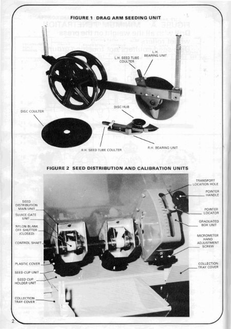
DISC COULTER FIGURE 1 DRAG ARM SEEDING UNlT R.H. SEED TUBE COULTER .= L.H. SEED TUBE L.H. BEARING UNIT - -4 .- .- - : -5; .- - COULTER .-a -1 2 / -. n.n. ormnlluu ulvl I I FIGURE 2 SEED DISTRIBUTION AND CALIBRATION UNITS I DlSTRlBUTlO NYLON BLANK OFF SHUTTER TRANSPORT LOCATION HOLE POINTER GRADUATED MICROMETER CONTROL SHAFT ADJUSTMENT - SCREW SEED CUP UNIT SEED CUP HOLDER UNlT \ - 27 COLLECTION TRAY COVER - COLLECTION T R A Y COVER ,
\ is adapted to, and fits the shape of all kinds of seed: large or small, heavy or light, round or long. An anti- The All-Till seedbed drills will sow most seeds into a variety of seedbeds. They can be used for conventional seedbeds with remarkable accuracy of depth of seed placement, also they can be used in minimum tillage, scratch tillage, direct drilling or no-till situations. The unique high inertia coulter system, with press wheel, maintains constant depth of seed placement under such a variety of conditions, including trashy and straw incorporated' soils, at higher speeds than most drills can accomodate. The All-Till seedbed drills consists'bf a row of independent drag arm seeding units which are spring mounted to the main frame. Each unit consists of 2 discs and 2 press wheel rollers, - the discs are mounted each side of the drag arm at opposite angles. A seed tube coulter is mounted on the inside of each disc, in a position which enables the seed to be placed in a slit cut by the disc. The press wheel rollers are mounted to the rear of the drag arms behind the discs, rolling directly over the slits. 2. SPECIFICATION Sowing Width Overall Width Total Weight No. of Coulters Row Width Seedbox Capacity 3. WORKING PRINCIPLE 3000m m 2960mm 2050Kg. 18 166mm 600 litres When the drill is in the raised position, the weight of the machine is carried on the two land wheels and the tractor drawbar. As the machine is lowered, the disc coulters and press wheels touch the ground, meet resistance from the soil, and begin to compress the springs rttached toeach end of thedrag arm seeding units -the frame can be lowered until all theavailable weight of the machine is supported on the springs. The penetration of the discs and hence the seed depth is controlled by the depth adjusting screw. This alters the relationship between the discs and the roller press wheels; weight can be transferred from the rollers to the discs or vice-versa (See Figs A and B). As each drag arm is separately sprung both front and back, each unit is able to follow ground contours independently. As the drill is drawn forward, the inclined disc opens a slit and the seed tube coulter acts like a tine to prepare a tilth into which the s'eeds are dropped. The roller press wheels then consolidate to ensure good seed/soil contact and moisture retention. 4. TRANSPORT The drill is raised and lowered hydraulically and locking pins are provided for road transport. When the drill is in work the tractor hydraulic control valve should be in the fully floating position so that the road wheels may ride freely over undulating ground conditions. A double acting hydraulic ram is fitted to the drill. To raise the road wheels completely from the ground when the drill is in work, a second hydraulic hose can be fitted. Both hydraulic hoses should be connected to the spool valve on the tractor. Always keep the road wheels fully raised while the drill is in work, so as not to affect the depth control of the drill in undulating fields. For transportation or moving the drill from field to field always ensure that the road transport pins are fitted. Also, the seed distribution units can be closed by pushing the pointer handle to the top of the graduation scale. It can be locked in this position by dropping the locator intothetransport location hole. 5. DEPTH CONTROL This is achieved by turning the depth adjusting screw to raise or lower the discs to the required depth in different field conditions and seed requirements; turning the screw clockwise increases depth, while turning the screw anti-clockwise reduces the depth. Care must be taken with this setting to achieve correct seed depth and effective pressing with the rear press wheels. To increase penetration of the discs, especially in hard ground, or in a direct drilling situation, turn the drawbar over, with the ring hitch on top. This will achieve the same effect as lowering the hitch point on the tractor. 6. SEEDBOX (See Figs. 2 and 3) Each seed distribution unit of the <strong>Moore</strong> All-Till Seedbed Drills is supplied with seed from the hopper by means of a seed feed box. The variable opening of the distribution unit regulates the seed rate. At the lowest part of the feeding box, a plastic feed rotor, operated by the stalker drive wheel, supplies the distribution unit with seed at a high degree of unitormity. Made of flexible plastic(Luco1en) the feed rotor