7400 - 7509.pdf - Moore Unidrill
7400 - 7509.pdf - Moore Unidrill
7400 - 7509.pdf - Moore Unidrill

You also want an ePaper? Increase the reach of your titles
YUMPU automatically turns print PDFs into web optimized ePapers that Google loves.
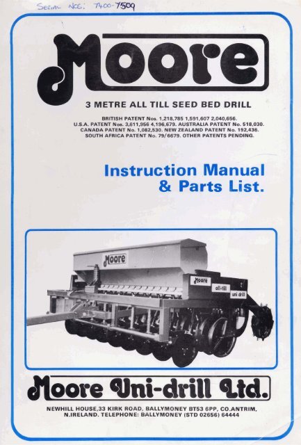
3 METRE ALL TILL SEED BED DRILL<br />
BRITISH PATENT Nos. 1,218,785 1,591,607 2,040,656.<br />
U.S.A. PATENT NOS. 3,611,956 4,196,679. AUSTRALIA PATENT No. 518,030.<br />
CANADA PATENT No. 1,082,530. NEW ZEALAND PATENT No. 192.436.<br />
SOUTH AFRICA PATENT No. 79/6679. OTHER PATENTS PENDING.<br />
Instruction Manual<br />
% Parts List.<br />
c-<br />
a h<br />
N EWHlLL HOUSE,33 KIRK ROAD, BALLYMONEY BT53 6PP, CO.ANTRIM,<br />
N.IRELAND. TELEPHONE: BALLYMONEY (STD 02656) 64444
APPROXIMATE SEEDING RATES FOR MOORE ALL TILL<br />
SEED BED DRILL<br />
NOTE: This Seed Chart is not a guarantee of the correct ammount of seed to be sown - use it onlyasa<br />
guide for the seed quantities required.<br />
Correct seed rates can be obtained by actuating the Acremeter as follows:<br />
Weigh the seeds in the collection trays provided. The weight of the seed is equivalent to that used<br />
to sow one tenth of an acre.<br />
By adjusting the Micrometer Control Screw, the rate can be varied and the desired seed rate<br />
obtained.<br />
The 34 tooth sprocket should be used when sowing small seeds such as turnips, kale, rape etc.,<br />
especially when mixed with slug pellets, also for larger seeds such as peas beans etc. where less<br />
power is required to turn the rotor.
FIGURE A: MINIMUM PENETRATION<br />
Drill with all the weight on the press<br />
wheel rollers<br />
Disc seed coulters not touching ground<br />
ALSO WINNEH OF THE BURKE TROPHY FOR THE MACHINE OF<br />
OUTSTANDING MERIT AT<br />
-THE ROYAL AGRICULTURAL SOCIETY OFENGLAND SHOW 1976<br />
FIGURE B: MAXIMUM PENETRATION<br />
Drill with all the weight on the disc<br />
seed coulters<br />
Press wheel rollers not touching ground
DISC COULTER<br />
FIGURE 1 DRAG ARM SEEDING UNlT<br />
R.H. SEED TUBE COULTER<br />
.=<br />
L.H. SEED TUBE<br />
L.H.<br />
BEARING UNIT<br />
-<br />
-4<br />
.-<br />
.- - :<br />
-5;<br />
.- -<br />
COULTER .-a -1 2<br />
/<br />
-.<br />
n.n. ormnlluu ulvl I<br />
I FIGURE 2 SEED DISTRIBUTION AND CALIBRATION UNITS I<br />
DlSTRlBUTlO<br />
NYLON BLANK<br />
OFF SHUTTER<br />
TRANSPORT<br />
LOCATION HOLE<br />
POINTER<br />
GRADUATED<br />
MICROMETER<br />
CONTROL SHAFT ADJUSTMENT<br />
- SCREW<br />
SEED CUP UNIT<br />
SEED CUP<br />
HOLDER UNlT<br />
\<br />
-<br />
27 COLLECTION<br />
TRAY COVER -<br />
COLLECTION<br />
T R A Y COVER<br />
,
\ is adapted to, and fits the shape of all kinds of seed: large or small, heavy or light, round or long. An anti-<br />
The All-Till seedbed drills will sow most seeds into a variety of seedbeds. They can be used for<br />
conventional seedbeds with remarkable accuracy of depth of seed placement, also they can be used in<br />
minimum tillage, scratch tillage, direct drilling or no-till situations. The unique high inertia coulter<br />
system, with press wheel, maintains constant depth of seed placement under such a variety of<br />
conditions, including trashy and straw incorporated' soils, at higher speeds than most drills can<br />
accomodate.<br />
The All-Till seedbed drills consists'bf a row of independent drag arm seeding units which are spring<br />
mounted to the main frame. Each unit consists of 2 discs and 2 press wheel rollers, - the discs are<br />
mounted each side of the drag arm at opposite angles. A seed tube coulter is mounted on the inside of<br />
each disc, in a position which enables the seed to be placed in a slit cut by the disc.<br />
The press wheel rollers are mounted to the rear of the drag arms behind the discs, rolling directly over<br />
the slits.<br />
2. SPECIFICATION<br />
Sowing Width<br />
Overall Width<br />
Total Weight<br />
No. of Coulters<br />
Row Width<br />
Seedbox Capacity<br />
3. WORKING PRINCIPLE<br />
3000m m<br />
2960mm<br />
2050Kg.<br />
18<br />
166mm<br />
600 litres<br />
When the drill is in the raised position, the weight of the machine is carried on the two land wheels<br />
and the tractor drawbar. As the machine is lowered, the disc coulters and press wheels touch the<br />
ground, meet resistance from the soil, and begin to compress the springs rttached toeach end of thedrag<br />
arm seeding units -the frame can be lowered until all theavailable weight of the machine is supported on<br />
the springs.<br />
The penetration of the discs and hence the seed depth is controlled by the depth adjusting screw. This<br />
alters the relationship between the discs and the roller press wheels; weight can be transferred from the<br />
rollers to the discs or vice-versa (See Figs A and B). As each drag arm is separately sprung both front and<br />
back, each unit is able to follow ground contours independently. As the drill is drawn forward, the<br />
inclined disc opens a slit and the seed tube coulter acts like a tine to prepare a tilth into which the s'eeds<br />
are dropped. The roller press wheels then consolidate to ensure good seed/soil contact and moisture<br />
retention.<br />
4. TRANSPORT<br />
The drill is raised and lowered hydraulically and locking pins are provided for road transport. When<br />
the drill is in work the tractor hydraulic control valve should be in the fully floating position so that the<br />
road wheels may ride freely over undulating ground conditions.<br />
A double acting hydraulic ram is fitted to the drill. To raise the road wheels completely from the<br />
ground when the drill is in work, a second hydraulic hose can be fitted. Both hydraulic hoses should be<br />
connected to the spool valve on the tractor. Always keep the road wheels fully raised while the drill is in<br />
work, so as not to affect the depth control of the drill in undulating fields.<br />
For transportation or moving the drill from field to field always ensure that the road transport pins are<br />
fitted. Also, the seed distribution units can be closed by pushing the pointer handle to the top of the<br />
graduation scale. It can be locked in this position by dropping the locator intothetransport location hole.<br />
5. DEPTH CONTROL<br />
This is achieved by turning the depth adjusting screw to raise or lower the discs to the required depth<br />
in different field conditions and seed requirements; turning the screw clockwise increases depth, while<br />
turning the screw anti-clockwise reduces the depth. Care must be taken with this setting to achieve<br />
correct seed depth and effective pressing with the rear press wheels.<br />
To increase penetration of the discs, especially in hard ground, or in a direct drilling situation, turn the<br />
drawbar over, with the ring hitch on top. This will achieve the same effect as lowering the hitch point on<br />
the tractor.<br />
6. SEEDBOX (See Figs. 2 and 3)<br />
Each seed distribution unit of the <strong>Moore</strong> All-Till Seedbed Drills is supplied with seed from the hopper<br />
by means of a seed feed box. The variable opening of the distribution unit regulates the seed rate. At the<br />
lowest part of the feeding box, a plastic feed rotor, operated by the stalker drive wheel, supplies the<br />
distribution unit with seed at a high degree of unitormity. Made of flexible plastic(Luco1en) the feed rotor
f FIGURE<br />
21 T DRIVE -.<br />
SPROCKET<br />
3 SEEDBOX FIGURE 4 EMPTYING SEED BOX<br />
FIGURE 5 CALIBRATION<br />
j bt .& - . *. A,'"<br />
a. 9<br />
~-.r -- -<br />
"<br />
SEED<br />
-CALIBRATION<br />
& UNIT<br />
, 8.t<br />
-2 -<br />
, Ib .- r. .-p&?.G A<br />
&& TRAY<br />
/<br />
COLLECTION<br />
/LACREMETER
compaction plate can be fitted over the seed feed boxes to give less damage to the larger, more easily<br />
damaged seeds such as soya beans or peas.<br />
A micrometer hand control screw is used to adjust the openings of the seed distribution units for<br />
precise seed rate settings.<br />
7. CALIBRATION (See Fig.5)<br />
The Seed Charts are not a guarantee of the correct amount of seed to be sown - use them only as a<br />
guide to the seed quantities required. Compilation of a Seed Rate Chart is not possible due to variations<br />
in seed types and seed mixtures. Mso the type and quantity of seed dressings used .<br />
To check the Seed Rate, set the calibration pointer to the reading asgiven in the Seeding Tables: open<br />
the covers protecting the distribution units and hinge them down to form collection trays for the seeds.<br />
Release the spring loaded locating pins at each of seed cup holder unit and slide it forward so that the<br />
seed collection trays are underneath the outlets of the seed distribution units.<br />
Ensure that the handle is turned so that the drive wheel turns in the normal direction of travel.<br />
Partially fill the seedbox and actuate the acremeter 100 times. 43 turns of the handle when attached<br />
to the 21 tooth seedboxsprocket. 26 turns of the handle when attached to the 34tooth seedboxsprocket.<br />
Remove the collection trays and weigh the seed: this will represent the seed rate for one-tenth of an acre.<br />
Multiply by 10 to obtain the Seed Rate Per Acre. By adjusting the micrometer control screwthe ratecan<br />
be varied and the desired Seed Rate obtained.<br />
By using the 34 tooth seedbox drive sprocket, the rotor drive shaft is turned slower and thus a larger<br />
opening of the seed distribution units is necessary to get the required seed rate per acre. 'This is useful<br />
when sowing small seeds such as turnips, kale, rape, etc., especially when mixed with slug pellets and<br />
also for large seeds such as, peas, beans etc., where less power is required to turn the rotors.<br />
8. SEEDING AT DIFFERENT ROW WIDTHS<br />
It is possible to sow seeds at row widths of 6Y2in. (1 6.5cms.), 13in., (33 crns.), 19%ins., (49.5cms.), and<br />
26 ins., (66 crns.).<br />
Blank off the seeding units not required by turning the nylon blankoff shutters to closethe openings of<br />
the seed distribution units, as shown in Fig.2.<br />
For small seeds, such as kale, rape, turnips etc., seed container boxes can be securely mounted over<br />
the required seed feed boxes as shown in Fig. 3.<br />
9. EMPTYING SEEDBOX (See Fig. 4)<br />
To empty the seedbox, remove the collection tray/covers. Release the seed cup holder unit and slide it<br />
fully forward. Slacken the screw and channel retaining bracket so that the seedbox fixing arm is free.<br />
Open the seedbox lid and secure with the stay bracket. Pivot the seedbox backwards as shown in Fig. 4.<br />
Open the seed hopper emptying covers and remove the seed into a tray or bag.<br />
10. ACREMETER<br />
The acremeter is actuated by a linkarm attached to the end of the double drive sprocket. The<br />
adjustable arm on the end of the meter should be positioned so that the linkarm is free when the end of<br />
the crank is at the top of its stroke.<br />
The acremeter is calibrated so that it takes 1000 actuations to read 1 acre, therefore, only the first 2<br />
digits read the acres and the last 2 digits the decimal fraction of an acre.<br />
The acremeter can be set to Zero by turning the ribbed knob on the end of the meter<br />
1 1. MAINTENANCE<br />
A. NUTS AND BOLTS<br />
All nuts and bolts should be checked regularly. When working in stony or trashy conditions it will be<br />
necessary to check all nuts and bolts daily, particularly the seed tube coulters and disc bolts.<br />
B. BEARINGS<br />
Check disc and press wheel bearings for correct adjustment.<br />
1 " Dia. Timken Duo SealTaper Roller Bearingsarefitted tothe press wheelsand disc hubson thedrill.<br />
Remove the dust cover and use a socket on the lock nut to tighten up the two taper roller bearings so<br />
that they can just turn freely. When the bearings are slack the rubber seals will wear thus allowing in<br />
dust, ending up with a dry bearing. The bearings are packed with Shell Alvania Grease.
C. SEED TLlBE COLILTER ADJUSTMENT<br />
Check the position of the seed tube coulters in relation<br />
to the disc coulters daily.<br />
For most seeding conditions and as a general rule the tip F<br />
of the seed tube coulter should be set so that it is<br />
approximately l/z " above the outer edge of the disc.. The<br />
leading edge of the seed coulter should be set parallel to<br />
the disc and just touching it. This can be achieved by<br />
means of the retaining bolts-A an& B and the adjusting<br />
screws C and D. If the tip, F, of the seed coulter is out from<br />
the disc, this can be corrected by tightening bolt A (front<br />
bolt) more than bolt B, while the top, G of the seed coulter<br />
can be brought in towards the disc by tightening bolt B (rear<br />
bolt) more than bolt A.<br />
Some discs, may be slightly distorted, but when in workthe side force of the soil on the disc will keep it<br />
in contact with seed coulter. A certain amount of bedding in and wear takes place between the disc and<br />
the seed coulter and it may become necessary to adjust screws C and D to position the seedcoulter closer<br />
to the disc.<br />
12. OPERATION OF ALL-TILL SEEDBED DRILLS<br />
A. PREPARATION AND CALIBRATION<br />
Attach the drill to the tractor and raise thedrill to its maximum height, removethe road transport pins.<br />
Calibrate the seeding mechanism for seeds to be sown.<br />
B. RUNNING IN<br />
If thedrill is new and is to be used in cultivated soil, it is betterto'run-in'thedrill in hard ground, such<br />
as a grass field. It is easier to work off the paint and rough edges from the seed tube and disc coulters<br />
when working in firm ground where there is more friction toturn thediscs. 'This only requires a few runs<br />
across a field, without seed. The depth control of the All-Till seedbed drill can be tried out by turning the<br />
depth control screw up or down to increase or decrease the depth of disc penetration. Check that all the<br />
discs turn relatively freely; it may be necessary to slacken off seed tubes that are rubbing tight against the<br />
discs.<br />
C. FIELD OPERATION<br />
Do not turn sharp corners with the All-Till seedbed drills, especially in direct drilling operations asthis<br />
will give wrong disc-to-soil side thrust. When this happens the disc is parted from the seed coulter and<br />
trash can then enter between them resulting in blockage to the seed flow. It is better to lift the machine<br />
out of and into work when turning corners.<br />
D. WORK RATE<br />
As there is no disc bounce, due to the high inertia coulter system with press wheels, relatively high<br />
ground speeds can be tolerated giving high work rates. 'The operating speed and the quality of work<br />
which results is controlled by field conditions but wherever possible a steady speed should be<br />
maintained. As field conditions vary, it may be necessary to adjust the coulter settings to maintain seed<br />
depth and cover.<br />
E. SEEDBED PREPARATION<br />
It is not necessary to prepare a fine seedbed as for other drills. The All-Till seedbed drill prepares its<br />
own mini seedbed by using angled disc and seed tube coulter tine. In most fields it is only necessary to<br />
plough and perhaps level and roll. If the soils are loose, puffy, soft or have loosestoneson thesurface, it<br />
will generally be advantageous to roll the field first. This will reduce blockages and help maintain even<br />
depth control.<br />
F. DRILLING IN CONVENTIONAL SEEDBED<br />
When working in cultivated soil, most of the drill weight is carried on the press wheel rollers and<br />
tractor drawbar. Seed depth can be obtained by adjusting the depth control screw in the usual manner.<br />
The soil is usually tracked to the depth required by the disc seeding units and compacted by the press<br />
wheel rollers - this gives ideal conditions for seed germination.<br />
It is recommended that the centre of the field should be drilled first and the headlands last. If the<br />
headlands are planted first, then the tractor and drill will travel and turn on planted ground, thus<br />
disturbing, compacting and moving seeds that have been placed at a constant depth. Check seeding<br />
depth in the field and on headlands, remember the headlands tend to be more compacted than the<br />
remainder of the field.<br />
On rough type seedbeds the drill itself tends to be self levelling. The seed tube and disccoulter units<br />
tend to move the soil from humps to hollows. It is not necessary to harrow and roll after sowing.
Harrowing will move seeds either shallower or deeper thus giving uneven germination. Remember<br />
seeds that are planted two to three inches deep take about two weeks longer to germinate and appear as<br />
weak plants, that are susceptible to disease.<br />
G. DRILLING IN WET CONDITIONS<br />
The All-Till seedbed drills are now fitted with adjustable scrapers for the press wheels. Wet soil will<br />
usually build up to about one inch on any wheel. Adjust the scrapers so as to knock off the excess soil that<br />
would build up over the normal amount of soil that sticks to the press wheels.<br />
Never reverse the drill with the seedtube coulters in the ground as this would block the seed outlets<br />
with soil.<br />
Where there are very wet pockets of soil in some fields, the road wheels can be used to slightly raise<br />
the drill out of the ground thus assisting the drill through the difficult areas. Be careful not to raise the<br />
drill too high; always keep the seed drive wheel in contact with the ground.<br />
H. DRILLING INTO STRAW INCORPORATED SOIL AND TRASHY CONDITIONS<br />
In heavy trash conditions it may be necessary to raise the tip of the seed tube coulters, sothat thedisc<br />
will cut through the trash before the coulter opens the slit. In heavy maize trash, especially in the direct<br />
drill or no-till situation, it may be necessary to raise the tip of the seed tube coulter 1 "to 1 %" above the<br />
edge of the disc.<br />
The discs cut through the trash very positively. The weight of the press wheels keep the discs<br />
anchored and do not allow the discs to ride out of the soil, even when there is a lot of trash present.<br />
Bulldozing normally occurs when a disc meets trash, tries to ride up over the trash, then pushes it in<br />
front of the disc, thus causing bulldozing and blockages.<br />
The trash itself, on decaying, produces acids, toxins, etc., which tend todamageor kill the germinating<br />
seed. If the trash is mixed with the soil and compacted tightly togive good straw/soil contact then the soil<br />
will absorb the toxins as they are formed, before they can harm the germinating seedlings. The press<br />
wheels on the All-Till seedbed drills compacts the trash/soil/seed exactly right to give very healthy<br />
plant stands even in very trashy conditions.<br />
If straw is incorporated into the soil to leave a loose fluffy seedbed then it is betterto compact this first<br />
using either a roller, crumbler bar, flexicol, etc., before drilling.<br />
I. MINIMUM TILLAGE AND DIRECT DRILLING<br />
In certain soils, especially if they contain stone or brash, it is recommended that the top 1 " or.2 "<br />
should be cultivated or scratch tilled. This will encourage the germination of volunteer cereals and weed<br />
seeds. It will also help to level out the tramline and wheeled tracks. Also if stones are left undisturbed in<br />
the top layer, they become embeded and the disc will ride from stone to stone without getting good<br />
penetration.<br />
In soft field conditions it is essential to set thediscs deep enough to cut through all the matt or surface<br />
trash. Seed will germinate and grow better when in contact with the soil. In wet, soft conditions thediscs<br />
may be set to penetrate deeper than required. As the drill movesforward the seed is trapped by the sides<br />
of the slit and do not necessarily fall to the bottom of the slit.<br />
J. OTHER SUGGESTIONS<br />
If no air line or vacuum is available to assist in the cleaning out of the seedbox, paper tissues can be<br />
used. Fully open the seed distribution units, wrap up a large paper tissue and place it between the rotor<br />
and seed feed box. Turn the rotor so that it will take the tissue around the bottom of the seed feed box<br />
wiping it clean.<br />
With certain types of peas, beans, etc., the large seeds tend to catch between the rotor and bottom of<br />
the seed feed box, thus splitting and damaging the seeds. Some users keep and use a second set of rotors<br />
from which about 'A " has been cut off the end of the plastic rotors. With the shorter rotors, the large<br />
seeds will not jam between the rotor ends and the bottom of the seed feed box. Less power will be<br />
required to turn the drive wheel and less damage to the seeds will occur.<br />
With small seeds such as oilseed rape, especially if they are covered with seed dressings, it is<br />
important to check the flow of seedsfrom the distribution units. The dressings, especially when damp,<br />
tend to build up around the openings like cement, reducing the size of the opening and thus the seed<br />
rate. A small nail or a length of wire can be used to clear the build up of the dressings.
3 METRE MAIN FRAME & DRAWBAR UNIT<br />
Main Frame<br />
Drawbar Assembly<br />
Drawbar Towing Arm<br />
Drawbar Connecting Pin<br />
Transport Pin<br />
Axle Mountingunit<br />
Ram - Top Pin<br />
Ram - bottom pin<br />
Pivot Collar - Axle Unit<br />
Pivot Bush - Axle Unit<br />
Depth Control Screw Holder<br />
Depth Control Screw<br />
Depth Control Screw-Nut<br />
Depth Control Screw-Tube<br />
Depth Control Screw-Handle<br />
Depth Control Screw - Trunnion<br />
Pivoting Arm Unit<br />
Front Pivot Bar<br />
Spacer Bush - lnner<br />
Spacer Bush - lnner Bushed<br />
Spacer Bush - End<br />
Seedbox Mounting Bracket - R.H.<br />
Seedbox Mounting Bracket - L.H.<br />
1" x 6" UNC Bolt<br />
M20 x 220 Bolt<br />
MI2 x 120 Bolt<br />
MI2 x 100 Bolt<br />
1 lh " x 8'' UNC Bolt<br />
MI0 x 40 Set Screw<br />
1" UNC Locknut<br />
M20 Locknut<br />
MI 2 Locknut<br />
MI0 Locknut<br />
M6 x 50 Split Pin<br />
M8 x 40 Spirol Pin<br />
1 '/a " x 8" Drawbar Pin<br />
2" Timken Thrust Bearing<br />
1 W " Timken Taper Roller Bearing<br />
Oilite Bush<br />
Road Wheel 10.5 x 15.0 x 10 Ply<br />
21h " Dia. Hydraulic Cylinder<br />
Hydraulic Hose/Ram - Traction<br />
96" B.S.P. Tee M.M.F.<br />
Hydraulic Hose/Ram-Ram<br />
Depth Control Sprlng<br />
1 %"x 1 " x 1 " Hardened Bush<br />
1 l/4 " UNC Nut<br />
Seedbox Complete<br />
Rear Platform
Drag Arm Axle Unit<br />
Dragarm Mounting Bar<br />
Press Wheel<br />
Disc Hub<br />
Disc Mounting Bracket - R.H.<br />
Disc Mounting Bracket - L.H.<br />
Seedtube Coulter - R.H.<br />
Seed Tube Coulter - L.H.<br />
Seed Tube Retaining Plate<br />
Press Wheel Scraper<br />
Dragarm Guide Plate - R.H.<br />
Dragarm Guide Plate - L.H.<br />
Guide Plate Bar<br />
Guide Plate Distance Piece<br />
Disc Bearing Replacement Unit - R.H.<br />
Disc Bearing Replacement Unit - L.H.<br />
Front Spring Arm<br />
Front Pivot Sleeve<br />
Front Pivot Bush<br />
Pivot Arm Unit<br />
% " x 4% " UNC. Bolt<br />
M1 6 x 55 Bolt<br />
M1 2 x 75 Bolt<br />
MI 2 x 55 Bolt<br />
MI0 x 65 Bolt<br />
MI0 x 50 Bolt<br />
% x % UNF. Setscrew<br />
M1 0 x 20 Setscrew<br />
?/4 UNC Locknut<br />
% UNF Locknut<br />
% UNF Locknut<br />
M1 6 Locknut<br />
MI2 Locknut<br />
MI0 Locknut<br />
M20 x 32 H.D. Washer<br />
M 16 x 32 H.D. Washer<br />
M 10 Shake Proof Washer<br />
1 " Timken Taper Roller Bearing<br />
1 " Timken Circlip<br />
Olite Bush<br />
Seed Disc Coulter 16" Dia.<br />
Spring Retaining Bush<br />
Spring Locating Bush<br />
Dust Cap - Small<br />
Front Spring - Lower<br />
Front Spring - Upper<br />
Rear Spring - H.D.
3 METRE SEEDBOX 81 DRIVE UNIT<br />
Seed Box Mounting Bracket RH<br />
Seed Box Mounting Bracket LH<br />
Support Arm Pivot Bracket<br />
314-1034 . . Drive Wheel Support Arm - Upper<br />
Drive Wheel Support Arm - Lower<br />
Drive Wheel<br />
Drive Wheel Axle<br />
Drive Wheel Spacer<br />
Pivot Bracket Bearing Washer<br />
Chain Guard Cover<br />
Chain Guard Lower<br />
9T Double Drive Sprocket<br />
12T Drive Sprocket Lower<br />
2 1 T Drive Sprocket Upper<br />
34T Drive Sprocket Upper<br />
Chain Connecting Link<br />
74L Drive Chain - Lower<br />
70L Drive Chain - Upper<br />
M20 x 70 Bolt<br />
MI2 x 55 Bolt<br />
MI 0 x 60 Setscrew<br />
M8 x 16 Setscrew<br />
M6 x 10 Socket Head<br />
% UNF Lock Nut<br />
MI0 Wing Nut<br />
M20 Lock Nut<br />
M12 Lock Nut<br />
MI6 x 32 Washer H.D.<br />
1 % " Timken Taper Roller Bearing<br />
1 " Timken Taper Roller Bearing<br />
Acremeter Link Arm<br />
Dust Cap - Small<br />
Dust Cap - Large<br />
Seed Box Shell<br />
Seed Box Lid<br />
Collection Tray/Cover R.H.<br />
Collection Tray/Cover LH<br />
Seedcup Holder Unit<br />
Rotor Drive Shaft<br />
Distribution Shaft<br />
Anti Compaction Plate<br />
Flexible Seed Tube -sf<br />
Seed Tube Joint<br />
Seed Cup Holder<br />
Large Seed Box<br />
Feed Rotor<br />
Callibration Handle<br />
Distribution - Main Unit<br />
Distribution - Sluicegate Unit<br />
Distribution - Plastic Cover<br />
Distribution - Nylon Shutter<br />
Calibration - Hand Adjustment Screw<br />
Calibration - Spring<br />
Calibration - Adjustment Nut<br />
Calibration - Screw Thread<br />
Calibration - Pointer Shaft<br />
Calibration - Pointer Locator<br />
Calibration - Pointer Handle<br />
Calibration - Graduated Box<br />
Seex Box - Pivot Casting<br />
Seed Box - Bearing Casting<br />
Channel Retaining Bracket