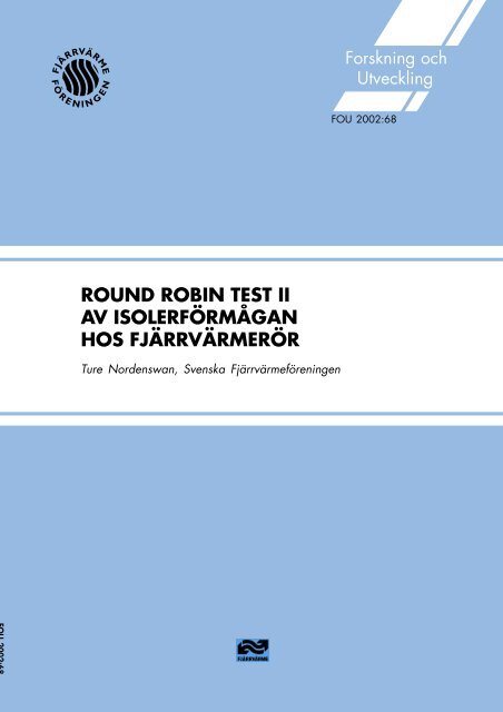
round robin test ii av isolerförmågan hos fjärrvärmerör - Svensk ...
round robin test ii av isolerförmågan hos fjärrvärmerör - Svensk ...
round robin test ii av isolerförmågan hos fjärrvärmerör - Svensk ...

Create successful ePaper yourself
Turn your PDF publications into a flip-book with our unique Google optimized e-Paper software.
ROUND ROBIN TEST II<br />
AV ISOLERFÖRMÅGAN<br />
HOS FJÄRRVÄRMERÖR<br />
Ture Nordenswan, <strong>Svensk</strong>a Fjärrvärmeföreningen<br />
Forskning och<br />
Utveckling<br />
FOU 2002:68
ROUND ROBIN TEST II<br />
AV ISOLERFÖRMÅGAN<br />
HOS FJÄRRVÄRMERÖR<br />
Ture Nordenswan, <strong>Svensk</strong>a Fjärrvärmeföreningen<br />
ISSN 1402-5191<br />
ISSN 1401-9264
I rapportserien publicerar projektledaren resultaten från sitt<br />
projekt. Publiceringen innebär inte att <strong>Svensk</strong>a Fjärrvärmeföreningens<br />
Service AB tagit ställning till slutsatserna och<br />
resultaten.<br />
02-04-24 © 2002 <strong>Svensk</strong>a Fjärrvärmeföreningens Service AB
Innehållsförteckning<br />
Förord 4<br />
Syfte 5<br />
Inledning/bakgrund 5<br />
Metod 6<br />
Resultat 7<br />
Kommentar 9<br />
Sida<br />
Bilaga Originalrapport: ROUND ROBIN TEST FOR THE USE OF<br />
ISO 8497 TO MEASURE THERMAL CONDUCTIVITY IN<br />
PRE-INSULATED PIPES<br />
Acronym Lambda II<br />
NORDTEST Project No 1506-00<br />
Originalrapporten är tillgänglig på<br />
www.nord<strong>test</strong>.org/projects/finalrep/1506-00.pdf
Förord<br />
Projektet genomfördes under 2000-2001 som en fortsättning på ROUND ROBIN TEST AV<br />
ISOLERFÖRMÅGAN HOS FJÄRRVÄRMERÖR FoU 1998:22 som initierades <strong>av</strong> den<br />
arbetsgrupp inom det europeiska standardiseringsarbete som arbetar med utvecklingen <strong>av</strong><br />
standard för <strong>fjärrvärmerör</strong>s isoleringsegenskaper CEN/TC107/WG3.<br />
Den ursprungliga redovisningen <strong>av</strong> projektet finns som bilaga till denna sammanfattning på<br />
svenska. Precis som förra gången ingår även detta fortsättningsprojekt i <strong>Svensk</strong>a<br />
Fjärrvärmeföreningens forskningsserie.<br />
Originalrapporten har titeln ROUND ROBIN TEST FOR THE USE OF ISO8497 TO<br />
MEASURE THERMAL CONDUCTIVITY IN PRE-INSULATED PIPE, Acronym LAMBDA II<br />
och har givits ut <strong>av</strong> NORDTEST med projektnummer 1506-00. Ansvarig för koordineringen<br />
<strong>av</strong> projektet har varit Henning D Smidt, Dansk Teknologisk Institut i Århus, som också<br />
författat originalrapporten. Tillsammans med Rolf Besier från AGFW samt Udo Schilling från<br />
Elastogran, båda från Tyskland, har undertecknad ingått i styrgruppen för projektet.<br />
Omkring 20 laboratorier inbjöds att medverka och 10 <strong>av</strong> dessa deltog i <strong>test</strong>et medan 7<br />
laboratorier blev klara vid tidpunkten för slutredovisning. Testresultaten redovisas öppet.<br />
Spridningen mellan redovisade värden blev denna gång liten. Med ISO8497 som bas och<br />
föreslagna korrigeringar i tillhörande annex elimineras de tvister som förekommit i branschen.<br />
Det lyckade resultatet bör icke minst tillskrivas projektledaren Henning D. Smidt och hans<br />
omsorgsfullt utförda arbete.<br />
Vi önskar också tacka Nord<strong>test</strong> för medgivande <strong>av</strong> publiceringen <strong>av</strong> rapporten i vår FoUrapportserie.<br />
Stockholm 2002-04-20<br />
Ture Nordenswan<br />
4
Syfte<br />
Föregående ring<strong>test</strong>, Round Robin I, hade till syfte att identifiera, studera och värdera de<br />
mätmetoder som vid den tidpunkten användes för bestämning <strong>av</strong> värmekonduktiviteten <strong>hos</strong><br />
<strong>fjärrvärmerör</strong>. Härvid användes olika metoder, standarder och rörlängder för att fastställa<br />
värmekonduktiviteten.<br />
Syftet denna gång har varit att utforma en provmetod baserad på ISO8497 Thermal insulation<br />
- Determination of steady state thermal transmission properties of thermal insulation for<br />
circular pipes med samtidig verifiering <strong>av</strong> resultaten.<br />
Inledning/bakgrund<br />
Prefabricerade <strong>fjärrvärmerör</strong>, som omfattas <strong>av</strong> detta projekt, består <strong>av</strong> ett inre medieförande<br />
rör <strong>av</strong> stål, direktapplicerade PUR-isolering och med en mantel <strong>av</strong> polyeten. PUR-isoleringen<br />
består <strong>av</strong> ett stort antal små slutna celler som innehåller en blandning <strong>av</strong> luft och koldioxid.<br />
Fjärrvärme som uppvärmningsform finns i ett stort antal länder med en speciell koncentration<br />
till Norden, Tyskland och Östeuropa. I Europa produceras årligen cirka 10 000 km isolerade<br />
rör <strong>av</strong> denna konstruktion för att användas vid fjärrvärmedistribution.<br />
Inom det europeiska standardiseringsarbetet finns provmetoder och kr<strong>av</strong>nivåer för<br />
<strong>fjärrvärmerör</strong> beskrivna i standarden EN 253. För bestämning <strong>av</strong> värmekonduktiviteten, eller<br />
-värdet, <strong>av</strong> polyuretanisoleringen hänvisas till standarden ISO 8497 Thermal Insulation -<br />
Determination of steady-state thermal transmission properties of thermal insulation for<br />
circular pipes. Denna standard gäller för isolering <strong>av</strong> rör, ej specifikt för prefabricerade<br />
<strong>fjärrvärmerör</strong>, vilket innebär att metodbeskrivningen i ISO 8497 inte direkt går att applicera<br />
på <strong>fjärrvärmerör</strong>, eftersom stålrör, polyuretanisolering och polyetenhölje bildar en<br />
sammanhängande konstruktion och följaktligen måste provas som en konstruktion och inte<br />
som om vore det ett homogent isoleringsmaterial.<br />
Värmekonduktiviteten <strong>hos</strong> <strong>fjärrvärmerör</strong> är en viktig marknadsföringsparameter. Om olika<br />
provningslaboratorier redovisar varierande värden för samma produkt, innebär det att<br />
bedömningsgrunderna för val <strong>av</strong> fabrikat och beräkning <strong>av</strong> verkliga energiförluster inte blir<br />
korrekta.<br />
5
Metod<br />
De <strong>fjärrvärmerör</strong> som skulle provas tillverkades denna gång enligt standardmetod med<br />
koldioxidblåst isolering. Rören DN 50/140 åldrades i 250 dygn vid 90 o C temperatur. Denna<br />
tid motsvarar 12,3 år för CO2, 8,6 år för O2 och 6,0 år för N2 vid 25 o C vilket betyder att rören<br />
endast försumbart förändrats under själva provtiden på de olika provplatserna.<br />
De deltagande laboratorierna erhöll 3 stycken <strong>fjärrvärmerör</strong> vardera slumpvis uttagna för<br />
provning.<br />
Samtidigt distribuerades ett frågeformulär för att undersöka mätmetoder, utrustning och<br />
förhållandena under mätningarna. Frågor och svar finns också med som bilagor i rapporten.<br />
Förra gången var rören DN50/125 tillverkade enligt en kontinuerlig process med förslutna<br />
ändar och åldrade i 11 dygn i 70 o C. Rören innehöll cyklopentan.<br />
FEM-beräkningar visar att distansernas inverkan är försumbar då inverkan i ett helt rör endast<br />
är 0,0002 W/(mK).<br />
6
Resultat från mätningarna <strong>av</strong> värmekonduktiviteten<br />
Laboratorium Provbit<br />
nr.<br />
Värmekonduktivitet<br />
W/(m K)<br />
Medelvärde<br />
W/(m K)<br />
Standard<br />
<strong>av</strong>vikelse<br />
W/(m K)<br />
95% Konfidensintervall<br />
W/(m K)<br />
LUT 15 0,0366 0,0358 0,0007 0,0351 0,0366<br />
17 0,0353<br />
22 0,0356<br />
IG 1 0,0362 0,0364 0,0003 0,0361 0,0367<br />
31 0,0366<br />
22 0,0360<br />
APFS 9 0,0368 0,0365 0,0004 0,0361 0,0369<br />
18 0,0365<br />
27 0,0361<br />
FIW 5 0,0363 0,0369 0,0006 0,0362 0,0376<br />
14 0,0375<br />
26 0,0369<br />
CTH 7 0,0367 0,0369 0,0002 0,0366 0,0371<br />
16 0,0371<br />
24 0,0368<br />
DTI 11 0,0364 0,0360 0,0005 0,0355 0,0365<br />
25 0,0360<br />
28 0,0355<br />
IMA 8 0,0365 0,0366 0,0001 0,0365 0,0367<br />
13 0,0367<br />
23 0,0366<br />
Totalt 0,0364 0,0004 0,0359 0,0369<br />
LUT Lappeenranta University of Technology, Finland<br />
IG Instituto Giordano SpA, Italien<br />
APFS Alstom Power Flow Systems, Danmark<br />
FIW Forschungsinstitut fur Wärmeschutz eV Munchen, Tyskland<br />
CTH Chalmers Tekniska Högskola, Sverige<br />
DTI Dansk Teknologisk Institut, Danmark<br />
IMA Materialforschung und Anvendungstechnik GmbH, Tyskland<br />
38<br />
37,5<br />
37<br />
36,5<br />
36<br />
35,5<br />
35<br />
34,5<br />
34<br />
DTI LUT IG IMA APFS CTH FIW<br />
7
Nedan visas resultaten grafiskt, enheten är mW/(mK)<br />
Provmetoderna har således varit möjliga att justera så att medelvärdena <strong>hos</strong> de olika<br />
laboratorierna ligger mellan 35,5 och 37,5 mW/(mK) vid medeltemperaturen 50 o C.<br />
Standard<strong>av</strong>vikelsen är 1,2% vilket är acceptabelt. Detta bygger på resultat från de 7<br />
laboratorier som lämnade uppgifter före det <strong>av</strong>slutande mötet.<br />
Resultaten som redovisades förra gången låg för 10 <strong>av</strong> de 11 deltagande laboratorierna mellan<br />
25,8 och 32,1 mW/(mK). För ett <strong>av</strong> laboratorierna låg värdet på 37,1. Rören var den gången<br />
tillverkade med cyklopentan, vilket förklarar de generellt sett lägre värdena.<br />
Rörens homogenitet<br />
Resultatet <strong>av</strong> provrörens homogenitet följer <strong>av</strong> nedanstående tabell<br />
Rörnummer 11 28 - EN 253<br />
Densitet g/cm³ 58,7 (3,1) 68,8 (1,5) - >60<br />
Andel slutna celler % 92,3 (0,6) 92,7 (0,6) - >88<br />
Färg Gräddgul Gräddgul - -<br />
Cellstorlek mm 0,21 (0,03) 0,23 (0,05)
Kommentar<br />
Resultaten som redovisades förra gången från 10 <strong>av</strong> 11 laboratorier låg mellan 0,0268 till<br />
0,0321 W/(mK). Rören var blåsta med cyklopentan, vilket förklarar varför värdena låg på en<br />
lägre nivå än denna gång.<br />
Endast 7 <strong>av</strong> de 10 deltagande laboratorierna levererade resultat inför det <strong>av</strong>slutande mötet.<br />
Några smärre justeringar gjordes i annexet till ISO8497. Annexet inklusive justeringar<br />
redovisas i rapporten.<br />
I samband med typ<strong>test</strong> <strong>av</strong> <strong>fjärrvärmerör</strong> föreslås att tre rör <strong>test</strong>as och att resultatet redovisas<br />
med tre siffror. Om 4 siffror används i exempelvis utvecklingssyfte måste osäkerheten<br />
fastställas.<br />
Resultatet kan överlämnas till standardiseringskommittén CEN TC107 för behandling och<br />
inarbetning i standarden EN 253 för <strong>fjärrvärmerör</strong>.<br />
9
Bilaga<br />
Originalrapport: ROUND ROBIN TEST FOR THE USE OF ISO8497 TO<br />
MEASURE THERMAL CONDUCTIVITY IN PRE-<br />
INSULATED PIPES<br />
Acronym LAMBDA II
Bilaga<br />
Originalrapport: ROUND ROBIN TEST FOR THE USE OF ISO8497 TO<br />
MEASURE THERMAL CONDUCTIVITY IN PRE-<br />
INSULATED PIPES<br />
Acronym LAMBDA II
NORDTEST Project No. 1506-00<br />
ROUND ROBIN TEST FOR THE USE OF<br />
ISO8497 TO MEASURE THERMAL<br />
CONDUCTIVITY IN PRE-INSULATED PIPES<br />
Acronym LAMBDA II<br />
Organised by:<br />
Energy Division<br />
Centre for District Heating<br />
Kongsvang Allé 29<br />
DK-8000 Aarhus C
Round Robin Test II<br />
ROUND ROBIN TEST FOR THE USE OF ISO8497 TO MEASURE THERMAL<br />
CONDUCTIVITY IN PRE-INSULATED PIPES<br />
NORDTEST Project No. 1506-00<br />
2. edition, July 2001<br />
Danish Technological Institute, Energy Division<br />
Danish Technological Institute is an independent non-profit enterprise with 1000<br />
employees and an annual turnover of DKK 750 million, corresponding to EUR 100<br />
million. Services provided by the Institute include consultancy, <strong>test</strong>ing, documentation,<br />
information and training.<br />
2
Foreword<br />
Round Robin Test II<br />
This project was initiated by CEN/TC107/WG3, which is the European working group<br />
that puts forward proposals for standards for polyurethane cellular plastic in district<br />
heating pipes.<br />
The project was carried out by an international steering committee with the participation<br />
of the following user organisations: Arbeitsgemeinschaft Fernwärme, Germany, the<br />
Swedish District Heating Association and a producer of raw materials for district heating<br />
pipes - BASF, Germany.<br />
Approximately 20 laboratories were invited, and 10 took part in the Round Robin Test.<br />
The Nordic laboratories were supported partly by NORDTEST (project No. 1506-00),<br />
whereas the other participants paid for their own participation. In addition, the following<br />
companies h<strong>av</strong>e kindly supported the project: ALSTOM Power FlowSystems A/S,<br />
Denmark, Elastogran GmbH, Germany, Huntsman Polyurethanes, Belgium, and Løgstør<br />
Rør A/S, Denmark. Without their contribution it would not h<strong>av</strong>e been possible to<br />
complete this project.<br />
I would like to thank all participants for their support in finishing the project.<br />
Aarhus, July 2001<br />
Henning D. Smidt<br />
Project Manager<br />
3
Summary<br />
Round Robin Test II<br />
Is it possible to use the standard ISO8497 Thermal insulation - Determination of steadystate<br />
thermal transmission properties of thermal insulation for circular pipes together<br />
with an annex when measuring thermal conductivity in pre-insulated pipes? This was<br />
investigated in a Round Robin Test where 7 laboratories participated.<br />
The <strong>test</strong> samples were prepared as water-blown pre-insulated pipes with a steel medium<br />
pipe and a HDPE casing pipe. The <strong>test</strong> samples were artificially aged for 250 days at<br />
90°C. By means of ageing the cell gas content changed to a composition that did not<br />
change the thermal conductivity during the measuring period.<br />
The 7 laboratories received 3 aged random pipes, and measured single results between<br />
0.0353 and 0.0375 W/(m K). The standard variation was in the range of 0.0001 to 0.0007<br />
W/(m K), measured on 3 pipes in relation to a thermal conductivity of 0.036 W/(m K)<br />
that corresponds to 0.3% - 2.0% of the measured value.<br />
The <strong>av</strong>erage results from the laboratories were from 0.0358 to 0.0369 W/(m K) with a<br />
standard deviation in the area of 0.0001 to 0.0007 W/(m K).<br />
The <strong>av</strong>erage of all measurements was 0.0364 W/(m K) with a standard deviation of<br />
0.00043 W/(m K) or 1.2%.<br />
By using FEM analyses it was calculated that the spacers in the entire pipe increase<br />
thermal conductivity by 0.0002 W/(m K).<br />
The applied equipment gives uniform results though 4 laboratories use calculated end<br />
caps, 2 laboratories use guarded ends and 1 laboratory uses calibrated end caps.<br />
There was an overlap between all the laboratories in the 95% confidence interval and<br />
the 95% confidence interval from the <strong>av</strong>erage value of the <strong>test</strong> samples. There was also<br />
an overlap between the 95% confidence interval between most of the laboratories.<br />
Uniform results were obtained from the few laboratories that also measured foam<br />
properties.<br />
In the annex to ISO8497 some minor changes were carried out. The annex included the<br />
corrections stated in the report.<br />
In connection with type <strong>test</strong>ing of pre-insulated pipes it was recommended to <strong>test</strong> 3<br />
pipes and to state the result with 3 digits. If 4 digits are used, e.g. for development<br />
purposes, the uncertainty has to be stated.<br />
4
Table of contents<br />
Round Robin Test II<br />
1 Objective .............................................................................................................................................. 6<br />
2 Introduction .......................................................................................................................................... 6<br />
3 The samples.......................................................................................................................................... 7<br />
3.1 Homogenity ................................................................................. Error! Bookmark not defined.<br />
3.2 Changes by ageing........................................................................................................................ 7<br />
3.3 Determination of the number of <strong>test</strong> pipes.................................................................................... 9<br />
4 Production of <strong>test</strong> pipes ........................................................................................................................ 9<br />
5 Questionnaires ...................................................................................................................................... 9<br />
6 Results ................................................................................................................................................ 10<br />
6.1 Homogeneity............................................................................................................................... 10<br />
6.2 Thermal conductivity.................................................................................................................. 11<br />
6.3 Foam properties .......................................................................................................................... 12<br />
6.4 Questionnaires ............................................................................................................................ 14<br />
6.5 Spacers........................................................................................................................................ 14<br />
7 Conclusions ........................................................................................................................................ 14<br />
8 References .......................................................................................................................................... 15<br />
9 Enclosures .......................................................................................................................................... 15<br />
9.1 Working document TC107 WG3 Sub-group: Thermal conductivity of pre-insulated pipes....... 15<br />
9.2 Organisations and addresses ....................................................................................................... 20<br />
9.3 Questionnaires ............................................................................................................................ 23<br />
5
1 Objective<br />
Round Robin Test II<br />
The objective of the project is to verify the results of the annex and the standard<br />
ISO8497:1994, when measuring thermal conductivity in pre-insulated district heating<br />
pipes.<br />
2 Introduction<br />
The objective of this Round Robin Test was to form a basis for measuring thermal<br />
conductivity in pre-insulated district heating pipes and thereby to obtain more reliable<br />
results. That is why the Round Robin Test Lambda I - Nord<strong>test</strong> report No. 387 (1997) -<br />
was carried out. The result of 40 measurements from 10 laboratories was that thermal<br />
conductivity 50 °C - λ 50 - shows results from 0.0268 W/mK to 0.0321 W/mK. The<br />
standard deviation was from 0.00010 W/mK to 0.00082 W/mK.<br />
A further scrutiny of the results shows that 6 laboratories quote the thermal conductivity<br />
of the foam while the other 5 state the results of the entire pre-insulated pipe. Of the<br />
participating laboratories 6 of them measure according to DIN52613:77. One laboratory<br />
carries out measurements according to ISO8497:94, one according to ISO/DIS8497:88,<br />
one according to ASTM C335-69 and 2 laboratories according to their own method. The<br />
standard EN253:94 prescribes ISO 8497.<br />
On the basis of the results and simultaneously collected information regarding the<br />
circumstances of the measurements, a number of recommendations were stated. These<br />
recommendations are proposed as an annex to ISO8497, when the standard is used for<br />
measuring thermal conductivity in pre-insulated pipes.<br />
The objective of this Round Robin Test is to verify the results when the annex is used<br />
together with ISO8497:1994.<br />
6
3 The samples<br />
3.1 Homogeneity<br />
Round Robin Test II<br />
It is necessary to investigate the following properties of the foam: density, colour homogeneity,<br />
cell size, including voids and bubbles, and the composition of cell gas to ensure<br />
that the specimens are homogeneous in composition. The closed cell content will form<br />
part of this investigation. In addition to this, it is necessary to determine geometric conditions<br />
such as diameter, coaxiality and jacket pipe thickness to ensure that homogeneous<br />
<strong>test</strong> pipes are obtained.<br />
3.2 Changes by ageing<br />
Pre-insulated pipes change thermal conductivity during ageing because of diffusion of<br />
cellular gases. With the object to obtain <strong>test</strong> pipes with constant thermal conductivity it<br />
was decided to use water-blown PUR foam and to artificially age the <strong>test</strong> pipes in an<br />
oven. The calculated change in cellular gas is shown below.<br />
2<br />
2<br />
P () t<br />
1.8<br />
1.6<br />
Par<br />
tial P<br />
pre<br />
() t 1.4<br />
ssu<br />
re<br />
P 2 () t<br />
1.2<br />
1<br />
P () t<br />
P () t<br />
cP<br />
0<br />
0.8<br />
0.6<br />
0.4<br />
0.2<br />
0<br />
0 5 10 15 20 25 30<br />
0 t<br />
Total<br />
CO2<br />
O2<br />
N2<br />
cyclopentane<br />
yr<br />
Time [years]<br />
Figure 1: The calculated change in cellular gas in a PUR water-blown pre-insulated pipe,<br />
dimension 60.3 steel pipe in140 mm HDPE casing pipe.<br />
30<br />
7
On the basis of this, thermal conductivity can be calculated - see below.<br />
Lambda [W/(m K)]<br />
Figure 2: The calculated change in thermal conductivity in a PUR water-blown pre-<br />
insulated pipe, dimension 60.3 steel pipe in 140 mm HDPE casing pipe.<br />
Round Robin Test II<br />
The activation energy for permeability of the simple cellular gases CO2, O2 and N2 is<br />
determined from 5 °C till 40 °C by Olson. As no physical changes occur in the structure<br />
of HDPE in the temperature range from 40 °C to 90 °C, the determined activation energies<br />
can be used to calculate the relationship between time and temperature in the temperature<br />
range by using the Arrhenius equation.<br />
Air Activation Energy<br />
[J/mol]<br />
CO2 40 x 10 3<br />
35 x 10 3<br />
O2<br />
0.040<br />
0.04<br />
0.038<br />
0.036<br />
0.034<br />
0.032<br />
0.03<br />
0.028<br />
λ m() t<br />
0.026<br />
0.024<br />
λ sol<br />
0.022<br />
λ rad<br />
0.02<br />
0.018<br />
λ m() t + λ sol+<br />
λ rad0.016<br />
0.014<br />
0.012<br />
0.01<br />
0.008<br />
0.006<br />
0.004<br />
0.002<br />
0 0<br />
0 5 10 15 20 25 30<br />
0 t<br />
yr<br />
Time [years]<br />
Gas<br />
Solid<br />
Radiative<br />
Foam<br />
Time at 90 °C Time at 25 °C Time at 25 °C<br />
[Days]<br />
[Days]<br />
[Years]<br />
250 4494 12.3<br />
250 3132 8.6<br />
N2 30 x 10 3 250 2182 6.0<br />
Table 1: The relationship between time and temperature for permeation of gas<br />
through HDPE.<br />
If the figure in the column called “Years” in table 1 is compared with figure 3.2 it appears<br />
that thermal conductivity will remain almost constant.<br />
30<br />
8
3.3 Determination of the number of <strong>test</strong> pipes<br />
Round Robin Test II<br />
It is required that an error of 1 mW/mK can be detected, i.e. the result can be stated, e.g.<br />
0.030 ± 0.001 W/mK. The Standard Deviation was determined at 0.00039W/m K in the<br />
Lambda 1 project.<br />
When the number of samples are to be determined, the STD is to be multiplied by a<br />
factor of 0.001/0.00039 = 2.56. From a student t-<strong>test</strong> table it can be found that the first<br />
figure is smaller than 2.59 for the 95% level is 2.48. That means that 3 samples are to be<br />
measured.<br />
4 Production of <strong>test</strong> pipes<br />
The specimens were of the dimension DN50 i.e. d/D 60.3/140 mm with a casing pipe<br />
thickness of 2.5 mm. The cellular plastic was water-blown polyurethane while the casing<br />
pipe material was a standard product.<br />
Normally, the dimension d/D 60.3/125 is c<strong>hos</strong>en to measure thermal conductivity. In this<br />
<strong>test</strong> it was desired that the <strong>test</strong> samples should h<strong>av</strong>e constant thermal conductivity. That<br />
was the reason why water-blown foam was used. Water-blown foam has a higher thermal<br />
conductivity than normal cyclopentane blown foam. On the other hand, the heat flow<br />
during the <strong>test</strong> should be the same. Therefore, an oversize pipe was c<strong>hos</strong>en.<br />
The pipes were blown in the traditional way. The pipes were 5.5 m long and cut to 4.5 m<br />
before ageing at 90 °C. After ageing for 250 days at 90 °C the pipes were randomised<br />
before labelling and distribution to the laboratories.<br />
5 Questionnaires<br />
With the purpose of obtaining knowledge of the measuring method, the equipment and<br />
the circumstances during measuring, a questionnaire was prepared. The questions and the<br />
answers can be seen under enclosures, chapter 9.3.<br />
9
6 Results<br />
Round Robin Test II<br />
Only 7 of the 10 laboratories supplied the results before the final meeting. The results<br />
from these laboratories are included in the data below.<br />
6.1 Homogeneity<br />
The results of the homogeneity <strong>test</strong> of the samples are shown below:<br />
Pipe # 11 28 -<br />
EN253<br />
Density g/cm 3 58.7 (3.1) 68.8 (1.5) - > 60<br />
Closed cell content % 92.3 (0.6) 92.7 (0.6) - > 88<br />
Colour Cream Cream - -<br />
Cell size mm 0.21 (0.03) 0.23 (0.05)<br />
< 0.05<br />
Voids and bubbles<br />
Diameter<br />
mm<br />
mm<br />
-<br />
141<br />
-<br />
143.5<br />
-<br />
-<br />
< 5<br />
140 – 141.3<br />
Centre line deviation<br />
Casing pipe thickness<br />
mm<br />
mm<br />
1.4<br />
2.9<br />
1.7<br />
3.0<br />
-<br />
-<br />
3.0<br />
3.0 – 3.5<br />
Pipe no. 07 16 24 -<br />
Air (N2+ O2) kPa 37.4 49.5 44.8 -<br />
CO2<br />
kPa 5.5 4.5 4.7 -<br />
Water kPa 1.3 1.6 1.3 -<br />
Others kPa 1.3 1.3 2.1 -<br />
Table 2: The table shows the results of the homogeneity <strong>test</strong>s carried out by DTI on end<br />
pieces from <strong>test</strong> pipes. Chalmers Tekniska Högskola carried out the cell gas<br />
analyses. ( ) are STD.<br />
As can be seen from table 4, the <strong>test</strong> pipes meet the requirements of the standard except<br />
for the density and diameter. The density measured in the middle of the samples by other<br />
laboratories meets the requirements – see table 6. The calculation of thermal conductivity<br />
includes the diameter. That means that the samples meet the requirements for <strong>test</strong> pipes.<br />
There is still a carbon dioxide content although it is low. This means that thermal<br />
conductivity will continue to increase.<br />
10
6.2 Thermal conductivity<br />
The measured values and a graphical presentation of the results is seen below.<br />
Lab<br />
no.<br />
Lab.<br />
abb<br />
Pipe<br />
no.<br />
Thermal<br />
conductivity<br />
W/(m K)<br />
Average<br />
W/(m K)<br />
Standard<br />
deviation<br />
W/(m K)<br />
95% Conficence<br />
Interval<br />
W/(m K)<br />
1 LUT 15 0,0366 0,0358 0,0007 0,0351 0,0366<br />
17 0,0353<br />
22 0,0356<br />
2 IG 1 0,0362 0,0364 0,0003 0,0361 0,0367<br />
31 0,0366<br />
22 0,0360<br />
3 APFS 9 0,0368 0,0365 0,0004 0,0361 0,0369<br />
18 0,0365<br />
27 0,0361<br />
4 FIW 5 0,0363 0,0369 0,0006 0,0362 0,0376<br />
14 0,0375<br />
26 0,0369<br />
5 CTH 7 0,0367 0,0369 0,0002 0,0366 0,0371<br />
16 0,0371<br />
24 0,0368<br />
6 DTI 11 0,0364 0,0360 0,0005 0,0355 0,0365<br />
25 0,0360<br />
28 0,0355<br />
7 IMA 8 0,0365 0,0366 0,0001 0,0365 0,0367<br />
13 0,0367<br />
23 0,0366<br />
Total 0,0364 0,0004 0,0359 0,0369<br />
Table 3: The table shows the results of the Round Robin Test.<br />
W/(m K)<br />
0,0380<br />
0,0375<br />
0,0370<br />
0,0365<br />
0,0360<br />
0,0355<br />
0,0350<br />
Thermal Conductivity<br />
1 2 3 4 5 6 7 Lab no.<br />
Figure 3: The picture shows the <strong>av</strong>erage and the 95% confidence interval.<br />
Round Robin Test II<br />
11
Round Robin Test II<br />
The results vary from 0.0355 to 0.0375 W/mK. The <strong>av</strong>erage is 0.0364 W/(m K) with a<br />
standard deviation of 0.00043 W/(m K) or 1.2% of the <strong>av</strong>erage.<br />
The standard variation is in the range of 0.0001 to 0.0007 W/(m K), measured on 3 pipes.<br />
In relation to a thermal conductivity of 0.036 W/(m K) that corresponds to 0.3% - 2.0% of<br />
the measured value. The standard deviation in Nord<strong>test</strong> report No. 387 is stated to be in<br />
the range of 0.0001 to 0.00082 W/(m K) with an <strong>av</strong>erage of 0.00039 W/(m K) or 1.4% of<br />
0.028 W/(m K).<br />
By using the student t-<strong>test</strong>, the 95% confidence interval can be calculated at 0.0364 ±<br />
0.0005 or between 0.0359 and 0.0369.<br />
4 laboratories calculated the uncertainty according to prEN 1946-5, annex C. All 4<br />
laboratories used end caps and the results were as below. The uncertainty of the results<br />
on the foam type used in practice is ± 0.001 W/(m K) or the double as the 95%<br />
confidence interval.<br />
Laboratory LUT IG FIW DTI<br />
Uncertainty - 3.6% 2.9% 3.6%<br />
End losses 8.05% - - 2%<br />
Table 4: The table shows the uncertainty and the end losses.<br />
6.3 Foam properties<br />
Laboratory LUT APFS FIW CTH DTI IMA<br />
Pipe No. 15, 17, 22 9, 18, 27 5 14 26 7 16 24 11 28 8 13 23<br />
Property Unit - - - - - - - - - -<br />
Cell size mm (0.33) - 0.11 0.15 0.12 - - - 0.21 0.23<br />
Closed cell ratio % (96.7) - 97 97 96 - - - 92.3 92.4<br />
Voids and<br />
bubbles<br />
number - - 11 4 10 - - - - -<br />
Foam density kg (m)-<br />
3<br />
(76.1) 74 - 76 76.8 77.8 76.6 - (77.3) - 58.7 68.8 78 76.1 77.9<br />
Compres.<br />
strength<br />
MPa - - - - - - - - 0.32 0.56<br />
Water<br />
% (3.9) - - - - - - 4.8 3.9<br />
absorption<br />
Cell gas pressure kPa - - 55.3 53.2 53.9 45 57 53 - -<br />
Carbon dioxide % - 8 8 8 12 8 9 - -<br />
Air % - - 92 90 92 83 87 85 - -<br />
I-pentane % - - - 1 1 - - - - -<br />
Water % - - - - - 3 3 2 - -<br />
Others % - - - - - 3 2 4 - -<br />
( ) are supposed to be <strong>av</strong>erage values. Some of the values h<strong>av</strong>e been recalculated from the questionnaires in order to make them<br />
comparable. The cell properties measured by DTI are from end pieces.<br />
Table 5: The table shows the results from the participating laboratories.<br />
12
Only a few laboratories decided to measure cell properties on the samples.<br />
Round Robin Test II<br />
13
6.4 Questionnaires<br />
See enclosure annex 9.3.<br />
6.5 Spacers<br />
Round Robin Test II<br />
The placement of the spacers can be determined by using infrared photography on a<br />
heated pipe. This was done by FIW. The pictures show that the casing pipe temperature<br />
was 4 °C higher when a spacer was placed inside the pipe for example 34 °C instead of<br />
30 °C.<br />
The effect of the spacers on the thermal conductivity was calculated by FIW by using<br />
FEM analyses. The results were that the spacers increased the thermal conductivity of<br />
the entire pipe by app. 0.0002 W/(m K).<br />
7 Conclusions<br />
The <strong>test</strong> pipes are uniform. It has been calculated that thermal conductivity infinitely can<br />
increase to 1.3 W/(m K). From figure 3 it is realistic to fix thermal conductivity between<br />
0.036 and 0.037 W/m K within a couple of years and to use the pipes as internal<br />
reference when storing at normal room conditions.<br />
The results vary from 0.0355 to 0.0375 W/mK. The standard variation is in the range of<br />
0.0001 to 0.0007 W/(m K), measured on 3 pipes in relation to a thermal conductivity of<br />
0.036 W/(m K) that corresponds to 0.3% - 2.0% of the measured value.<br />
The <strong>av</strong>erage is 0.0364 W/(m K) and the standard deviation is 0.00043 W/(m K) or 1.2%<br />
of the <strong>av</strong>erage.<br />
There is overlap between all of the 95% confidence intervals from all of the laboratories<br />
and the 95% confidence interval from the <strong>av</strong>erage value figure 3. There is also overlap<br />
between the 95% confidence interval between most of the laboratories.<br />
The applied equipment gives uniform results, even though 4 laboratories use calculated<br />
end caps, 2 laboratories use guarded ends and 1 laboratory uses calibrated end caps.<br />
In the annex to ISO8497 some minor changes h<strong>av</strong>e been carried out. The annex is<br />
included in enclosure No. 9.1.<br />
For type <strong>test</strong>ing it was recommended to <strong>test</strong> 3 pipes and to state the result with 3 digits. If<br />
4 digits are used, e.g. for development purposes, the uncertainty has to be stated.<br />
14
Round Robin Test II<br />
By using FEM analyses it was determined that the spacers in the entire pipe make<br />
thermal conductivity increase by 0.0002 W/(m K).<br />
The results from the few laboratories that measured foam properties were uniform.<br />
8 References<br />
Olson, M E.: Thesis for Ph.D., Long-term Thermal Performance of Polyurethane-<br />
Insulated District Heating Pipes. Chalmers University of Technology, Gothenburg,<br />
2001.<br />
Nord<strong>test</strong> report No. 387: Round Robin Test for measuring Thermal Conductivity in Preinsulated<br />
Pipes. Danish Technological Institute, Aarhus, 1997.<br />
9 Enclosures<br />
9.1 Working document TC107 WG3 Sub-group: Thermal conductivity of preinsulated<br />
pipes<br />
1. Scope<br />
Together with ISO 8497 this specification describes a method for determining the steady-state thermal<br />
conductivity of polyurethane foam in pre-insulated district heating pipes.<br />
2. Requirements (ISO 8497:1994 Clause 5)<br />
2.1 Test specimen (ISO 8497:1994 Clause 5.1)<br />
The pipe shall h<strong>av</strong>e a circular cross section. The <strong>test</strong> specimen shall be taken from the middle of the pipe<br />
with a length of no less than 3 m. In connection with type <strong>test</strong>ing the <strong>test</strong> specimen shall be taken from a<br />
pipe assembly with the dimension 60.3/125 mm.<br />
2.2 Operating temperature (ISO 8497:1994 Clause 5.2)<br />
The apparatus shall operate in static air maintained at an ambient temperature 23 ± 2°C.<br />
2.3 Types of apparatuses (ISO 8497:1994 Clause 5.5)<br />
A guarded end apparatus as well as a calibrated end and a calculated end apparatus can be used.<br />
3. Apparatus (ISO 8497:1994 Clause 7)<br />
3.1 Dimensions (ISO 8497:1994 Clause 7.2)<br />
15
Round Robin Test II<br />
No restrictions are placed on the heater pipe diameter, but the length of the <strong>test</strong> section shall be no less than<br />
1.0 m for the guarded end apparatus and no less than 2.0 m for calibrated end and calculated end<br />
apparatuses.<br />
NOTE: The guarded end apparatus uses separately heated pipe sections, called "guards", located at each<br />
end of the metered <strong>test</strong> section which are maintained at the <strong>test</strong> section temperature to eliminate axial heat<br />
flow in the apparatus, and to aid in achieving uniform temperatures so that all heat flow in the specimen<br />
<strong>test</strong> section will be in the radial direction. Both <strong>test</strong> and guard section heaters shall be designed to achieve<br />
uniform temperatures over their lengths unless it has been shown that the expected deviation from temperature<br />
uniformity does not cause unacceptable errors in <strong>test</strong> results.<br />
A gap, normally not more than 4 mm in width, shall be provided in the heater pipe between the guards and<br />
the <strong>test</strong> section. A similar gap shall also be provided in the steel pipe of the <strong>test</strong> specimen between the<br />
metered section and the guard sections.<br />
Internal barriers shall be installed at each gap to minimise convection and radiation heat transfer between<br />
the sections. Thermocouples, connected as differential thermopiles, shall be installed in the heater pipe on<br />
both sides of each gap, and not more than 25 mm from the gap, for the purpose of monitoring the temperature<br />
differential across each gap.<br />
When using the calibrated end apparatus, corrections are required for the heat loss through the end caps.<br />
These corrections are obtained by carrying out measurements on specimens with different lengths taken<br />
from the same pipe sample. Three <strong>test</strong> specimens with different lengths, i.e. 3.0 m, 1.5 m and 0.75 m shall<br />
be used. For each <strong>test</strong> length (L) the total heat input (Qtot) shall be recorded. When plotting the measured<br />
total heat input vs. the pipe length, a straight-line-relationship shall be obtained where the correlation<br />
coefficient shall be stated. The heat loss through the end caps is determined as the intercept for L=0 and<br />
shall be stated in the <strong>test</strong> report.<br />
3.2 Heater pipe surface temperature<br />
The surface temperature of the heater pipe <strong>test</strong> section shall be measured by a minimum number of 4<br />
temperature sensors equally placed along the <strong>test</strong> pipe section.<br />
4. Test specimens (ISO 8497:1994 Clause 8)<br />
4.1 Conditioning (ISO 8497:1994 Clause 8.4)<br />
The <strong>test</strong> specimen shall be conditioned at room temperature for 1 week.<br />
For type <strong>test</strong>ing thermal conductivity shall be performed on a pipe sample, stored at room temperature for 4<br />
weeks ± 1 week after production.<br />
4.2 Dimension measurement (ISO 8497:1994 Clause 8.5)<br />
The inside and outside diameters of the service pipe (D1) and (D2) shall be measured with a slide calliper.<br />
The casing pipe shall be measured with a flexible steel tape to obtain the circumference, which is divided<br />
by π to obtain the outside diameter (D4), in at least 4 equally placed positions along the <strong>test</strong> specimen.<br />
The thickness of the casing pipe (t) shall be measured at 4 points equally placed a<strong>round</strong> the circumference<br />
at both ends of the specimen and the inside diameter (D3) is then calculated.<br />
16
4.3 Surface temperature measurement<br />
Round Robin Test II<br />
Sensors for measuring the temperature of the specimen shall be attached to the service pipe inner surface<br />
and casing pipe outer surface.<br />
4.3.1 Location of temperature sensors (ISO 8497:1994 Clause 8.6)<br />
The <strong>test</strong> section length shall be divided into at least 4 equal parts and at least one temperature sensor on the<br />
steel pipe and on the casing pipe shall be longitudinally located at the centre of each part. The sensors shall<br />
be circumferentially equally placed.<br />
5 Procedure (ISO 8497:1994 Clause 9)<br />
5.1 Test length (ISO 8497:1994 Clause 9.1.1)<br />
The actual <strong>test</strong> length (L) shall be no less than 1.0 m for guarded end apparatuses and no less than 2.0 m for<br />
calibrated end and calculated end apparatuses. Accuracy: ± 1.0 mm.<br />
5.2 Diameter (ISO 8497:1994 Clause 8.5)<br />
The mean outside diameter of the casing pipe shall be obtained by measuring the circumference with a<br />
flexible steel tape. The outside diameter of the steel pipe shall be measured with a slide calliper.<br />
Accuracy: Casing pipe diameter ± 0.5 mm<br />
Service pipe diameter ± 0.2 mm<br />
5.3 Thickness of casing pipe<br />
The thickness of the casing pipe shall be measured with a slide calliper.<br />
Accuracy: ± 0.2 mm<br />
5.4 Ambient requirements (ISO 8497:1994 Clause 9.2)<br />
Operate the apparatus in a room or enclosure controlled to the desired ambient temperature, 23 ± 2°C, so<br />
that it does not vary during <strong>test</strong>ing more than ± 1°C. The <strong>test</strong> shall take place in essentially static air.<br />
5.5 Test pipe temperature (ISO 8497:1994 Clause 9.3)<br />
Tests are to be run at a minimum of three service pipe temperatures. Accuracy of temperature<br />
measurements shall be within ± 0.3°C. For type <strong>test</strong>s the temperatures shall be approximately equally<br />
placed in the temperature interval 70-90°C measured at the inside surface of the service pipe.<br />
5.6 Power supply (ISO 8497:1994 Clause 7.9)<br />
The accuracy of the power measuring system to the <strong>test</strong> section heater shall be within 1.0%.<br />
5.7 Axial heat loss (ISO 8497:1994 Clause 5.7)<br />
When a guarded end apparatus is used then all <strong>test</strong>s where the axial heat flow at either end is estimated to<br />
be more than 0.5% of the mean heat input to the <strong>test</strong> section should be rejected. When calibrated end or<br />
calculated end apparatuses are used the heat loss through the end caps shall be determined and reported.<br />
17
5.8 Test period and stability (ISO 8497:1994 Clause 9.5.3)<br />
T 1<br />
T 2<br />
T 3<br />
T 4<br />
D 1<br />
D 2<br />
D 3<br />
D 4<br />
λ c<br />
λ i<br />
λ s<br />
Round Robin Test II<br />
Continue the observations until at least three successive sets of observations, made with a minimum time<br />
interval of half an hour between each set, differ by no more than 1% from the mean value of the three sets,<br />
and do not exhibit unidirectional trends. Where the power measurement is made with an integrating<br />
instrument, each observation shall be of duration of 30 min.<br />
6. Calculations (ISO 8497:1994 Clause 11)<br />
6.1 Thermal conductivity (ISO 8497:1994 Clause 3.5)<br />
The thermal conductivity at the mean temperature in the insulation material shall be calculated by linear<br />
regression using the results obtained at the different pipe temperatures. The result is reported as λ at the<br />
mean temperature (Tm). For type <strong>test</strong>ing the mean temperature shall be 50°C and the thermal conductivity<br />
shall be reported as λ 50 (EN253 clause 5.4.5).<br />
Appropriate corrections shall be made to the temperature drop in the casing pipe (thermal conductivity of<br />
the HD-polyethylene is stated to be 0.40 a (W·m -1 ·K -1 ). Any correction for the temperature drop in the steel<br />
service pipe can be neglected (λ steel = 50 a (W·m -1 ·K -1 )). If other materials are used as service pipe material,<br />
corrective calculations h<strong>av</strong>e to be made.<br />
a<br />
prEN 12524: 1996 E, Building materials and products - Energy related properties - Tabulated design<br />
values, CEN/TC 89.<br />
7. Symbols and units (ISO 8497:1994 Clause 4)<br />
18
Heat flow rate Φ (W)<br />
Test section length L (m)<br />
Temperature of service pipe inner surface T1 (ºC)<br />
Temperature of insulation inner surface T2 (ºC)<br />
Temperature of insulation outer surface T3 (ºC)<br />
Temperature of casing pipe outer surface T4 (ºC)<br />
Mean temperature of the insulation Tm (ºC)<br />
Service pipe inner diameter D1 (m)<br />
Inner diameter of insulation material D2 (m)<br />
Outer diameter of insulation material D3 (m)<br />
Outer diameter of casing pipe D4 (m)<br />
Thickness of casing pipe t (m)<br />
Thermal conductivity of insulation material λ i (W·m -1 ·K -1 )<br />
Thermal conductivity of casing λ c (W·m -1 ·K -1 )<br />
Thermal conductivity of service pipe λ s (W·m -1 ·K -1 )<br />
λi<br />
=<br />
2 ⋅π<br />
⋅<br />
T m<br />
T<br />
T<br />
3<br />
2<br />
=<br />
= T<br />
( T − T )<br />
1<br />
Φ<br />
( T + T )<br />
4<br />
3<br />
2<br />
2<br />
4<br />
⎛ D3<br />
⎞<br />
ln ⎜<br />
⎟<br />
⎝ D2<br />
⎠<br />
⋅ L 1 ⎛ D<br />
− ln ⎜<br />
λc<br />
⎝ D<br />
Φ ⎛ D<br />
+ ln ⎜<br />
2 ⋅π<br />
⋅ L ⋅ λc<br />
⎝ D<br />
4<br />
3<br />
⎞<br />
⎟<br />
⎠<br />
Φ ⎛ D2<br />
⎞<br />
= T1<br />
− ln ⎜<br />
⎟<br />
2 ⋅π<br />
⋅ L ⋅ λs<br />
⎝ D1<br />
⎠<br />
4<br />
3<br />
⎞ 1 ⎛ D2<br />
⎞<br />
⎟ − ln ⎜<br />
⎟<br />
⎠ λs<br />
⎝ D1<br />
⎠<br />
Round Robin Test II<br />
19
9.2 Organisations and addresses<br />
Steering committee:<br />
AGFW<br />
Attn.: Herrn Rolf Besier<br />
Stresemann Allee 28<br />
D-60596 Frankfurt am Main<br />
Tel: +49 69 6304 346<br />
Fax: +49 69 6304 391<br />
e-mail: r.besier@agfw.de<br />
<strong>Svensk</strong>a Fjärrvärmeföreningen<br />
Attn.: Ture Nordenswan<br />
Olaf Palmesgata 31, 6 TR<br />
S-10153 Stockholm<br />
Tel.: +46 86 77 25 50<br />
Fax: +46 86 77 25 55<br />
e-mail: ture.nordenswan@fvf.energi.se<br />
Elastogran GmbH (BASF Gruppe)<br />
Attn.: Udo Schilling<br />
Postfach 1160<br />
D-49440 Lemförde<br />
Tel.: +49 5443 122446<br />
Fax: +49 5443 122106<br />
e-mail: udo.schilling@elastogran.de<br />
Project manager and co-ordinator:<br />
Danish Technological Institute<br />
Attn.: Henning D. Smidt<br />
Kongsvang Allé 29<br />
DK-8000 Aarhus C<br />
Tel.: +45 7220 1222<br />
Fax: +45 7220 1212<br />
e-mail: Henning.D.Smidt@teknologisk.dk<br />
Round Robin Test II<br />
20
Participating laboratories:<br />
ALSTOM Power FlowSystems A/S<br />
Attn.: Lars Valentin Nielsen<br />
Treldevej 191<br />
DK-7000 Fredericia<br />
Tel.: +45 7623 3403<br />
Fax: +45 7623 3429<br />
e-mail: lars.v.nielsen@power.alstom.com<br />
Løgstør Rør A/S<br />
Attn.: Hr. Kim Kirkegaard<br />
Danmarksvej 11<br />
DK-9670 Løgstør<br />
Tel.: +45 9966 1000<br />
Tel.: +45 9966 1525 (direct)<br />
Fax: +45 9867 1180<br />
e-mail: lriksk@logstor.com<br />
Danish Technological Institute<br />
Attn.: Mr. Søren Pedersen<br />
Gregersensvej, P.O. Box 141<br />
DK-2630 Taastrup<br />
Tel.: +45 7220 3115<br />
Fax: +45 7220 3307<br />
e-mail: soren.f.pedersen@teknologisk.dk<br />
Lappeenranta University Technology (LUT)<br />
Department of Energy Technology<br />
Attn.: Juha-Pekka Lemponen<br />
Box 20<br />
SF-53851 Lappeenranta<br />
Tel.: +358 53 6212 703<br />
Fax: +358 53 6212 793<br />
e-mail: juha-pekka.lemponen@lut.fi<br />
Chalmers Tekniska Høgskola<br />
Byggnadsfysik<br />
Attn.: Ass. Prof. Ulf Jarfelt<br />
S-41296 Gothenburg<br />
Tel.: +46 31 772 1992<br />
Fax: +46 31 772 1993<br />
e-mail: Jarfelt@buildphis.chalmers.se<br />
Amtliche Materialprüfanstalt<br />
Round Robin Test II<br />
21
Attn.: Dipl.-Ing. Karsten Klünder<br />
Appelstrasse 11A<br />
D-30167 Hannover<br />
Tel.: +49 511 762 4362<br />
Fax: +49 511 762 4039<br />
e-mail: info@mpa-hannover.de<br />
IMA Materialforschung und<br />
Anwendungstechnik GmbH<br />
Attn.: Dr.-Ing. Manfred Just<br />
Flughafenstrasse, Box 800144<br />
D-01101 Dresden<br />
Tel.: +49 351 8837 456<br />
Fax: +49 351 8837 530<br />
e-mail.: a300@ima.dresden.de<br />
Österreichisches Kunststoffinstitut<br />
Attn.: Herrn Johannes Kistenich<br />
Arsenal Objekt 213, Franz Grill-Straβe 5<br />
A-1030 Wien<br />
Tel.: + 43 1 798 1601/39 (GJ)<br />
Fax: +43 1 798 1601/8 (GJ)<br />
e-mail: oefi.vienna@aon.at<br />
Forschungsinstitut für Wärmeschutz e.V. München<br />
- FIW München -<br />
Industrielle Dämmung<br />
Attn: Roland Scheiner<br />
Lochhamer Schlag 4<br />
D-82166 Gräfelfing<br />
Tel.: +49 (0)89/85800-42 (RS)<br />
Fax: +49 (0)89/85800-40 (RS)<br />
e-mail: schreiner@fiw-muenchen.de<br />
INSTITUTO GIORDANO Spa<br />
Attn.: Mr Paolo Ricci<br />
Via Rossini 2<br />
47041 Bellaria (RN)<br />
Italy<br />
Tel.: +39 541 343030<br />
Fax: +39 541 345540<br />
e-mail: Paolo_Ricci/IG2@Giordano.it<br />
Round Robin Test II<br />
22
9.3 Questionnaires<br />
Round Robin Test II for Thermal Conductivity λ50 in Pre-insulated Pipes<br />
Lappenranta University of Technology, Finland<br />
Documents:<br />
Round Robin Test II<br />
EN ISO 8497<br />
Thermal insulation – Determination of steady-state thermal transmission properties of thermal insulation<br />
for circular pipes.<br />
Working document TC107 WG3 Sub-group:<br />
Thermal conductivity of pre-insulated pipes.<br />
EN 1946-1<br />
Thermal performance of building products and components – Specific criteria for the assessment of<br />
laboratories measuring heat transfer properties – Part 1: Common criteria.<br />
EN 1946-5<br />
Thermal performance of building products and components – Specific criteria for the assessment of<br />
laboratories measuring heat transfer properties – Part 5: Measurements by pipe <strong>test</strong> methods.<br />
Questionnaire<br />
1 Deviations from EN ISO 8497 as described in EN 1946-5<br />
annex A.1: Accuracy and repeatability, stability, uniformity<br />
annex A.2: Equipment design requirements<br />
annex A.3: Acceptable specimen characteristics<br />
annex A.4: Acceptable <strong>test</strong>ing conditions<br />
23
2 Information<br />
Wires:<br />
Use Numbers Area<br />
[mm 2 ]<br />
Length<br />
[m]<br />
Material<br />
Thermostat<br />
Heater 1 0.95<br />
Thermocouplers 20 0.05 2.5 J-type<br />
Accuracy of the meter: W or %<br />
Electrical voltage: 17-20.5 V AC V, AC or DC<br />
Date of traceable calibration: 26.5.2000<br />
Date of internal calibration:<br />
Duration of measuring periods: 0.5 hours<br />
Number of measuring periods: 3<br />
Heat transporting media in pipe: air, oil, sand, others: Water<br />
Room temperature: 25 +/- 1 °C<br />
Wind speed a<strong>round</strong> the <strong>test</strong> pipe: 0 m/s<br />
Corrections for the end loss: End caps 8.05% End guards<br />
Test rig placement: Horizontal X Vertical<br />
3 Test pipe: Lengths 3 m<br />
Casing pipe diameter and thickness: 0.143 m 3 mm<br />
Thickness of casing pipe: 3 mm<br />
Steel pipe diameter and thickness: 0.0603m 2.9 mm<br />
4 Has the procedure been <strong>test</strong>ed with a view to verifying the uncertainty<br />
- prEN 1946-5 annex C: No; Result : ___________%<br />
Round Robin Test II<br />
24
5 Results:<br />
Pipe No. Result W (m K) -1<br />
15 0.0366<br />
17 0.0353<br />
32 0.0356<br />
6 For t<strong>hos</strong>e who want to compare foam <strong>test</strong> results please fill in your data below:<br />
Property Method Unit Result<br />
Cell size EN253 clause 5.2.2.1 mm 0.33<br />
Open to closed cell ratio EN253 clause 5.3.2.2 % 3.3<br />
Voids and bubbles EN253 clause 5.2.2.3 number<br />
Foam density EN253 clause 5.3.3 kg (m) -3<br />
76.1<br />
Compressive strength EN253 clause 5.3.4 MPa<br />
Water absorption EN253 clause 5.3.5 % 3.9<br />
Cell gas pressure kPa<br />
Cell gas composition<br />
CO2<br />
Air<br />
Round Robin Test II<br />
25
Round Robin Test II for Thermal Conductivity λ50 in Pre-insulated Pipes<br />
Instituto, Giordano, S.p.A., Italy<br />
Documents:<br />
Round Robin Test II<br />
EN ISO 8497<br />
Thermal insulation – Determination of steady-state thermal transmission properties of thermal insulation<br />
for circular pipes.<br />
Working document TC107 WG3 Sub-group:<br />
Thermal conductivity of pre-insulated pipes.<br />
EN 1946-1<br />
Thermal performance of building products and components – Specific criteria for the assessment of<br />
laboratories measuring heat transfer properties – Part 1: Common criteria.<br />
EN 1946-5<br />
Thermal performance of building products and components – Specific criteria for the assessment of<br />
laboratories measuring heat transfer properties – Part 5: Measurements by pipe <strong>test</strong> methods.<br />
Questionnaire<br />
1 Deviations from EN ISO 8497 as described in EN 1946-5<br />
annex A.1: Accuracy and repeatability, stability, uniformity<br />
annex A.2: Equipment design requirements<br />
annex A.3: Acceptable specimen characteristics<br />
annex A.4: Acceptable <strong>test</strong>ing conditions<br />
Type apparatus: guarded end apparatus<br />
Pipe <strong>test</strong> section length: 1200 mm<br />
Pipe guard length: 600 mm<br />
Gap between the guarded end <strong>test</strong> section: 5 mm<br />
Surface temperature in the pipe metering section: n. 8 thermocouples for external surface +<br />
n. 8 for internal surface (ANSI special grade type T thermocouples 30AWG)<br />
26
2 Information<br />
Wires for each gap:<br />
Use Numbers Total<br />
Area<br />
[mm 2 ]<br />
Thermostat 1<br />
4.5E-4<br />
1<br />
4.5E-4<br />
Length<br />
[m]<br />
Heater 2 0.4 Cu<br />
Thermocouplers 12* 54E-4<br />
Cu<br />
12* 54E-4<br />
Co<br />
(*) 4 thermocouples for the measurement of internal temperature<br />
8 differential thermocouples across the gap<br />
Accuracy of the meter: 0.2 %<br />
Electrical voltage DC<br />
Date of traceable calibration: 03/05/2001<br />
Date of internal calibration:<br />
Duration of measuring periods: 1 hour<br />
Number of measuring periods: 3<br />
Material<br />
Cu<br />
Co<br />
Round Robin Test II<br />
Heat transporting media in pipe: Expanded polyethylene<br />
(thickness: 6 mm, thermal conductivity: 0.05 W/(m K)<br />
Room temperature: 23 +/- 1°C<br />
Wind speed a<strong>round</strong> the <strong>test</strong> pipe: 0 m/s<br />
Corrections for the end loss: end guards 0<br />
Test rig placement: Horizontal<br />
3 Test pipe: Lengths 1.2 m<br />
Casing pipe diameter and thickness: 0.1430 m 3.03 mm<br />
0.1421 m 2.94 mm<br />
0.1423 m 2.99 mm<br />
Thickness of casing pipe: mm<br />
Steel pipe diameter and thickness: 0.0544 m 2.90 mm<br />
0.0544 m 3.02 mm<br />
0.0544 m 2.94 mm<br />
4 Has the procedure been <strong>test</strong>ed with a view to verifying the uncertainty<br />
27
- prEN 1946-5 annex C:________; Result : 3.6 %<br />
Round Robin Test II<br />
28
5 Results:<br />
Pipe No. Result W (m K) -1<br />
01 0.0362<br />
31 0.0366<br />
22 0.0360<br />
6 For t<strong>hos</strong>e who want to compare foam <strong>test</strong> results please fill in your data below:<br />
Property Method Unit Result<br />
Cell size EN253 clause 5.2.2.1 mm<br />
Open to closed cell ratio EN253 clause 5.3.2.2 %<br />
Voids and bubbles EN253 clause 5.2.2.3 number<br />
Foam density EN253 clause 5.3.3 kg (m) -3<br />
Compressive strength EN253 clause 5.3.4 MPa<br />
Water absorption EN253 clause 5.3.5 %<br />
Cell gas pressure kPa<br />
Cell gas composition<br />
CO2<br />
Air<br />
Round Robin Test II<br />
29
Round Robin Test II for Thermal Conductivity λ50 in Pre-insulated Pipes<br />
ALSTOM Power FlowSystems, Denmark<br />
Documents:<br />
Round Robin Test II<br />
EN ISO 8497<br />
Thermal insulation – Determination of steady-state thermal transmission properties of thermal insulation<br />
for circular pipes.<br />
Working document TC107 WG3 Sub-group:<br />
Thermal conductivity of pre-insulated pipes.<br />
EN 1946-1<br />
Thermal performance of building products and components – Specific criteria for the assessment of<br />
laboratories measuring heat transfer properties – Part 1: Common criteria.<br />
EN 1946-5<br />
Thermal performance of building products and components – Specific criteria for the assessment of<br />
laboratories measuring heat transfer properties – Part 5: Measurements by pipe <strong>test</strong> methods.<br />
Questionnaire<br />
1 Deviations from EN ISO 8497 as described in EN 1946-5<br />
annex A.1: Accuracy and repeatability, stability, uniformity<br />
annex A.2: Equipment design requirements<br />
annex A.3: Acceptable specimen characteristics<br />
annex A.4: Acceptable <strong>test</strong>ing conditions<br />
30
2 Information<br />
Wires:<br />
Use Numbers Area<br />
[mm 2 ]<br />
Length<br />
[m]<br />
Material<br />
Thermostat<br />
Heater 2 1.0 1.0 Cu<br />
Thermocouplers 9 6.28*10 -2 1.0 Type T<br />
Accuracy of the meter: 0.05W or %<br />
Electrical voltage: 30 V, DC V, AC or DC<br />
Date of traceable calibration:<br />
Date of internal calibration:<br />
Duration of measuring periods: 1/3600 hours<br />
Number of measuring periods: min. 3600<br />
Heat transporting media in pipe: air, oil, sand, others: air<br />
Room temperature: 28.9 +/- 0.6 °C<br />
Wind speed a<strong>round</strong> the <strong>test</strong> pipe: 0.2 m/s<br />
Corrections for the end loss: End caps End guards X<br />
Test rig placement: Horizontal Vertical X<br />
3 Test pipe: Lengths: 1.00 m<br />
Casing pipe diameter and thickness: 142.9 m 3.0 mm<br />
Thickness of casing pipe: 3.0 mm<br />
Steel pipe diameter and thickness: 60.3 m 2.9 mm<br />
4 Has the procedure been <strong>test</strong>ed with a view to verifying the uncertainty<br />
- prEN 1946-5 annex C: ; Result : ___________%<br />
Round Robin Test II<br />
31
5 Results:<br />
Pipe No. Result W (m K) -1<br />
09 0.0368<br />
18 0.0365<br />
27 0.0361<br />
6 For t<strong>hos</strong>e who want to compare foam <strong>test</strong> results please fill in your data below:<br />
Property Method Unit Result<br />
Cell size EN253 clause 5.2.2.1 mm<br />
Open to closed cell ratio EN253 clause 5.3.2.2 %<br />
Voids and bubbles EN253 clause 5.2.2.3 number<br />
Foam density EN253 clause 5.3.3 kg (m) -3<br />
Compressive strength EN253 clause 5.3.4 MPa<br />
Water absorption EN253 clause 5.3.5 %<br />
Cell gas pressure kPa<br />
Cell gas composition<br />
CO2<br />
Air<br />
74 - 76<br />
Round Robin Test II<br />
32
Round Robin Test II for Thermal Conductivity λ50 in Pre-insulated Pipes<br />
Forschungsinstitut für Wärmeschütz e.V., München, Germany<br />
Documents:<br />
Round Robin Test II<br />
EN ISO 8497<br />
Thermal insulation – Determination of steady-state thermal transmission properties of thermal insulation<br />
for circular pipes.<br />
Working document TC107 WG3 Sub-group:<br />
Thermal conductivity of pre-insulated pipes.<br />
EN 1946-1<br />
Thermal performance of building products and components – Specific criteria for the assessment of<br />
laboratories measuring heat transfer properties – Part 1: Common criteria.<br />
EN 1946-5<br />
Thermal performance of building products and components – Specific criteria for the assessment of<br />
laboratories measuring heat transfer properties – Part 5: Measurements by pipe <strong>test</strong> methods.<br />
Questionnaire<br />
1 Deviations from EN ISO 8497 as described in EN 1946-5<br />
annex A.1: Accuracy and repeatability, stability, uniformity<br />
annex A.2: Equipment design requirements<br />
annex A.3: Acceptable specimen characteristics<br />
annex A.4: Acceptable <strong>test</strong>ing conditions<br />
-<br />
33
2 Information<br />
Round Robin Test II<br />
Wires:<br />
Use Numbers Area<br />
[mm 2 Length Material<br />
] [m]<br />
Thermostat - - - -<br />
Heater 2 0,75 - Copper<br />
Thermocouplers 2 x 8 0,07 3 Cu-Cu/Ni 2x0,3<br />
Accuracy of the meter: 0.3 % W or %<br />
Electrical voltage: 10 to 40 V, AC or DC<br />
Date of traceable calibration: 19 April 2001<br />
Date of internal calibration: 19 April 2001<br />
Duration of measuring periods: 0.5 hours<br />
Number of measuring periods: 10<br />
Heat transporting media in pipe: air, oil, sand, others: SAND<br />
Room temperature: (21 to 23) +/- 0.2 °C<br />
Wind speed a<strong>round</strong> the <strong>test</strong> pipe: 0 m/s<br />
Corrections for the end loss: End caps X End guards<br />
Test rig placement: Horizontal X Vertical<br />
3 Test pipe: Lengths: 2 m<br />
Casing pipe diameter and thickness: 0.1415/0.1420/0.1421 m 3.0/3.1/3.0 mm<br />
(<strong>test</strong> pipe or specimen?)<br />
Thickness of casing pipe: mm (same as above?)<br />
Steel pipe diameter and thickness: 0.042 m 3 mm (FIW <strong>test</strong> pipe of brass)<br />
4 Has the procedure been <strong>test</strong>ed with a view to verifying the uncertainty<br />
- prEN 1946-5 annex C: 9 ; Result : 2.9 %<br />
34
5 Results:<br />
Pipe No. Thermal conductivity<br />
at 50 °C mean temperature<br />
of the PUR rigid foam<br />
including spacers<br />
W (m K) -1<br />
W (m K) -1<br />
5 0.0363 0.0361<br />
14 0.0375 0.0373<br />
26 0.0369 0.0367<br />
Round Robin Test II<br />
Thermal conductivity<br />
at 50 °C mean temperature<br />
of the PUR rigid foam<br />
without spacers<br />
6 For t<strong>hos</strong>e who want to compare foam <strong>test</strong> results please fill in your data below:<br />
Property Method Unit Result<br />
5 14 26<br />
Cell size EN253 clause 5.3.2.1 mm 0.11 0.15 0.12<br />
Open to closed cell ratio EN253 clause 5.3.2.2 % 97 98 96<br />
Voids and bubbles EN253 clause 5.3.2.3 number 11 4 10<br />
Foam density EN253 clause 5.3.3 kg (m) -3<br />
76.8 77.8 76.6<br />
Compressive strength EN253 clause 5.3.4 MPa - - -<br />
Water absorption EN253 clause 5.3.5 % - - -<br />
Cell gas pressure kPa 55.3 53.2 53.9<br />
Cell gas composition<br />
CO2 8 8 7<br />
Air 92 90 92<br />
i-Pentan - 1 1<br />
35
Round Robin Test II for Thermal Conductivity λ50 in Pre-insulated Pipes<br />
Chalmers Tekniske Högskola, Sweden<br />
Documents:<br />
Round Robin Test II<br />
EN ISO 8497<br />
Thermal insulation – Determination of steady-state thermal transmission properties of thermal insulation<br />
for circular pipes.<br />
Working document TC107 WG3 Sub-group:<br />
Thermal conductivity of pre-insulated pipes.<br />
EN 1946-1<br />
Thermal performance of building products and components – Specific criteria for the assessment of<br />
laboratories measuring heat transfer properties – Part 1: Common criteria.<br />
EN 1946-5<br />
Thermal performance of building products and components – Specific criteria for the assessment of<br />
laboratories measuring heat transfer properties – Part 5: Measurements by pipe <strong>test</strong> methods.<br />
Questionnaire<br />
1 Deviations from EN ISO 8497 as described in EN 1946-5<br />
annex A.1: Accuracy and repeatability, stability, uniformity<br />
annex A.2: Equipment design requirements<br />
annex A.3: Acceptable specimen characteristics<br />
annex A.4: Acceptable <strong>test</strong>ing conditions<br />
36
2 Information<br />
Wires:<br />
Use Numbers Area<br />
Thermostat<br />
Heater<br />
Thermocouplers<br />
[mm 2 ]<br />
Accuracy of the meter: < 0.5% W or %<br />
Length<br />
[m]<br />
Electrical voltage: V, AC or DC<br />
Date of traceable calibration:<br />
Date of internal calibration:<br />
Duration of measuring periods: ~ 12 hours<br />
Number of measuring periods:<br />
Heat transporting media in pipe: air, oil, sand, others: air<br />
Room temperature: 20 +/- 21 °C<br />
Wind speed a<strong>round</strong> the <strong>test</strong> pipe: 0 m/s<br />
Material<br />
Corrections for the end loss: End caps End guards YES<br />
Test rig placement: Horizontal YES Vertical<br />
3 Test pipe: Lengths: 1000 m<br />
Casing pipe diameter and thickness: ~ 0.142 m _____ mm<br />
Thickness of casing pipe: ~ 3.0 mm<br />
Steel pipe diameter and thickness: ~ 0.0603 m _____ mm<br />
4 Has the procedure been <strong>test</strong>ed with a view to verifying the uncertainty<br />
- prEN 1946-5 annex C: No; Result : ___________%<br />
Round Robin Test II<br />
37
5 Results:<br />
Pipe No. Result W (m K) -1<br />
07 0.0367<br />
16 0.0371<br />
24 0.0368<br />
6 For t<strong>hos</strong>e who want to compare foam <strong>test</strong> results please fill in your data below:<br />
Property Method Unit Result<br />
Cell size EN253 clause 5.2.2.1 mm<br />
Open to closed cell ratio EN253 clause 5.3.2.2 %<br />
Voids and bubbles EN253 clause 5.2.2.3 number<br />
Foam density EN253 clause 5.3.3 kg (m) -3<br />
77.3<br />
Round Robin Test II<br />
Compressive strength EN253 clause 5.3.4 MPa<br />
Water absorption EN253 clause 5.3.5 %<br />
Cell gas pressure kPa 45 57 53<br />
Cell gas composition<br />
CO2 5.5 4.5 4.7<br />
Air 37.4 49.7 44.8<br />
Pipe No. 07 16 24<br />
38
Round Robin Test II for Thermal Conductivity λ50 in Pre-insulated Pipes<br />
Danish Technological Institute, Aarhus, Denmark<br />
Documents:<br />
Round Robin Test II<br />
EN ISO 8497<br />
Thermal insulation – Determination of steady-state thermal transmission properties of thermal insulation<br />
for circular pipes.<br />
Working document TC107 WG3 Sub-group:<br />
Thermal conductivity of pre-insulated pipes.<br />
EN 1946-1<br />
Thermal performance of building products and components – Specific criteria for the assessment of<br />
laboratories measuring heat transfer properties – Part 1: Common criteria.<br />
EN 1946-5<br />
Thermal performance of building products and components – Specific criteria for the assessment of<br />
laboratories measuring heat transfer properties – Part 5: Measurements by pipe <strong>test</strong> methods.<br />
Questionnaire<br />
1 Deviations from EN ISO 8497 as described in EN 1946-5<br />
annex A.1: Accuracy and repeatability, stability, uniformity<br />
annex A.2: Equipment design requirements<br />
annex A.3: Acceptable specimen characteristics<br />
annex A.4: Acceptable <strong>test</strong>ing conditions<br />
End loss is calculated by using a documented ball shell model, where the ball shell thickness is at<br />
least 3 times the thickness of the insulation on the pipe.<br />
39
2 Information<br />
Wires:<br />
Use Numbers Area<br />
[mm 2 Length Material<br />
] [m]<br />
Thermostat 2 0,30 1,2 Cu/Kon<br />
Heater 3 0,75 0,4 Cu<br />
Thermocouplers 8 0,30 1,0 Cu/Kon<br />
Accuracy of the meter: 0.36W<br />
Electrical voltage: 220 V AC<br />
Date of traceable calibration: 24.11.2000<br />
Date of internal calibration: 14.05.2001<br />
Duration of measuring periods: 1 – 2 hours<br />
Number of measuring periods: 3<br />
Heat transporting media in pipe: air, oil, sand, others: Air<br />
Room temperature: 23 + 1 °C<br />
Wind speed a<strong>round</strong> the <strong>test</strong> pipe: < 0.1 m/s<br />
Corrections for the end loss: 2% End caps X End guards<br />
Test rig placement: Horizontal X Vertical<br />
3 Test pipe: Lengths: 2.98 m<br />
Casing pipe diameter: 143.5 mm 3.0 mm<br />
Thickness of casing pipe: 3.0 mm<br />
Steel pipe diameter and thickness: 60.3 mm ____ mm<br />
4 Has the procedure been <strong>test</strong>ed with a view to verifying the uncertainty<br />
- prEN 1946-5 annex C: Result : 3.6 %<br />
Round Robin Test II<br />
40
5 Results:<br />
Pipe No. Result W (m K) -1<br />
11 0.0364<br />
25 0.0360<br />
28 0.0355<br />
6 For t<strong>hos</strong>e who want to compare foam <strong>test</strong> results please fill in your data below:<br />
Round Robin Test II<br />
Property Method Unit Results Results<br />
Pipe no - - 11 28<br />
Cell size EN253 clause 5.2.2.1 mm 0.21 (0.03) 0.23 (0.05)<br />
Open to closed cell ratio EN253 clause 5.3.2.2 % 7.7 (0.6) 7.3 (0.6)<br />
Voids and bubbles EN253 clause 5.2.2.3 number - -<br />
Foam density EN253 clause 5.3.3 kg (m) -3<br />
58.7 (3.1) 68.8 (1.5)<br />
Compressive strength EN253 clause 5.3.4 MPa 0.32 (0.02) 0.56 (0.03)<br />
Water absorption EN253 clause 5.3.5 % 4.8 (0.2) 3.9 (0.2)<br />
Cell gas pressure - kPa - -<br />
Cell gas composition -<br />
CO2 - -<br />
(STD)<br />
Air - -<br />
41
Round Robin Test II for Thermal Conductivity λ50 in Pre-insulated Pipes<br />
IMA, Germany<br />
Documents:<br />
Round Robin Test II<br />
EN ISO 8497<br />
Thermal insulation – Determination of steady-state thermal transmission properties of thermal insulation<br />
for circular pipes.<br />
Working document TC107 WG3 Sub-group:<br />
Thermal conductivity of pre-insulated pipes.<br />
EN 1946-1<br />
Thermal performance of building products and components – Specific criteria for the assessment of<br />
laboratories measuring heat transfer properties – Part 1: Common criteria.<br />
EN 1946-5<br />
Thermal performance of building products and components – Specific criteria for the assessment of<br />
laboratories measuring heat transfer properties – Part 5: Measurements by pipe <strong>test</strong> methods.<br />
Questionnaire<br />
1 Deviations from EN ISO 8497 as described in EN 1946-5<br />
annex A.1: Accuracy and repeatability, stability, uniformity<br />
annex A.2: Equipment design requirements<br />
annex A.3: Acceptable specimen characteristics<br />
annex A.4: Acceptable <strong>test</strong>ing conditions<br />
42
2 Information<br />
Wires:<br />
Use Numbers Area<br />
[mm 2 ]<br />
Length<br />
[m]<br />
Material<br />
Thermostat<br />
Heater 1 3.1 12 NiCr<br />
Thermocouplers 12 49 7 NiCr-Ni<br />
Accuracy of the meter: < 0.5% W or %<br />
Electrical voltage: 32-35 V, DC V, AC or DC<br />
Date of traceable calibration: 06.2000<br />
Date of internal calibration: 10.05.2001<br />
Duration of measuring periods: 3.5 hours<br />
Number of measuring periods: 8<br />
Heat transporting media in pipe: air, oil, sand, others: air, Cu, PTFE<br />
Room temperature: 22 +/- 1 °C<br />
Wind speed a<strong>round</strong> the <strong>test</strong> pipe: < 0.1 m/s<br />
Corrections for the end loss: End caps X End guards<br />
Test rig placement: Horizontal X Vertical<br />
3 Test pipe: Lengths: 2.0 m<br />
Casing pipe diameter and thickness: 142 mm 2.9 mm<br />
Thickness of casing pipe: 2.9 mm<br />
Steel pipe diameter and thickness: 60.3 m 2.9 mm<br />
4 Has the procedure been <strong>test</strong>ed with a view to verifying the uncertainty: No<br />
- prEN 1946-5 annex C:________; Result : ___________%<br />
Round Robin Test II<br />
43
5 Results:<br />
Pipe No. Result W (m K) -1 ρ[kg/m 3 ]<br />
08 0.0365 78.0<br />
13 0.0367 76.1<br />
23 0.0366 77.9<br />
6 For t<strong>hos</strong>e who want to compare foam <strong>test</strong> results please fill in your data below:<br />
Property Method Unit Result<br />
Cell size EN253 clause 5.2.2.1 mm<br />
Open to closed cell ratio EN253 clause 5.3.2.2 %<br />
Voids and bubbles EN253 clause 5.2.2.3 number<br />
Foam density EN253 clause 5.3.3 kg (m) -3<br />
Compressive strength EN253 clause 5.3.4 MPa<br />
Water absorption EN253 clause 5.3.5 %<br />
Cell gas pressure kPa<br />
Cell gas composition<br />
CO2<br />
Air<br />
Round Robin Test II<br />
44
Rapportförteckning<br />
Samtliga rapporter kan beställas <strong>hos</strong> Fjärrvärmeföreningens Förlagsservice.<br />
Telefon: 026 – 24 90 24, Telefax: 026 - 24 90 10<br />
Nr Titel Författare Publicerad<br />
2002-04-24<br />
FORSKNING OCH UTVECKLING - RAPPORTER<br />
1 Inventering <strong>av</strong> skador på befintliga skarvar med CFC-blåsta respektive<br />
CFC-fria fogskum<br />
Hans Torstensson maj-96<br />
2 Tryckväxlare - Status hösten 1995 Bror-Arne Gustafson<br />
Lena Olsson<br />
3 Bevakning <strong>av</strong> internationell fjärrvärmeforskning Sture Andersson<br />
Gunnar Nilsson<br />
maj-96<br />
maj-96<br />
4 Epoxirelining <strong>av</strong> <strong>fjärrvärmerör</strong> Jarl Nilsson sep-96<br />
5 Effektivisering <strong>av</strong> konventionella fjärrvärmecentraler (abonnentcentraler)<br />
6 Auktorisation <strong>av</strong> montörer för montage <strong>av</strong> skarvhylsor och isolering<br />
Former och utvärdering<br />
Lena Råberger<br />
Håkan Walletun<br />
okt-96<br />
Lars-Åke Cronholm okt-96<br />
7 Direkt markförlagda böjar i fjärrvärmeledningar Jan Molin<br />
Gunnar Bergström<br />
8 Medierör <strong>av</strong> plast i fjärrvärmesystem Håkan Walletun<br />
Heimo Zinko<br />
9 Metodutveckling för mätning <strong>av</strong> värmekonduktiviteten i kulvertisolering<br />
<strong>av</strong> polyuretanskum<br />
Lars-Åke Cronholm<br />
Hans Torstensson<br />
dec-96<br />
dec-96<br />
dec-96<br />
10 Dynamiska värmelaster från fiktiva värmebehov Sven Werner mars-97<br />
11 Torkning <strong>av</strong> tvätt i fastighetstvättstugor med fjärrvärme H. Andersson<br />
J. Ahlgren<br />
12 Omgivningsförhållandenas betydelse vid val <strong>av</strong> strategi för ombyggnad Sture Andersson<br />
och underhåll <strong>av</strong> fjärrvärmenät. Insamlingsfasen<br />
Jan Molin<br />
Carmen Pletikos<br />
13 <strong>Svensk</strong> statlig fjärrvärmeforskning 1981-1996 Mikael Henriksson<br />
Sven Werner<br />
14 Korrosionsrisker vid användning <strong>av</strong> stål- och plaströr i fjärrvärmesystem<br />
- en litteraturstudie<br />
15 Värme- och masstransport i mantelrör till ledningar för fjärrkyla och<br />
fjärrvärme<br />
16 Utvärdering <strong>av</strong> fuktinträngning och gasdiffusion <strong>hos</strong> gamla kulvertrör<br />
”Hisings-Backa”<br />
maj-99<br />
dec-97<br />
dec-97<br />
Peeter Tarkpea dec-97<br />
Daniel Eriksson<br />
Bengt Sundén<br />
dec-97<br />
Ulf Jarfelt dec-97<br />
17 Kulvertförläggning med befintliga massor Jan Molin<br />
Gunnar Bergström<br />
Stefan Nilsson<br />
dec-97<br />
18 Värmeåtervinning och produktion <strong>av</strong> frikyla - två sätt att öka marknaden<br />
för fjärrvärmedrivna absorptionskylmaskiner<br />
Peter Margen dec-97<br />
19 Projekt och Resultat 1994-1997 Anders Tvärne mars-98
Nr Titel Författare Publicerad<br />
20 Analys <strong>av</strong> befintliga fjärrkylakunders kylbehov Stefan Aronsson<br />
Per-Erik Nilsson<br />
21 Statusrapport<br />
Trycklösa Hetvattenackumulatorer<br />
22 Round Robin<br />
<strong>test</strong> <strong>av</strong> <strong>isolerförmågan</strong> <strong>hos</strong> <strong>fjärrvärmerör</strong><br />
02-04-24<br />
Mats Lindberg<br />
Leif Breitholtz<br />
mars-98<br />
maj-98<br />
Ulf Jarfelt maj-98<br />
23 Mätvärdesinsamling från inspektionsbrunnar i fjärrvärmesystem Håkan Walletun juni-98<br />
24 Fjärrvärmerörens isolertekniska långtidsegenskaper Ulf Jarfelt<br />
Olle Ramnäs<br />
25 Termisk undersökning <strong>av</strong> koppling <strong>av</strong> köldbärarkretsar till<br />
fjärrkylanät<br />
juni-98<br />
Erik Jonson juni-98<br />
26 Reparation utan uppgrävning <strong>av</strong> skarvar på <strong>fjärrvärmerör</strong> Jarl Nilsson<br />
Tommy Gudmundson<br />
27 Effektivisering <strong>av</strong> fjärrvärmecentraler – metodik, nyckeltal och användning<br />
<strong>av</strong> driftövervakningssystem<br />
juni-98<br />
Håkan Walletun apr-99<br />
28 Fjärrkyla. Teknik och kunskapsläge 1998 Paul Westin juli-98<br />
29 Fjärrkyla – systemstudie Martin Forsén<br />
Per-Åke Franck<br />
Mari Gustafsson<br />
Per-Erik Nilsson<br />
30 Nya material för <strong>fjärrvärmerör</strong>. Förstudie/litteraturstudie Jan Ahlgren<br />
Linda Berlin<br />
Morgan Fröling<br />
Magdalena Svanström<br />
juli-98<br />
dec-98<br />
31 Optimalt val <strong>av</strong> värmemätarens flödesgivare Janusz Wollerstrand maj-99<br />
32 Miljöanpassning/återanvändning <strong>av</strong> polyuretanisolerade <strong>fjärrvärmerör</strong> Morgan Fröling dec-98<br />
33 Övervakning <strong>av</strong> fjärrvärmenät med fiberoptik Marja Englund maj-99<br />
34 Undersökning <strong>av</strong> golvvärmesystem med PEX-rör Lars Ehrlén apr-99<br />
35 Undersökning <strong>av</strong> funktionen <strong>hos</strong> tillsatser för fjärrvärmevatten Tuija Kaunisto<br />
Leena Carpén<br />
maj-99<br />
36 Kartläggning <strong>av</strong> utvecklingsläget för ultraljudsflödesmätare Jerker Delsing nov-99<br />
37 Förbättring <strong>av</strong> fjärrvärmecentraler med sekundärnät Lennart Eriksson<br />
Håkan Walletun<br />
38 Ändg<strong>av</strong>lar på <strong>fjärrvärmerör</strong> Gunnar Bergström<br />
Stefan Nilsson<br />
39 Användning <strong>av</strong> lågtemperaturfjärrvärme Lennart Eriksson<br />
Jochen Dahm<br />
Heimo Zinko<br />
40 Tätning <strong>av</strong> skarvar i <strong>fjärrvärmerör</strong> med hjälp <strong>av</strong> material som sväller i<br />
kontakt med vatten<br />
Rolf Sjöblom<br />
Henrik Bjurström<br />
Lars-Åke Cronholm<br />
maj-99<br />
sept-99<br />
sept-99<br />
nov-99
Nr Titel Författare Publicerad<br />
41 Underlag för riskbedömning och val <strong>av</strong> strategi för underhåll och<br />
förnyelse <strong>av</strong> fjärrvärmeledningar<br />
42 Metoder att nå lägre returtemperatur med värmeväxlardimensionering<br />
och injusteringsmetoder. Tillämpning på två fastigheter i Borås.<br />
43 Vidhäftning mellan PUR-isolering och medierör. Har blästring <strong>av</strong><br />
medieröret någon effekt?<br />
44 Mindre lokala produktionscentraler för kyla med optimal värmeåtervinningsgrad<br />
i fjärrvärmesystemen<br />
02-04-24<br />
Sture Andersson<br />
Jan Molin<br />
Carmen Pletikos<br />
dec-99<br />
Stefan Petersson mars-00<br />
Ulf Jarfelt juni-00<br />
Peter Margen juni-00<br />
45 Fullskaleförsök med friktionsminskande additiv i Herning, Danmark Flemming Hammer<br />
Martin Hellsten<br />
feb-01<br />
46 Nedbrytningen <strong>av</strong> syrereducerande medel i fjärrvärmenät Henrik Bjurström okt-00<br />
47 Energimarknad i förändring<br />
Utveckling, aktörer och strategier<br />
Fredrik Lagergren nov-00<br />
48 Strömförsörjning till värmemätare Henrik Bjurström nov-00<br />
49 Tensider i fjärrkylenät - Förstudie Marcus Lager nov-00<br />
50 <strong>Svensk</strong> sammanfattning <strong>av</strong> AGFWs slutrapport<br />
”Neuartige Wärmeverteilung”<br />
51 Vattenläckage genom otät mantelrörsskarv Gunnar Bergström<br />
Stefan Nilsson<br />
52 Direktförlagda böjar i fjärrvärmeledningar<br />
Påkänningar och skadegränser<br />
Heimo Zinko jan-01<br />
Sven-Erik Sällberg<br />
Gunnar Bergström<br />
Stefan Nilsson<br />
jan-01<br />
jan-01<br />
53 Korrosionsmätningar i PEX-system i Landskrona och Enköping Anders Thorén feb-01<br />
54 Sammanlagring och värmeförluster i närvärmenät Jochen Dahm<br />
Jan-Olof Dalenbäck<br />
feb-01<br />
55 Tryckväxlare för fjärrkyla Lars Eliasson mars-01<br />
56 Beslutsunderlag i svenska energiföretag Peter Svahn sept-01<br />
57 Skarvtätning baserad på svällande material Henrik Bjurström<br />
Pal Kalbantner<br />
Lars-Åke Cronholm<br />
okt-01<br />
58 Täthet <strong>hos</strong> skarvar vid återfyllning med befintliga massor Gunnar Bergström<br />
Stefan Nilsson<br />
Sven-Erik Sällberg<br />
okt-01<br />
59 Analys <strong>av</strong> trerörssystem för kombinerad distribution <strong>av</strong> fjärrvärme och<br />
fjärrkyla<br />
Guaxiao Yao dec-01<br />
60 Miljöbelastning från läggning <strong>av</strong> <strong>fjärrvärmerör</strong> Morgan Fröling<br />
Magdalena<br />
Svanström<br />
jan-02<br />
61 Korrosionsskydd <strong>av</strong> en trycklös varmvattenackumulator med kvävgasteknik<br />
– fjärrvärmeverket i Falkenberg<br />
Leif Nilsson jan-02<br />
62 Tappvarmvattenreglering i P-märkta fjärrvärmecentraler för villor<br />
– Utvärdering och förslag till förbättring<br />
Tommy Persson jan-02
Nr Titel Författare Publicerad<br />
63 Experimentell undersökning <strong>av</strong> böjar vid kallförläggning <strong>av</strong> <strong>fjärrvärmerör</strong><br />
02-04-24<br />
Sture Andersson<br />
Nils Olsson<br />
jan-02<br />
64 Förändring <strong>av</strong> fjärrvärmenäts flödesbehov Håkan Walletun<br />
Daniel Lundh<br />
jan-02<br />
65 Framtemperatur vid värmegles fjärrvärme Tord Sivertsson<br />
Sven Werner<br />
mars-02<br />
66 Fjärr<strong>av</strong>läsning med signaler genom rörnät – förstudie Lars Ljung<br />
Rolf Sjöblom<br />
mars-02<br />
67 Fukttransport i skarvskum Gunnar Bergström<br />
Stefan Nilsson<br />
Sven-Erik Sällberg<br />
april-02<br />
68 Round Robin <strong>test</strong> II <strong>av</strong> <strong>isolerförmågan</strong> <strong>hos</strong> <strong>fjärrvärmerör</strong> Ture Nordenswan april-02<br />
FORSKNING OCH UTVECKLING – ORIENTERING<br />
1 Fjärrkyla: Behov <strong>av</strong> forskning och utveckling Sven Werner jan-98<br />
2 Utvärdering <strong>av</strong> fjärrkyla i Västerås. Uppföljning <strong>av</strong> Värmeforsk rapport<br />
nr 534. Mätvärdesinsamling för perioden 23/5 – 30/9 1996.<br />
3 Symposium om Fjärrvärmeforskning på Ullinge Wärdshus i Eksjö<br />
kommun, 10-11 december 1996<br />
4 Utvärdering <strong>av</strong> fjärrkyla i Västerås. Uppföljning <strong>av</strong> Värmeforsk rapport<br />
nr 534. Mätvärdesinsamling för period 2. 1/1 – 31/12 1997.<br />
5 Metodutveckling för mätning <strong>av</strong> värmekonduktiviteten i kulvertisolering<br />
<strong>av</strong> polyuretanskum<br />
Lars Lindgren<br />
Conny Nikolaisen<br />
jan-98<br />
Lennart Thörnqvist jan-98<br />
Conny Nikolaisen juli-98<br />
Lars-Åke Cronholm<br />
Hans Torstensson<br />
sept-99
<strong>Svensk</strong>a Fjärrvärmeföreningens Service AB och Statens Energimyndighet<br />
bedriver forskningsprogram inom området fjärrvärme<br />
hetvattenteknik och fjärrkyla.<br />
SVENSKA FJÄRRVÄRMEFÖRENINGENS SERVICE AB<br />
101 53 STOCKHOLM<br />
Besöksadress: Olof Palmes gata 31, 6 tr<br />
Telefon 08 - 677 25 50, Telefax 08 - 677 25 55<br />
Förlagsservice, beställning <strong>av</strong> trycksaker:<br />
Telefon 026 - 24 90 24, Telefax 026 - 24 90 10<br />
FOU 2002:68