

The New Mercedes-Benz 3-Cylinder Diesel Engine - coltgalant-info
The New Mercedes-Benz 3-Cylinder Diesel Engine - coltgalant-info
The New Mercedes-Benz 3-Cylinder Diesel Engine - coltgalant-info

You also want an ePaper? Increase the reach of your titles
YUMPU automatically turns print PDFs into web optimized ePapers that Google loves.
COVER STORY 3-<strong>Cylinder</strong> <strong>Diesel</strong> <strong>Engine</strong><br />
You will find the figures mentioned in this article in the German issue of MTZ 1/2005 beginning on page 6.<br />
Der neue Dreizylinder-<strong>Diesel</strong>motor<br />
von <strong>Mercedes</strong>-<strong>Benz</strong> für Smart und Mitsubishi<br />
<strong>The</strong> <strong>New</strong> <strong>Mercedes</strong>-<strong>Benz</strong><br />
3-<strong>Cylinder</strong> <strong>Diesel</strong> <strong>Engine</strong><br />
for Smart and Mitsubishi<br />
By Steffen Digeser,<br />
Mario Erdmann,<br />
Franz-Paul Gulde,<br />
Thomas Mühleisen,<br />
Joachim Schommers<br />
and Roland Tatzel<br />
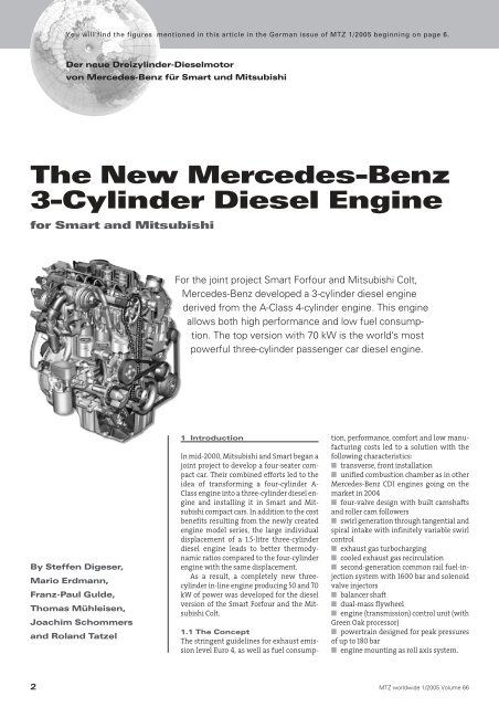
For the joint project Smart Forfour and Mitsubishi Colt,<br />
<strong>Mercedes</strong>-<strong>Benz</strong> developed a 3-cylinder diesel engine<br />
derived from the A-Class 4-cylinder engine. This engine<br />
allows both high performance and low fuel consumption.<br />
<strong>The</strong> top version with 70 kW is the world’s most<br />
powerful three-cylinder passenger car diesel engine.<br />
1 Introduction<br />
In mid-2000, Mitsubishi and Smart began a<br />
joint project to develop a four-seater compact<br />
car. <strong>The</strong>ir combined efforts led to the<br />
idea of transforming a four-cylinder A-<br />
Class engine into a three-cylinder diesel engine<br />
and installing it in Smart and Mitsubishi<br />
compact cars. In addition to the cost<br />
benefits resulting from the newly created<br />
engine model series, the large individual<br />
displacement of a 1.5-litre three-cylinder<br />
diesel engine leads to better thermodynamic<br />
ratios compared to the four-cylinder<br />
engine with the same displacement.<br />
As a result, a completely new threecylinder<br />
in-line engine producing 50 and 70<br />
kW of power was developed for the diesel<br />
version of the Smart Forfour and the Mitsubishi<br />
Colt.<br />
1.1 <strong>The</strong> Concept<br />
<strong>The</strong> stringent guidelines for exhaust emission<br />
level Euro 4, as well as fuel consump-<br />
tion, performance, comfort and low manufacturing<br />
costs led to a solution with the<br />
following characteristics:<br />
■ transverse, front installation<br />
■ unified combustion chamber as in other<br />
<strong>Mercedes</strong>-<strong>Benz</strong> CDI engines going on the<br />
market in 2004<br />
■ four-valve design with built camshafts<br />
and roller cam followers<br />
■ swirl generation through tangential and<br />
spiral intake with infinitely variable swirl<br />
control<br />
■ exhaust gas turbocharging<br />
■ cooled exhaust gas recirculation<br />
■ second-generation common rail fuel-injection<br />
system with 1600 bar and solenoid<br />
valve injectors<br />
■ balancer shaft<br />
■ dual-mass flywheel<br />
■ engine (transmission) control unit (with<br />
Green Oak processor)<br />
■ powertrain designed for peak pressures<br />
of up to 180 bar<br />
■ engine mounting as roll axis system.<br />
2 MTZ worldwide 1/2005 Volume 66
1.2 Key Data<br />
<strong>The</strong> most important technical data are<br />
compiled in the Table.<br />
2 <strong>Engine</strong><br />
2.1 Longitudinal Section and<br />
Cross-Section<br />
When designing the engine layout in the<br />
vehicle, our objective was to make the engine<br />
as compatible as possible with the<br />
petrol (gasoline) engine. At the same time,<br />
we wanted to maintain the production network<br />
with the A-Class four-cylinder diesel<br />
engine. As a result, the petrol and diesel engine<br />
designs differ with regard to the position<br />
of the intake and exhaust sides. This is<br />
primarily due to the cylinder head design.<br />
<strong>The</strong> resulting exhaust ducts as well as the<br />
compact overall height requirement led to<br />
connecting the balancer shaft on the side of<br />
the crankcase. <strong>The</strong> shaft is driven via a joint<br />
chain leading to the oil pump.<br />
Figure 1 shows the structural design of<br />
the OM 639.<br />
2.2 Crankcase<br />
<strong>The</strong> crankcase was designed as a closed<br />
deck and is made of cast iron 26 Cr. A land<br />
width of only 7 mm results from the 90 mm<br />
cylinder spacing and an 83 mm bore,<br />
through which two land coolant bores pass.<br />
<strong>The</strong> water pump body and an exhaust<br />
return duct are integrated. <strong>The</strong> flange was<br />
adapted to the transmission shared with<br />
the petrol engine. In contrast to conventional<br />
in-line engines, the starter is located<br />
on the transmission side.<br />
2.3 Powertrain<br />
<strong>The</strong> A-Class four-cylinder diesel engine production<br />
network determined such key dimensions<br />
as the 92 mm stroke and the 90<br />
mm cylinder spacing. <strong>The</strong> crankshafts are<br />
lightweight forgings made of 38 Mn S6 BY<br />
with rolled radii, hardened working surfaces<br />
and four counterweights. <strong>The</strong> pistons,<br />
rings, rods and plain bearing powertrain<br />
components that are identical to the fourcylinder<br />
diesel engine have been described<br />
in detail in the MTZ article 12/04.<br />
Throughout the development process,<br />
one of the objectives was to maintain low<br />
lubricating oil consumption even after long<br />
service lives, Figure 2. Employing a 2 mm<br />
high ventilated spring-loaded oil ring with<br />
tapered mini-lands in the third piston ring<br />
groove proved to be the decisive solution.<br />
At the same time, the flow through the oil<br />
injection nozzles was reduced and the<br />
crankcase was locally re<strong>info</strong>rced in order to<br />
reduce deformation of the cylinder bores.<br />
Moreover, the flow through the oil injection<br />
nozzles was reduced.<br />
MTZ worldwide 1/2005 Volume 66<br />
COVER STORY 3-<strong>Cylinder</strong> <strong>Diesel</strong> <strong>Engine</strong><br />
<strong>The</strong> post-bonded torsional vibration<br />
damper on the crankshaft, which holds the<br />
five-groove belt, is designed for a frequency<br />
of 495-550 Hz.<br />
A dual-mass flywheel (DMFW) was developed<br />
to improve ride comfort. <strong>The</strong> dualmass<br />
flywheel is equipped with an external<br />
damper with bow springs and a three-stage<br />
internal damper. It almost completely filters<br />
out the torsional vibrations that are<br />
above the natural frequency. Consequently,<br />
the vibrations in the transmission and<br />
the powertrain that occur above the engine<br />
idling speed are reduced to a minimum.<br />
This prevents rattling noises in the transmission<br />
during idling or while driving. Because<br />
the torsional excitation on the powertrain<br />
is reduced, noise interference and<br />
vibrations do not develop at low engine<br />
speeds of up to approximately 2000 rpm.<br />
2.4 Three-<strong>Cylinder</strong> <strong>Diesel</strong> <strong>Engine</strong><br />
Mass Balancer System<br />
A mass balancer offsets troublesome free<br />
inertial forces of the first order developing<br />
in three-cylinder engines. It sharply reduces<br />
noise emission and prevents vibrations<br />
and, therefore, contributes to a distinct<br />
improvement in ride comfort.<br />
<strong>The</strong> balancer shaft is designed as a compact<br />
module and is bolted to the side of the<br />
crankcase.<br />
<strong>The</strong> shaft is driven by the oil pump chain<br />
via a gear with a 1:1 gear ratio. A gear in the<br />
chain drive is integrated in order to reverse<br />
the rotation between the crankshaft and<br />
the balancer shaft. A rubber coating on the<br />
crankshaft gear was chosen to improve the<br />
acoustics. Figure 3 shows the complete<br />
chain drive.<br />
<strong>The</strong> balancer shaft is mounted using<br />
bearing bushings with a centre oil groove.<br />
Oil ducts that are fed directly out of the<br />
main oil duct of the crankcase supply the oil.<br />
At the same time, the balancer shaft casing<br />
holds the oil filter and the oil/water<br />
heat exchanger.<br />
As a result of extensive FEM calculations<br />
and external tests, an optimum compromise<br />
was found between rigidity (positive<br />
effect on noise and vibrations), strength<br />
and weight for the mass balancer system.<br />
2.5 <strong>Cylinder</strong> Head and Valve Gear<br />
In addition to the crank assembly and the<br />
crankcase, the cylinder head is the most important<br />
component in the production network<br />
for the four-cylinder engine of the A-<br />
Class. <strong>The</strong> crossflow concept, duct geometry,<br />
oil circuit and control system are identical.<br />
A new feature is the integration of the<br />
camshaft bearing covers into the cylinder<br />
head cover. This results in advantages for<br />
the height of the engine.<br />
<strong>The</strong> high peak pressure of 180 bar required<br />
an optimised sealing concept. A<br />
four-layer cylinder head gasket and high<br />
bolting forces ensured the desired positive<br />
results.<br />
<strong>The</strong> timing chain and the balancer<br />
shaft/oil pump chain have been designed<br />
as single-bush chains. Particularly the design<br />
of the highly stressed chain drive for<br />
the balancer shaft and the oil pump required<br />
detailed analysis and investigation,<br />
e.g. torsional vibration measurements. Precision-blanked<br />
lugs are used to minimize<br />
wear on the guide rails. A non-return valve<br />
in the chain tensioner limits the movement<br />
of the tensioning rail and thus reduces the<br />
dynamic loads on the chain drive.<br />
Both are composite camshafts and are<br />
manufactured using hydroforming.<br />
<strong>The</strong> exhaust camshaft drives the vacuum<br />
pump while the intake camshaft drives<br />
the common rail high-pressure pump. <strong>The</strong><br />
valves are actuated by the roller cam follower<br />
with vertical hydraulic valve play<br />
compensation.<br />
2.6 Oil Circuit<br />
In order to reduce the friction losses, the oil<br />
pump was optimised and the gear width<br />
was designed to 18 mm. Moreover, oil<br />
foaming is minimized by a chain wheel<br />
cover at the oil pump chain sprocket and an<br />
oil deflector under the crankshaft.<br />
<strong>The</strong> oil/water heat exchanger limits the<br />
maximum oil temperature to 135 °C.<br />
<strong>The</strong> service interval is variable and is<br />
calculated depending on the driving style<br />
and the oil brand used.<br />
Intervals of between 25,000 and 31,000<br />
km are achieved when low-viscosity oil according<br />
to DaimlerChrysler specification<br />
229.5 is used.<br />
2.7 Auxiliary Units<br />
<strong>The</strong> auxiliary unit drive is designed as a single<br />
belt drive. A five-groove belt made of<br />
EPDM and a mechanical belt take-up is<br />
used. <strong>The</strong> automatically tensioned belt tensioner<br />
has tapered bearings and is<br />
equipped with a synthetic friction lining.<br />
An air-cooled 120 A generator with a freewheel<br />
pulley and a type 5SEU9 A/C compressor<br />
are integrated as auxiliary units.<br />
<strong>The</strong> belt drive without refrigerant compressor<br />
uses a guide pulley at this point,<br />
with the result that only one belt length is<br />
necessary because of the uniform belt layout.<br />
2.8 Charge Exchange and<br />
Exhaust Gas Recirculation<br />
Figure 4 shows the layout of the gas-carrying<br />
components. <strong>The</strong> outside air flows<br />
through the intake pipe to the vehicle’s air<br />
3
COVER STORY 3-<strong>Cylinder</strong> <strong>Diesel</strong> <strong>Engine</strong><br />
filter and is measured by a hot-film airmass<br />
meter (HFM) upon exiting. <strong>The</strong> wastegate<br />
turbocharger compresses the air to a<br />
maximum pressure of 1.3 bar. A heat exchanger<br />
located in front of the left wheel<br />
arch cools the boost air. This increases the<br />
air density by 21 %.<br />
<strong>The</strong> necessary high exhaust return volumes<br />
(up to 40 %) require the relevant scavenging<br />
gradient between the exhaust return<br />
tract and the compressed fresh air<br />
tract. As a result of numerous series of tests<br />
conducted to optimise flow conditions, it<br />
was possible to keep the pressure losses<br />
that occur over the entire return track so<br />
low that there was no need for an additional<br />
throttle valve to generate a pressure differential.<br />
<strong>The</strong> exhaust heat exchanger has a cooling<br />
matrix with six rectangular pipes and<br />
impressed “winglets”. <strong>The</strong> turbulent gas<br />
flow generated by this has a self-cleaning<br />
effect on the internal pipes and positively<br />
influences the cooling capacity (DT exhaust<br />
temperature = 180 K), which does not exceed<br />
a power loss of 8 % throughout the<br />
component’s service life.<br />
<strong>The</strong> pneumatic EGR valve found in the<br />
mixing chamber directly upstream of the<br />
collecting section was designed as a bevelled<br />
poppet valve in order to further improve<br />
the regulating conditions for small<br />
strokes.<br />
<strong>The</strong> exhaust gas enters the mixing<br />
chamber centrally through an intake pipe<br />
with slots on its sides in order to optimally<br />
supply the exhaust gas with fresh air.<br />
2.9 Ventilation System<br />
A multistage separator directly mounted to<br />
the cylinder head cover separates the oil<br />
from the blow-by gases. It is made up of a<br />
smoothing volume with spiral separation,<br />
a flow separator to protect the HFM and an<br />
integrated pressure-reducing valve. <strong>The</strong><br />
separated oil flows back into the oil pan<br />
through the oil level gauge guide pipe via a<br />
freeze-proof hose. <strong>The</strong> ventilation gas flows<br />
through a cooling water-heated tube into<br />
the intake manifold in front of the turbocharger.<br />
3 Fuel-Injection System<br />
<strong>The</strong> configuration of the fuel-injection system<br />
used in the three- and four-cylinder<br />
diesel engines is consistent in its design<br />
with the proven common rail fuel-injection<br />
system in second-generation <strong>Mercedes</strong>-<br />
<strong>Benz</strong> CDI engines (MTZ 4/2002).For the second<br />
generation, the injection pressure was<br />
raised from 1350 bar to 1600 bar. Due to the<br />
special design of the A-Class engine, the<br />
overall length of the injector had to be<br />
shortened. For the first time, Daimler-<br />
Chrysler integrated a gear drive to run the<br />
flow rate-controlled high-pressure pump.<br />
In order to fulfil the stringent Euro 4<br />
specifications, including good combustion<br />
acoustics and without the need for active<br />
aftertreatment, DaimlerChrysler worked<br />
very closely with Bosch to increase the minimum<br />
volume capability in comparison<br />
with the 1600 bar EU3 solenoid fuel injector<br />
known to date, Figure 5. This was achieved<br />
by reducing the solenoid valve armature<br />
stroke and also by optimising the cross-section<br />
of the control room input and output<br />
throttle.<br />
<strong>The</strong> reduced hydraulic flow rate of the<br />
mini blind-hole nozzle and the flow-optimised<br />
spray orifice (KS geometry) excels in<br />
its improved injection preparation.<br />
<strong>The</strong> long-term stability of the fuel injector<br />
was improved by applying a carbon<br />
coating in the area of the nozzle seat, which<br />
in conjunction with the optimised solenoid<br />
group results in consistent fuel-quantity<br />
performance over time.<br />
<strong>The</strong> injector fuel-quantity compensation<br />
guarantees that the target injection quantity<br />
is maintained precisely as manufactured.<br />
<strong>The</strong> self-adapting zero fuel quantity calibration<br />
ensures that the small injection<br />
quantities are controlled over the engine’s<br />
lifetime.<br />
In order to generate multiple injections<br />
for “soft” combustion depending on the operating<br />
range, the pressure waves triggered<br />
by the preceding injection and the quantity<br />
changes associated with it are corrected by<br />
a pressure-wave correction.<br />
4 Combustion<br />
From a customer’s perspective, a modern<br />
diesel engine must exhibit high torque and<br />
power performance on the one hand, and<br />
low noise emission and fuel consumption<br />
on the other.<br />
Meeting all the specifications regarding<br />
bulk volume, Euro 4 emission levels and<br />
target costs in addition to customer needs<br />
required a fundamental redevelopment of<br />
the combustion process and the engine application.<br />
<strong>The</strong> basic principles were derived in conjunction<br />
with the newly developed OM 640<br />
four-cylinder engine for the new A-Class.<br />
Using the 1500 cc displacement of the<br />
derived OM 639 three-cylinder engine, the<br />
50 and 70 kW power variants were designed<br />
with an equivalent wastegate turbocharger.<br />
This makes the top version with<br />
70 kW the world’s most powerful threecylinder<br />
passenger car diesel engine. During<br />
the development phase, the air com-<br />
pressor efficiency and the turbine response<br />
were extensively optimised. In conjunction<br />
with the optimum-flow single-piece exhaust<br />
manifold turbine casing, this technology<br />
achieved high medium pressures,<br />
both steady-state and transient in the lower<br />
engine speed range. <strong>The</strong> maximum<br />
torque of 210 Nm in the top version is available<br />
over a wide range from 1800 to 2800<br />
rpm, Figure 6.<br />
<strong>The</strong> turbocharger is controlled by a<br />
pneumatic actuator.<br />
<strong>The</strong> air-to-air charge-air cooler is located<br />
in the vehicle’s wheel arch. <strong>The</strong> high air<br />
compressor-dependent charge-air temperatures<br />
caused by the high boost ratio of 2.3 in<br />
the top version are reduced by over 75 K.<br />
<strong>The</strong> cooled charge air is fed into the cylinder<br />
head via an integrated mixing chamber<br />
with the introduction of recirculated exhaust<br />
gas and a low-volume air intake<br />
manifold on the cylinder head, practically<br />
without effective intake runner length.<br />
<strong>The</strong> emissions concept is based on a very<br />
low level of engine-out emissions. <strong>The</strong><br />
structural design of the combustion chamber<br />
and the duct was developed in conjunction<br />
with the four-cylinder engine for the<br />
new A-Class. <strong>The</strong> goal in this case was to reduce<br />
the conflicting objectives of specific<br />
power and emissions.<br />
Here, the focus was on the design and<br />
detailed optimisation of all parameters in<br />
the intake duct configuration, made up of<br />
tangential (permanent) and spiral ducts<br />
(can be deactivated) in order to control the<br />
swirl electrically using an infinitely variable<br />
intake duct valve.<br />
<strong>The</strong> delicate optimisation of the injection<br />
nozzle geometry was an additional focal<br />
point.<br />
In conjunction with a high combustion<br />
chamber proportion in the piston recess<br />
and an optimised recess shape, the combustion<br />
process fulfils all requirements regarding<br />
emissions, fuel consumption, power<br />
and noise.<br />
In particular, it was possible to ensure<br />
the engine’s insusceptibility and long-term<br />
stability to tolerances. Outstanding specific<br />
fuel consumption was achieved despite the<br />
high specific power and internal engine<br />
compliance with Euro 4, Figure 7.<br />
This was managed within the requirement<br />
of a favourable mean friction pressure<br />
in conjunction with an efficiency-oriented<br />
application of all combustion parameters.<br />
In order to meet the high requirements<br />
regarding NVH, dual pilot injection was applied<br />
over a wide engine map range. Information<br />
gained during the parameter tests<br />
on the engine noise test stand was implemented,<br />
taking emissions and fuel con-<br />
4 MTZ worldwide 1/2005 Volume 66
5 <strong>Engine</strong> Control Unit<br />
Figure 8: Basic structure of EPB modular design Figure 9: View of control unit<br />
sumption into account. In particular, emphasis<br />
was placed on the subjective combustion<br />
noise impression (frequency spectrum)<br />
inside the vehicle and the various vehicle<br />
applications as a basis for decisionmaking.<br />
5 <strong>Engine</strong> Control Unit<br />
A Bosch control unit designed specifically<br />
for this application is used for the OM639<br />
three-cylinder engine. In addition to the vehicle<br />
functions and the common rail injection<br />
control, the complete transmission<br />
control has been implemented in the control<br />
unit, Figure 8 and Figure 9. Most of the<br />
required sensor signals are directly obtained<br />
and processed by the control unit.<br />
<strong>The</strong> control unit directly triggers the appropriate<br />
actuators. Data exchange to the other<br />
systems used in the vehicle is achieved<br />
through the CAN and LIN communication<br />
interfaces.<br />
5.1 Hardware<br />
Additional requirements regarding dissipation<br />
of maximum thermal power of the<br />
control unit are caused by the integration<br />
of the manual transmission actuators.<br />
Through extensive evaluation and simulation<br />
for the sequence of the required<br />
current profiles of each actuator, the dimensioning<br />
of the H-bridge final stages<br />
was optimised, thus enabling integration<br />
into the Bosch EPB housing.<br />
In this housing design, the thermal power<br />
loss of the components is released directly<br />
to the environment through cooling<br />
MTZ worldwide 1/2005 Volume 66<br />
banks in the floor plate. A constant thermal<br />
dissipation over the life of the control unit<br />
is ensured by a bolted connection of the circuit<br />
board and by using a heat conducting<br />
paste.<br />
5.2 Software/Application<br />
<strong>The</strong> control unit software is based on the<br />
EDC 16 platform and is designed as a<br />
torque-driven diesel engine control.<br />
<strong>The</strong> range of engine related functions<br />
corresponds for the most part to those of<br />
the control unit for the diesel engine in the<br />
new A-Class.<br />
5.2.1 Emulation EEPROM<br />
When the vehicle is running, all sensor and<br />
actuator signals are constantly monitored.<br />
Faults found are stored with additional environment<br />
data for further diagnostic purposes.<br />
Compared to previous engine control<br />
units, data are not stored in an external, serial<br />
EEPROM, but in form of an “emulated”<br />
EEPROM. In this case, emulated means that<br />
the reference data are archived in the control<br />
unit’s flash memory. This is designed<br />
only for a small number of write cycles,<br />
thus requiring a special write strategy,<br />
which ensures that the EEPROM emulated<br />
in the flash is capable of the required number<br />
of write cycles for the entire life of the<br />
control unit.<br />
5.2.2 Synchronization<br />
without a Camshaft Sensor<br />
A special feature of the three-cylinder engine<br />
is the possibility to synchronize fuel<br />
injection and position of the crankshaft<br />
without using a camshaft sensor. As opposed<br />
to other engines, here the synchronization<br />
takes place here with the help of a<br />
“virtually” generated camshaft signal. This<br />
is detected using the irregularity of the<br />
crankshaft rotation as it develops through<br />
the compression processes in the cylinders,<br />
and it is made possible by a high-resolution<br />
rotation signal acquisition.<br />
6 Test Results<br />
At -25 °C, the OM 639 starts almost as quickly<br />
as at start temperatures above 0 °C. For<br />
example, the preglow time is only 3 s at<br />
-25 °C. Endurance runs on engine test<br />
benches amounded to a toal of 30,000<br />
hours. <strong>The</strong> vehicle endurance runs took<br />
place in part under extreme climatic conditions.<br />
A total of 1.5 million km was<br />
achieved.<br />
7 Summary<br />
<strong>The</strong> three-cylinder diesel engine designed<br />
by <strong>Mercedes</strong>-<strong>Benz</strong> meets the Euro 4 emission<br />
level and allows both high performance<br />
and low fuel consumption to be<br />
achieved. <strong>The</strong> top version with 70 kW is<br />
thus the world’s most powerful three-cylinder<br />
passenger car diesel engine. <strong>The</strong> integrated<br />
balancer shaft module and the dualmass<br />
flywheel result in a pleasantly quiet<br />
engine. ■<br />
5