Condair CP3 - Klimapro
Condair CP3 - Klimapro
Condair CP3 - Klimapro

Create successful ePaper yourself
Turn your PDF publications into a flip-book with our unique Google optimized e-Paper software.
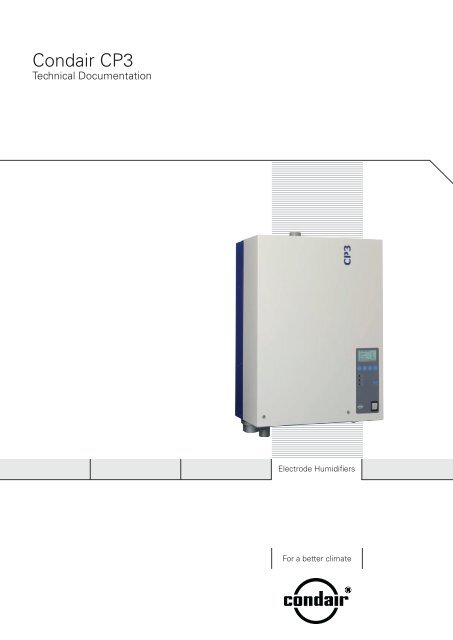
<strong>Condair</strong> <strong>CP3</strong><br />
Technical Documentation<br />
Electrode Humidifiers<br />
For a better climate
2 For your safety<br />
General<br />
Every person working with the <strong>Condair</strong> <strong>CP3</strong> must have read and understood the Technical Documentation<br />
before carrying out any work.<br />
Knowing and understanding the contents of the Technical Documentation is a basic requirement for<br />
protecting the personnel against any kind of danger, to prevent faulty operation, and to operate the<br />
unit safely and correctly.<br />
All ideograms, signs and markings applied to the unit must be observed and kept in readable<br />
state.<br />
Qualification of personnel<br />
All actions described in the present Technical Documentation (installation, operation, maintenance,<br />
etc.) must be carried out only by well trained and sufficiently qualified personnel authorised by<br />
the owner.<br />
For safety and warranty reasons any action beyond the scope of this manuals must be carried out<br />
only by qualified personnel authorised by Axair Ltd.<br />
It is assumed that all persons working with the <strong>Condair</strong> <strong>CP3</strong> are familiar and comply with the appropriate<br />
regulations on work safety and the prevention of accidents.<br />
Intended use<br />
The steam humidifier <strong>Condair</strong> <strong>CP3</strong> is intended exclusively for air humidification via a steam distributor<br />
or a ventilation unit approved by Axair Ltd. within the specified operating conditions<br />
(see chapter 10 “Product specifications”). Any other type of application without the express written<br />
consent of Axair Ltd. is considered as not conforming with the intended purpose and may lead to<br />
the <strong>Condair</strong> <strong>CP3</strong> becoming dangerous.<br />
Operation of the equipment in the intended manner requires that all the information in these<br />
instructions is observed (in particular the safety instructions).
10<br />
3.3 Steam humidifier construction<br />
12<br />
13<br />
14<br />
15<br />
16<br />
17<br />
18<br />
19<br />
The illustration above shows the large unit<br />
1 Housing (small, large)<br />
2 Cable openings, top side<br />
3 Main contactor<br />
Power board<br />
Control board with <strong>CP3</strong> Card<br />
Display and control unit<br />
Relays for remote operating and error indication<br />
Operation status indicators<br />
Cable openings, bottom side<br />
10 Drain key<br />
11 Unit switch<br />
12 Steam outlet<br />
13 Water cup<br />
20<br />
26<br />
25<br />
24<br />
23<br />
22<br />
21<br />
1 Filling hose<br />
1 Water supply hose<br />
1 Inlet valve<br />
1 Overflow hose<br />
1 Drain connection (not visible)<br />
1 Water supply pipe<br />
20 Drain pump<br />
21 Type plate<br />
22 Data plate <strong>CP3</strong> Card<br />
23 Steam cylinder<br />
2 Level sensor<br />
2 Auxiliary drain hose<br />
2 Electrode plug<br />
1<br />
2<br />
3<br />
4<br />
5<br />
6<br />
7<br />
8<br />
9<br />
10<br />
11
3.5 Functional description<br />
The steam humidifier <strong>Condair</strong> <strong>CP3</strong> is a pressureless steam generator that utilizes an electrode<br />
heating. The steam humidifier <strong>Condair</strong> <strong>CP3</strong> is designed for air humidification via a steam distributor<br />
(steam distribution pipe or steam distribution system OptiSorp).<br />
Steam generation<br />
Any time steam is requested, the electrodes are supplied with voltage via main contactor. Simultaneously,<br />
the inlet valve opens and water enters the steam cylinder from the bottom via water cup<br />
and supply line. As soon as the electrodes come in contact with the water, current begins to flow<br />
between the electrodes, eventually heating and evaporating the water. The more the electrode surface<br />
is exposed to water, the higher is the current consumption and thus the steam capacity.<br />
Upon reaching the requested steam capacity, the inlet valve closes. If the steam generation decreases<br />
below a certain percentage of the required capacity, due to lowering of the water level (e.g.<br />
because of the evaporation process or drainage), the inlet valve opens until the required capacity is<br />
available again.<br />
If the required steam capacity is lower than the actual output, the inlet valve is closed until the desired<br />
capacity is achieved by lowering of the water level (evaporation process).<br />
Level monitoring<br />
A sensor provided in the steam cylinder cover detects when the water level gets too high. The moment<br />
the sensor comes in contact with water, the inlet valve closes.<br />
Drainage<br />
As a result of the evaporation process, the conductivity of the water increases due to an escalating<br />
mineral concentration. Eventually, an inadmissibly high current consumption would take place if this<br />
concentration process were permitted to continue. To prevent this concentration from reaching a<br />
value, unsuitably high for the operation, a certain amount of water is periodically drained from the<br />
cylinder and replaced by fresh water.<br />
Control<br />
The steam production can be controlled steplessly via the internal or an external continuous controller<br />
or with an On/Off control via an external humidistat.<br />
11
12<br />
3.6 Humidification system overview<br />
1 Steam humidifier<br />
2 Steam connection<br />
3 Water drain connection<br />
Water supply connection<br />
Manometer (installation recommended)<br />
Filter valve (accessory “Z2 1”)<br />
Funnel with siphon (building side)<br />
Water drain hose (accessory “DS 0”<br />
Control voltage supply<br />
14 12<br />
KS10 13<br />
DS22<br />
DS60<br />
DS80<br />
6<br />
Z261<br />
125...1250 µS/cm<br />
1...10 bar<br />
1...40 °C<br />
5<br />
1<br />
2<br />
3<br />
4<br />
8<br />
DS60<br />
DS80<br />
DS80<br />
7<br />
15 FAN15<br />
FAN45<br />
10 Heating voltage supply<br />
11 Cable openings<br />
12 Steam hose<br />
(accessory “DS22”/“DS 0”/“DS 0”)<br />
13 Condensate hose (accessory “KS10”)<br />
1 Steam distribution pipe<br />
(accessory “ 1-..”/“ 1-..”)<br />
1 Ventilation unit<br />
(accessory accessory “FAN1 “FAN1 ”/“FAN ”/“FAN ”)<br />
”)<br />
10<br />
9<br />
11
1<br />
3.8 Options<br />
3.8.1 Options overview<br />
D... Cleanable steam cylinder<br />
Cleanable steam cylinder as an alternative<br />
to the disposable steam cylinder built in as<br />
standard (see also chapter 3.8.2).<br />
RFI Remote operating and fault indication<br />
PCB with relay contacts for the connection<br />
of remote displays for “Operation”,<br />
“Steam”, “Fault” and “Service”.<br />
OPS Overpressure kit<br />
Kit for mounting the water cup to the unit<br />
cover when operating the steam humidifiers<br />
in systems with a duct air pressure of up<br />
to 3 kPa.<br />
THV Connection terminal for heating voltage<br />
Separate terminals for systems where direct<br />
connection of heating voltage to main contactor<br />
(standard version) is not permitted by local<br />
regulations.<br />
230V1 5...8<br />
<strong>Condair</strong> <strong>CP3</strong> Basic... / <strong>Condair</strong> <strong>CP3</strong> Pro...<br />
400V3 5...8 9...15 16...45 52/60/70/80/90 105/120/135 152/160/180<br />
220V3 5...8 9...15 16...30 44/50/60 75/90 120<br />
P/B 1x D3.. 1xD4.. D6.. D6.. D6.. D6..<br />
B ** 1x RFI 1x RFI 1x RFI 1x RFI 1x RFI 1x RFI<br />
P/B 1x OPS 1x OPS 1x OPS 2x OPS 3x OPS 4x OPS<br />
B ** 1x M-THV 1x M-THV 1x L-THV 2x L-THV 3x L-THV 4x L-THV<br />
PG Cable gland B** 1 x PG 1 x PG 1x PG 2 x PG 3 x PG 4 x PG<br />
INOX Unit housing of stainless steel P/B 1x M-INOX 1x M-INOX 1x L-INOX 2x L-INOX 3x L-INOX 4x L-INOX<br />
TMP Ventilator for ambient temperatures up<br />
to 50 °C<br />
P/B 1x TMP 1x TMP 1x TMP 2x TMP 3x TMP 4x TMP<br />
SC.. Steam connector B ** 1x SC22 1x SC60 1x SC80 2x SC80 3x SC80 4x SC80<br />
SCCT.. Steam connector with condensate trap B 1x SCCT22 1x SCCT60 1x SCCT80 2x SCCT80 3x SCCT80 4x SCCT80<br />
CT Condensate trap P/B 1x CT 1x CT 1x CT 2x CT 3x CT 4x CT<br />
MP Mounting profile 1x M-MP 1x M-MP 1x L-MP 2x L-MP 3x L-MP 4x L-MP<br />
CVI Internal contgrol voltage P/B 1x M-CVI 1x M-CVI 1x L-CVI 1x L-CVI 2x L-CVI 2x L-CVI<br />
TRAFO Transformner (400V/230V) P/B 1x M-Trafo 1x M-Trafo 1x L-Trafo 2x L-Trafo 3x L-Trafo 4x L-Trafo<br />
B Unit version Basic<br />
P Unit version Pro<br />
** Standard for unit version Pro
1<br />
3.9 Accessories<br />
3.9.1 Accessories overview<br />
Accessories for water installation<br />
230V1 5...8<br />
<strong>Condair</strong> <strong>CP3</strong> Basic... / <strong>Condair</strong> <strong>CP3</strong> Pro...<br />
400V3 5...8 9...15 16...45 52/60/70/80/90 105/120/135 152/160/180<br />
220V3 5...8 9...15 16...30 44/50/60 75/90 120<br />
Filter valve Z261 (1 1 pcs. per system)<br />
Accessories for steam installation<br />
Steam distribution pipe<br />
(Details see chapter 3.9.2)<br />
Steam distribution system OptiSorp<br />
(Details see chapter 3.9.2)<br />
Fan unit<br />
(Details see chapter 3.9.2)<br />
230V1 5...8<br />
<strong>Condair</strong> <strong>CP3</strong> Basic... / <strong>Condair</strong> <strong>CP3</strong> Pro...<br />
400V3 5...8 9...15 16...45 52/60/70/80/90 105/120/135 152/160/180<br />
220V3 5...8 9...15 16...30 44/50/60 75/90 120<br />
1x 41-... 1x 61-... 1x 81-... 2x 81-... 3x 81-... 4x 81-...<br />
––– System 1 System 2 System 3 System 4<br />
1x FAN15 1x FAN45 2x FAN45 3x FAN45 4x FAN45<br />
Steam hose / meter 1x DS22 1x DS60 1x DS80 2x DS80 3x DS80 4x DS80<br />
Condensate hose / meter 1x KS10 2x KS10 3x KS10 4x KS10<br />
Accessories for humidity control<br />
230V1 5...8<br />
<strong>Condair</strong> <strong>CP3</strong> Basic... / <strong>Condair</strong> <strong>CP3</strong> Pro...<br />
400V3 5...8 9...15 16...45 52/60/70/80/90 105/120/135 152/160/180<br />
220V3 5...8 9...15 16...30 44/50/60 75/90 120<br />
Humidity sensor for duct installation EGH110 (1 1 pcs. per system)<br />
Humidity sensor for room installation EGH130 (1 1 pcs. per system)<br />
Duct humidistat HBC (1 1 pcs. per system)<br />
Room humidistat HSC (1 1 pcs. per system)
5.2 Installation overview<br />
Pmax 1500 Pa<br />
Pmin -800 Pa<br />
Pmax 1500 Pa<br />
Pmin -800 Pa<br />
41-...<br />
61-...<br />
81-...<br />
min. 20 %<br />
–<br />
Steam installation,<br />
see chapter .<br />
41-...<br />
61-...<br />
81-...<br />
KS10<br />
Ømin. 200 mm<br />
min. 20 %<br />
–<br />
KS10<br />
Rmin. 300 mm<br />
125...1250 µS/cm<br />
1...10 bar<br />
1...40 °C<br />
Water installation,<br />
see chapter .<br />
Ømin. 200 mm<br />
230V/1~/50Hz<br />
max. 4 m<br />
min. 5 % –<br />
min. 5 % –<br />
60...70 °C<br />
ø40 mm<br />
R 3/4"<br />
R 1/2"<br />
max. 4 m<br />
ø10/8 mm<br />
Z261<br />
≥ 40 mm<br />
Rmin. 300 mm<br />
DS80<br />
min. 20 %<br />
+<br />
min. 50 cm<br />
DS22<br />
DS60<br />
DS80<br />
min. 10 % –<br />
DS60<br />
DS80<br />
1 ... 40 °C<br />
max. 75 %rF<br />
IP20<br />
min. 10 % –<br />
min. 300 mm<br />
Mounting the unit,<br />
see chapter .3<br />
400V/3~/50Hz<br />
230V/1~/50Hz<br />
Electric installation,<br />
see chapter .<br />
2
5.6 Electric installation<br />
5.6.1 Wiring diagram<br />
CPU BOARD DRIVER BOARD A<br />
DRIVER BOARD B<br />
X2 X7 X4 X3<br />
SWITCH VTX SUPPLY INLET V. DRAIN V. CONTACTOR<br />
LEV. SENSOR<br />
X5<br />
J2<br />
LINK UP<br />
J4<br />
EXTERNAL CON.<br />
J1<br />
CPU BOARD<br />
F2<br />
200mAF<br />
JP3<br />
J3<br />
DRIVER B<br />
OUT 24V<br />
OUT 5V<br />
F1 6.3 AT<br />
X1<br />
MAIN SUPPLY<br />
PE L1 N SC1SC2<br />
X6<br />
Modul B<br />
P N P1<br />
J2<br />
FAULT REMOTE<br />
X2 X7 X4 X3<br />
SWITCH VTX SUPPLY INLET V. DRAIN V. CONTACTOR<br />
LEV. SENSOR<br />
X5<br />
J2<br />
LINK UP<br />
J4<br />
EXTERNAL CON.<br />
J1<br />
CPU BOARD<br />
F2<br />
200mAF<br />
JP3<br />
OUT 24V<br />
OUT 5V<br />
BLOWER<br />
V+ IN<br />
LIM. SIGN<br />
INGND<br />
CONT.SIGN<br />
V+ INGND<br />
F1 6.3 AT<br />
X1<br />
MAIN SUPPLY<br />
PE L1 N SC1SC2<br />
X6<br />
Modul B<br />
P N P1<br />
J4<br />
BLOWER<br />
V+ IN<br />
LIM. SIGN<br />
INGND<br />
CONT.SIGN<br />
V+ INGND<br />
J1 DRIVER A<br />
J<br />
+ – + –<br />
A1 A4<br />
Q4<br />
P / PI<br />
P / PI<br />
Fault Remote Board<br />
H1<br />
F4<br />
Heating Module A<br />
GND<br />
V+ IN<br />
Sensor Supply<br />
Max. 60mA<br />
Heating Module B<br />
B3<br />
ϕ<br />
max.<br />
L1 N<br />
230 V/1N~/50..60 Hz<br />
4 3 2 1 2 1<br />
L1 L1 L2 L3<br />
K1<br />
Set JP OUT<br />
to 5 V<br />
A2<br />
140Ω...10kΩ<br />
Unit ON<br />
Analog Out<br />
∆p<br />
GND<br />
V+ IN<br />
Steam<br />
F1<br />
100mA<br />
L1 L2 L3<br />
X0<br />
Set JP OUT<br />
to 24 V<br />
Service<br />
On/Off<br />
1 2 3 4 5 6 7 8 9 10<br />
L1 L1 L2 L3<br />
K1<br />
B2<br />
B1<br />
K1<br />
A3<br />
L1 L2 L3<br />
X0<br />
Error<br />
Q3<br />
Q3<br />
F3<br />
F3<br />
L1 L2 L3 PE<br />
L1 L2 L3 PE<br />
400 V/3~/50..60 Hz<br />
400 V/3~/50..60 Hz<br />
K1 Main contactor (for connecting the heating voltage supply to the unit)<br />
Q3 External service switch heating voltage supply<br />
Q4 External service switch control voltage supply<br />
X0 Connection terminal heating voltage (unit version Pro)<br />
X1 Connection terminal control voltage<br />
X6 Connection to module B<br />
F2 Internal fuse “Driver board” control signal (200 mA, à fast acting)<br />
F3 External fuse heating voltage supply<br />
F4 External fuse control voltage supply<br />
H1 Remote operating and fault indication<br />
J Short circuited, if no external monitoring devices are connected<br />
J2 Link-up system “Driver board”<br />
JP1 Termination Link-up system<br />
K External safety chain<br />
A1 Controller (active) or humidity sensor<br />
A2 Controller (passive), set JP3 to position 5V<br />
A3 On/Off controller, set JP3 to position 24V<br />
A4 Limitation signal<br />
B1 Ventilation interlock<br />
B2 Safety humidistat<br />
B3 Airflow monitor<br />
F1 Internal fuse “Driver board” (6.3 A, slow acting)<br />
1
10 Product specifications<br />
10.1 Technical data<br />
<strong>Condair</strong> <strong>CP3</strong> ... 400V3<br />
5...15 16...45<br />
Heating voltage 00V/3~/ 0… 0Hz<br />
Steam capacity in kg/h ...1 1 ...<br />
Max. electrical power rating in kW 3. ...11.3 12.0...33.<br />
Control voltage 230V/1N~/ 0- 0Hz<br />
Admissible water pressure 1...10 bar<br />
Water quality Untreated drinking water with<br />
a conductivity from 12 to 12 0 µS/cm<br />
Admissible water temperature 1... 0 ºC<br />
Admissible ambient temperature 1... 0 ºC<br />
Admissible ambient humidity max. %rh<br />
Admissible duct air pressure –0. kPa...1. kPa,<br />
with pressure compensation kit (option) up to 3.0 kPa<br />
Protection class IP20<br />
Conformity CE<br />
Housing (BxHxT) in mm 0 x 0x2 20x 0x3<br />
Net weight 23 kg 2 kg<br />
Operating weight 0 kg kg<br />
1
2<br />
10.2 Unit dimensions<br />
<strong>Condair</strong> <strong>CP3</strong> 5...15 (dimensions in mm)<br />
177<br />
280<br />
456<br />
ø42.5<br />
150<br />
178<br />
228<br />
73<br />
93<br />
620<br />
34 40<br />
28<br />
105<br />
28<br />
71<br />
51<br />
500<br />
175 175
<strong>Condair</strong> <strong>CP3</strong> 16...45 (Dimensions in mm)<br />
177<br />
350<br />
175<br />
73<br />
34<br />
93<br />
667<br />
28<br />
105<br />
228<br />
40<br />
559<br />
ø42.5<br />
32<br />
71<br />
49<br />
545<br />
279<br />
220 220<br />
3