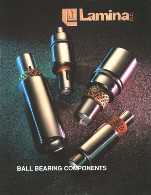
Lamina Inc. - Ball Bearing Components - Punch Tools
Lamina Inc. - Ball Bearing Components - Punch Tools
Lamina Inc. - Ball Bearing Components - Punch Tools

You also want an ePaper? Increase the reach of your titles
YUMPU automatically turns print PDFs into web optimized ePapers that Google loves.
2<br />
In component selection varied characteristics must be taken into consideration when selecting length of guide<br />
post, bushing and ball bearing retainer, such as stroke, shut height and type of operation. To help in your<br />
selection we have supplied engineering data and instructions that should be used as a guide when making your<br />
component selection. The following conditions should be considered for the most effective performance in a<br />
specific application.<br />
FULL CONTACT PRE-LOAD<br />
In this condition the guide post, bushing<br />
and ball bearing retainer remain in<br />
full contact throughout the stroke cycle.<br />
This selection is beneficial and recommended<br />
for high speed, high production,<br />
short stroke dies.<br />
We are committed to satisfying our customers by finding<br />
new and better ways to design, manufacture and<br />
distribute quality products.<br />
OPERATING DATA & DESIGN SELECTION<br />
PRE-LOAD RELIEVED AT TOP OF<br />
STROKE<br />
This may be accomplished by selecting<br />
the guide post bushing length that allows<br />
the guide post to disengage the<br />
bushing at the beginning of the stroke<br />
or cycle. This will result in the loss of<br />
pre-load while the ball retainer is still<br />
within the bushing. This condition may<br />
be utilized with long stroke dies. It also<br />
provides safe operation by eliminating<br />
pinch points and prevents foreign materials<br />
from entering the bushing. A further<br />
benefit is it allows for re-registration<br />
of the ball retainer on each stroke.<br />
Removal of the punch holder or die<br />
holder from press is possible without<br />
total removal of dies.<br />
FULL DISENGAGEMENT<br />
This condition is permisable when the<br />
ball retainer must totally disengage the<br />
bushing on applications requiring long<br />
strokes. Safety precautions (as outlined<br />
on page 5) should always be taken when<br />
employing this method.<br />
It should also be noted the the above<br />
illustration depicts the proper way to<br />
assemble (insert) the guide post and ball<br />
bearing retainer into the bushing.<br />
When in a pre-loaded (rolling press fit) condition, the<br />
ball retainer will travel half the distance of movement.<br />
In a die set application it would be half the distance<br />
of the press stroke.<br />
BALL BEARING ASSEMBLY<br />
LUBRICATION RECOMMENDATION<br />
In operation of ball assembly, add lubricant once each<br />
8-hour shift by spray or brush application. Use a<br />
lightweight spindle oil like <strong>Lamina</strong> <strong>Ball</strong> Lube.<br />
NEVER USE GREASE
Radial Placement<br />
reduces wear and<br />
tracking<br />
<strong>Lamina</strong> ball retainers (AR1) are made of a heat treated aluminum<br />
alloy that combines lightness and strength.<br />
Each retainer is quality inspected for dimensional tolerance and<br />
all burrs are removed prior to ball insertion.<br />
<strong>Ball</strong> bearings are of the highest quality AAA1 Grade (25 millionth<br />
class), continually inspected to meet our exacting tolerance.<br />
After the ball bearings have been inserted into the retainer,<br />
they are then staked using <strong>Lamina</strong>’s unique method that allows<br />
free movement with maximum security.<br />
After staking, the retainers are then scrubbed to remove all<br />
metal particles that could cause accelerated tracking and grooving<br />
in the post and bushing.<br />
<strong>Ball</strong> bearings are placed in retainers in an off-line radial pattern<br />
that offers optimum life in high or low speed presses.<br />
<strong>Ball</strong> retainers are fastened to the guide post by means of a set<br />
screw and slot in guide post and are interchangeable with all<br />
other manufacturers using this method.<br />
PRECISION BALL BEARING RETAINERS #AR1<br />
L1<br />
D1<br />
PART<br />
NUMBER<br />
D1 L1<br />
AR1-0606<br />
1.50<br />
AR1-0607 1.75<br />
AR1-0608 3/4" 2.00<br />
AR1-0609 2.25<br />
AR1-0610 *2.50<br />
AR1-0806<br />
1.50<br />
AR1-0807 1.75<br />
AR1-0808 1"<br />
2.00<br />
AR1-0809 2.25<br />
AR1-0810 *2.50<br />
AR1-1008<br />
2.00<br />
AR1-1009 2.25<br />
AR1-1010<br />
AR1-1011<br />
1-1/4"<br />
2.50<br />
2.75<br />
AR1-1012 3.00<br />
AR1-1013 *3.25<br />
AR1-1210<br />
2.50<br />
AR1-1211 2.75<br />
AR1-1212<br />
AR1-1213<br />
1-1/2"<br />
3.00<br />
3.25<br />
AR1-1214 3.50<br />
AR1-1215 *3.75<br />
AR1-1411<br />
2.75<br />
AR1-1412 3.00<br />
AR1-1413 3.25<br />
AR1-1414 1-3/4" 3.50<br />
AR1-1415 3.75<br />
AR1-1416 4.00<br />
AR1-1417 *4.25<br />
AR1-1613<br />
3.25<br />
AR1-1614 3.50<br />
AR1-1615<br />
AR1-1616<br />
2<br />
3.75<br />
4.00<br />
AR1-1617 4.25<br />
AR1-1618 *4.50<br />
AR1-2020<br />
5.00<br />
AR1-2022 5.50<br />
AR1-2024 2-1/2 6.00<br />
AR1-2026 6.50<br />
AR1-2028 *7.00<br />
AR1-2420<br />
5.00<br />
AR1-2424 3<br />
6.00<br />
AR1-2428 *7.00<br />
An asterisk (*) designates that the retainer<br />
length is recommended for general<br />
die set applications. Lengths not<br />
marked with an asterisk are for limited<br />
space use and special applications.<br />
3
4<br />
Note: Straight sleeve bushings are 1/8” shorter than nominal.<br />
PART<br />
NUMBER<br />
AB1-0607<br />
AB1-0608<br />
AB1-0609<br />
AB1-0610<br />
AB1-0611<br />
AB1-0612<br />
AB1-0613<br />
AB1-0614<br />
AB1-0615<br />
AB1-0616<br />
AB1-0618<br />
AB1-0620<br />
AB1-0624<br />
AB1-0808<br />
AB1-0809<br />
AB1-0810<br />
AB1-0811<br />
AB1-0812<br />
AB1-0813<br />
AB1-0814<br />
AB1-0815<br />
AB1-0816<br />
AB1-0817<br />
AB1-0818<br />
AB1-0819<br />
AB1-0820<br />
AB1-0822<br />
AB1-0824<br />
AB1-0826<br />
AB1-0828<br />
AB1-1010<br />
AB1-1011<br />
AB1-1012<br />
AB1-1013<br />
AB1-1014<br />
AB1-1015<br />
AB1-1016<br />
AB1-1017<br />
AB1-1018<br />
AB1-1019<br />
AB1-1020<br />
AB1-1022<br />
AB1-1024<br />
AB1-1026<br />
AB1-1028<br />
AB1-1032<br />
AB1-1036<br />
NOM PIN<br />
DIA<br />
D1 D2 L1<br />
3/4" 1.1258 1.387<br />
1" 1.3768 1.717<br />
1-1/4" 1.6265 2.107<br />
1.75<br />
2.00<br />
2.25<br />
2.50<br />
2.75<br />
3.00<br />
3.25<br />
3.50<br />
3.75<br />
4.00<br />
4.50<br />
5.00<br />
6.00<br />
2.00<br />
2.25<br />
2.50<br />
2.75<br />
3.00<br />
3.25<br />
3.50<br />
3.75<br />
4.00<br />
4.25<br />
4.50<br />
4.75<br />
5.00<br />
5.50<br />
6.00<br />
6.50<br />
7.00<br />
2.50<br />
2.75<br />
3.00<br />
3.25<br />
3.50<br />
3.75<br />
4.00<br />
4.25<br />
4.50<br />
4.75<br />
5.00<br />
5.50<br />
6.00<br />
6.50<br />
7.00<br />
8.00<br />
9.00<br />
L1<br />
PART<br />
NUMBER<br />
AB1-1212<br />
AB1-1213<br />
AB1-1214<br />
AB1-1215<br />
AB1-1216<br />
AB1-1217<br />
AB1-1218<br />
AB1-1219<br />
AB1-1220<br />
AB1-1221<br />
AB1-1222<br />
AB1-1224<br />
AB1-1226<br />
AB1-1228<br />
AB1-1230<br />
AB1-1232<br />
AB1-1234<br />
AB1-1236<br />
AB1-1240<br />
AB1-1242<br />
AB1-1244<br />
AB1-1248<br />
AB1-1412<br />
AB1-1414<br />
AB1-1415<br />
AB1-1416<br />
AB1-1417<br />
AB1-1418<br />
AB1-1419<br />
AB1-1420<br />
AB1-1421<br />
AB1-1422<br />
AB1-1424<br />
AB1-1426<br />
AB1-1428<br />
AB1-1430<br />
AB1-1432<br />
AB1-1434<br />
AB!-1436<br />
AB1-1438<br />
AB1-1440<br />
AB1-1442<br />
AB1-1444<br />
AB1-1448<br />
AB1-1452<br />
D1<br />
D2<br />
NOM PIN<br />
DIA<br />
STRAIGHT SLEEVE BUSHINGS #AB1<br />
D1 D2 L1<br />
1-1/2" 1.8765 2.437<br />
1-3/4" 2.1265 2.747<br />
<strong>Lamina</strong>’s <strong>Ball</strong> <strong>Bearing</strong> Guide Assembly Bushings<br />
(AB1) are made from vacuum degassed chrome alloy<br />
steel, hardened to precise Rockwell limits to give<br />
minimum tracking, grooving and downtime.<br />
<strong>Lamina</strong>’s ball bushings are ground and honed to<br />
exacting tolerance limits. Using high tech electronic<br />
and air checking instruments on I.D. and O.D. make<br />
them interchangeable and do not require select fitting.<br />
The top is chamferred on I.D. to minimize wear and<br />
aid alignment when disengagement is required.<br />
To minimize bushing close-in which is a result of<br />
press fit and to eliminate any additional grinding or<br />
honing, boring instructions are provided in this catalog.<br />
3.00<br />
3.25<br />
3.50<br />
3.75<br />
4.00<br />
4.25<br />
4.50<br />
4.75<br />
5.00<br />
5.25<br />
5.50<br />
6.00<br />
6.50<br />
7.00<br />
7.50<br />
8.00<br />
8.50<br />
9.00<br />
10.00<br />
10.50<br />
11.00<br />
12.00<br />
3.00<br />
3.50<br />
3.75<br />
4.00<br />
4.25<br />
4.50<br />
4.75<br />
5.00<br />
5.25<br />
5.50<br />
6.00<br />
6.50<br />
7.00<br />
7.50<br />
8.00<br />
8.50<br />
9.00<br />
9.50<br />
10.00<br />
10.50<br />
11.00<br />
12.00<br />
13.00<br />
PART<br />
NUMBER<br />
AB1-1612<br />
AB1-1614<br />
AB1-1615<br />
AB1-1616<br />
AB1-1617<br />
AB1-1618<br />
AB1-1619<br />
AB1-1620<br />
AB1-1621<br />
AB1-1622<br />
AB1-1624<br />
AB1-1626<br />
AB1-1628<br />
AB1-1630<br />
AB1-1632<br />
AB1-1634<br />
AB1-1636<br />
AB1-1638<br />
AB1-1640<br />
AB1-1642<br />
AB1-1644<br />
AB1-1648<br />
AB1-1652<br />
AB1-1656<br />
AB1-2024<br />
AB1-2026<br />
AB1-2028<br />
AB1-2030<br />
AB1-2032<br />
AB1-2034<br />
AB1-2036<br />
AB1-2038<br />
AB1-2040<br />
AB1-2042<br />
AB1-2044<br />
AB1-2048<br />
AB1-2052<br />
AB1-2056<br />
AB1-2424<br />
AB1-2426<br />
AB1-2428<br />
AB1-2430<br />
AB1-2432<br />
AB1-2434<br />
AB!-2436<br />
AB1-2438<br />
AB1-2440<br />
AB1-2442<br />
AB1-2444<br />
AB1-2448<br />
AB1-2452<br />
AB1-2456<br />
NOM PIN<br />
DIA<br />
D1 D2 L1<br />
2" 2.5015 3.162<br />
2-1/2" 3.0015 3.682<br />
3" 3.5015 4.182<br />
3.00<br />
3.50<br />
3.75<br />
4.00<br />
4.25<br />
4.50<br />
4.75<br />
5.00<br />
5.25<br />
5.50<br />
6.00<br />
6.50<br />
7.00<br />
7.50<br />
8.00<br />
8.50<br />
9.00<br />
9.50<br />
10.00<br />
10.50<br />
11.00<br />
12.00<br />
13.00<br />
14.00<br />
6.00<br />
6.50<br />
7.00<br />
7.50<br />
8.00<br />
8.50<br />
9.00<br />
9.50<br />
10.00<br />
10.50<br />
11.00<br />
12.00<br />
13.00<br />
14.00<br />
6.00<br />
6.50<br />
7.00<br />
7.50<br />
8.00<br />
8.50<br />
9.00<br />
9.50<br />
10.00<br />
10.50<br />
11.00<br />
12.00<br />
13.00<br />
14.00
5 /16 - 18 S.C.H.S.<br />
N<br />
M<br />
D4<br />
D2<br />
D1<br />
D3<br />
.193<br />
L3<br />
L4<br />
L1<br />
REPLACEMENT KITS<br />
CLAMPS & SCREWS<br />
PART<br />
NUMBER<br />
# Clamps No of<br />
Nom Pin<br />
& Screws Kits<br />
Diameters<br />
per Kit Needed<br />
CSK200003 1" 3 1<br />
CSK200003 1¼" - 1½" 3 1<br />
CSK200002 1¾" - 3" 2 2<br />
Toe clamps and socket head screws are<br />
provided to hold the bushings in place.<br />
Demountable shoulder bushings offer all the<br />
advantages of straight sleeve bushings and<br />
combine them with the convenience of easy<br />
assembly and disassembly.<br />
These clamp type bushings are meant to be<br />
wring fit into the die shoe and should never<br />
be forced or inserted by hammering.<br />
ABD unground demountable bushings are<br />
available with .015 grind stock on the “D2”<br />
dimension. Specify when ordering.<br />
DEMOUNTABLE SHOULDER BUSHINGS #ABG<br />
Note: Shoulder bushings are 1/8” shorter than nominal<br />
PART<br />
NUMBER<br />
ABG0808<br />
ABG0809<br />
ABG0811<br />
ABG0812<br />
ABG0813<br />
ABG0814<br />
ABG0815<br />
ABG1010<br />
ABG1011<br />
ABG1012<br />
ABG1013<br />
ABG1014<br />
ABG1015<br />
ABG1016<br />
ABG1017<br />
ABG1018<br />
ABG1020<br />
ABG1022<br />
ABG1024<br />
ABG1212<br />
ABG1213<br />
ABG1214<br />
ABG1215<br />
ABG1216<br />
ABG1217<br />
ABG1218<br />
ABG1219<br />
ABG1220<br />
ABG1222<br />
ABG1224<br />
ABG1412<br />
ABG1414<br />
ABG1416<br />
ABG1417<br />
ABG1418<br />
ABG1419<br />
ABG1420<br />
ABG1421<br />
ABG1422<br />
ABG1424<br />
ABG1426<br />
ABG1428<br />
ABG1430<br />
ABG1612<br />
ABG1614<br />
ABG1615<br />
ABG1616<br />
ABG1617<br />
ABG1618<br />
ABG1619<br />
ABG1620<br />
ABG1621<br />
ABG1622<br />
ABG1624<br />
ABG1626<br />
ABG1628<br />
ABG1630<br />
ABG2020<br />
ABG2022<br />
ABG2024<br />
ABG2026<br />
ABG2028<br />
ABG2030<br />
ABG2420<br />
ABG2422<br />
ABG2424<br />
ABG2426<br />
ABG2428<br />
ABG2430<br />
Nom<br />
Pin Dia<br />
Inside<br />
Dia D1<br />
* When ordering unground Demountable <strong>Ball</strong><br />
<strong>Bearing</strong> Bushings please use the prefix ABD.<br />
The flange must be ground flat when grinding<br />
the D2 dimension to assure a square<br />
surface when seating the bushing.<br />
D2 D3 D4 L1 L3 L4 M N<br />
1 1.3768 1.716 1.920 1.995<br />
1-1/4 1.6265 2.106 2.280 2.355<br />
1-1/2 1.8765 2.436 2.600 2.675<br />
1-3/4 2.1265 2.746 2.920 2.995<br />
2 2.5015 3.161 3.500 3.565<br />
2-1/2 3.0015 3.681 4.000 4.075<br />
3 3.5015 4.181 4.500 4.575<br />
2.00<br />
2.25<br />
2.75<br />
3.00<br />
3.25<br />
3.50<br />
3.75<br />
2.50<br />
2.75<br />
3.00<br />
3.25<br />
3.50<br />
3.75<br />
4.00<br />
4.25<br />
4.50<br />
5.00<br />
5.50<br />
6.00<br />
3.00<br />
3.25<br />
3.50<br />
3.75<br />
4.00<br />
4.25<br />
4.50<br />
4.75<br />
5.00<br />
5.50<br />
6.00<br />
3.00<br />
3.50<br />
4.00<br />
4.25<br />
4.50<br />
4.75<br />
5.00<br />
5.25<br />
5.50<br />
6.00<br />
6.50<br />
7.00<br />
7.50<br />
3.00<br />
3.50<br />
3.75<br />
4.00<br />
4.25<br />
4.50<br />
4.75<br />
5.00<br />
5.25<br />
5.50<br />
6.00<br />
6.50<br />
7.00<br />
7.50<br />
5.00<br />
5.50<br />
6.00<br />
6.50<br />
7.00<br />
7.50<br />
5.00<br />
5.50<br />
6.00<br />
6.50<br />
7.00<br />
7.50<br />
1.125<br />
1.125<br />
1.375<br />
1.375<br />
1.375<br />
1.375<br />
1.375<br />
0.875<br />
1.125<br />
1.625<br />
1.875<br />
2.125<br />
2.375<br />
2.625<br />
1.375<br />
1.625<br />
1.875<br />
2.125<br />
2.375<br />
2.625<br />
2.875<br />
3.125<br />
3.375<br />
3.875<br />
4.375<br />
4.875<br />
1.625<br />
1.875<br />
2.125<br />
2.375<br />
2.625<br />
2.875<br />
3.125<br />
3.375<br />
3.625<br />
4.125<br />
4.625<br />
1.625<br />
2.125<br />
2.625<br />
2.875<br />
3.125<br />
3.375<br />
3.625<br />
3.875<br />
4.125<br />
4.625<br />
5.125<br />
5.625<br />
6.125<br />
1.625<br />
2.125<br />
2.375<br />
2.625<br />
2.875<br />
3.125<br />
3.375<br />
3.625<br />
3.875<br />
4.125<br />
4.625<br />
5.125<br />
5.625<br />
6.125<br />
3.625<br />
4.125<br />
4.625<br />
5.125<br />
5.625<br />
6.125<br />
3.625<br />
4.125<br />
4.625<br />
5.125<br />
5.625<br />
6.125<br />
1.218 1.594<br />
1.406 1.781<br />
1.562 1.937<br />
1.718 2.094<br />
2.000 2.375<br />
2.250 2.625<br />
2.500 2.875<br />
5
6<br />
Note: Guide posts are 1/8” shorter than nominal.<br />
PART<br />
NUMBER<br />
AP1-0612<br />
AP1-0613<br />
AP1-0614<br />
AP1-0615<br />
AP1-0616<br />
AP1-0617<br />
AP1-0618<br />
AP1-0619<br />
AP1-0620<br />
AP1-0622<br />
AP1-0624<br />
AP1-0815<br />
AP1-0816<br />
AP1-0817<br />
AP1-0818<br />
AP1-0819<br />
AP1-0820<br />
AP1-0821<br />
AP1-0822<br />
AP1-0823<br />
AP1-0824<br />
AP1-0826<br />
AP1-0828<br />
AP1-0830<br />
AP1-0832<br />
AP1-0834<br />
AP1-0836<br />
AP1-1018<br />
AP1-1019<br />
AP1-1020<br />
AP1-1021<br />
AP1-1022<br />
AP1-1023<br />
AP1-1024<br />
AP1-1026<br />
AP1-1028<br />
AP1-1030<br />
AP1-1032<br />
AP1-1034<br />
AP1-1036<br />
AP1-1040<br />
AP1-1044<br />
AP1-1048<br />
D1 L1<br />
3/4"<br />
(.753)<br />
1"<br />
(1.003)<br />
1-1/4"<br />
(1.253<br />
3.00<br />
3.25<br />
3.50<br />
3.75<br />
4.00<br />
4.25<br />
4.50<br />
4.75<br />
5.00<br />
5.50<br />
6.00<br />
3.75<br />
4.00<br />
4.25<br />
4.50<br />
4.75<br />
5.00<br />
5.25<br />
5.50<br />
5.75<br />
6.00<br />
6.50<br />
7.00<br />
7.50<br />
8.00<br />
8.50<br />
9.00<br />
4.50<br />
4.75<br />
5.00<br />
5.25<br />
5.50<br />
5.75<br />
6.00<br />
6.50<br />
7.00<br />
7.50<br />
8.00<br />
8.50<br />
9.00<br />
10.00<br />
11.00<br />
12.00<br />
L1<br />
PART<br />
NUMBER<br />
AP1-1218<br />
AP1-1219<br />
AP1-1220<br />
AP1-1221<br />
AP1-1222<br />
AP1-1223<br />
AP1-1224<br />
AP1-1226<br />
AP1-1228<br />
AP1-1230<br />
AP1-1232<br />
AP1-1234<br />
AP1-1236<br />
AP1-1238<br />
AP1-1240<br />
AP1-1242<br />
AP1-1244<br />
AP1-1246<br />
AP1-1248<br />
AP1-1250<br />
AP1-1251<br />
AP1-1256<br />
AP1-1420<br />
AP1-1421<br />
AP1-1422<br />
AP1-1423<br />
AP1-1424<br />
AP1-1425<br />
AP1-1426<br />
AP1-1428<br />
AP1-1430<br />
AP1-1432<br />
AP1-1434<br />
AP1-1436<br />
AP1-1438<br />
AP1-1440<br />
AP1-1442<br />
AP1-1444<br />
AP1-1446<br />
AP1-1448<br />
AP1-1450<br />
AP1-1452<br />
AP1-1456<br />
AP1-1460<br />
AP1-1468<br />
D1<br />
STRAIGHT GUIDE POSTS #AP1<br />
D1 L1<br />
1-1/2"<br />
(1.503)<br />
1-31/4"<br />
(1.753)<br />
<strong>Lamina</strong>’s Precision Guide Posts (AP1) for ball<br />
bearing assemblies are made from chrome alloy<br />
steel, hardened to provide maximum protection<br />
against tracking and accelerated wear.<br />
Ground to a high degree of tolerance accuracy<br />
that also provides a smooth hard wearing surface<br />
to assure free rolling of balls to maintain constant,<br />
predictable preload and complete interchangeability,<br />
not only with our own but other manufacturers’<br />
also.<br />
Boring instructions for press fit are provided in<br />
this catalog.<br />
4.50<br />
4.75<br />
5.00<br />
5.25<br />
5.50<br />
5.75<br />
6.00<br />
6.50<br />
7.00<br />
7.50<br />
8.00<br />
8.50<br />
9.00<br />
9.50<br />
10.00<br />
10.50<br />
11.00<br />
11.50<br />
12.00<br />
12.50<br />
13.00<br />
14.00<br />
5.00<br />
5.25<br />
5.50<br />
5.75<br />
6.00<br />
6.25<br />
6.50<br />
7.00<br />
7.50<br />
8.00<br />
8.50<br />
9.00<br />
9.50<br />
10.00<br />
10.50<br />
11.00<br />
11.50<br />
12.00<br />
12.50<br />
13.00<br />
14.00<br />
15.00<br />
17.00<br />
PART<br />
NUMBER<br />
AP1-1622<br />
AP1-1623<br />
AP1-1624<br />
AP1-1625<br />
AP1-1626<br />
AP1-1627<br />
AP1-1628<br />
AP1-1629<br />
AP1-1630<br />
AP1-1631<br />
AP1-1632<br />
AP1-1634<br />
AP1-1636<br />
AP1-1638<br />
AP1-1640<br />
AP1-1642<br />
AP1-1644<br />
AP1-1646<br />
AP1-1648<br />
AP1-1650<br />
AP1-1652<br />
AP1-1656<br />
AP1-1660<br />
AP1-1664<br />
AP1-1668<br />
AP1-1672<br />
AP1-2032<br />
AP1-2034<br />
AP1-2036<br />
AP1-2040<br />
AP1-2044<br />
AP1-2048<br />
AP1-2052<br />
AP1-2056<br />
AP1-2068<br />
AP1-2080<br />
AP1-2432<br />
AP1-2434<br />
AP1-2436<br />
AP1-2440<br />
AP1-2444<br />
AP1-2448<br />
AP1-2452<br />
AP1-2456<br />
AP1-2468<br />
AP1-2480<br />
D1 L1<br />
2"<br />
(2.003)<br />
2-1/2"<br />
(2.503)<br />
3"<br />
(3.003)<br />
5.50<br />
5.75<br />
6.00<br />
6.25<br />
6.50<br />
6.75<br />
7.00<br />
7.25<br />
7.50<br />
7.75<br />
8.00<br />
8.50<br />
9.00<br />
9.50<br />
10.00<br />
10.50<br />
11.00<br />
11.50<br />
12.00<br />
12.50<br />
13.00<br />
14.00<br />
15.00<br />
16.00<br />
17.00<br />
18.00<br />
8.00<br />
8.50<br />
9.00<br />
10.00<br />
11.00<br />
12.00<br />
13.00<br />
14.00<br />
17.00<br />
20.00<br />
8.00<br />
8.50<br />
9.00<br />
10.00<br />
11.00<br />
12.00<br />
13.00<br />
14.00<br />
17.00<br />
20.00
REPLACEMENT KITS<br />
CLAMPS & SCREWS<br />
PART<br />
NUMBER<br />
# Clamps No of<br />
Nom Pin<br />
& Screws Kits<br />
Diameters<br />
per Kit Needed<br />
CSK200003 1" 3 1<br />
CSK200003 1¼" - 1½" 3 1<br />
CSK200002 1¾" - 3" 2 2<br />
PART<br />
NUMBER<br />
APG0815<br />
APG0819<br />
APG0820<br />
APG0821<br />
APG0824<br />
APG0826<br />
APG0828<br />
APG0830<br />
APG0836<br />
APG1021<br />
APG1022<br />
APG1023<br />
APG1026<br />
APG1028<br />
APG1030<br />
APG1032<br />
APG1034<br />
APG1036<br />
APG1218<br />
APG1222<br />
APG1223<br />
APG1224<br />
APG1226<br />
APG1228<br />
APG1230<br />
APG1234<br />
APG1236<br />
APG1238<br />
APG1242<br />
APG1424<br />
APG1428<br />
APG1430<br />
APG1432<br />
APG1434<br />
APG1436<br />
APG1438<br />
APG1440<br />
APG1442<br />
APG1448<br />
D1 D2 D3 L1 L2 L3 L5<br />
1.0030<br />
1.0027<br />
1.2530<br />
1.2527<br />
1.5030<br />
1.5027<br />
1.7530<br />
1.7527<br />
1.0011<br />
1.0006<br />
1.2511<br />
1.2506<br />
1.5011<br />
1.5006<br />
1.7511<br />
1.7506<br />
1.312<br />
1.562<br />
1.875<br />
2.250<br />
3.625<br />
4.625<br />
4.875<br />
5.125<br />
5.875<br />
6.375<br />
6.875<br />
7.375<br />
8.875<br />
5.125<br />
5.375<br />
5.625<br />
6.375<br />
6.875<br />
7.375<br />
7.875<br />
8.375<br />
8.875<br />
4.375<br />
5.375<br />
5.625<br />
5.875<br />
6.375<br />
6.875<br />
7.375<br />
8.375<br />
8.875<br />
9.375<br />
10.375<br />
5.875<br />
6.875<br />
7.375<br />
7.875<br />
8.375<br />
8.875<br />
9.375<br />
9.875<br />
10.375<br />
11.875<br />
5/16-18x3/4<br />
S.H.C.S.<br />
Heavy Duty<br />
Clamp #X-40<br />
1.188 .875<br />
1.188<br />
1.438<br />
1.688<br />
.875<br />
.875<br />
.875<br />
.875<br />
.875<br />
.875<br />
1.125<br />
1.125<br />
1.125<br />
1.125<br />
1.125<br />
1.125<br />
1.125<br />
1.125<br />
1.375<br />
1.375<br />
1.375<br />
1.375<br />
1.375<br />
1.375<br />
1.375<br />
1.375<br />
1.375<br />
1.375<br />
1.375<br />
1.625<br />
1.625<br />
1.625<br />
1.625<br />
1.625<br />
2.437<br />
3.437<br />
3.687<br />
3.937<br />
4.687<br />
5.187<br />
5.687<br />
6.187<br />
7.687<br />
3.937<br />
4.187<br />
4.437<br />
5.187<br />
5.687<br />
6.187<br />
6.687<br />
7.187<br />
7.687<br />
2.937<br />
3.937<br />
4.187<br />
4.437<br />
4.937<br />
5.437<br />
5.937<br />
6.937<br />
7.437<br />
7.937<br />
8.937<br />
4.187<br />
5.187<br />
5.687<br />
6.187<br />
6.687<br />
7.187<br />
7.687<br />
8.187<br />
8.687<br />
10.187<br />
D3<br />
D2<br />
D1<br />
DEMOUNTABLE GUIDE POSTS #APG<br />
.188<br />
.25<br />
L3<br />
PART<br />
NUMBER<br />
APG1626<br />
APG1627<br />
APG1628<br />
APG1629<br />
APG1630<br />
APG1632<br />
APG1634<br />
APG1636<br />
APG1638<br />
APG1640<br />
APG1642<br />
APG1644<br />
APG1648<br />
APG1650<br />
APG1652<br />
APG1656<br />
APG1660<br />
APG1664<br />
APG1668<br />
APG1672<br />
APG2032<br />
APG2034<br />
APG2036<br />
APG2040<br />
APG2044<br />
APG2048<br />
APG2052<br />
APG2056<br />
APG2068<br />
APG2080<br />
APG2432<br />
APG2434<br />
APG2436<br />
APG2440<br />
APG2444<br />
APG2448<br />
APG2452<br />
APG2456<br />
APG2468<br />
APG2480<br />
L2<br />
L1<br />
L5<br />
Designed to expedite die repair, these <strong>Ball</strong><br />
<strong>Bearing</strong> flanged guide posts offer:<br />
Large savings in maintenance, repair costs and<br />
downtime<br />
Wide variety of sizes<br />
Long, trouble free production runs<br />
Highest quality workmanship and materials<br />
“D2” dimension is finished ground.*<br />
*When ordering unground Demountable <strong>Ball</strong> <strong>Bearing</strong> Pins,<br />
please use the prefix APD. The flange must be ground flat<br />
when grinding the D2 dimension to assure a square surface<br />
when seating the pin.<br />
D1 D2 D3 L1 L2 L3 L5<br />
2.0031<br />
2.0028<br />
2.5031<br />
2.5028<br />
3.0031<br />
3.0028<br />
2.0011<br />
2.0006<br />
2.5011<br />
2.5006<br />
3.0011<br />
3.0006<br />
2.500<br />
3.000<br />
3.500<br />
6.375<br />
6.625<br />
6.875<br />
7.125<br />
7.375<br />
7.875<br />
8.375<br />
8.875<br />
9.375<br />
9.875<br />
10.375<br />
10.875<br />
11.875<br />
12.375<br />
12.875<br />
13.875<br />
14.875<br />
15.875<br />
16.875<br />
17.875<br />
7.875<br />
8.375<br />
8.875<br />
9.875<br />
10.875<br />
11.875<br />
12.875<br />
13.875<br />
16.875<br />
19.875<br />
7.875<br />
8.375<br />
8.875<br />
9.875<br />
10.875<br />
11.875<br />
12.875<br />
13.875<br />
16.875<br />
19.875<br />
1.938<br />
1.938<br />
2.438<br />
1.375<br />
1.375<br />
1.625<br />
1.625<br />
1.625<br />
1.625<br />
1.625<br />
1.625<br />
1.875<br />
1.875<br />
1.875<br />
1.875<br />
1.875<br />
1.875<br />
1.875<br />
1.875<br />
1.875<br />
1.875<br />
1.875<br />
1.875<br />
2.375<br />
2.375<br />
2.375<br />
2.375<br />
2.375<br />
2.375<br />
2.375<br />
2.375<br />
2.375<br />
2.375<br />
1.875<br />
1.875<br />
1.875<br />
2.375<br />
2.375<br />
2.375<br />
2.875<br />
2.875<br />
2.875<br />
2.875<br />
4.437<br />
4.687<br />
4.937<br />
5.187<br />
5.437<br />
5.937<br />
6.437<br />
6.937<br />
7.437<br />
7.937<br />
8.437<br />
8.937<br />
9.937<br />
10.437<br />
10.937<br />
11.937<br />
12.937<br />
13.937<br />
14.937<br />
15.937<br />
5.937<br />
6.437<br />
6.937<br />
7.937<br />
8.937<br />
9.937<br />
10.937<br />
11.937<br />
14.937<br />
17.937<br />
5.437<br />
5.937<br />
6.437<br />
7.437<br />
8.437<br />
9.437<br />
10.437<br />
11.437<br />
14.437<br />
17.437<br />
7
8<br />
Aluminum<br />
AAA1 Grade <strong>Ball</strong> <strong>Bearing</strong>s<br />
Off-line radial pattern<br />
Set-screw and slot fastening<br />
Vacuum degassed chrome alloy<br />
steel<br />
Ground & honed to exact tolerance<br />
limits<br />
Top chamfered on I.D. to aid in<br />
alignment<br />
Hardened chrome alloy steel<br />
Precision ground<br />
40mm – centerless ground<br />
50mm - 80mm – ground on centers<br />
BALL BEARING COMPONENTS<br />
METRIC<br />
BALL BEARING RETAINERS – METRIC<br />
PART<br />
NUMBER<br />
ARM040065<br />
ARM040077<br />
ARM040096<br />
ARM050083<br />
ARM050102<br />
ARM050114<br />
Nom Pin<br />
Diameter<br />
D1<br />
40<br />
50<br />
LENGTH<br />
L1<br />
65<br />
77<br />
96<br />
83<br />
102<br />
114<br />
# of<br />
Set Screws<br />
ARM063178 63 178 2<br />
ARM080178 80 178 2<br />
BALL BEARING BUSHINGS – METRIC<br />
PART<br />
NUMBER<br />
ABM040100<br />
ABM040140<br />
ABM040150<br />
ABM040200<br />
ABM050150<br />
ABM050175<br />
ABM050190<br />
ABM050200<br />
ABM063150<br />
ABM063175<br />
ABM063215<br />
ABM063250<br />
ABM080200<br />
ABM080230<br />
ABM080250<br />
Nom Pin<br />
Diameter<br />
1<br />
2<br />
D1 D2 L1<br />
40 49.977 65<br />
50 63.975 81<br />
63 76.975 95<br />
80 93.975 112<br />
BALL BEARING PINS – METRIC<br />
PART<br />
NUMBER<br />
APM040190<br />
APM040200<br />
APM040240<br />
APM040300<br />
APM050230<br />
APM050250<br />
APM050280<br />
APM050300<br />
APM063280<br />
APM063300<br />
APM063360<br />
APM080280<br />
APM080300<br />
APM080360<br />
APM080430<br />
Nom Pin<br />
Diameter<br />
D1<br />
40<br />
50<br />
63<br />
80<br />
L1 L2 L3<br />
190<br />
200<br />
240<br />
300<br />
230<br />
250<br />
280<br />
300<br />
280<br />
300<br />
360<br />
280<br />
300<br />
360<br />
430<br />
50.80<br />
50.80<br />
63.50<br />
63.50<br />
57.15<br />
57.15<br />
76.20<br />
76.20<br />
76.20<br />
76.20<br />
76.20<br />
76.20<br />
76.20<br />
76.20<br />
101.60<br />
34.93<br />
34.93<br />
41.28<br />
41.28<br />
47.63<br />
47.63<br />
47.63<br />
47.63<br />
60.33<br />
60.33<br />
60.33<br />
73.03<br />
73.03<br />
73.03<br />
73.03<br />
100.0<br />
140.0<br />
150.0<br />
200.0<br />
150.0<br />
175.0<br />
190.0<br />
200.0<br />
150.0<br />
175.0<br />
215.0<br />
250.0<br />
200.0<br />
230.0<br />
250.0<br />
# of<br />
Slots<br />
1<br />
2<br />
2<br />
2
PART<br />
NUMBER<br />
BALL-SCRUBB® removes heavy soils, dirt or grease<br />
from ball-bearing guide pin assemblies.<br />
Just spray it on...wait 3 minutes... and spray again.<br />
Then blow off excess with compressed air.<br />
BALL-LUBE® lubricates assemblies and gives them<br />
longtime protection against wear, oxidation and heat.<br />
Spray liberally on ball bearing assemblies.<br />
BALL LUBE ® & BALL SCRUBB ®<br />
DESCRIPTION<br />
PART<br />
NUMBER<br />
<strong>Lamina</strong> BALL-SCRUBB® is an industrial strength<br />
cleaner with rust inhibitors, specially formulated to<br />
clean debris and grease from all types of ball bearing<br />
assemblies.<br />
<strong>Lamina</strong> BALL-LUBE®, when applied after BALL-<br />
SCRUBB®, locks out wear by chemically bonding to<br />
precision surfaces. It provides a tough, long-lasting<br />
shield that protects against oxidation and rust.<br />
*Available in pints, gallons and 5 gallons.<br />
*Pints are available by the case (24)<br />
BALL LUBE & SCRUBB<br />
DESCRIPTION<br />
ARS016 1 Pint BALL-SCRUB ® Spray ARL016 1 Pint BALL-LUBE ® spray<br />
ARS384 1 Case (24) 1 Pint BALL-SCRUBB ® ARL384 1 Case (24) 1 Pint BALL-LUBE ®<br />
ARS128 1 Gallon BALL-SCRUBB ® ARL128 1 Gallon BALL-LUBE ®<br />
ARS640 5 Gallons BALL-SCRUBB ® ARL640 5 Gallons BALL-LUBE ®<br />
9
10<br />
1.<br />
2.<br />
3.<br />
4.<br />
5.<br />
Figure 1<br />
Figure 2 Figure 3 Figure 4<br />
NEW PUNCH & DIE<br />
MINIMUM<br />
SHUT HEIGHT<br />
MAXIMUM<br />
POST LENGTH<br />
PUNCH HOLDER IN CONTACT WITH<br />
BUSHING PUNCH AND DIE LIFE<br />
DEPLETED<br />
MAXIMUM<br />
SHUT<br />
HEIGHT<br />
The maximum shut height added<br />
to the stroke equals the maximum<br />
open height (Figure 3) indicating<br />
the minimum engagement for the<br />
guide post in the required bushing.<br />
It is considered ideal for the minimum<br />
engagement to be at least<br />
3/4”. If it is less than 3/4”, however,<br />
the arrangement shown in<br />
Figure 4 is recommended.<br />
Keeping in mind that only a small<br />
part of the stroke on most dies actually<br />
does the work, when conditions<br />
shown in Figure 4 are acceptable,<br />
together with conditions<br />
shown in Figures 1 and 2, there is<br />
no need to be concerned with the<br />
full length of the stroke and maximum<br />
open height.<br />
STROKE<br />
MAXIMUM<br />
OPEN<br />
HEIGHT<br />
GENERAL INFORMATION SPECIFICATIONS<br />
The <strong>Ball</strong> Retainer travels half the distance the pin travels or one-half the stroke length.<br />
Maximum post length equals (=) minimum shut height minus (-) 1/4” Figure 1. If post length<br />
should be greater than minimum shut height it will be necessary to provide clearance for projecting<br />
post when press is at bottom of stroke.<br />
Maximum straight sleeve length Figure 1 equals (=) minimum shut height minus (-) punch holder<br />
thickness minus (-) 1/4”. Select nearest standard length.<br />
Maximum retainer length equals (=) bushing length minus (-) 1/2”.<br />
Post slot lengths available upon request.<br />
MINIMUM<br />
ENGAGEMENT<br />
3/4”<br />
When required strokes are longer<br />
than normal, guide post and retainer,<br />
if necessary, may be totally disengaged<br />
from bushing on the upward<br />
travel, provided (A) operation is vertical,<br />
(B) operation is limited to no<br />
more than 150 strokes per minute,<br />
(C) top of bushing’s inside diameter<br />
is chamfered at least 1/4” x 30º, (D)<br />
the ram and gib alignment of the<br />
press are accurate.<br />
INSTALLATION INSTRUCTIONS<br />
Figure 1 (Minimum Shut Height) determines maximum guide post length and<br />
maximum bushing height. <strong>Lamina</strong> Guide Posts are 1/8” shorter than nominal<br />
lengths shown, e.g. 6” post is 5-7/8”. This will prevent post bottoming on<br />
bolster at minimum shut height if nominal post length is same as minimum<br />
shut height.<br />
1/4”<br />
“D”<br />
“L”<br />
“L” (POST ENGAGEMENT) SHOULD BE<br />
1-1/2 TIMES “D” (POST DIAMETER)<br />
WHEN PUNCH IS 1/4” ABOVE STOCK<br />
The bushing must always be engaged<br />
by the guide post minimum<br />
of 3/4” if the operation is inclined or<br />
if speed surpasses 150 strokes per<br />
minute. The guide post bushing<br />
must engage the retainer during the<br />
entire operation, or what is known<br />
as full contact pre-load operation.
Upper Die<br />
Shoe<br />
Lower Die<br />
Shoe<br />
Chamfer top & bottom<br />
of all holes in upper<br />
die shoe.<br />
Chamfer top & bottom of<br />
all holes in lower die<br />
shoe.<br />
Nominal<br />
Guide Pin<br />
Diameter<br />
3/4<br />
1<br />
1-1/4<br />
1-1/2<br />
1-3/4<br />
2<br />
2-1/2<br />
3<br />
40mm<br />
50mm<br />
63mm<br />
80mm<br />
+.0001<br />
- .0002<br />
+.002mm<br />
–.005mm<br />
1/4”<br />
6mm<br />
BORE SIZE<br />
for PRESS FIT<br />
of Press Fit Steel<br />
Sleeve Bushings and<br />
for WRING FIT of<br />
Demountable Steel<br />
Guide Pin Bushings<br />
1.3862<br />
1.3864<br />
1.7162<br />
1.7164<br />
2.1062<br />
2.1064<br />
2.4362<br />
2.4364<br />
2.7462<br />
2.7464<br />
3.0612<br />
3.1614<br />
3.6812<br />
3.6814<br />
4.1812<br />
4.1814<br />
39.970<br />
39.965<br />
49.970<br />
49.965<br />
62.970<br />
62.965<br />
79.970<br />
79.965<br />
Note: All plate<br />
surfaces to be<br />
parallel within<br />
.0005 (.013mm)<br />
T.I.R. after grind.<br />
Optional Center<br />
Line for one bore<br />
position to assure<br />
against reversal of<br />
die shoe.<br />
BORING PROCEDURES AND DIMENSIONS<br />
+.0001<br />
–.0002<br />
+.002mm<br />
–.005mm<br />
BORE SIZE<br />
for PRESS FIT of<br />
Straight Guide Pins<br />
and for<br />
REMOVABLE FIT of<br />
Demountable<br />
Flanged Guide Pins<br />
.7515<br />
.7510<br />
1.0015<br />
1.0010<br />
1.2515<br />
1.2510<br />
1.5015<br />
1.5010<br />
1.7515<br />
1.7510<br />
2.0015<br />
2.0010<br />
2.5015<br />
2.5010<br />
3.0015<br />
3.0010<br />
–.030<br />
40<br />
–.042<br />
–.030<br />
50<br />
–.042<br />
–.030<br />
63<br />
–.042<br />
–.030<br />
80<br />
–.042<br />
1.<br />
2.<br />
Grind die shoe plates parallel within .0005<br />
(.013mm), then deburr and thoroughly clean plates.<br />
Clamp upper and lower shoes together and mount<br />
in boring machine.<br />
3. Sweep and strip top surface of plate in boring machine.<br />
Shim as required to achieve “0” indicator<br />
+.0001 +.002mm<br />
reading of ( - .0002 –.005mm ) T.I.R. All bores to the<br />
+.0001 +.002mm<br />
square to plate surfaces within ( - .0002 –.005mm )<br />
T.I.R.<br />
4. Step bore in line with hole patterns to dimensions<br />
shown on chart. All bores to be square to plate<br />
+.0001 +.002mm<br />
surfaces within ( ) T.I.R.<br />
5.<br />
–.0002 –.005mm<br />
Chamfer both ends of bore.<br />
Complete interchangeability of <strong>Lamina</strong> ball bearing<br />
guide pins, bushings and retainers makes select<br />
fitting unnecessary. No modifications, such<br />
as grinding, honing or lapping will be required if<br />
mounting and boring instructions which are shown<br />
on this page are carefully followed.<br />
GRIND SIZE<br />
over Bore Size<br />
for PRESS FIT<br />
of Shoulder<br />
Guide Pins<br />
GRIND SIZE from<br />
Bore Size for<br />
WRING FIT of<br />
Steel Shoulder<br />
Guide Pin<br />
Bushings<br />
GRIND SIZE over<br />
Bore Size for<br />
PRESS FIT of<br />
Steel<br />
Shoulder Guide<br />
Pin Bushings<br />
N/A N /A N/A<br />
.0012<br />
.0005<br />
.0012<br />
.0005<br />
.0012<br />
.0005<br />
.0012<br />
.0005<br />
.0012<br />
.0005<br />
.0012<br />
.0005<br />
.0012<br />
.0005<br />
Bore<br />
Bore<br />
Bore<br />
Bore<br />
Bore<br />
Bore<br />
Bore<br />
+.0003<br />
–.0003<br />
+.0003<br />
–.0003<br />
+.0003<br />
–.0003<br />
+.0003<br />
–.0004<br />
+.0003<br />
–.0004<br />
+.0003<br />
–.0004<br />
+.0003<br />
–.0004<br />
.0012<br />
.0005<br />
.0012<br />
.0005<br />
.0012<br />
.0005<br />
.0012<br />
.0005<br />
.0012<br />
.0005<br />
.0012<br />
.0005<br />
.0012<br />
.0005<br />
N/A N /A N/A<br />
N/A N /A N/A<br />
N/A N /A N/A<br />
N/A N /A N/A<br />
11
12<br />
Division of Anchor <strong>Lamina</strong> America, <strong>Inc</strong>.<br />
PO Box 31, Royal Oak, Michigan 1-800-6-LAMINA Fax 248-542-8341 E-mail: sales@lamina.com<br />
United States of America www.anchorlamina.com<br />
ANCHOR LAMINA INC<br />
WINDSOR, ONT<br />
CANADA<br />
519-966-4431<br />
ANCHOR LAMINA INC<br />
MADISON HEIGHTS, MI<br />
800-543-3790<br />
AJACS DIE SALES<br />
GRAND RAPIDS, MI<br />
800-968-6868<br />
MANUFACTURERS<br />
EQUIPMENT & SUPPLY<br />
FLINT, MI<br />
800-373-2173<br />
ANCHOR LAMINA INC<br />
CAMBRIDGE, ONT<br />
CANADA<br />
519-740-3060<br />
DAYNE SUPPLY<br />
ONTARIO, CA<br />
800-289-6387<br />
MATIS, INC<br />
CHICAGO RIDGE, IL<br />
708-425-7100<br />
ANCHOR LAMINA COMPANIES<br />
ANCHOR LAMINA INC<br />
MISSISSAUGA, ONT<br />
CANADA<br />
905-274-3448<br />
RF FLOOD SUPPLY<br />
IVYLAND, PA<br />
800-235-9950<br />
MATZKA, INC<br />
WARREN, MI<br />
810-755-6363<br />
ANCHOR LAMINA INC<br />
MONTREAL, QUE<br />
CANADA<br />
514-525-5560<br />
PREFERRED BUSINESS PARTNERS<br />
TR GOLDSMITH<br />
TONAWANDA, NY<br />
800-252-2501<br />
SCOTT SPECIAL TOOLS<br />
CHESTERFIELD, MO<br />
314-532-7277<br />
EOC NORMALIEN GmbH<br />
LUDENSCHEID<br />
GERMANY<br />
(02351) 437-0<br />
ANCHOR LAMINA INC<br />
KENTWOOD, MI<br />
888-526-2467<br />
IPSCO<br />
ATTLEBORO, MA<br />
800-229-4044<br />
EL SIMETH CO<br />
MILWAUKEE, WI<br />
800-837-9270<br />
STANDARD DIE SUPPLY<br />
SUP-R-DIE<br />
INDIANAPOLIS, IN<br />
CLEVELAND, OH<br />
005-500-5000 800-622-4485<br />
800-821-9194<br />
Revised 5/00