

Smart relays Zelio Logic - advantech.ps
Smart relays Zelio Logic - advantech.ps
Smart relays Zelio Logic - advantech.ps

Create successful ePaper yourself
Turn your PDF publications into a flip-book with our unique Google optimized e-Paper software.
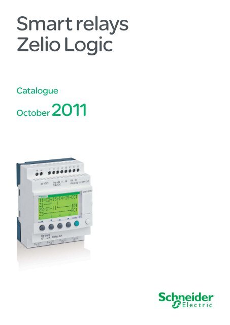
<strong>Smart</strong> <strong>relays</strong><br />
<strong>Zelio</strong> <strong>Logic</strong><br />
Catalogue<br />
October 2011
All technical information about products listed in<br />
this catalogue are now available on:<br />
www.schneider-electric.com<br />
Browse the “product data sheet” to check out :<br />
p characteristics,<br />
p dimensions,<br />
p curves, ...<br />
p and also the links to the user guides and<br />
the CAD files.<br />
1 From the home page, type the model number* into the<br />
“Search” box.<br />
* type the model<br />
number without any<br />
blank, replace “p”<br />
by “ * ”<br />
2 Under ”All” tab, click the model number that interests you.
3 The product data sheet displays.<br />
Example : <strong>Zelio</strong> Time<br />
data sheet<br />
Example : <strong>Zelio</strong> Time<br />
data sheet<br />
Example : <strong>Zelio</strong> Time<br />
data sheet<br />
You can get this information in one single pdf file.<br />
80<br />
89,5<br />
82<br />
U<br />
C<br />
G<br />
R<br />
22,5<br />
t1<br />
78<br />
t2 t'1 t'2<br />
U<br />
C<br />
G<br />
R<br />
t1<br />
t2 t'1 t'2<br />
Discover this product<br />
p Characteritics<br />
p Functions<br />
p Connection<br />
p Dimensions<br />
p Download &<br />
Documents<br />
Other products<br />
p Help me to choose<br />
Accessories<br />
p Plug<br />
p Sockets
1<br />
2<br />
3<br />
4<br />
5<br />
6<br />
7<br />
8<br />
9<br />
10<br />
2
Contents<br />
<strong>Zelio</strong> <strong>Logic</strong><br />
<strong>Smart</strong> <strong>relays</strong><br />
Selection guide . . . . . . . . . . . . . . . . . . . . . . . . . . . . . . . . . . . . . . . . . . pages 4 to 7<br />
b Compact and modular smart <strong>relays</strong><br />
v Presentation ..................................................................................... pages 8 to 11<br />
v Functions ........................................................................................pages 12 to 14<br />
v Description ............................................................................................... page 15<br />
v References .....................................................................................pages 16 to 21<br />
b Communication<br />
v Presentation ............................................................................................. page 22<br />
b Programming protocol<br />
v Description ............................................................................................... page 23<br />
b Modbus slave communication protocol<br />
v Presentation ............................................................................................. page 24<br />
v Description ............................................................................................... page 25<br />
v Functions .................................................................................................. page 26<br />
b Ethernet server communication protocol<br />
v Presentation, description .......................................................................... page 27<br />
v Functions .................................................................................................. page 28<br />
b Communication<br />
v References ............................................................................................... page 29<br />
b Analogue I/O extension modules<br />
v Presentation, description .......................................................................... page 30<br />
v References ..............................................................................................pages 31<br />
b Modem communication interface<br />
v Presentation, description .............................................................pages 32 and 33<br />
v Functions, setting-up ...................................................................pages 34 and 35<br />
v References ..................................................................................pages 36 and 37<br />
b Analogue interfaces<br />
Selection guide . . . . . . . . . . . . . . . . . . . . . . . . . . . . . . . . . . . . . . .pages 38 and 39<br />
v Presentation ................................................................................pages 40 and 41<br />
v References ..................................................................................pages 42 and 43<br />
b Powers supplies and transformers<br />
v Presentation, description .......................................................................... page 44<br />
v References ............................................................................................... page 45<br />
3<br />
1<br />
2<br />
3<br />
4<br />
5<br />
6<br />
7<br />
8<br />
9<br />
10
1<br />
2<br />
3<br />
4<br />
5<br />
6<br />
7<br />
8<br />
9<br />
10<br />
Selection guide <strong>Zelio</strong> <strong>Logic</strong> - <strong>Smart</strong> <strong>relays</strong><br />
Compact smart <strong>relays</strong><br />
Product type Compact smart <strong>relays</strong><br />
Supply voltage a 24 V a 48 V<br />
Number of I/O 12 20 20<br />
Number of discrete inputs<br />
(of which analogue inputs)<br />
8 (0) 12 (0) 12 (0)<br />
Number of “relay”/“transistor” outputs 4/0 8/0 8/0<br />
With display, with clock<br />
Programming language<br />
With display, without clock<br />
Programming language<br />
Without display, with clock<br />
Programming language<br />
Without display, without clock<br />
Programming language<br />
Programming software (see page 10) “<strong>Zelio</strong> Soft 2” SR2 SFT01<br />
Connection<br />
accessories<br />
(see page 20)<br />
4<br />
Serial link cable SR2 CBL01<br />
USB connecting cable SR2 USB01<br />
XBT connecting cable SR2 CBL08<br />
Bluetooth interface SR2 BTC01<br />
SR2 Bpp1B<br />
_<br />
FBD (1) or LADDER<br />
_ SR2 A201E<br />
LADDER only<br />
SR2 Epp1B<br />
_<br />
FBD (1) or LADDER<br />
_ _<br />
Memory cartridge (see page 20) SR2 MEM02<br />
(d incompatible with SR2 COM01)<br />
“Discovery” packs (see page 18) _<br />
Modem communication interface (see page 36) SR2 COM01<br />
Analogue (PSTN) or GSM modem (see page 36) SR2 MOD0p<br />
Alarm management software (see page 37) “<strong>Zelio</strong> <strong>Logic</strong> Alarm” SR2 SFT02<br />
Converters (thermocouple types J and K,<br />
Pt100 probes and voltage/current) (see page 40) (2)<br />
Power supplies for d.c. control circuit<br />
(see page 44)<br />
_<br />
_<br />
References SR2 ppp1B SR2 A201E<br />
Pages 16 and 17 16<br />
(1) FBD: Function Block Diagram.<br />
(2) See <strong>Zelio</strong> Analog analogue interfaces, page 40.
a 100…240 V c 12 V c 24 V<br />
10 12 20 12 20 10 12 20<br />
6 (0) 8 (0) 12 (0) 8 (4) 12 (6) 6 (0) 8 (4) 12 (2), 12 (6)<br />
4/0 4/0 8/0 4/0 8/0 4/0 4/0, 0/4 8/0, 0/8<br />
SR2 Bppp1FU<br />
FBD (1) or LADDER<br />
SR2 Appp1FU<br />
LADDER only<br />
SR2 Eppp1FU<br />
FBD (1) or LADDER<br />
SR2 Dppp1FU<br />
LADDER only<br />
SR2 Bpp1JD<br />
FBD (1) or LADDER<br />
SR2 BpppBD<br />
FBD (1) or LADDER<br />
_ SR2 ApppBD<br />
LADDER only<br />
_ SR2 EpppBD<br />
FBD (1) or LADDER<br />
_ SR2 DpppBD<br />
LADDER only<br />
SR2 PACKpFU _ SR2 PACKpBD<br />
SR2 COM01 (for SR2 B and SR2 E) SR2 COM01 SR2 COM01 (for SR2 B and SR2 E)<br />
SR2 MOD0p SR2 MOD0p SR2 MOD0p<br />
“<strong>Zelio</strong> <strong>Logic</strong> Alarm” SR2 SFT02 “<strong>Zelio</strong> <strong>Logic</strong> Alarm” SR2 SFT02 “<strong>Zelio</strong> <strong>Logic</strong> Alarm” SR2 SFT02<br />
_ RMp pppBD<br />
_ ABL 8MEM12020 ABL 8MEM240pp<br />
ABL 7RM24025<br />
SR2 ppp1FU SR2 Bpp1JD SR2 ppppBD<br />
16 and 17 16 16 and 17<br />
5<br />
1<br />
2<br />
3<br />
4<br />
5<br />
6<br />
7<br />
8<br />
9<br />
10
1<br />
2<br />
3<br />
4<br />
5<br />
6<br />
7<br />
8<br />
9<br />
10<br />
Selection guide <strong>Zelio</strong> <strong>Logic</strong>- <strong>Smart</strong> <strong>relays</strong><br />
Modular smart <strong>relays</strong> and I/O extension and<br />
communication modules<br />
Product type Modular smart <strong>relays</strong><br />
Supply voltage a 24 V a 100...240 V<br />
Number of I/O 10 26<br />
Number of discrete inputs<br />
(of which analogue inputs)<br />
6 (0) 16 (0)<br />
Number of “relay”/“transistor” outputs 4/0 10/0<br />
With display, with clock Yes<br />
FBD or LADDER<br />
Programming language<br />
Programming software (see page 10) “<strong>Zelio</strong> Soft 2” SR2 SFT01<br />
Connection<br />
accessories<br />
(see page 20)<br />
6<br />
Serial link cable SR2 CBL01<br />
USB connecting cable SR2 USB01<br />
XBT connecting cable SR2 CBL08<br />
Bluetooth interface SR2 BTC01<br />
Memory cartridge (see page 20) SR2 MEM02<br />
(d incompatible with SR2 COM01)<br />
“Discovery” packs (see page 18) _ SR3 PACKpBD<br />
Modem communication interface (see page 36) SR2 COM01<br />
Analogue (PSTN) or GSM modem (see page 36) SR2 MOD0p<br />
Alarm management software (see page 37) “<strong>Zelio</strong> <strong>Logic</strong> Alarm” SR2 SFT02<br />
Converters (thermocouple types J and K,<br />
Pt100 probes and voltage/current) (see page 40) (1)<br />
Power supplies for d.c. control circuit<br />
(see page 44)<br />
_<br />
_<br />
References (see page 19) SR3 Bpp1B SR3 Bpp1FU<br />
(1) See <strong>Zelio</strong> Analog analogue interfaces, page 40.<br />
Associated I/O extension and<br />
communication module types<br />
Discrete I/O extension modules<br />
Number of I/O 6 10 14<br />
Type and number of discrete inputs<br />
(or analogue inputs)<br />
4 (0) 6 (0) 8 (0)<br />
Type and number of relay outputs<br />
(or analogue outputs)<br />
2 (0) 4 (0) 6 (0)<br />
References SR3 XTpppB SR3 XTpppFU<br />
Pages 19
c 12 V c 24 V<br />
26 10 26<br />
16 (6) 6 (4) 16 (6)<br />
10/0 4/0, 0/4 10/0, 0/10<br />
_ SR3 PACKpBD<br />
RMp pppBD<br />
ABL 8MEM12020 ABL 8MEM24006, ABL 8MEM24012, ABL 7RM24025<br />
SR3 B261JD SR3 BpppBD<br />
Discrete I/O extension modules Network communication modules I/O extension modules<br />
Modbus salve Ethernet server Analogue Discrete<br />
or and<br />
or<br />
6 10 14 b Number of words: b Number of words: 4 6 10 14<br />
4 (0) 6 (0) 8 (0) v 4 (inputs)<br />
v 4 (outputs)<br />
v 4 (inputs)<br />
v 4 (outputs)<br />
0 (2) 4 (0) 6 (0) 8 (0)<br />
2 (0) 4 (0) 6 (0)<br />
v 4 (clock)<br />
v 1 (status)<br />
v 4 (clock)<br />
v 1 (status)<br />
0 (2) 2 (0) 4 (0) 6 (0)<br />
SR3 XTpppJD SR3 MBU01BD SR3 NET01BD SR3 XT43BD SR3 XTpppBD<br />
19 29 31 19<br />
7<br />
1<br />
2<br />
3<br />
4<br />
5<br />
6<br />
7<br />
8<br />
9<br />
10
1<br />
2<br />
3<br />
4<br />
5<br />
6<br />
7<br />
8<br />
9<br />
10<br />
Presentation <strong>Zelio</strong> <strong>Logic</strong> - <strong>Smart</strong> <strong>relays</strong><br />
Compact and modular smart <strong>relays</strong><br />
<strong>Zelio</strong> <strong>Logic</strong> compact smart relay<br />
Combination of modular smart <strong>relays</strong> with<br />
communication and I/O extension modules<br />
1 2<br />
1 <strong>Zelio</strong> <strong>Logic</strong> modular smart relay<br />
(10 or 26 I/O)<br />
2 I/O extension module: discrete<br />
(6,10 or 14 I/O) or analogue (4 I/O)<br />
1 2 3<br />
1 <strong>Zelio</strong> <strong>Logic</strong> modular smart relay<br />
(10 or 26 I/0)<br />
2 Modbus or Ethernet communication<br />
modules<br />
3 I/O extension module: discrete<br />
(6,10 or 14 I/O) or analogue (4 I/O)<br />
d The order shown above must be observed when using<br />
a Modbus slave or Ethernet server communication<br />
module and a discrete or analogue I/O extension module.<br />
An I/O extension module cannot be fitted before the<br />
Modbus slave communication module.<br />
8<br />
Presentation<br />
<strong>Zelio</strong> <strong>Logic</strong> smart <strong>relays</strong> are designed for use in small automated systems. They are<br />
used in both the industrial and commercial sectors.<br />
b For industry:<br />
v automation of small finishing, production, assembly or packaging machines,<br />
v decentralised automation of ancillary equipment of large and medium-sized<br />
machines (textile, plastics, materials processing sectors, etc.),<br />
v automation systems for agricultural machinery (irrigation, pumping, greenhouses<br />
etc.)<br />
b For the commercial/building sectors:<br />
v automation of barriers, roller shutters, access control,<br />
v automation of lighting systems,<br />
v automation of compressors and air conditioning systems.<br />
v etc.<br />
Their compact size and ease of setting-up make them a competitive alternative to<br />
solutions based on cabled logic or specific cards.<br />
b Programming<br />
Simple programming, ensured by the universal nature of the languages, meets all<br />
the requirements of automation specialists and also the needs of the electrician.<br />
Programming can be performed:<br />
v independently, using the buttons on the <strong>Zelio</strong> <strong>Logic</strong> smart relay (ladder language),<br />
v on a PC using “<strong>Zelio</strong> Soft 2” software.<br />
When using a PC, programming can be performed either in LADDER language or in<br />
function block diagram (FBD) language, see page 10.<br />
Backlighting of the LCD display (1) is obtained by activating one of the 6<br />
programming buttons on the <strong>Zelio</strong> <strong>Logic</strong> smart relay or by programming with “<strong>Zelio</strong><br />
Soft 2” software (example: flashing in the event of a malfunction).<br />
The autonomous operating time of the clock, assured by a lithium battery, is 10<br />
years.<br />
Data backup (preset values and current values) is provided by an EEPROM Flash<br />
memory (10 years).<br />
Compact smart <strong>relays</strong><br />
Compact smart <strong>relays</strong> meet requirements for simple automation systems.<br />
The number of inputs/outputs can be:<br />
b 12 or 20 I/O, supplied with a 24 V or c 12 V,<br />
b 20 I/O, supplied with a 48 V,<br />
b 10, 12 or 20 I/O, supplied with a 100…240 V or c 24 V.<br />
Modular smart <strong>relays</strong> and extensions<br />
The number of inputs/outputs for modular smart <strong>relays</strong> can be:<br />
b 26 I/O, supplied with c 12 V,<br />
b 10 or 26 I/O, supplied with a 24 V, a 100…240 V or c 24 V<br />
To improve performance and flexibility, <strong>Zelio</strong> <strong>Logic</strong> modular smart <strong>relays</strong> can be fitted<br />
with communication modules and I/O extension modules to obtain a maximum of<br />
40 I/O:<br />
b Modbus or Ethernet communication modules, supplied with c 24 V via the<br />
<strong>Zelio</strong> <strong>Logic</strong> smart relay at the same voltage.<br />
b analogue I/O extension modules with 4 I/O, supplied with c 24 V via the<br />
<strong>Zelio</strong> <strong>Logic</strong> smart relay at the same voltage,<br />
b discrete I/O extension modules with 6, 10 or 14 I/O, supplied via the <strong>Zelio</strong> <strong>Logic</strong><br />
smart relay at the same voltage.<br />
(1) LCD: Liquid Crystal Display.
Presentation (continued)<br />
Connecting cable<br />
Memory cartridge<br />
Modbus<br />
communication module<br />
Modem<br />
communication interface<br />
Bluetooth interface<br />
Ethernet<br />
communication module<br />
Analogue PSTN Modem<br />
GSM modem<br />
<strong>Zelio</strong> <strong>Logic</strong> - <strong>Smart</strong> <strong>relays</strong><br />
Compact and modular smart <strong>relays</strong><br />
Communication<br />
Cabled and wireless programming tools<br />
b These programming tools allow the <strong>Zelio</strong> <strong>Logic</strong> smart relay to be connected to a PC<br />
running “<strong>Zelio</strong> Soft 2” software:<br />
v Link by cables:<br />
- Cable SR2 CBL01 to 9-pin serial port<br />
or<br />
- Cable SR2 USB01 to USB port<br />
v Wireless link:<br />
- Bluetooth interface SR2 BTC01<br />
b Memory cartridge<br />
The <strong>Zelio</strong> <strong>Logic</strong> smart relay can be fitted with a backup memory cartridge which<br />
enables the application program to be copied into another <strong>Zelio</strong> <strong>Logic</strong> smart relay.<br />
However, loading and updating of the firmware (software embedded in the product)<br />
is only possible with memory cartridge SR2 MEM02.<br />
The memory cartridge also enables a backup copy of the program to be saved prior<br />
to replacing the product.<br />
When used with a smart relay without display or buttons, the copy of the program<br />
contained in the cartridge is automatically transferred into the <strong>Zelio</strong> <strong>Logic</strong> smart relay<br />
on power-up.<br />
Modbus slave and Ethernet server communication modules<br />
Modbus and Ethernet communication modules allow connection to automation<br />
system equipment such as display units or programmable controllers (see page 22).<br />
Modem communication interface<br />
The “Modem communication interface” products in the <strong>Zelio</strong> <strong>Logic</strong> range include:<br />
b a Modem communication interface SR2 COM01 connected between a <strong>Zelio</strong> <strong>Logic</strong><br />
smart relay and a Modem,<br />
b analogue (PSTN) (1) SR2 MOD01 or GSM (2) SR2 MOD02, Modems<br />
b “<strong>Zelio</strong> <strong>Logic</strong> Alarm” software SR2 SFT02.<br />
They are designed for monitoring or remote control of machines or installations<br />
which operate without personnel.<br />
The Modem communication interface, supplied with c 12...24 V, enables messages,<br />
telephone numbers and calling conditions to be stored, see page 32.<br />
(1) Public Switched Telephone Network.<br />
(2) Global System Mobile.<br />
9<br />
1<br />
2<br />
3<br />
4<br />
5<br />
6<br />
7<br />
8<br />
9<br />
10
1<br />
2<br />
3<br />
4<br />
5<br />
6<br />
7<br />
8<br />
9<br />
10<br />
Presentation<br />
Programming in FBD language<br />
Simulation mode<br />
Monitoring window<br />
10<br />
<strong>Zelio</strong> <strong>Logic</strong> - <strong>Smart</strong> <strong>relays</strong><br />
Compact and modular smart <strong>relays</strong><br />
“<strong>Zelio</strong> Soft 2” programming software<br />
“<strong>Zelio</strong> Soft 2” for PC - version 4.4 (1)<br />
“<strong>Zelio</strong> Soft 2” software enables:<br />
b programming in LADDER language or in function block diagram (FBD) language,<br />
see page 8,<br />
b simulation, monitoring and supervision,<br />
b uploading and downloading of programs,<br />
b output of personalised files,<br />
b automatic compiling of programs,<br />
b on-line help.<br />
Coherence tests and application languages<br />
“<strong>Zelio</strong> Soft 2” software monitors applications by means of its coherence test function.<br />
An indicator turns red at the slightest input error. The problem can be located by<br />
simply clicking the mouse.<br />
“<strong>Zelio</strong> Soft 2” software allows switching, at any time, to any of the 6 languages<br />
(English, French, German, Spanish, Italian, Portuguese) and editing of the<br />
application file in the selected language.<br />
Inputting messages for display on <strong>Zelio</strong> <strong>Logic</strong><br />
“<strong>Zelio</strong> Soft 2” software allows Text function blocks to be configured, which can then<br />
be displayed on all <strong>Zelio</strong> <strong>Logic</strong> smart <strong>relays</strong> which have a display.<br />
Program testing<br />
2 test modes are provided:<br />
b “<strong>Zelio</strong> Soft 2” simulation mode allows a program to be tested without a <strong>Zelio</strong> <strong>Logic</strong><br />
smart relay, i.e.:<br />
v enable discrete inputs,<br />
v display the status of outputs,<br />
v vary the voltage of the analogue inputs,<br />
v enable the programming buttons,<br />
v simulate the application program in real time or in accelerated time,<br />
v dynamically display (in red) the various active elements of the program.<br />
b “<strong>Zelio</strong> Soft 2” monitoring mode makes it possible to test the program executed by<br />
the smart relay, i.e.:<br />
v display the program “on-line”,<br />
v force inputs, outputs, control <strong>relays</strong> and current values of the function blocks,<br />
v adjust the time,<br />
v change from STOP mode to RUN mode and vice versa.<br />
In simulation or monitoring mode, the monitoring window allows the status of the<br />
smart relay I/Os to be displayed within your application environment (diagram or<br />
image).<br />
(1) These functions exist for all versions u V 4.1.
Presentation (continued)<br />
Structure of a split wiring sheet<br />
2 1<br />
“Acceleration and simulation terminals” window<br />
1<br />
2<br />
3<br />
4<br />
5<br />
6<br />
7<br />
<strong>Zelio</strong> <strong>Logic</strong> - <strong>Smart</strong> <strong>relays</strong><br />
Compact and modular smart <strong>relays</strong><br />
“<strong>Zelio</strong> Soft 2” programming software<br />
User interfaces<br />
“<strong>Zelio</strong> Soft 2” software (versions u 4.1) improves, amongst other things, the ease of<br />
use of user interfaces for the following functions:<br />
“Split wiring sheet” function (FBD language)<br />
The wiring sheet can be split into 2. Splitting allows two separate parts of the wiring<br />
sheet to be displayed on the same screen.<br />
This makes it possible to:<br />
b Display the required function blocks in the top and bottom parts.<br />
b Move the split bar as required.<br />
b Connect the function blocks between the 2 parts of the wiring sheet.<br />
The split wiring sheet is structured as follows:<br />
1 View of top part<br />
2 Top window vertical scroll bar<br />
3 Top window horizontal scroll bar<br />
4 Split bar<br />
5 View of bottom part<br />
6 Bottom window vertical scroll bar<br />
7 Bottom window horizontal scroll bar<br />
“Replacement of a function block” (FBD language)<br />
A function allows a block to be replaced without losing the input and output<br />
connections.<br />
E.g.: Replacement of an “OR” block by a “NOR” block.<br />
1 “OR” block to be replaced<br />
zzzz<br />
2 Move all links to the new “NOR” block<br />
“Time Prog Simulation” function (LADDER and FBD languages)<br />
LADDER or FBD program simulation mode allows the program to be debugged by<br />
simulating it on the software workshop host computer.<br />
A function allows the time on the simulator clock to be modified by setting to 3<br />
seconds before the start of the next event.<br />
The “Next event” button 1 allows modification of the simulator clock 2.<br />
2<br />
1<br />
3 Delete the “OR” block and position<br />
the “NOR” block in its place<br />
11<br />
3<br />
1<br />
2<br />
3<br />
4<br />
5<br />
6<br />
7<br />
8<br />
9<br />
10
1<br />
2<br />
3<br />
4<br />
5<br />
6<br />
7<br />
8<br />
9<br />
10<br />
Functions<br />
LADDER language<br />
Definition<br />
Text function block<br />
Up/down counter<br />
Analogue comparator<br />
Control relay<br />
LCD backlighting<br />
Output coil<br />
12<br />
Timer<br />
Fast counter<br />
Clock<br />
Counter comparator<br />
Summer/Winter time switching<br />
Message<br />
LADDER language enables a LADDER program to be written with elementary<br />
functions, elementary function blocks and derived function blocks, as well as with<br />
contacts, coils and variables.<br />
The contacts, coils and variables can be annotated. Text can be placed freely within<br />
the graphic.<br />
b Control scheme input modes<br />
“<strong>Zelio</strong> input” mode enables users who have directly programmed the <strong>Zelio</strong> <strong>Logic</strong><br />
smart relay to find the same user interface, even when using the software for the first<br />
time.<br />
“Free input” mode, which is more intuitive, is very user-friendly and incorporates<br />
many additional features.<br />
With LADDER programming language, two alternative types of symbol can be used:<br />
v LADDER symbols,<br />
v electrical symbols.<br />
“Free input” mode also allows the creation of mnemonics and notes associated with<br />
each line of the program.<br />
Instant switching from one input mode to the other is possible at any time, by simply<br />
clicking the mouse.<br />
Up to 120 control scheme lines can be programmed, with 5 contacts and 1 coil per<br />
program line<br />
b Functions:<br />
v 16 Text function blocks,<br />
v 16 time delay function blocks; parameters of 11 different types can be set for each<br />
of these (1/10 th second to 9999 hours),<br />
v 16 up/down counter function blocks from 0 to 32767,<br />
v 1 fast counter (1 kHz),<br />
v 16 analogue comparator function blocks,<br />
v 8 clock function blocks, each with 4 channels,<br />
v 28 control <strong>relays</strong>,<br />
v 8 counter comparators,<br />
v LCD screen with programmable backlighting,<br />
v automatic Summer/Winter time switching,<br />
v variety of functions: coil, latching (Set/Reset), impulse relay, contactor,<br />
v 28 message blocks (with communication interface, see page 32).<br />
Functions<br />
Function Electrical scheme LADDER language Notes<br />
Contact I corresponds to the real state of the contact connected to the<br />
I<br />
input of the smart relay.<br />
or or<br />
i<br />
i corresponds to the inverse state of the contact connected to<br />
the input of the smart relay.<br />
13<br />
14<br />
22 21<br />
Standard coil The coil is energised when the contacts to which it is connected<br />
are closed.<br />
A1<br />
A2<br />
Latch coil (Set) The coil is energised (set) when the contacts to which it is<br />
S<br />
connected are closed. It remains set even if the contacts are no<br />
longer closed.<br />
A1<br />
A2<br />
Unlatch coil (Reset) The coil is de-energised (reset) when the contacts to which it is<br />
R<br />
connected are closed.<br />
It remains disabled even if the contacts are no longer closed.<br />
A1<br />
A2<br />
<strong>Zelio</strong> <strong>Logic</strong> - <strong>Smart</strong> <strong>relays</strong><br />
Compact and modular smart <strong>relays</strong><br />
“<strong>Zelio</strong> Soft 2” programming software
Functions (continued)<br />
Function block diagram language (FBD / Grafcet SFC / <strong>Logic</strong> functions) (1)<br />
Definition<br />
FBD language allows graphical programming based on the use of predefined function blocks; it provides the use of:<br />
b 34 pre-programmed functions for counting, time delay, timing, definition of switching threshold, (for example: temperature regulation),<br />
generation of impulses, time programming, multiplexing, display,<br />
b 7 SFC functions,<br />
b 6 logic functions.<br />
Pre-programmed functions<br />
<strong>Zelio</strong> <strong>Logic</strong> smart <strong>relays</strong> provide a high processing capacity, up to 200 function blocks, including 34 pre-programmed functions:<br />
TIMER AC TIMER BH TIMER Li TIMER BW<br />
Timer. Function A/C<br />
(ON-delay and OFF-delay)<br />
Timer. Function BH.<br />
(adjustable pulsed signal)<br />
Pulse generator<br />
(ON-delay, OFF-delay)<br />
Timer. Function BW<br />
(pulse on rising/falling edge)<br />
TIMER AC TIMER BH TIMER Li BISTABLE SET- RESET<br />
Timer. Function A/C with<br />
external preset adjustment<br />
(ON-delay and OFF-delay)<br />
Timer. Function BH with<br />
external preset adjustment<br />
(adjustable pulsed signal)<br />
Pulse generator with<br />
external preset adjustment<br />
(ON-delay, OFF-delay)<br />
Impulse relay function Bistable latching<br />
- Priority assigned either to<br />
SET or RESET function<br />
BOOLEAN CAM PRESET COUNT UP DOWN COUNT PRESET H-METER<br />
Allows logic equations to be<br />
created between connected<br />
inputs<br />
Cam programmer Up/down counter Up/down counter<br />
with external preset<br />
Hour counter<br />
(hour, minute preset)<br />
TIME PROG GAIN TRIGGER MUX COMP IN ZONE<br />
Time programmer,<br />
weekly and annual.<br />
Allows conversion of an<br />
analogue value by<br />
change of scale and offset.<br />
Defines an activation zone with<br />
hysteresis<br />
Multiplexing functions<br />
on 2 analogue values<br />
Zone comparison<br />
(Min. y Value y Max.)<br />
ADD/SUB MUL/DIV TEXT DISPLAY COM<br />
Add and/or subtract function Multiply and/or divide function Display of 4 pieces of data:<br />
digital, analogue, date,<br />
time, messages for<br />
Human-Machine interface.<br />
Display of digital and analogue<br />
data, date, time, messages for<br />
Human-Machine interface.<br />
COMPARE STATUS ARCHIVE SPEED COUNT CAN<br />
Comparison of 2 analogue<br />
values using the operands<br />
=, >,
1<br />
2<br />
3<br />
4<br />
5<br />
6<br />
7<br />
8<br />
9<br />
10<br />
Functions (continued)<br />
Function block diagram language (FBD / Grafcet SFC / <strong>Logic</strong> functions) (continued)<br />
Macro Function<br />
14<br />
Creation of a Macro<br />
1 5 2 3 4 6<br />
Inside of a Macro<br />
1 Macro selection<br />
2 Edit properties<br />
3 Allows return to external view of a Macro<br />
4 Internal function block within the Macro<br />
5 Non connected inputs<br />
6 Non connected outputs<br />
<strong>Zelio</strong> <strong>Logic</strong> - <strong>Smart</strong> <strong>relays</strong><br />
Compact and modular smart <strong>relays</strong><br />
“<strong>Zelio</strong> Soft 2” programming software<br />
A Macro is a grouping of function blocks. It is characterised by its number, its name,<br />
its links, its internal function blocks (255 max.) and by its I/O connections.<br />
Seen from the outside, a Macro behaves like a function block with inputs and/or<br />
outputs that can be connected to links.<br />
Once created, a Macro can be manipulated like a function block.<br />
b Macro characteristics:<br />
v The maximum number of Macros is 64.<br />
v A password dedicated to Macros can be used to protect their content,<br />
v A Macro can be edited / duplicated,<br />
v A Macro's comments can be edited.<br />
b Macro properties:<br />
A “Macro properties” dialogue box allows the properties of a Macro to be entered or<br />
edited.<br />
The properties of a Macro are:<br />
v Macro name (optional)<br />
v The block Symbol, which may be:<br />
- an identifier,<br />
- an image.<br />
v Name of inputs.<br />
v Name of outputs.
Description<br />
Compact smart <strong>relays</strong><br />
With display - 10, 12 and 20 I/O Without display - 10, 12 and 20 I/O<br />
Modular smart <strong>relays</strong><br />
With display - 10 and 26 I/O<br />
Discrete I/O extension modules<br />
6 discrete I/O 10 and 14 discrete I/O<br />
1 2<br />
1 2<br />
4<br />
5<br />
5<br />
1<br />
1<br />
2<br />
2<br />
6<br />
6<br />
3<br />
1<br />
7<br />
7<br />
3<br />
3<br />
4<br />
5<br />
5<br />
1<br />
1<br />
3<br />
4<br />
5<br />
4<br />
5<br />
<strong>Zelio</strong> <strong>Logic</strong> - <strong>Smart</strong> <strong>relays</strong><br />
Compact and modular smart <strong>relays</strong><br />
1<br />
1 2 3<br />
7<br />
1<br />
5<br />
<strong>Zelio</strong> <strong>Logic</strong> compact smart <strong>relays</strong> have the<br />
following on their front panel:<br />
1 Two retractable mounting feet<br />
2 Two power supply terminals.<br />
3 Terminals for connection of the inputs.<br />
4 Backlit LCD display with 4 lines of 18<br />
characters.<br />
5 Slot for memory cartridge or connection<br />
to a PC or Modem communication<br />
interface.<br />
6 6 buttons for programming and<br />
parameter entry.<br />
7 Terminals for connection of the outputs<br />
<strong>Zelio</strong> <strong>Logic</strong> modular smart <strong>relays</strong> have the<br />
following on their front panel:<br />
1 Two retractable mounting feet<br />
2 Two power supply terminals.<br />
3 Terminals for connection of the inputs.<br />
4 Backlit LCD display with 4 lines of 18<br />
characters.<br />
5 Slot for memory cartridge or connection<br />
to a PC or Modem communication<br />
interface.<br />
6 6 buttons for programming and<br />
parameter entry.<br />
7 Terminals for connection of the outputs<br />
Discrete I/O extension modules have the<br />
following on their front panel:<br />
1 Two retractable mounting feet<br />
2 Terminals for connection of the inputs.<br />
3 Terminals for connection of the outputs<br />
4 A connector for connection to the <strong>Zelio</strong><br />
<strong>Logic</strong> smart relay (powered via the <strong>Zelio</strong><br />
<strong>Logic</strong> smart relay).<br />
5 Locating pegs.<br />
15<br />
1<br />
2<br />
3<br />
4<br />
5<br />
6<br />
7<br />
8<br />
9<br />
10
1<br />
2<br />
3<br />
4<br />
5<br />
6<br />
7<br />
8<br />
9<br />
10<br />
References<br />
SR2 A201BD<br />
SR2 SFT01<br />
SR2 PACKppp<br />
Modem communication interface<br />
16<br />
<strong>Zelio</strong> <strong>Logic</strong> - <strong>Smart</strong> <strong>relays</strong><br />
Compact smart <strong>relays</strong><br />
Compact smart <strong>relays</strong> with display<br />
Number<br />
of I/O<br />
Discrete<br />
inputs<br />
Including<br />
c 0-10 V<br />
analogue<br />
inputs<br />
Relay Transistor<br />
outputs outputs<br />
Clock Reference Weight<br />
kg<br />
Supply a 24 V<br />
12 8 0 4 0 Yes SR2 B121B 0.250<br />
20 12 0 8 0 Yes SR2 B201B 0.380<br />
Supply a 48 V<br />
20 12 0 8 0 Non SR2 A201E (1) (2) 0,380<br />
Supply a 100...240 V<br />
10 6 0 4 0 No SR2 A101FU (2) 0.250<br />
12 8 0 4 0 Yes SR2 B121FU 0.250<br />
20 12 0 8 0 No SR2 A201FU (2) 0.380<br />
Yes SR2 B201FU 0.380<br />
Supply c 12 V<br />
12 8 4 4 0 Yes SR2 B121JD 0.250<br />
20 12 6 8 0 Yes SR2 B201JD 0.380<br />
Supply c 24 V<br />
10 6 0 4 0 No SR2 A101BD (2) 0.250<br />
12 8 4 4 0 Yes SR2 B121BD 0.250<br />
0 4 Yes SR2 B122BD 0.220<br />
20 12 2 8 0 No SR2 A201BD (2) 0.380<br />
6 8 0 Yes SR2 B201BD 0.380<br />
0 8 Yes SR2 B202BD 0.280<br />
“<strong>Zelio</strong> Soft 2” software<br />
See page 20.<br />
Accessories<br />
See page 20.<br />
Compact “discovery” packs<br />
Number Pack contents:<br />
of I/O - Compact smart relay with display<br />
- “<strong>Zelio</strong> Soft 2” programming software<br />
supplied on CD-Rom<br />
- Cable SR2 USB01 for connection to PC (3)<br />
Description of compact smart relay with display<br />
Supply a 100...240 V<br />
Reference Weight<br />
kg<br />
12 SR2 B121FU SR2 PACKFU 0.700<br />
20 SR2 B201FU SR2 PACK2FU 0.850<br />
Supply c 24 V<br />
12 SR2 B121BD SR2 PACKBD 0.700<br />
20 SR2 B201BD SR2 PACK2BD 0.700<br />
Modem communication interface<br />
Supply c 12...24 V<br />
Description Application Reference Weight<br />
kg<br />
Modem communication<br />
interface<br />
For SR2 B See page 32 0.200<br />
(1) Can only be used with “<strong>Zelio</strong> Soft 2” software version u V 3.1.<br />
(2) Programming on <strong>Zelio</strong> <strong>Logic</strong> smart relay in LADDER language only.<br />
(3) Replaces cable SR2 CBL01 which is available separately, as an accessory (see page 20).
References (continued)<br />
SR2 E121BD<br />
SR2 SFT01<br />
SR2 USB01<br />
Modem communication interface<br />
<strong>Zelio</strong> <strong>Logic</strong> - <strong>Smart</strong> <strong>relays</strong><br />
Compact smart <strong>relays</strong><br />
Compact smart <strong>relays</strong> without display<br />
Number Discrete Including Relay Transistor Clock Reference Weight<br />
of I/O inputs c 0-10 V<br />
analogue<br />
inputs<br />
outputs outputs<br />
kg<br />
Supply a 24 V<br />
12 8 0 4 0 Yes SR2 E121B 0.220<br />
20 12 0 8 0 Yes SR2 E201B 0.350<br />
Supply a 100...240 V<br />
10 6 0 4 0 No SR2 D101FU (1) 0.220<br />
12 8 0 4 0 Yes SR2 E121FU 0.220<br />
20 12 0 8 0 No SR2 D201FU (1) 0.350<br />
Yes SR2 E201FU 0.350<br />
Supply c 24 V<br />
10 6 0 4 0 No SR2 D101BD (1) 0.220<br />
12 8 4 4 0 Yes SR2 E121BD 0.220<br />
20 12 2 8 0 No SR2 D201BD (1) 0.350<br />
“<strong>Zelio</strong> Soft 2” software<br />
See page 20.<br />
6 8 0 Yes SR2 E201BD 0.350<br />
Accessories<br />
See page 20.<br />
Modem communication interface<br />
Supply c 12...24 V<br />
Description Application Reference Weight<br />
kg<br />
Modem communication<br />
interface<br />
For SR2 E See page 32 0.200<br />
(1) Programming on <strong>Zelio</strong> <strong>Logic</strong> smart relay in LADDER language only.<br />
17<br />
1<br />
2<br />
3<br />
4<br />
5<br />
6<br />
7<br />
8<br />
9<br />
10
1<br />
2<br />
3<br />
4<br />
5<br />
6<br />
7<br />
8<br />
9<br />
10<br />
References (continued)<br />
SR3 B261BD<br />
SR2 SFT01<br />
SR2 PACKppp<br />
18<br />
<strong>Zelio</strong> <strong>Logic</strong> - <strong>Smart</strong> <strong>relays</strong><br />
Modular smart <strong>relays</strong><br />
Modular smart <strong>relays</strong> with display<br />
Number Discrete Including<br />
of I/O inputs c 0-10 V<br />
analogue<br />
inputs<br />
Supply a 24 V<br />
Relay Transistor<br />
outputs outputs<br />
Clock Reference Weight<br />
kg<br />
10 6 0 4 0 Yes SR3 B101B 0.250<br />
26 16 0 10 (1) 0 Yes SR3 B261B 0.400<br />
Supply a 100...240 V<br />
10 6 0 4 0 Yes SR3 B101FU 0.250<br />
26 16 0 10 (1) 0 Yes SR3 B261FU 0.400<br />
Supply c 12 V<br />
26 16 6 10 (1) 0 Yes SR3 B261JD (2) 0.400<br />
Supply c 24 V<br />
10 6 4 4 0 Yes SR3 B101BD 0.250<br />
0 4 Yes SR3 B102BD 0.220<br />
26 16 6 10 (1) 0 Yes SR3 B261BD 0.400<br />
“<strong>Zelio</strong> Soft 2” software<br />
See page 20.<br />
Accessories<br />
See page 20.<br />
Modular “discovery” packs<br />
Number Pack contents:<br />
of I/O - Compact smart relay with display<br />
- “<strong>Zelio</strong> Soft 2” programming software<br />
supplied on CD-Rom<br />
- Cable SR2 USB01 for connection to PC (3)<br />
Description of compact smart relay with display<br />
Supply a 100...240 V<br />
0 10 Yes SR3 B262BD 0.300<br />
Reference Weight<br />
kg<br />
10 SR3 B101FU SR3 PACKFU 0.700<br />
26 SR3 B261FU SR3 PACK2FU 0.850<br />
Supply c 24 V<br />
10 SR3 B101BD SR3 PACKBD 0.700<br />
26 SR3 B261BD SR3 PACK2BD 0.850<br />
(1) Includ ing 8 outputs at maximum current of 8 A and 2 outputs at maximum current of 5 A.<br />
(2) Can only be used with “<strong>Zelio</strong> Soft 2” software version u V 3.1.<br />
(3) Replaces cable SR2 CBL01 which is available separately, as an accessory (see page 20).<br />
Note: The <strong>Zelio</strong> <strong>Logic</strong> smart relay and its associated extensions must have an identical voltage.
References (continued) <strong>Zelio</strong> <strong>Logic</strong> - <strong>Smart</strong> <strong>relays</strong><br />
Modular smart <strong>relays</strong><br />
Modbus<br />
communication module<br />
SR3 XT141JD<br />
Modem communication interface<br />
Ethernet<br />
communication module<br />
Modbus and Ethernet communication module (1)<br />
Supply c 24 V (via smart <strong>relays</strong> SR3B...BD)<br />
For use with Network Reference Weight<br />
kg<br />
<strong>Zelio</strong> <strong>Logic</strong> modular smart <strong>relays</strong><br />
SR3 Bpp1BD and SR3 Bpp2BD<br />
Modbus See page 22 0.110<br />
Ethernet See page 22 0.110<br />
Analogue I/O extension module (2)<br />
Supply c 24 V (via <strong>Zelio</strong> logic smart relay SR3 B...BD)<br />
Number Inputs Including c Inclu- Output Reference Weight<br />
of I/O<br />
0-10 V 0-20 mA ding<br />
Pt100<br />
c<br />
0-10 V<br />
kg<br />
4 2 (3) 2 max 2 max 1 max 2 See page 30 0.110<br />
Discrete I/O extension modules<br />
Number<br />
of I/O<br />
Discrete inputs Relay outputs Reference Weight<br />
kg<br />
Supply a 24 V (via <strong>Zelio</strong> <strong>Logic</strong> - <strong>Smart</strong> <strong>relays</strong> SR3 BpppB)<br />
6 4 2 SR3 XT61B 0.125<br />
10 6 4 SR3 XT101B 0.200<br />
14 8 6 (4) SR3 XT141B 0.220<br />
Supply a 100-240 V (via <strong>Zelio</strong> logic smart <strong>relays</strong> SR3 BpppFU)<br />
6 4 2 SR3 XT61FU 0.125<br />
10 6 4 SR3 XT101FU 0.200<br />
14 8 6 (4) SR3 XT141FU 0.220<br />
Supply c 12 V (via <strong>Zelio</strong> logic smart relay SR3 B261JD)<br />
6 4 2 SR3 XT61JD 0.125<br />
10 6 4 SR3 XT101JD 0.200<br />
14 8 6 (4) SR3 XT141JD 0.220<br />
Supply c 24 V (via <strong>Zelio</strong> logic smart <strong>relays</strong> SR3 BpppBD)<br />
6 4 2 SR3 XT61BD 0.125<br />
10 6 4 SR3 XT101BD 0.200<br />
14 8 6 (4) SR3 XT141BD 0.220<br />
Modem communication interface (5)<br />
Supply c 12...24 V<br />
Description Reference Weight<br />
kg<br />
Modem communication interface See page 36 0.200<br />
(1) See page 22.<br />
(2) See page 30.<br />
(3) See page 30.<br />
(4) Including 4 outputs at maximum current of 8 A and 2 outputs at maximum current of 5 A.<br />
(5) See page 32.<br />
Note: The <strong>Zelio</strong> <strong>Logic</strong> smart relay and its associated extensions must have an identical voltage.<br />
19<br />
1<br />
2<br />
3<br />
4<br />
5<br />
6<br />
7<br />
8<br />
9<br />
10
1<br />
2<br />
3<br />
4<br />
5<br />
6<br />
7<br />
8<br />
9<br />
10<br />
References (continued) <strong>Zelio</strong> <strong>Logic</strong> - <strong>Smart</strong> <strong>relays</strong><br />
Compact and modular smart <strong>relays</strong><br />
SR2 SFT01<br />
SR2 USB01<br />
SR2 BTC01<br />
SR2 MEM02<br />
Regulated switch mode<br />
power supply<br />
20<br />
Converters for<br />
thermocouples<br />
Programming<br />
Description Application Reference Weight<br />
kg<br />
“<strong>Zelio</strong> Soft 2” software for PC<br />
Programming software<br />
“<strong>Zelio</strong> Soft 2”,<br />
multi-language<br />
supplied on CD-Rom (1)<br />
Connection accessories<br />
Connecting cables<br />
Length: 3 m<br />
To be used with<br />
“<strong>Zelio</strong> Soft 2” software<br />
Connecting cables<br />
Length: 2.5 m<br />
To be used with<br />
“<strong>Zelio</strong> Soft” software<br />
Bluetooth interface<br />
for <strong>Zelio</strong> <strong>Logic</strong><br />
smart <strong>relays</strong><br />
Bluetooth adapter<br />
for non-equipped PC<br />
Range of 10 m (class 2)<br />
Memory cartridges (4)<br />
EEPROM memory<br />
cartridges<br />
With PC and 32 bits Operating<br />
Systems compatible with<br />
Windows XP, Vista and Windows 7 (2)<br />
SR2 SFT01 0.200<br />
Between the PC (SUB-D, 9-pin<br />
connector) and the <strong>Zelio</strong> <strong>Logic</strong> smart<br />
relay.<br />
SR2 CBL01 0.150<br />
Between the PC (USB connector)<br />
and the <strong>Zelio</strong> <strong>Logic</strong> smart relay.<br />
PC and 32 bits Operating Systems<br />
compatible with Windows XP, Vista and<br />
Windows 7 (2).<br />
SR2 USB01 0.100<br />
Between the Magelis small panel<br />
(XBT N, XBT R or XBT RT) and the<br />
<strong>Zelio</strong> <strong>Logic</strong> smart relay.<br />
PC and 32 bits Operating Systems<br />
compatible with Windows XP, Vista and<br />
Windows 7 (2).<br />
SR2 CBL08 0.100<br />
Between the PC (wireless link)<br />
and the <strong>Zelio</strong> <strong>Logic</strong> smart relay.<br />
Range of 10 m (class 2)<br />
SR2 BTC01 (3) 0.015<br />
To be used in conjunction with<br />
SR 2BTC01 when the PC is not<br />
equipped with Bluetooth technology.<br />
Connection to the USB port on the PC.<br />
PC and 32 bits Operating Systems<br />
compatible with Windows XP, Vista and<br />
Windows 7 (2)<br />
VW3 A8115 0.290<br />
For firmware (software embedded in<br />
the smart relay) version y 2.4<br />
For firmware (software embedded in<br />
the smart relay) version u 3.0<br />
Documentation available on line<br />
User’s manual for direct programming on the <strong>Zelio</strong> <strong>Logic</strong> smart relay<br />
(in french, english, german, spanish, italian or portuguese) :<br />
please consult our internet site www.schneider-electric.com<br />
Regulated switch mode power supplies<br />
Input<br />
voltage<br />
Nominal<br />
output voltage<br />
SR2 MEM01 0.010<br />
SR2 MEM02 0.010<br />
Reference Weight<br />
kg<br />
a 100...240 V (50/60 Hz) c 5 V, c 12 V or c 24 V See page 44 –<br />
Converters<br />
Description Reference Weight<br />
kg<br />
Converters for J and K type thermocouples,<br />
for Pt100 probes and voltage/current<br />
See page 40 –<br />
(1) Supplied on CD-ROM comprising “<strong>Zelio</strong> Soft 2” software, an application library, a self-training<br />
manual, installation instructions and a user’s manual.<br />
(2) Scheduled availability: 4th quarter of 2010 for Windows Vista and Windows 7.<br />
(3) Can only be used with “<strong>Zelio</strong> Soft 2” software version u V 4.1.<br />
(4) Program loading using memory cartridge SR2 MEM02 is incompatible with Modem<br />
communication interface SR2 COM01.
References (continued) <strong>Zelio</strong> <strong>Logic</strong> - <strong>Smart</strong> <strong>relays</strong><br />
Compact and modular smart <strong>relays</strong><br />
14211<br />
14210<br />
Mounting accessories<br />
Description/application Mounting capacity Reference Weight<br />
kg<br />
Dust and damp-proof<br />
enclosure<br />
with split blanking plate<br />
arrangement, fitted with an<br />
IP 55 dust and damp-proof<br />
window with hinged flap, for<br />
mounting through a door<br />
Fixing bracket and<br />
symmetrical mounting rail<br />
- 1 or 2 SR2 smart <strong>relays</strong> with<br />
10 or 12I/O or<br />
- 1 SR2 smart relay with 20 I/O or<br />
- 1 SR3 smart relay with 10 I/O<br />
+ 1 I/O extension module (6, 10 or<br />
14 I/O) or<br />
- 1 SR3 smart relay with 26 I/O<br />
+ 1 I/O extension module (6 I/O).<br />
14210 0.350<br />
For mounting enclosure 14210<br />
through a door panel<br />
14211 0.210<br />
21<br />
1<br />
2<br />
3<br />
4<br />
5<br />
6<br />
7<br />
8<br />
9<br />
10
1<br />
2<br />
3<br />
4<br />
5<br />
6<br />
7<br />
8<br />
9<br />
10<br />
Presentation<br />
<strong>Smart</strong> relay<br />
1 2 3<br />
1 Modular smart relay (10 or 26 I/O).<br />
2 RS 232 serial port, <strong>Zelio</strong> <strong>Logic</strong> type<br />
connector.<br />
3 Modbus slave or Ethernet server<br />
communication module.<br />
4 RJ45 connector for Modbus or Ethernet<br />
network connection.<br />
5 I/O extension module: discrete<br />
(6,10 or 14 I/O) or analogue (4 I/O).<br />
6 Modem communication interface.<br />
7 GSM (or analogue PSTN) Modem.<br />
d The order shown above must be observed when using<br />
a Modbus slave or Ethernet server communication<br />
module and a discrete or analogue I/O extension module.<br />
An I/O extension module cannot be fitted before the<br />
Modbus slave or Ethernet server communication module<br />
22<br />
6<br />
4<br />
5<br />
7<br />
<strong>Zelio</strong> <strong>Logic</strong> - <strong>Smart</strong> <strong>relays</strong><br />
Communication<br />
Presentation<br />
In order to communicate with an intelligent environment, <strong>Zelio</strong> <strong>Logic</strong> - <strong>Smart</strong> <strong>relays</strong><br />
and their I/O extension and communication modules are equipped with various types<br />
of communication port.<br />
bb Compact and modular smart <strong>relays</strong> offer:<br />
vb 1 RS 232 serial port for connection of the PC, the Modem communication interface<br />
or a memory cartridge slot.<br />
bb <strong>Zelio</strong> <strong>Logic</strong> modular smart relay I/O extension and communication modules offer:<br />
vb 1 Modbus RS 485 port on communication module SR3 MBU01BD,<br />
vb 1 Ethernet 10/100 base T port supporting the Modbus TCP protocol on<br />
communication module SR3 NET01BD.<br />
These three ports allow <strong>Zelio</strong> <strong>Logic</strong> compact or modular smart <strong>relays</strong> to use 3<br />
communication protocols:<br />
bb Programming,<br />
bb Modbus,<br />
bb Ethernet.<br />
Communication ports on <strong>Zelio</strong> <strong>Logic</strong> - <strong>Smart</strong> <strong>relays</strong> and their I/O extension<br />
and communication modules:<br />
Communication<br />
port<br />
Serial port Modbus port on<br />
communication<br />
module<br />
SR3 MBU01BD<br />
Ethernet port on<br />
communication<br />
module<br />
SR3 NET01BD<br />
Physical layer RS 232 RS 485 10/100 base T RS 232<br />
Modem<br />
communication<br />
interface port<br />
Connector Specific to <strong>Zelio</strong> RJ45 RJ45 Specific to <strong>Zelio</strong><br />
Compact<br />
smart <strong>relays</strong><br />
Modular<br />
smart <strong>relays</strong><br />
All types<br />
(connection and<br />
isolation via cable<br />
SR2 CBL01 or<br />
SR2 USB01)<br />
All types<br />
(connection and<br />
isolation via cable<br />
SR2 CBL01 or<br />
SR2 USB01)<br />
– – All modules with<br />
clock<br />
SR2 Bppppp<br />
SR2 Eppppp<br />
(see page 36)<br />
All modules with<br />
c 24 V supply<br />
SR3 BpppBD<br />
All modules with<br />
c 24 V supply<br />
SR3 BpppBD<br />
All types<br />
(see page 36)
Description <strong>Zelio</strong> <strong>Logic</strong> - <strong>Smart</strong> <strong>relays</strong><br />
Communication<br />
Programming protocol<br />
Description<br />
1<br />
2<br />
3<br />
4<br />
7<br />
8<br />
11<br />
5<br />
9<br />
10<br />
6<br />
9 12<br />
Link by cable<br />
1 Programming PC.<br />
2 RS 232 serial link cable (SR2 CBL01) or USB cable (SR2 USB01) (1).<br />
3 <strong>Zelio</strong> <strong>Logic</strong> compact or modular smart relay.<br />
Wireless link<br />
4 Programming PC with integrated Bluetooth technology (or Bluetooth adapter<br />
VW3 A8115 for PC not equipped with Bluetooth technology) (1).<br />
5 Bluetooth interface (SR2 BTC01) for <strong>Zelio</strong> <strong>Logic</strong> smart relay (1).<br />
6 <strong>Zelio</strong> <strong>Logic</strong> compact or modular smart relay.<br />
Link by Modem<br />
7 Programming PC.<br />
8 Modem interface connecting cable supplied with SR2 COM01(1).<br />
9 Modem for transmitting/receiving data SR2 MOD01 or SR2 MOD02 (1).<br />
10 Telephone or radio link.<br />
11 Communication interface SR2 COM01.<br />
12 <strong>Zelio</strong> <strong>Logic</strong> compact or modular smart relay.<br />
(1) See page 20.<br />
23<br />
1<br />
2<br />
3<br />
4<br />
5<br />
6<br />
7<br />
8<br />
9<br />
10
1<br />
2<br />
3<br />
4<br />
5<br />
6<br />
7<br />
8<br />
9<br />
10<br />
Presentation,<br />
description,<br />
Modbus communication module<br />
1<br />
7<br />
7<br />
8<br />
8<br />
24<br />
SR3 MBU01BD<br />
COM<br />
PWR<br />
MB485-V1<br />
6 1<br />
3<br />
2<br />
4<br />
5<br />
<strong>Zelio</strong> <strong>Logic</strong> - <strong>Smart</strong> <strong>relays</strong><br />
Communication<br />
Modbus slave communication protocol<br />
Presentation<br />
The Modbus communication protocol is of the master/slave type.<br />
Two exchange methods are possible:<br />
bb Request/reply:<br />
vb The request from the master is addressed to a specific slave.<br />
vb The master waits for the reply to be returned by the slave polled.<br />
bb Distribution:<br />
vb The master distributes a request to all the slave stations on the bus.<br />
These stations execute the instruction without sending a reply.<br />
<strong>Zelio</strong> <strong>Logic</strong> modular smart <strong>relays</strong> are connected to the Modbus network via the<br />
Modbus slave communication module. This module is a slave that is not electrically<br />
isolated.<br />
The Modbus slave communication module must be connected to an SR3 BpppBD<br />
modular smart relay, with a c 24 V supply.<br />
Configuration<br />
The Modbus network slave communication module can be configured:<br />
bb independently, using the buttons on the smart relay (1).<br />
bb on a PC, using “<strong>Zelio</strong> Soft 2” software, see page 10.<br />
When using a PC, programming can be performed either in LADDER language or in<br />
function block diagram (FBD) language, see page 12.<br />
Description<br />
Modbus slave communication module SR3 MBU01BD comprises:<br />
1 Two retractable mounting feet.<br />
2 A Modbus network connection (RJ45 shielded female connector).<br />
3 A communication LED (COM).<br />
4 A “Power on” LED (PWR).<br />
5 A screw terminal block for the protective earth connection.<br />
6 A spring for clip-on mounting on a 35 mm mounting rail.<br />
7 Two locating pegs.<br />
8 Two locating pegs for clip-on fixing.<br />
(1) Programming from the front panel and buttons on the smart relay is only possible in<br />
LADDER language.
Description <strong>Zelio</strong> <strong>Logic</strong> - <strong>Smart</strong> <strong>relays</strong><br />
Communication<br />
Modbus slave communication protocol<br />
1 Twido master.<br />
2 Modbus network (cable TWD XCA RJP03)<br />
3 Slave display unit XUBT N401.<br />
4 Connecting cable XBT Z938.<br />
5 Junction box TWD XCA T3RJ<br />
(polarisation and line end adapter activated).<br />
5 bis Junction box TWD XCA T3RJ (no polarisation<br />
but line end adapter activated).<br />
6 Modbus network (cables VW3 A8 306Rpp).<br />
7 T-junction VW3 A8 306TFpp.<br />
8 ATV 31 variable speed controller.<br />
9 Modbus communication module<br />
SR3 MBU01BD.<br />
10 Modular smart relay SR3 BpppBD.<br />
1 Twido master.<br />
2 Modbus network (cable TWD XCA RJP03)<br />
3 Slave display unit XUBT N401.<br />
4 Connecting cable XBT Z938.<br />
5 Junction box TWD XCA ISO (polarisation and<br />
line end adapter activated).<br />
5 bis Junction box TWD XCA ISO (no polarisation but<br />
line end adapter activated).<br />
6 Modbus network (cables TSX CSA p00).<br />
7 Modbus network (cables VW3 A8 306Rpp).<br />
8 Supply cable c 24 V.<br />
9 Regulated power supply from the Phaseo<br />
Modular range.<br />
10 T-junction 170XTS04100.<br />
11 Modbus communication module<br />
SR3 MBU01BD.<br />
12 Modular smart relay SR3 BpppBD.<br />
Connection examples<br />
Example 1<br />
Total length of cables between Twido and ATV 31: y 30 m<br />
Example 2<br />
y 1000 m<br />
Function description<br />
bb The Modbus slave communication module is connected to a 2-wire or 4-wire<br />
Modbus network (1).<br />
bb The maximum length of the network between the two TWD XCAISO T-junctions is<br />
1000 m (9600 bauds max., AWG 26).<br />
bb A maximum of 32 slaves can be connected to the Modbus network, or a maximum<br />
of 247 slaves with repeaters.<br />
bb Line end adapters must be fitted to both ends of the line (1 nF/10 V, 120 W /0.25 W<br />
in series).<br />
bb The line must be polarised (470 W /0.25 W resistors) (2).<br />
bb The connection cable and its RJ45 male connectors must be shielded.<br />
bb The t terminal on the module must be connected directly to the protective earth<br />
at one point on the bus.<br />
(1) Please refer to installation instructions supplied with the product.<br />
(2) The polarisation resistors must be managed by the master.<br />
25<br />
1<br />
2<br />
3<br />
4<br />
5<br />
6<br />
7<br />
8<br />
9<br />
10
1<br />
2<br />
3<br />
4<br />
5<br />
6<br />
7<br />
8<br />
9<br />
10<br />
Functions<br />
Software workshop<br />
parameter entry window<br />
Input words Output words<br />
J1<br />
XT1<br />
J2<br />
XT1<br />
J3<br />
XT1<br />
J4<br />
XT1<br />
26<br />
3<br />
7 2<br />
3<br />
7 2<br />
3<br />
7 2<br />
3<br />
7 2<br />
FDB program Editing window<br />
4<br />
4<br />
4<br />
4<br />
3<br />
3<br />
3<br />
3<br />
0 9<br />
0 9<br />
0 9<br />
0 9<br />
01<br />
XT1<br />
02<br />
XT1<br />
03<br />
XT1<br />
04<br />
XT1<br />
<strong>Zelio</strong> <strong>Logic</strong> - <strong>Smart</strong> <strong>relays</strong><br />
Communication<br />
Modbus slave communication protocol<br />
Parameter entry<br />
Parameters can be entered either using “<strong>Zelio</strong> Soft 2” software, or directly using the<br />
buttons on the <strong>Zelio</strong> <strong>Logic</strong> smart relay (1).<br />
When the “RUN” instruction is given, the <strong>Zelio</strong> <strong>Logic</strong> smart relay initialises the<br />
Modbus network slave communication module in a configuration previously defined<br />
in the basic program.<br />
The Modbus slave communication module has 4 parameters:<br />
bb number of UART wires and format of the frames on the Modbus network,<br />
bb transmission speed,<br />
bb parity,<br />
bb network address of the Modbus module.<br />
The default parameter settings are as follows: 2-wire, RTU, 19 200 bauds, even<br />
parity, address n° 1.<br />
Parameter entry Options<br />
Number of wires 2 or 4<br />
Frame format RTU or ASCII<br />
Transmission speed<br />
in bauds<br />
1200, 2400, 4800, 9600, 19 200, 28 800, 38 400, 57 600<br />
Parity None, even, odd<br />
Network address 1 to 247<br />
Addressing of Modbus exchanges<br />
LADDER programming<br />
In LADDER mode, the 4 data words (16 bits) to be exchanged cannot be accessed<br />
by the application. Transfers with the master are implicit and are effected in a way<br />
that is totally transparent.<br />
Modbus exchanges Code Number of words<br />
Image of smart relay I/O Read<br />
03<br />
4<br />
Clock words<br />
Status words Read<br />
03<br />
Read/Write<br />
16, 06 or 03<br />
Function block diagram (FBD) programming<br />
In FBD mode, the 4 input data words (16 bits) (J1XT1 to J4XT1) and the 4 output<br />
data words (O1XT1 to O4XT1) can be accessed by the application. Dedicated<br />
function blocks make it possible to:<br />
bb break down a ‘complete’ type input (16 bits) into 16 separate “bit” type outputs.<br />
vb example: break down a J1XT1 to J4XT1 type input and copy these status values<br />
to discrete outputs.<br />
bb make up a ‘complete’ type output (16 bits) from 16 separate “bit” type inputs.<br />
vb example: transfer the status value of the discrete inputs or the status of a function<br />
to an O1XT1 to O4XT1 type output.<br />
Modbus exchanges Code Number of words<br />
Input words Read/Write<br />
16, 06 or 03<br />
4<br />
Output words Read<br />
03<br />
4<br />
Clock words<br />
Read/Write<br />
16, 06 or 03<br />
4<br />
Status words<br />
Read<br />
03<br />
1<br />
(1) Programming from the front panel and buttons on the smart relay is only possible in<br />
LADDER language.<br />
4<br />
1
Presentation,<br />
description<br />
Ethernet server<br />
communication module<br />
1<br />
7<br />
7<br />
8<br />
8<br />
SR3 NET01BD<br />
LK/ACT 10/100<br />
STS<br />
6 1<br />
1 Twido client, 40 I/O compact base controller<br />
TWD LCAE 40DRF.<br />
2 Ethernet network (cables 490 NTW 000pp).<br />
3 ConneXium Switch 499 NES 2B1 00.<br />
4 <strong>Zelio</strong> <strong>Logic</strong> modular smart relay SR3 BpppBD.<br />
5 Communication interface SR2 COM01.<br />
6 Connecting cable SR2 CBL07 (supplied with the<br />
Modem communication interface).<br />
7 GSM (or analogue PSTN) Modem.<br />
8 Ethernet server network communication module<br />
SR3 NET01BD.<br />
9 Analogue I/O extension module SR3 XT43BD.<br />
3<br />
2<br />
4<br />
5<br />
<strong>Zelio</strong> <strong>Logic</strong> - <strong>Smart</strong> <strong>relays</strong><br />
Communication<br />
Ethernet server communication protocol<br />
Presentation<br />
<strong>Zelio</strong> <strong>Logic</strong> modular smart <strong>relays</strong> are connected to the Ethernet network via the<br />
Ethernet server communication module.<br />
Communication module SR3 NET01BD allows communication on the Ethernet<br />
network under the Modbus TCP protocol.<br />
The Ethernet server communication module must be connected to an SR3 BpppBD<br />
modular smart relay, with a c 24 V supply.<br />
Configuration<br />
The Ethernet server communication module can be configured from a PC with "<strong>Zelio</strong><br />
Soft" software, see page 10.<br />
On the PC, programming is effected in function block (FDB) language, see page 12.<br />
Description<br />
Ethernet server communication modules SR3 NET01BD comprise:<br />
1 Two retractable mounting feet.<br />
2 An Ethernet network connection (RJ45 shielded female connector).<br />
3 A communication LED (LK/ACT 10/100).<br />
4 A status LED (STS).<br />
5 A screw terminal block for the protective earth connection.<br />
6 A spring for clip-on mounting on a 35 mm mounting rail.<br />
7 Two locating pegs.<br />
8 Two locating pegs for clip-on fixing.<br />
Connection example<br />
Function description<br />
bb The Ethernet server network communication module is connected to a local LAN<br />
type network.<br />
bb The maximum cable length between 2 devices is 100 m.<br />
bb The connection cable must be at least category 5, and its RJ45 male connectors<br />
must be shielded.<br />
bb The t terminal must be connected directly to the protective earth.<br />
27<br />
1<br />
2<br />
3<br />
4<br />
5<br />
6<br />
7<br />
8<br />
9<br />
10
1<br />
2<br />
3<br />
4<br />
5<br />
6<br />
7<br />
8<br />
9<br />
10<br />
Functions<br />
Ethernet communication module configuration window<br />
Input words Output words<br />
J1<br />
XT1<br />
J2<br />
XT1<br />
J3<br />
XT1<br />
J4<br />
XT1<br />
FDB program Editing window<br />
28<br />
3<br />
7 2<br />
3<br />
7 2<br />
3<br />
7 2<br />
3<br />
7 2<br />
4<br />
4<br />
4<br />
4<br />
3<br />
3<br />
3<br />
3<br />
0 9<br />
0 9<br />
0 9<br />
0 9<br />
01<br />
XT1<br />
02<br />
XT1<br />
03<br />
XT1<br />
04<br />
XT1<br />
<strong>Zelio</strong> <strong>Logic</strong> - <strong>Smart</strong> <strong>relays</strong><br />
Communication<br />
Ethernet server network communication module<br />
Parameter entry<br />
Parameter entry must be carried out using “<strong>Zelio</strong> Soft 2” software.<br />
When the “RUN” instruction is given, the <strong>Zelio</strong> <strong>Logic</strong> smart relay initialises the<br />
Ethernet server communication module in a configuration previously defined in the<br />
basic program.<br />
The Ethernet server communication module has 6 parameters:<br />
bb type of addressing (dynamic or static).<br />
bb IP address,<br />
bb sub-network mask,<br />
bb gateway address,<br />
bb reserved address,<br />
bb time out.<br />
Addressing of Ethernet exchanges<br />
Function block diagram (FBD) programming<br />
In FBD mode, the 4 input data words (16 bits) (J1XT1 to J4XT1) and the 4 output<br />
data words (O1XT1 to O4XT1) can be accessed by the application. Dedicated<br />
function blocks make it possible to:<br />
bb break down a ‘complete’ type input (16 bits) into 16 separate “bit” type outputs.<br />
vb example: break down a J1XT1 to J4XT1 type input and copy these status values<br />
to discrete outputs.<br />
bb make up a ‘complete’ type output (16 bits) from 16 separate “bit” type inputs.<br />
vb example: transfer the status value of the discrete inputs or the status of a function<br />
to an O1XT1 to O4XT1 type output.<br />
Ethernet exchanges Code Number of words<br />
Input words Read/Write<br />
16, 06 or 03<br />
4<br />
Output words Read<br />
03<br />
4<br />
Clock words<br />
Read/Write<br />
16, 06 or 03<br />
4<br />
Status words Read<br />
03<br />
1
References<br />
SR3 MBU01BD<br />
SR3 NET01BD<br />
TWD XCA T3RJ<br />
TWD XCA ISO<br />
499 NES 251 00<br />
<strong>Zelio</strong> <strong>Logic</strong> - <strong>Smart</strong> <strong>relays</strong><br />
Communication<br />
Modbus slave and Ethernet server communication modules<br />
For use with Network Reference Weight<br />
kg<br />
<strong>Zelio</strong> <strong>Logic</strong> modular smart <strong>relays</strong><br />
SR3 Bpp1BD and SR3 Bpp2BD (1)<br />
Modbus SR3 MBU01BD 0.110<br />
Ethernet SR3 NET01BD<br />
(2), (3)<br />
0.110<br />
Connection accessories<br />
Accessory Description Network Length Reference Weight<br />
T-junctions vb 2 x RJ45 connectors<br />
vb 1 cable with integrated<br />
RJ45 connector<br />
Junction<br />
boxes<br />
Line end<br />
adapter<br />
RS 485<br />
cables<br />
Main cables<br />
RS 485<br />
shielded<br />
double<br />
twisted pair<br />
Straight<br />
shielded<br />
twisted pair<br />
cable<br />
vb 2 x RJ45 female<br />
connectors<br />
vb 1 x RJ45 male connector<br />
vb Screw terminal block<br />
for main cable<br />
vb 2 x RJ45 connectors<br />
for tap link<br />
vb Isolation of RS 485<br />
serial link<br />
vb Polarisation and line<br />
end adapter<br />
vb Supply c 24 V<br />
vb Mounting on 35 mm<br />
7 rail<br />
vb 3 x RJ45 connectors<br />
vb Polarisation and line<br />
end adapter<br />
vb Mounting on 35 mm<br />
7 rail<br />
For RJ45 connector<br />
R = 120W, C = 1 nf<br />
m kg<br />
Modbus 0.3 VW3 A8 306TF03 0.190<br />
Modbus Without<br />
cable<br />
1 VW3 A8 306TF10 0.210<br />
170 XTS 04100 0.020<br />
Modbus – TWD XCA ISO 0.100<br />
Modbus – TWD XCA T3RJ 0.080<br />
Modbus – VW3 A8306RC 0.200<br />
2 x RJ45 connectors Modbus 0.3 VW3 A8306R03 0.030<br />
Modbus serial link,<br />
supplied without<br />
connector<br />
1 VW3 A8306R10 0.050<br />
3 VW3 A8306R30 0.150<br />
Modbus 100 TSX CSA 100 5.680<br />
200 TSX CSA 200 10.920<br />
500 TSX CSA 500 30.000<br />
2 x RJ45 connectors Ethernet 2 490 NTW 000 02 (4) –<br />
5 490 NTW 000 05 (4) –<br />
12 490 NTW 000 12 (4) –<br />
40 490 NTW 000 40 (4) –<br />
80 490 NTW 000 80 (4) –<br />
conneXium – Ethernet 499 NES 251 00 0.190<br />
switch<br />
(1) Compatible with SR3 Bpp2BD featuring hardware version “H1.0.01”, available since<br />
June 2005.<br />
(2) Can only be used in FBD language.<br />
(3) Can only be used with "<strong>Zelio</strong> Soft 2" software version u V 4.1.<br />
(4) Cable conforming to EIA/TIA-568 standard category 5 and IEC 1180/EN 50 173, class D.<br />
For UL and CSA 22.1 approved cables, add the letter U at the end of the reference.<br />
29<br />
1<br />
2<br />
3<br />
4<br />
5<br />
6<br />
7<br />
8<br />
9<br />
10
1<br />
2<br />
3<br />
4<br />
5<br />
6<br />
7<br />
8<br />
9<br />
10<br />
Presentation,<br />
description<br />
Analogue I/O<br />
extension modules<br />
Combination of modular smart <strong>relays</strong> with<br />
communication and I/O extension modules<br />
1 2<br />
1 Modular smart relay<br />
(10 or 26 I/O)<br />
2 Analogue I/O extension module<br />
(8 I/O)<br />
1 2<br />
1 Modular smart relay (10 or 26 I/O)<br />
2 Modbus or Ethernet communication modules<br />
3 Analogue I/O extension module (4 I/O)<br />
d The order shown above must be observed when using a<br />
network communication module and an analogue I/O<br />
extension module.<br />
An I/O extension module cannot be fitted before the<br />
network communication module.<br />
30<br />
3<br />
<strong>Zelio</strong> <strong>Logic</strong>- <strong>Smart</strong> <strong>relays</strong><br />
Analogue I/O extension modules<br />
Presentation<br />
Modular smart <strong>relays</strong> and analogue I/O extension modules<br />
To improve performance and flexibility, <strong>Zelio</strong> <strong>Logic</strong> modular smart <strong>relays</strong> can be fitted<br />
with analogue I/O extension modules with 10-bit resolution.<br />
The inputs accept 0-10 V, 0-20 mA and Pt 100 type signals.<br />
Using a <strong>Zelio</strong> <strong>Logic</strong> modular smart relay with a c 24 V supply in conjunction with an<br />
analogue 4 I/O extension module makes it possible to obtain up to 30 I/O, including<br />
8 analogue inputs and 2 analogue outputs.<br />
The analogue I/O extension module must be connected to an SR3 pppBD modular<br />
smart relay with a c 24 V supply.<br />
4<br />
5<br />
5<br />
Description<br />
1 2<br />
3<br />
1<br />
The analogue I/O extension module has the<br />
following on its front panel:<br />
1 Two retractable mounting feet.<br />
2 Terminals for connection of the inputs.<br />
3 Terminals for connection of the outputs.<br />
4 A connector for connection to the smart<br />
relay (powered via the smart relay).<br />
5 Locating pegs.
References <strong>Zelio</strong> <strong>Logic</strong>- <strong>Smart</strong> <strong>relays</strong><br />
Analogue I/O extension modules<br />
Analogue I/O extension modules<br />
SR3 XT43BD<br />
Supply c 24 V (via smart <strong>relays</strong> SR3 BpppBD)<br />
Number<br />
of I/O<br />
Number<br />
of inputs<br />
Including<br />
0-10 V<br />
Including<br />
0-20 mA<br />
Including<br />
Pt100<br />
0-10 V<br />
output<br />
4 2 2 max 2 max 1 max 2 SR3 XT43BD<br />
(1),(2)<br />
(1) Can only be used with "<strong>Zelio</strong> Soft 2" software version u V 3.1.<br />
(2) Can only be used in FBD language.<br />
Reference Weight<br />
kg<br />
0.110<br />
31<br />
1<br />
2<br />
3<br />
4<br />
5<br />
6<br />
7<br />
8<br />
9<br />
10
1<br />
2<br />
3<br />
4<br />
5<br />
6<br />
7<br />
8<br />
9<br />
10<br />
Presentation<br />
Modem<br />
communication interface<br />
32<br />
<strong>Zelio</strong> <strong>Logic</strong> - <strong>Smart</strong> <strong>relays</strong><br />
Modem communication interface<br />
Presentation<br />
The communication products in the <strong>Zelio</strong> <strong>Logic</strong> range are primarily designed for<br />
monitoring or remote control of machines or installations which operate without<br />
personnel.<br />
Examples:<br />
b monitoring of lift pum<strong>ps</strong>, livestock buildings (ventilation, feed level, etc.),<br />
refrigeration units, car-washes,<br />
b alarm in the event of failure of industrial or domestic heating boilers,<br />
b remote control of lighting: car parks, warehouses,<br />
b remote control and monitoring of escalators in large stores, in the transport sector,<br />
b refuse compactor full alert.<br />
The communication range comprises:<br />
b a communication interface connected between a smart relay and a Modem,<br />
b GSM (1) or analogue (PSTN) (2) modems,<br />
b “<strong>Zelio</strong> <strong>Logic</strong> Alarm” software.<br />
Remote station Transmission<br />
Communication<br />
interface<br />
network<br />
3<br />
<strong>Zelio</strong> <strong>Logic</strong><br />
smart relay<br />
2<br />
The system comprises:<br />
GSM<br />
or<br />
Analogue<br />
PSTN<br />
Modem<br />
1<br />
4<br />
5<br />
b a Remote station, machine or installation to be monitored 1:<br />
control is achieved using a <strong>Zelio</strong> <strong>Logic</strong> smart relay with clock from the SRp Bppppp or<br />
SR2 Eppppp 2 range, via its inputs and outputs. The smart relay is connected via a<br />
communication interface 3 to a GSM (1) type modem 4, or, when a telephone line is<br />
available nearby, to an analogue PSTN modem (2),<br />
b the GSM 5 or analogue PSTN 6 Transmission network provided by different<br />
telecommunication operators,<br />
b a monitoring or control Receiving device which may be one of the following:<br />
v a PC 7 fitted with an analogue PSTN Modem 8 or a GSM modem,<br />
v or a GSM telephone 9.<br />
Note: the majority of Modems built into PCs can be used.<br />
Various combinations are possible between the types of Modem used on the Remote<br />
station and the type of Receiving device (PC + Modems or GSM telephone).<br />
The type of architecture selected will therefore depend mainly on:<br />
b whether or not an analogue telephone line is available,<br />
b whether or not it is necessary to send SMS messages, see page 35.<br />
(1) Global System Mobile.<br />
(2) Public Switched Telephone Network.<br />
6<br />
Receiving equipment<br />
Analoque<br />
PSTN<br />
or<br />
GSM Modem<br />
9<br />
8<br />
7
Presentation (continued),<br />
description<br />
GSM Modem<br />
Analogue PSTN Modem<br />
<strong>Zelio</strong> <strong>Logic</strong> - <strong>Smart</strong> <strong>relays</strong><br />
Modem communication interface<br />
Presentation (continued)<br />
<strong>Smart</strong> relay (Remote station)<br />
b The smart relay, as on an independent machine or installation, is used for<br />
control (1). It contains the application program created using “<strong>Zelio</strong> Soft2” software.<br />
The smart relay may be selected from the various models in the <strong>Zelio</strong> <strong>Logic</strong> range:<br />
b for all supply voltages,<br />
b with 10, 12, 20 or 26 I/O (up to 40 I/O with discrete extension module),<br />
b with or without display,<br />
b with clock.<br />
The firmware version of the smart relay must be V3 or above.<br />
Modem communication interface (Remote station )<br />
The Modem communication interface allows messages, telephone numbers and<br />
calling conditions to be stored.<br />
When the calling conditions are met, the messages, as well as any values to be sent,<br />
are date-stamped and stored in the interface.<br />
The Modem communication interface scales analogue values to the physical values<br />
(degrees, bar, Pascal, etc.) required by the user.<br />
Modems<br />
Either GSM or analogue PSTN type Modems can be used on both the Remote<br />
Station and PC type Receiving devices (when the PC is not fitted with an internal<br />
Modem).<br />
GSM Modem<br />
In order to exploit all the capabilities associated with Modem communication, the<br />
Modem(s) must be fitted with DATA type SIM cards. VOICE type SIM cards may be<br />
used but some functions will not be available. See table on page 35.<br />
“<strong>Zelio</strong> <strong>Logic</strong> Alarm” alarm management software (PC type Receiving device)<br />
This software makes it possible to:<br />
b receive, classify and export alarm messages,<br />
b read or remotely force the status of program elements (inputs, outputs, control<br />
<strong>relays</strong>, timing or counting values, etc.),<br />
b send control instructions (RUN, STOP, setting the time of the smart relay, etc.),<br />
b send specific instructions (modifying access rights, recipients, etc.).<br />
(1) <strong>Zelio</strong> <strong>Logic</strong> - <strong>Smart</strong> <strong>relays</strong>, see page 8.<br />
Description<br />
The <strong>Zelio</strong> <strong>Logic</strong> SR2 COM01 communication interface comprises:<br />
1<br />
6<br />
3<br />
4<br />
5<br />
1<br />
2<br />
3<br />
4<br />
5<br />
6<br />
Retractable fixing lugs.<br />
A c 12…24 V supply terminal block.<br />
A slot for connection to the Modem or the PC<br />
An interface status LED indicator.<br />
A connecting cable to the smart relay.<br />
A spring for clip-on mounting on a 35 mm<br />
mounting rail.<br />
33<br />
1<br />
2<br />
3<br />
4<br />
5<br />
6<br />
7<br />
8<br />
9<br />
10
1<br />
2<br />
3<br />
4<br />
5<br />
6<br />
7<br />
8<br />
9<br />
10<br />
Functions<br />
Message parameter entry window<br />
34<br />
<strong>Zelio</strong> <strong>Logic</strong> - <strong>Smart</strong> <strong>relays</strong><br />
Modem communication interface<br />
Functions<br />
Sending of alarms<br />
This function makes it possible to send an alarm message to a Receiving device.<br />
When the calling condition is met, a message is sent to one or several telephone<br />
numbers or e-mail addresses.<br />
Types of message:<br />
b alarm message to a PC with Modem and “<strong>Zelio</strong> <strong>Logic</strong> Alarm” software,<br />
b “SMS” message (1) to a GSM telephone,<br />
b e-mail via SMS (1) (2).<br />
One or all of the solutions can be selected simultaneously.<br />
The Remote station to be monitored initiates the call.<br />
The telephone line is only used while the alarm message is being transmitted.<br />
Up to 28 messages can be used.<br />
These messages consist of:<br />
b a 160 character text, which may contain a discrete and/or analogue value<br />
(counting values, analogue input voltages that can be scaled, etc.).,<br />
b 1 to 10 recipient telephone numbers/e-mail addresses.<br />
Receipt of instruction<br />
This function allows the status or the value of a program element to be modified from<br />
the Receiving device.<br />
The operator initiates the call using the Receiving device (PC or GSM telephone). It<br />
is then possible to force the status of the discrete and/or analogue value of each of<br />
the 28 messages.<br />
Remote dialogue using “<strong>Zelio</strong> Soft 2”<br />
This function enables use of the Transfer, Monitoring and Diagnostics modes<br />
available in “<strong>Zelio</strong> Soft 2” via the Transmission network instead of the physical link<br />
(cable SR2 USB01 or SR2 CBL01) between the product (Remote station) and the PC<br />
(Receiving device) .<br />
It is then possible to:<br />
b transfer a program created on a PC station to the Remote station,<br />
b transfer a program installed on the Remote station to the PC station,<br />
b modify, from the PC, the receiving device telephone numbers/e-mail addresses,<br />
and the alarm sending conditions,<br />
b update the firmware in the smart relay and in the Modem communication interface,<br />
b display and modify discrete and analogue values,<br />
b perform diagnostics on the smart relay and on the Modem communication<br />
interface.<br />
(1) Requires the use of a GSM Modem on the Remote station side.<br />
(2) Verify with the Transmission network operator that the e-mail by SMS service is available.
Functions (continued),<br />
setting up<br />
Functions available depending on the hardware architecture and/or type of SIM card<br />
Function Remote station device<br />
Send alarm/receive instruction with GSM telephone<br />
Send alarm/receive instruction with PC<br />
running “<strong>Zelio</strong> <strong>Logic</strong> Alarm” software (1)<br />
Transfer program<br />
Update firmware Monitoring (1)<br />
Send alarm to e-mail address<br />
<strong>Smart</strong> relay<br />
Analogue PSTN<br />
Modem<br />
Functions available<br />
Functions not available<br />
Note: Instructions cannot be transmitted by e-mail.<br />
(1) When using a GSM Modem on the PC side, the SIM card must have a DATA number.<br />
Installation set-up<br />
<strong>Smart</strong> relay<br />
<strong>Smart</strong> relay<br />
<strong>Smart</strong> relay<br />
1<br />
1<br />
Communication<br />
interface<br />
SR2 COM01<br />
Communication<br />
interface<br />
SR2 COM01<br />
Communication<br />
interface<br />
GSM Modem<br />
2<br />
2<br />
PC<br />
Analogue PSTN Modem<br />
SR2 MOD01<br />
<strong>Zelio</strong> <strong>Logic</strong> - <strong>Smart</strong> <strong>relays</strong><br />
Modem communication interface<br />
GSM Modem<br />
Type of SIM card<br />
DATA DATA VOICE VOICE<br />
DATA N° VOICE N°<br />
Setting-up of the installation or the machine to be monitored involves 2 ste<strong>ps</strong>:<br />
Connection for programming the smart relay and the interface<br />
1 Interface cable marked COM-Z.<br />
2 Cable SR2 USB01 or SR2 CBL01.<br />
After having powered-up the smart relay and the interface, the application program<br />
can be transferred in order to simultaneously:<br />
b load the automation system program into the smart relay,<br />
b load the alarm conditions, messages and telephone numbers/e-mail addresses<br />
into the interface.<br />
This operation can also be carried out remotely using “Transfer” mode, after having<br />
made the operating connections described below.<br />
d Program loading using memory cartridges SR2 MEM01 or SR2 MEM02 is<br />
incompatible with Modem communication interface SR2 COM01.<br />
Operating connections<br />
PSTN analogue modem<br />
1 Interface cable marked COM-Z.<br />
2 Cable SR2 CBL07 included with the interface.<br />
GSM Modem<br />
1 Interface cable marked COM-Z.<br />
2 Cable SR2 CBL07 included with the interface.<br />
3 Antenna and cable included with the Modem.<br />
35<br />
1<br />
2<br />
3<br />
4<br />
5<br />
6<br />
7<br />
8<br />
9<br />
10
1<br />
2<br />
3<br />
4<br />
5<br />
6<br />
7<br />
8<br />
9<br />
10<br />
References<br />
SR2 COM01<br />
SR2 MOD01<br />
SR2 MOD02<br />
36<br />
<strong>Zelio</strong> <strong>Logic</strong> - <strong>Smart</strong> <strong>relays</strong><br />
Modem communication interface<br />
Modem communication interface<br />
Description For<br />
use with<br />
Modem<br />
communication<br />
interface<br />
(including cable<br />
SR2 CBL07)<br />
SRp Bppppp<br />
SR2 Eppppp<br />
Supply Reference Weight<br />
kg<br />
c 12…24 V SR2 COM01<br />
(1)<br />
0.200<br />
Modems<br />
Description Supply voltage Reference Weight<br />
kg<br />
Analogue PSTN Modem<br />
Type SIXNET VT-MODEM-5-WW,<br />
including a telephone cable<br />
(length 2 m).<br />
Tested with SR2 COM01<br />
(for additional information,<br />
please contact SIXNET company)<br />
c 12…24 V SR2 MOD01 0.265<br />
GSM Modem<br />
Type quad band 900/1800 MHz,<br />
850/1900 MHz<br />
including:<br />
b a supply cable (length 1.5 m),<br />
b an antenna with cable (length 2.5 m),<br />
b fixing on 5 rail (assembled with the<br />
GSM Modem)<br />
b two lugs for plate mounting<br />
(1) Can only be used with "<strong>Zelio</strong> Soft 2" software version u 3.1.<br />
(2) Not recommended for Japan.<br />
c 12…24 V SR2 MOD02<br />
(2)<br />
0.335
References<br />
SR2 CBL07<br />
<strong>Zelio</strong> <strong>Logic</strong> - <strong>Smart</strong> <strong>relays</strong><br />
Modem communication interface<br />
Software<br />
Description Application<br />
Compatibility<br />
Medium Reference Weight<br />
kg<br />
<strong>Zelio</strong> <strong>Logic</strong> Alarm PC<br />
Windows 98,<br />
NT4, 2000 and XP<br />
CD-ROM SR2 SFT02 0.200<br />
Connection accessories<br />
Description Composition/<br />
Application<br />
Connection cables SUB-D9/SUB-D9<br />
connectors<br />
Between Modem<br />
and PC<br />
Specific <strong>Zelio</strong>/<br />
SUB-D9 connector<br />
Between<br />
communication<br />
interface and<br />
modem<br />
Length Reference Weight<br />
m kg<br />
1.8 SR1 CBL03 0.110<br />
0.5 SR2 CBL07<br />
(1)<br />
(1) Spare part (cable included with communication interface SR2 COM01).<br />
0.050<br />
37<br />
1<br />
2<br />
3<br />
4<br />
5<br />
6<br />
7<br />
8<br />
9<br />
10
1<br />
2<br />
3<br />
4<br />
5<br />
6<br />
7<br />
8<br />
9<br />
10<br />
Selection guide Analogue interfaces - <strong>Zelio</strong> Analog<br />
Converters for thermocouples and Pt100 probes<br />
Voltage/current converters<br />
Product types Converters for thermocouples<br />
Input type J (Fe-CuNi) K (Ni-CrNi)<br />
Input signal<br />
Output signal<br />
Supply voltage<br />
Built-in protection<br />
38<br />
Temperature range 0...150 °C 0...300 °C 0...600 °C 0... 600 °C 0...1200 °C<br />
32...302 °F 32...572 °F 32...1112 °F 32...1112 °F 32...2192 °F<br />
Voltage –<br />
Current –<br />
Voltage/Current Switchable: 0...10 V /0...20 mA; 4...20 mA<br />
Rated c 24V ± 20%, not isolated<br />
Outputs Reverse polarity, overvoltage and short-circuit<br />
Output safety feature, if input not wired or wire broken<br />
Supply Reverse polarity<br />
Signalling Green LED (power on)<br />
Conformity/Approvals<br />
Conforming to standards IEC 60947-1, IEC 60584-1<br />
Approvals UL, CSA, GL, e<br />
Type RMT J40BD RMT J60BD RMT J80BD RMT K80 BD RMT K90BD<br />
Pages 42
Converters for Universal and Optimum Pt100 probes Voltage/current converters<br />
Pt100, 2, 3 and 4-wire –<br />
- 40...40 °C -100...100 °C 0...100 °C 0...250 °C 0...500 °C –<br />
- 40...104 °F - 148...212 °F 32...212 °F 32...482 °F 32...932 °F<br />
– 0...10 V 0...10 V; ± 10 V 0...50 V;<br />
0...300 V;<br />
0...500 V<br />
c ora 50/60 Hz<br />
– 4...20 mA 0...20 mA;<br />
4...20 mA<br />
Switchable: 0...10 V or<br />
0... 10 V/0...20 mA , 4...20 mA for the Universal range RMP Tp0BD<br />
0...10 V or 4...20 mA for the Optimum range RMP Tp3BD<br />
4...20 mA<br />
Switchable:<br />
0...10 V; ±10 V/<br />
0...20 mA;<br />
4...20 mA<br />
c 24V ± 20%, not isolated c 24V ± 20%, isolated<br />
Reverse polarity, overvoltage and short-circuit<br />
Output safety feature, if input not wired or wire broken<br />
Reverse polarity<br />
Green LED (power on)<br />
IEC 60751, DIN 43 760 IEC 60947-1<br />
UL, CSA, GL, e<br />
– 0...1.5 A;<br />
0...5 A; 0...15 A<br />
c or a 50/60 Hz<br />
Switchable:<br />
0...10 V/<br />
4...20 mA;<br />
0...20 mA<br />
–<br />
0...10 V or<br />
0...20 mA or<br />
4...20 mA<br />
RMP T1pBD RMP T2pBD RMP T3pBD RMP T5pBD RMP T7pBD RMC N22BD RMC L55BD RMC V60BD RMC A61BD<br />
42 and 43<br />
39<br />
1<br />
2<br />
3<br />
4<br />
5<br />
6<br />
7<br />
8<br />
9<br />
10
1<br />
2<br />
3<br />
4<br />
5<br />
6<br />
7<br />
8<br />
9<br />
10<br />
Presentation<br />
RMT J40BD RMT K90BD<br />
40<br />
Analogue interfaces - <strong>Zelio</strong> Analog<br />
Converters for thermocouples and Pt100 probes<br />
Voltage/current converters<br />
The <strong>Zelio</strong> Analog range of converters is designed to convert signals emitted by<br />
sensors or electrical measurements into standard electrical signals which are<br />
compatible with automation platforms, controllers (thermal processes, speed, …).<br />
They also allow the connection distance between a sensor and the measurement<br />
acquisition device to be increased: for example between a thermocouple and a<br />
programmable controller.<br />
Conforming to IEC standards, UL and CSA certified, these converters are suitable<br />
for universal use.<br />
Measurement signals for thermocouples and Pt100 probes<br />
The voltages induced by thermocouples vary between 10 and 80 mV/°C, Pt100<br />
probes (100 ohms at 0 °C) produce about 0.5 mV/°C, with measurement currents of<br />
1 mA. Depending on the sensor, the signal to be measured ranges from a few mV<br />
(thermocouple) to 250 and 700 mV for a Pt100 probe.<br />
It is therefore difficult to transmit these low level signals over long electric lines<br />
without encountering problems of interference, signal reduction or errors.<br />
Connecting <strong>Zelio</strong> Analog converters close to the sensors resolves these problems :<br />
- 4-20 mA current loo<strong>ps</strong> transmitted over a long distance are less sensitive to<br />
interference than low level voltage signals from sensors,<br />
- signal reductions during transmission (resistance) of voltages do not occur,<br />
- the cables used to connect the converters to process equipment (programmable<br />
controllers) are standard cables, which are more cost effective than extension cables<br />
or compensation cables suitable for low level signals for Pt100 probes or<br />
thermocouples.<br />
Presentation<br />
The <strong>Zelio</strong> Analog range<br />
The <strong>Zelio</strong> Analog range has been developed both to take account of the most<br />
common applications and to ensure great simplicity of installation:<br />
b pre-set input and output scales, requiring no adjustment<br />
b outputs protected against reverse polarity, overvoltage and short-circuits<br />
b c 24 V power supply<br />
b sealable protective cover<br />
b rail mounting and screw fixing onto mounting plate<br />
b LED indicator on the front panel<br />
b input and output selector switches on the front panel<br />
b output with fallback value if no input signal is present (due to failure of a sensor, for<br />
example).<br />
The <strong>Zelio</strong> Analog converter range is divided into four families:<br />
b Converters for J and K type thermocouples: RMT J/K<br />
b Universal converters for Pt100 probes: RMP Tp0<br />
b Optimum converters for Pt100 probes: RMP Tp3<br />
b Universal voltage/current converters: RMC.<br />
Converters for J and K type thermocouples<br />
Thermocouples, which consist of two metals with different thermo-electric<br />
characteristics, produce a voltage that varies according to temperature. This voltage<br />
is transmitted to the <strong>Zelio</strong> Analog converter which converts it to a standard signal.<br />
Converters for thermocouples have cold junction compensation to allow detection of<br />
measurement errors induced by the connection to the device itself.<br />
Converters for J and K type thermocouples have:<br />
b for inputs, a pre-set temperature range, depending on the model:<br />
v Type J: 0...150 °C, 0...300 °C, 0...600 °C<br />
v Type K: 0...600 °C, 0...1200 °C.<br />
b for outputs, a switchable signal:<br />
v 0...10 V, 0... 20 mA, 4... 20 mA.
Presentation (continued)<br />
RMP T70BD<br />
RMC A61BD<br />
RMC L55BD<br />
1<br />
2<br />
3<br />
4<br />
5<br />
6<br />
7<br />
Analogue interfaces - <strong>Zelio</strong> Analog<br />
Converters for thermocouples and Pt100 probes<br />
Voltage/current converter<br />
Universal converters for Pt100 probes<br />
Pt100 probes with platinum resistor are electrical conductors whose resistance<br />
varies according to the temperature.<br />
This ohmic resistance is transmitted to the <strong>Zelio</strong> Analog converter which converts it<br />
to a standard signal.<br />
Universal converters for Pt100 probes have :<br />
b for inputs, a pre-set temperature range, depending on the model:<br />
v -100...100 °C,<br />
v - 40...40 °C,<br />
v 0...100 °C,<br />
v 0...250 °C,<br />
v 0...500 °C.<br />
b for outputs, a switchable signal:<br />
v 0... 10 V, 0... 20 mA, 4... 20 mA.<br />
The products in the family Universal converters for Pt100 probes allow wiring of<br />
Pt100 probes in 2, 3 and 4-wire mode.<br />
Optimum converters for Pt100 probes<br />
Derived from the above family, these converters have:<br />
b for inputs, a pre-set temperature range identical to that of universal converters for<br />
Pt100 probes.<br />
b for outputs: 0...10V signal dedicated to <strong>Zelio</strong> <strong>Logic</strong> analogue inputs.<br />
They allow Pt100 probes to be wired in 2, 3 and 4-wire mode.<br />
Universal voltage/current converters<br />
This family of converters allows the adaptation of electrical values (voltage/current).<br />
Four products are available:<br />
b a cost effective converter which will convert a 0...10 V signal to a 4...20mA signal<br />
or vice versa.<br />
b a Universal voltage/current converter allowing the most common signals. They<br />
have:<br />
v for inputs, a voltage/current range:<br />
- 0...10 V, ± 10 V, 0...20 mA, 4...20 mA.<br />
v for outputs, a switchable voltage/current range:<br />
- 0...10 V, ± 10 V, 0...20 mA, 4...20 mA.<br />
b two Universal voltage/current converters which allow conversion of electrical<br />
power signals, both a.c. and d.c.<br />
They have the following, depending on the model:<br />
v for voltage inputs, a range of 0 to 500 V (a or c)<br />
v for outputs, a switchable voltage/current range:<br />
- 0...10 V, 0...20 mA, 4...20 mA.<br />
v for current inputs, a range of 0 to 15 A (a or c)<br />
v for outputs, a voltage/current range:<br />
- 0...10 V, 0...20 mA, 4...20 mA.<br />
Description<br />
<strong>Zelio</strong> Analog converters have the following on their front panel, depending on the<br />
model:<br />
1 Two terminals for c 24 V supply connection<br />
2 A ‘Power ON’ LED<br />
3 Three input selector switches (depending on model)<br />
4 An output selector switch (depending on model)<br />
5 A sealable protective cover<br />
6 A screw terminal block for inputs<br />
7 A screw terminal block for outputs.<br />
41<br />
1<br />
2<br />
3<br />
4<br />
5<br />
6<br />
7<br />
8<br />
9<br />
10
1<br />
2<br />
3<br />
4<br />
5<br />
6<br />
7<br />
8<br />
9<br />
10<br />
References Analogue interfaces - <strong>Zelio</strong> Analog<br />
Converters for thermocouples and Pt100 probes<br />
Voltage/current converters<br />
RMT J40BD RMT K90BD<br />
RMP T70BD<br />
RMP T13BD<br />
42<br />
Converters for J and K type thermocouples<br />
Supply voltage c 24 V ± 20 %, non isolated<br />
Type Temperature range Switchable Reference Weight<br />
°C °F output signal<br />
kg<br />
Type J 0…150 32…302 0…10 V, 0…20 mA,<br />
4…20 mA<br />
RMT J40BD 0.120<br />
0…300 32…572 0…10 V, 0…20 mA,<br />
4…20 mA<br />
0…600 32…1112 0…10 V, 0…20 mA,<br />
4…20 mA<br />
Type K 0…600 32…1112 0…10 V, 0…20 mA,<br />
4…20 mA<br />
0…1200 32…2192 0…10 V, 0…20 mA,<br />
4…20 mA<br />
RMT J60BD 0.120<br />
RMT J80BD 0.120<br />
RMT K80BD 0.120<br />
RMT K90BD 0.120<br />
Universal converters for Pt100 probes<br />
Supply voltage c 24 V ± 20 %, non isolated<br />
Type Temperature range Switchable Reference Weight<br />
°C °F output signal<br />
kg<br />
Pt100<br />
2-wire, 3-wire<br />
and 4-wire<br />
- 40…40 - 40…104 0…10 V, 0…20 mA,<br />
4…20 mA<br />
- 100…100 - 148…212 0…10 V, 0…20 mA,<br />
4…20 mA<br />
0…100 32…212 0…10 V, 0…20 mA,<br />
4…20 mA<br />
0…250 32…482 0…10 V, 0…20 mA,<br />
4…20 mA<br />
0…500 32…932 0…10 V, 0…20 mA,<br />
4…20 mA<br />
RMP T10BD 0.120<br />
RMP T20BD 0.120<br />
RMP T30BD 0.120<br />
RMP T50BD 0.120<br />
RMP T70BD 0.120<br />
Optimum converters for Pt100 probes (1)<br />
Supply voltage c 24 V ± 20 %, non isolated<br />
Type Temperature range Output signal Reference Weight<br />
°C °F kg<br />
Pt100<br />
2-wire, 3-wire<br />
and 4-wire<br />
- 40…40 - 40…104 0…10 V or 4…20 mA RMP T13BD 0.120<br />
- 100…100 - 148…212 0…10 V or 4…20 mA RMP T23BD 0.120<br />
0…100 32…212 0…10 V or 4…20 mA RMP T33BD 0.120<br />
0…250 32…482 0…10 V or 4…20 mA RMP T53BD 0.120<br />
0…500 32…932 0…10 V or 4…20 mA RMP T73BD 0.120<br />
(1) Converters dedicated to <strong>Zelio</strong> <strong>Logic</strong> smart <strong>relays</strong>.
References Analogue interfaces - <strong>Zelio</strong> Analog<br />
Converters for thermocouples and Pt100 probes<br />
Voltage/current converters<br />
RMC N22BD<br />
RMC L55BD RMC A61BD<br />
Universal voltage/current converters<br />
Supply voltage c 24 V ± 20 %, non isolated<br />
Input signal Output signal Reference Weight<br />
kg<br />
0…10 V or 4…20 mA 0…10 V or 4…20 mA RMC N22BD 0.120<br />
Supply voltage c 24 V ± 20 %, isolated<br />
Input signal Output signal Reference Weight<br />
kg<br />
0…10 V, ± 10 V,<br />
0…20 mA, 4…20 mA<br />
0…50 V, 0…300 V, 0…500 V<br />
c or a 50/60 Hz<br />
0…1.5 A, 0…5 A, 0…15 A<br />
c or a 50/60 Hz<br />
Switchable:<br />
0…10 V, ± 10 V,<br />
0…20 mA, 4…20 mA<br />
Switchable:<br />
0…10 V, 0...20 mA,<br />
4…20 mA<br />
0…10 V or 0...20 mA<br />
or 4…20 mA<br />
RMC L55BD 0.120<br />
RMC V60BD 0.150<br />
RMC A61BD 0.150<br />
Connection accessories<br />
Description Type Sold in lots of Unit reference Weight<br />
kg<br />
Terminal blocks for<br />
connection of protective<br />
earth conductor<br />
Screw 100 AB1 TP435U 0.025<br />
Spring 100 AB1 RRNTP435U2 0.010<br />
43<br />
1<br />
2<br />
3<br />
4<br />
5<br />
6<br />
7<br />
8<br />
9<br />
10
1<br />
2<br />
3<br />
4<br />
5<br />
6<br />
7<br />
8<br />
9<br />
10<br />
Presentation,<br />
description<br />
a<br />
44<br />
c<br />
ABL 8MEMppppp <strong>Zelio</strong> <strong>Logic</strong><br />
Phaseo power supplies and<br />
transformers<br />
Regulated switch mode power supplies<br />
ABL 8MEM, ABL 7RM<br />
7 to 60 W - Rail mounting<br />
Regulated switch mode power supplies ABL 8MEM, ABL 7RM<br />
The ABL 8MEM, ABL 7RM power supply offer is designed to provide the DC voltage<br />
necessary for the control circuits of automation system equipment consuming 7 to<br />
60 W in 5, 12 and 24 V c.<br />
Comprising six products, this range meets the needs encountered in industrial,<br />
commercial and residential applications. These compact electronic switch mode<br />
power supplies provide a quality of output current that is suitable for the loads<br />
supplied and compatible with the <strong>Zelio</strong> <strong>Logic</strong> range and the smallest Modicon<br />
M340, Premium and Quantum configurations.<br />
Clear guidelines are given on selecting the u<strong>ps</strong>tream protection devices which are<br />
often used with them, and thus a comprehensive solution is provided that can be<br />
used in total safety.<br />
ABL 8MEM/7RM power supplies can be connected in phase-to-neutral (N-L1) or in<br />
phase-to-phase (1) (L1-L2). They deliver a voltage that is precise to 3%, whatever<br />
the load and whatever the type of line supply, within a range of 85 to 264 V a.<br />
Conforming to IEC standards and UL, CSA and TUV certified, they are suitable for<br />
universal use. The inclusion of overload and short-circuit protection makes<br />
downstream protection unnecessary if discrimination is not required.<br />
Due to their low power, ABL 8MEM/7RM power supplies consume very little<br />
harmonic current and thus are not subject to the requirements of standard IEC/EN<br />
61000-3-2 concerning harmonic pollution.<br />
All ABL 8MEM/7RM power supplies have protection devices to ensure optimum<br />
performance of the automation system with an automatic reset mode on elimination<br />
of the fault.<br />
All products are equipped with an output voltage adjustment potentiometer to<br />
compensate for any line voltage dro<strong>ps</strong> in installations with long cable runs.<br />
These power supplies also have a cable run inside the case so that the outputs can<br />
be connected at the top or bottom of the product as required.<br />
These power supplies are designed for direct mounting on 35 mm 5 rails, or on<br />
a mounting plate using their retractable fixing lugs.<br />
There are six references available in the Phaseo ABL 8MEM/7RM range:<br />
b ABL8MEM24003 7 W 0.3 A 24 V c<br />
b ABL8MEM24006 15 W 0.6 A 24 V c<br />
b ABL8MEM24012 30 W 1.2 A 24 V c<br />
b ABL7RM24025 60 W 2.5 A 24 V c<br />
b ABL8MEM05040 20 W 4 A 5 V c<br />
b ABL8MEM12020 25 W 2 A 12 V c<br />
(1) 240 V a nominal.<br />
Description<br />
ABL 8MEMpppp ABL7RM24025<br />
7 1<br />
7 1 2<br />
3<br />
5<br />
4<br />
6<br />
2<br />
1 2.5 mm 2 screw terminal for connection of the incoming AC voltage<br />
2 Output voltage adjustment potentiometer<br />
3 2.5 mm 2 screw terminal for connection of the output voltage<br />
4 LED indicating presence of the DC output voltage<br />
5 Duct for throughwiring of the output voltage conductors at the bottom (except for<br />
model ABL 7RM24025)<br />
6 Clip-on marker tag (except for model ABL 7RM24025)<br />
7 Retractable fixing lugs for panel mounting<br />
3<br />
4
Combinations,<br />
references<br />
Selection of protection on the power supply primaries<br />
Phaseo power supplies and<br />
transformers<br />
Regulated switch mode power supplies<br />
ABL 8MEM, ABL 7RM<br />
7 to 60 W - Rail mounting<br />
Type of line supply 100 to 240 V a single-phase<br />
Type of protection Thermal-magnetic circuit breaker gG fuse<br />
GB2 (IEC) (1) C60N (IEC)<br />
C60N (UL/CSA)<br />
ABL 8MEM05040 GB2 pp07 (2) 24581<br />
2 A<br />
ABL 8MEM12020<br />
ABL 8MEM24003<br />
ABL 8MEM24006<br />
ABL 8MEM24012<br />
24517<br />
ABL 7RM24025 GB2 pp08 (2)<br />
(1) UL pending<br />
24582<br />
24518<br />
3 A<br />
(2) Complete the reference by replacing pp with:<br />
CB: for single-pole circuit-breaker with magnetic trip threshold 12 to 16 In<br />
CD: for single-pole + neutral circuit-breaker with magnetic trip threshold 12 to 16 In<br />
DB: for 2-pole circuit-breaker with magnetic trip threshold 12 to 16 In<br />
CS: for single-pole circuit-breaker with magnetic trip threshold 5 to 7 In<br />
References<br />
ABL 8MEM05040/12020/24012<br />
ABL 8MEM24003/24006<br />
ABL 7RM24025<br />
Input voltage Secondary Reset Conformity<br />
Output<br />
voltage<br />
Nominal<br />
power<br />
Nominal<br />
current<br />
to standard<br />
IEC/EN<br />
61000-3-2 (1)<br />
Reference Weight<br />
kg<br />
Single-phase (N-L1) or 2-phase (L1-L2) connection<br />
100…240 V<br />
-15%, + 10%<br />
50/60 Hz<br />
5 V c 20 W 4 A Automatic Not applicable ABL 8MEM05040 0.195<br />
12 V c 25 W 2 A Automatic Not applicable ABL 8MEM12020 0.195<br />
24 V c 7 W 0.3 A Automatic Not applicable ABL 8MEM24003 0.100<br />
15 W 0.6 A Automatic Not applicable ABL 8MEM24006 0.100<br />
30 W 1.2 A Automatic Not applicable ABL 8MEM24012 0.195<br />
60 W 2.5 A Automatic Not applicable ABL 7RM24025 0.255<br />
Description<br />
Clip-on marker<br />
tags<br />
Use Order in<br />
multiples of<br />
Unit reference Weight<br />
kg<br />
Replacement parts for ABL 8MEM power supplies 100 LAD 90 0.030<br />
(1) Due to their power < 75 W, ABL 8MEM/7RM power supplies are not subject to the requirements of standard<br />
IEC/EN 61000-3-2.<br />
45<br />
1<br />
2<br />
3<br />
4<br />
5<br />
6<br />
7<br />
8<br />
9<br />
10
Schneider Electric Industries SAS<br />
ART. 960627<br />
Head Offi ce<br />
35, rue Joseph Monier<br />
F-92500 Rueil-Malmaison<br />
France<br />
The information provided in this documentation contains general descriptions and/or technical<br />
characteristics of the performance of the products contained herein. This documentation is not<br />
intended as a substitute for and is not to be used for determining suitability or reliability of these<br />
products for specifi c user applications. It is the duty of any such user or integrator to perform the<br />
appropriate and complete risk analysis, evaluation and testing of the products with respect to the<br />
relevant specifi c application or use thereof. Neither Schneider Electric nor any of its affi liates or<br />
subsidiaries shall be responsible or liable for misuse of the information contained herein.<br />
Design: Schneider Electric<br />
Photos: Schneider Electric<br />
Printed by:<br />
www.schneider-electric.com<br />
October 2011<br />
DIA3ED2111202EN