

GSD 1 Door Digital Keypad - Global Security Devices
GSD 1 Door Digital Keypad - Global Security Devices
GSD 1 Door Digital Keypad - Global Security Devices

Create successful ePaper yourself
Turn your PDF publications into a flip-book with our unique Google optimized e-Paper software.
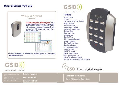
Other products from <strong>GSD</strong><br />
No. 1 Turnpike Business Park,<br />
Ballymount,<br />
Dublin 22, Ireland.<br />
Telephone: +353 1 524 2691.<br />
Fax: +353 1 4430 430.<br />
“Wireless Network<br />
System”<br />
<strong>GSD</strong> Wi-Enterprise/Wi-Plus System is the<br />
next generation in access control solutions.<br />
It provides a Wireless Network throughout<br />
the premises, giving the convenience and<br />
security of a fully networked system for a<br />
fraction of the cost.<br />
For more information on the Wireless Network System visit our website<br />
www.globalsecurity.ie<br />
Installer Name :<br />
Contact Details :<br />
Installation Date :<br />
Features<br />
Controls 1 <strong>Door</strong><br />
50 Users<br />
<strong>Door</strong> Monitoring via <strong>Door</strong> Contact<br />
Tamper Resistant<br />
Easy Programming<br />
Programmable Settings:<br />
- Number of PIN code Digits<br />
- Engineer Code<br />
- Relay Active Time<br />
- <strong>Door</strong> Ajar Time<br />
- <strong>Door</strong> Bell Time<br />
- Silent or Audible Operation<br />
- Duress PIN Codes<br />
- <strong>Door</strong> Toggle Operation<br />
- <strong>Door</strong> Forced Alarm<br />
- Anti-Tail Gate Operation<br />
- <strong>Keypad</strong> Backlight<br />
- Invalid PIN Lockout<br />
- Inputs/Outputs Options<br />
Indoor/Outdoor Use - IP 67<br />
Robust Polycarbonate Housing<br />
Mounts onto Standard Electrical Patress Box<br />
Operation Instruction:<br />
1 door digital keypad<br />
Enter PIN code to Open <strong>Door</strong>
Administration Notes<br />
User Administrator<br />
1<br />
2<br />
3<br />
4<br />
5<br />
6<br />
7<br />
8<br />
9<br />
10<br />
11<br />
12<br />
13<br />
14<br />
15<br />
16<br />
17<br />
18<br />
19<br />
20<br />
21<br />
22<br />
23<br />
24<br />
25<br />
Detach outer pages<br />
and give to end user.<br />
Detach outer pages<br />
and give to end user.<br />
26<br />
27<br />
28<br />
29<br />
30<br />
31<br />
32<br />
33<br />
34<br />
35<br />
36<br />
37<br />
38<br />
39<br />
40<br />
41<br />
42<br />
43<br />
44<br />
45<br />
46<br />
47<br />
48<br />
49<br />
50<br />
Administration Notes<br />
User User Name PIN Number User User Name PIN Number
Other products from <strong>GSD</strong><br />
No. 1 Turnpike Business Park,<br />
Ballymount,<br />
Dublin 22, Ireland.<br />
Telephone: +353 1 524 2691.<br />
Fax: +353 1 4430 430.<br />
“Wireless Network<br />
System”<br />
<strong>GSD</strong> Wi-Enterprise/Wi-Plus System is the<br />
next generation in access control solutions.<br />
It provides a Wireless Network throughout<br />
the premises, giving the convenience and<br />
security of a fully networked system for a<br />
fraction of the cost.<br />
For more information on the Wireless Network System visit our website<br />
www.globalsecurity.ie<br />
Contents<br />
Features<br />
Quick Reference<br />
Operation Instructions<br />
Installation Diagrams<br />
Wiring Diagrams<br />
2<br />
3<br />
4<br />
8<br />
10<br />
1 door digital keypad<br />
Installation & User Manual V2.02
2 Features<br />
Technical Specs<br />
Power Supply 12 - 24V AC or DC<br />
Current consumption 100mA<br />
Current consumption with load (max) 130mA<br />
Relay Contact Rating 5 Amps /240V ac<br />
Operating Temperature - 20 C to +60 C<br />
Moisture Resistance IP 67<br />
Dimensions - Flush Mount W. 87mm D. 21mm H. 119mm<br />
- Surface Mount W. 87mm D. 35mm H. 119mm<br />
Features<br />
Controls 1 <strong>Door</strong><br />
50 Users<br />
<strong>Door</strong> Monitoring via <strong>Door</strong> Contact<br />
Tamper Resistant<br />
Easy Programming<br />
Programmable Settings:<br />
- Number of PIN code Digits<br />
- Engineer Code<br />
- Relay Active Time<br />
- <strong>Door</strong> Ajar Time<br />
- <strong>Door</strong> Bell Time<br />
- Silent or Audible Operation<br />
- Duress PIN Codes<br />
- <strong>Door</strong> Toggle Operation<br />
- <strong>Door</strong> Forced Alarm<br />
- Anti-Tail Gate Operation<br />
- <strong>Keypad</strong> Backlight<br />
- Invalid PIN Lockout<br />
- Inputs/Outputs Options<br />
Indoor/Outdoor Use - IP 67<br />
Robust Polycarbonate Housing<br />
Mounts onto Standard Electrical Patress Box<br />
Quick Reference - Menu Codes<br />
3 Step Quick Setup :<br />
Step 1, Restore Factory Default Settings..<br />
Step 2, Change the Engineer Code..<br />
Step 3, Add a User PIN.<br />
Quick reference<br />
Code Description Default Settings<br />
01 Add a User PIN to <strong>Door</strong> 1 1111<br />
03 Remove a User PIN<br />
10 Change the Number of PIN Digits 4 digit PIN (4,5,6 only)<br />
11 Change the Engineer Code 6666<br />
12 Change the Relay Active Time 5 seconds (0-255)<br />
13 Change the <strong>Door</strong> Ajar Time 30 seconds (2-255)<br />
14 Change the <strong>Door</strong> Bell Time 3 seconds (1-10)<br />
20 Set Silent Operation on/off Off<br />
21 Set Ajar Alarm on/off On<br />
22 Set <strong>Door</strong> Bell on/off On<br />
23 Set Duress codes on/off Off<br />
24 Set Toggle Relay on/off On<br />
25 Set <strong>Door</strong> Forced Alarm on/off On<br />
26 Set Anti-Tail Gate on/off Off<br />
27 Set Constant Backlight on/off On<br />
28 Set Invalid PIN Lockout on/off On (3 Retries)<br />
30 Change the Input and Output Options 0<br />
55 Restore Factory Default Settings<br />
X key then<br />
Engineer<br />
Code + Code = 55 +<br />
X key then<br />
Engineer<br />
Code + Code = 11 +<br />
X key then<br />
Engineer<br />
Code + Code = 01 +<br />
Enter New<br />
Engineer<br />
Code<br />
XXXX<br />
User PIN<br />
+<br />
3
4 Operation Instructions<br />
Factory Default PIN codes<br />
The following PIN codes are the Factory Default Settings:<br />
- The Default Engineer code is ‘6666’<br />
- User PIN ‘1111’<br />
Note: The User PIN ’1111’ is deactivated when the first User PIN is added to<br />
the keypad.<br />
Restoring Factory Settings<br />
Code Description<br />
55 Restore Factory Default Settings<br />
Example:<br />
X key then<br />
Engineer<br />
Code + Code = 55 +<br />
Note: If Engineer Code is lost, Remove the <strong>Security</strong> Caps (see page 9) and<br />
hold down the X key during power-up and enter the default Engineer<br />
Code ‘6666’ immediately.This will restore the factory settings.<br />
Adding User PINs<br />
Code Description<br />
01 Add a Standard User or a Toggle User<br />
Example: To Add User PIN ‘5656'<br />
X key then<br />
Engineer<br />
Code + Code = 01 + PIN = 5656 +<br />
Example: To Add Toggle User PIN ‘1234’<br />
X key then<br />
Engineer<br />
1 = Toggle User<br />
PIN = 1234 1<br />
Code + Code = 01<br />
+ +<br />
Standard User: The <strong>Door</strong> opens for the duration of Relay Active Time.<br />
Toggle User: The <strong>Door</strong> remains open permanently on entering the PIN code.The<br />
<strong>Door</strong> will only close after entering the PIN code a second time. Toggle Relay setting<br />
must be set to ON to enable this feature.<br />
Warning: Do not use a Toggle User with a strike lock as lock will remain active.<br />
Removing User PINs<br />
Code Description<br />
03 Remove any User PIN<br />
Example: To Remove User PIN ‘4545’<br />
Operation Instructions<br />
X key then<br />
Engineer<br />
Code + Code = 03 + PIN = 4545 +<br />
Changing Input/Output Options<br />
Code Description<br />
30 Change the Input and Output Options<br />
Example:<br />
Table 1<br />
0<br />
Default<br />
1<br />
X key then<br />
Engineer<br />
Code + Code = 30 +<br />
<strong>Door</strong> Exit<br />
Button<br />
<strong>Door</strong> Exit<br />
Button<br />
<strong>Door</strong><br />
Contact<br />
<strong>Door</strong><br />
Contact<br />
Alarm/<br />
Buzzer<br />
Follow<br />
Relay<br />
Enter 0-1<br />
Refer to<br />
Table 1<br />
Option Input 1 Input 2 Output 1<br />
Page 8<br />
Page 8<br />
5<br />
Wiring<br />
Diagrams<br />
Follow Relay: OP1 will follow the state of the relay.If the relay is activated then OP1<br />
will also be activated.
6 Operation Instructions<br />
Changing Relay Times and Engineer Codes<br />
Code Description Default Settings<br />
10 Change the Number of PIN Digits 4 digit PIN (4,5,6 only)<br />
11 Change the Engineer Code 6666<br />
12 Change the Relay Active Time 5 seconds (0-255)<br />
13 Change the <strong>Door</strong> Ajar Time 30 seconds (2-255)<br />
14 Change the <strong>Door</strong> Bell Time 3 seconds (1-10)<br />
Note: The Number of PIN digits can not be reduced once a User Pin has<br />
been added.<br />
Example: To Change the Engineer Code.<br />
X key then<br />
Engineer + Code = 11 +<br />
Code<br />
Example: To Change the Relay Active Time to 14 seconds.<br />
X key then<br />
Engineer<br />
Code + Code = 12 +<br />
New<br />
Engineer<br />
Code<br />
14<br />
Seconds<br />
Example: To Change the Relay Active Time to a 200msec pulse (set time = 0 secs)<br />
X key then<br />
Engineer<br />
Code + Code = 12 +<br />
0<br />
Seconds<br />
Number of PIN Digits is the number of digits each User PIN will contain (4 or 5 or 6).The<br />
number can not be reduced once a User PIN has been added. If the number of PIN digits<br />
is increased then add leading Zeros to all existing PIN’s.<br />
E.G if increasing PIN digits from 4 to 5 then existing PIN code ‘1234’ changes to ‘01234’<br />
Relay Active Time is the amount of time the relay will remain active. Entering 0 for the<br />
relay active time will generate a 200millisecond pulse.<br />
Ajar Alarm Time is the amount of time the door can remain open before activating the<br />
alarm.<br />
<strong>Door</strong> Bell Time is the amount of time the alarm/buzzer output will activate when the tick<br />
key is pressed.<br />
+<br />
+<br />
Turning Features ON or OFF<br />
Operation Instructions<br />
Code Description Default Settings<br />
20 Set Silent Operation on/off Off<br />
21 Set Ajar Alarm on/off On<br />
22 Set <strong>Door</strong> Bell on/off On<br />
23 Set Duress codes on/off Off<br />
24 Set Toggle Relay on/off On<br />
25 Set <strong>Door</strong> Forced Alarm on/off On<br />
26 Set Anti-Tail Gate on/off Off<br />
27 Set Constant Backlight on/off On<br />
28 Set Invalid PIN Lockout on/off On (3 Retries)<br />
Note: 0 = Off 1= On<br />
Example: To Set the Backlight to always stay ON.<br />
X key then<br />
Engineer<br />
Code + Code = 27 +<br />
1<br />
(ON)<br />
Example: To Set the Backlight to stay ON for 10 seconds only after a key press...<br />
X key then<br />
Engineer<br />
Code + Code = 27 +<br />
0<br />
(OFF)<br />
Silent Operation - If this option is set, all audible tones are silenced.<br />
Duress Codes - If this option is set, the door will open but the alarm will be activated to<br />
an intruder alarm if the duress PIN code is entered. (A duress PIN code is the code<br />
above the user PIN code<br />
e.g. user code=8888 then duress code=8889).<br />
Toggle Relay - If this option is set, then the door will remain open or closed on each<br />
PIN entry for a Toggle User.<br />
<strong>Door</strong> Forced Alarm – This alarm will activate if the door contact is forced open.<br />
Anti-Tail Gate – If this option is set, the door relay time is shortened to 2 seconds,<br />
after the door contact has opened and then closed.<br />
Constant Backlight – If this option is set, the backlight remains on, otherwise it<br />
will turn on only after a key press and switch off after 10 seconds.<br />
Invalid PIN Lockout – Entering an invalid PIN 3 times will lockout the keypad for<br />
15 seconds. All lights will flash during this time. Turning this feature off reduces the<br />
security of the keypad.<br />
7
8 Installation Diagrams<br />
Surface Mounting<br />
When Surface Mounting the <strong>Keypad</strong><br />
a Surface Mount Collar is required.<br />
- Fix Surface Mount Collar to<br />
wall, ensure arrow is<br />
pointing upwards<br />
After fixing Surface Mount Collar to wall<br />
(as above) and wiring is complete as per<br />
wiring diagrams on pages 10-11, the <strong>Keypad</strong><br />
may then be screwed to Surface<br />
Mount Collar using security<br />
screws provided.<br />
Both <strong>Security</strong> Caps are<br />
then clipped onto keypad<br />
<strong>Security</strong> Caps<br />
To attach <strong>Security</strong> Caps: Simply<br />
align the tabs into holes and push<br />
on until click is heard.<br />
Flush Mounting<br />
Installation Diagrams<br />
<strong>Keypad</strong> is mounted to electrical pattress box using security<br />
screws provided. Both <strong>Security</strong> Caps are<br />
then clipped onto <strong>Keypad</strong>.<br />
To release <strong>Security</strong> Caps push a<br />
screwdriver into slots on the side<br />
and pull forward.<br />
9<br />
To attach <strong>Security</strong> Caps: Simply<br />
align the tabs into holes and push<br />
on until click is heard.
10 Wiring Diagrams<br />
Wiring Diagrams Option 0 Wiring Diagrams Option 1<br />
<strong>Door</strong> MagLock<br />
12V Linear<br />
Power supply<br />
12V<br />
0V<br />
NO<br />
COM<br />
NC<br />
IP1<br />
IP2<br />
OP1<br />
TAMP<br />
TAMP<br />
<strong>Door</strong> Exit Button<br />
0V<br />
0V<br />
<strong>Door</strong><br />
Contact<br />
12V 12V<br />
12 - 24 VAC<br />
12 - 24 VAC<br />
0V 0V<br />
12V<br />
Sounder<br />
<strong>Door</strong> MagLock<br />
Volt Free<br />
Tamper Contacts<br />
1 and 2<br />
12V<br />
0V<br />
NO<br />
COM<br />
NC<br />
Wiring for StrikeLock using 12 - 24VAC supply<br />
0V<br />
Note: All OV shown in the diagram are connected<br />
to OV at the back of the keypad terminal block.<br />
12 - 24 VAC<br />
12 - 24 VAC<br />
12V Linear<br />
Power supply<br />
12V<br />
0V<br />
NO<br />
COM<br />
NC<br />
Volt Free<br />
Tamper Contacts<br />
1 and 2<br />
12V<br />
0V<br />
NO<br />
COM<br />
NC<br />
Wiring for StikeLock only using 12 - 24VAC supply<br />
IP1<br />
IP2<br />
OP1<br />
TAMP<br />
TAMP<br />
0V<br />
Wiring Diagrams<br />
<strong>Door</strong> Exit Button<br />
0V<br />
0V<br />
<strong>Door</strong><br />
Contact<br />
Follow Relay<br />
This OP is active<br />
when the relay is<br />
activated.<br />
Note: All OV shown in the diagram are connected<br />
to OV at the back of the keypad terminal block.<br />
11