Cathodic Protection System Design - Ballast Tanks - Corrpro.Co.UK
Cathodic Protection System Design - Ballast Tanks - Corrpro.Co.UK
Cathodic Protection System Design - Ballast Tanks - Corrpro.Co.UK

You also want an ePaper? Increase the reach of your titles
YUMPU automatically turns print PDFs into web optimized ePapers that Google loves.
Technical Product Information<br />
CATHODIC PROTECTION<br />
<strong>System</strong> <strong>Design</strong><br />
BALLAST TANKS<br />
<strong>Cathodic</strong> protection systems can be designed either by experienced <strong><strong>Co</strong>rrpro</strong> service engineers visiting a vessel or<br />
in the company's design and estimating offices. When necessary, Classification Society approval can be obtained<br />
on an owner's behalf.<br />
In order to design cathodic protection systems, <strong><strong>Co</strong>rrpro</strong> requires the following information.<br />
Actual Wetted Surface Area (WSA)<br />
Which Can Be Calculated from<br />
SHIPS TANKS<br />
Owners' drawings, ie mid-ship section and GA or<br />
capacity plan, steelwork/structural drawings for<br />
peak tanks.<br />
Type and extent of coatings with estimate of<br />
percentage breakdown<br />
Desired system life and percentage time in<br />
ballast<br />
Cargoes to be carried, type of tank (ballast only<br />
or cargo/ ballast)<br />
Any heating coils, their material and whether<br />
they are insulated from the structure<br />
Classification Society approval required<br />
Any special factors?<br />
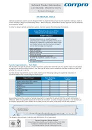
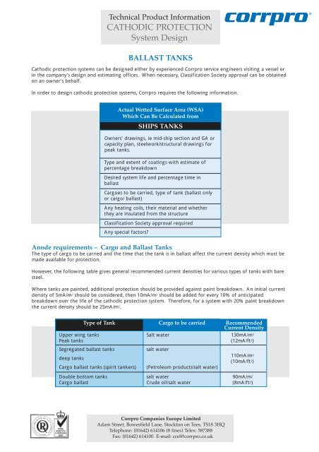
Anode requirements – Cargo and <strong>Ballast</strong> <strong>Tanks</strong><br />
The type of cargo to be carried and the time that the tank is in ballast affect the current density which must be<br />
made available for protection.<br />
However, the following table gives general recommended current densities for various types of tanks with bare<br />
steel.<br />
Where tanks are painted, additional protection should be provided against paint breakdown. An initial current<br />
density of 5mA/m 2 should be considered, then 10mA/m 2 should be added for every 10% of anticipated<br />
breakdown over the life of the cathodic protection system. Therefore, for a system with 20% paint breakdown<br />
the current density should be 25mA/m 2.<br />
Upper wing tanks<br />
Peak tanks<br />
Segregated ballast tanks<br />
deep tanks<br />
Cargo ballast tanks (spirit tankers)<br />
Double bottom tanks<br />
Cargo ballast<br />
Type of Tank Cargo to be carried Recommended<br />
Current Density<br />
Salt water<br />
salt water<br />
(Petroleum products/salt water)<br />
salt water<br />
Crude oil/salt water<br />
<strong><strong>Co</strong>rrpro</strong> <strong>Co</strong>mpanies Europe Limited<br />
Adam Street, Bowesfield Lane, Stockton on Tees, TS18 3HQ<br />
Telephone: (01642) 614106 (8 lines) Telex: 587388<br />
Fax: (01642) 614100 E-mail: ccel@corrpro.co.uk<br />
corrpro ®<br />
130mA/m 2<br />
(12mA/ft 2)<br />
110mA/m 2<br />
(10mA/ft 2)<br />
90mA/m 2<br />
(8mA/ft 2)
Centre tanks<br />
Wing tanks<br />
BALLAST TANKS<br />
Type of Tank Current requirement Recommended<br />
Anode Material<br />
2 /3 in the bottom of the tank<br />
1 /3 in the upper areas<br />
1 /2 in the bottom of the tank<br />
1 /2 throughout the remainder<br />
of the tank<br />
Anode Distribution<br />
Permanent ballast tanks Even distribution over<br />
surface area<br />
Double bottom tanks At least one anode in each<br />
membrane box<br />
Once the number of anodes required has been calculated, their distribution in the tanks must be determined.<br />
The table above gives the rules which should be observed for effective protection against corrosion.<br />
Special note should be taken of the positioning of aluminium anodes in tanks carrying crude oil or petroleum, or<br />
other inflammable products. Certain Classification Societies have restrictions on the height at which these may<br />
be placed because of the potential for a spark to be produced should an anode fall from a defined height. The<br />
Lloyds Register of Shipping, for example, rules that the potential energy of an aluminium or aluminium alloy<br />
anode should not exceed 275J (28kgfm).<br />
Pit-Guard Anodes<br />
Pit-Guard anodes are specially designed to prevent pitting attacks on the bottom shell plating of cargo and<br />
ballast tanks. Lying flat on the bottom shell plating, they provide cathodic protection against corrosion in what<br />
are often deemed to be 'empty' tanks, but which in fact contain residual ballast water that has not been<br />
stripped from the tank. They also provide protection when brine settles out of oil cargoes.<br />
Because residual water remaining in cargo/ballast tanks will be oily, the self-cleaning property of Aloline<br />
aluminium alloys is advantageous in this application.<br />
Pit-Guards are provided with an integral clamp for easy attachment to the scallop holes in the bottom<br />
longitudinals. This means they can be quickly fitted without the need to gas-free for hot work.<br />
Bearing in mind that these anodes are small and may be permanently submerged (while ballast may only be<br />
carried for 40 or 50% of the time), Pit-Guards should be inspected regularly and replaced promptly when<br />
necessary.<br />
Installation Drawings<br />
Plans showing anode layout, traced from owners' drawings, are provided free of charge when anodes are<br />
supplied.<br />
<strong><strong>Co</strong>rrpro</strong> <strong>Co</strong>mpanies Europe Limited<br />
Adam Street, Bowesfield Lane, Stockton on Tees, TS18 3HQ<br />
Telephone: (01642) 614106 (8 lines) Telex: 587388<br />
Fax: (01642) 614100 E-mail: ccel@corrpro.co.uk<br />
Aluminium<br />
and/or zinc<br />
Aluminium<br />
and/or zinc<br />
Aluminium<br />
and/or zinc<br />
Aluminium<br />
and/or zinc