Alpha Uncooled Microbolometer Camera - Flir Systems
Alpha Uncooled Microbolometer Camera - Flir Systems
Alpha Uncooled Microbolometer Camera - Flir Systems

You also want an ePaper? Increase the reach of your titles
YUMPU automatically turns print PDFs into web optimized ePapers that Google loves.
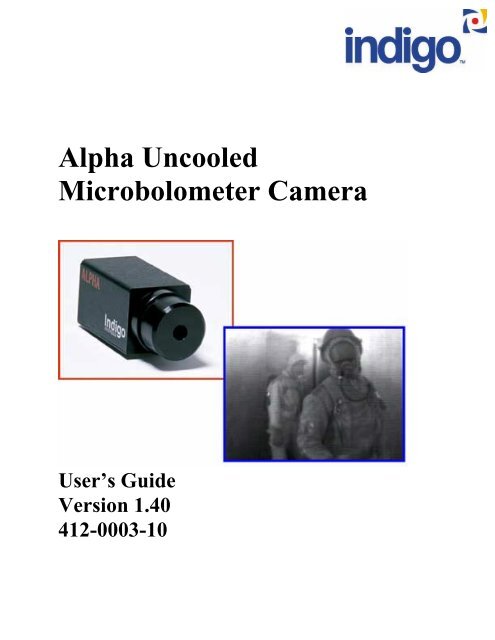
<strong>Alpha</strong> <strong>Uncooled</strong><br />
<strong>Microbolometer</strong> <strong>Camera</strong><br />
User’s Guide<br />
Version 1.40<br />
412-0003-10
<strong>Alpha</strong> User’s Guide 412-0003-10 Version 1.40<br />
TABLE OF CONTENTS<br />
1 INTRODUCTION............................................................................................................... 5<br />
2 ALPHA SPECIFICATIONS.............................................................................................. 5<br />
3 UNPACKING YOUR ALPHA CAMERA........................................................................ 6<br />
4 OPTIONAL FEATURES AND ACCESSORIES ............................................................ 6<br />
5 BASIC OPERATION ......................................................................................................... 7<br />
6 ELECTRICAL INTERFACE............................................................................................ 8<br />
6.1 POWER INPUT ................................................................................................................. 8<br />
6.2 VIDEO OUTPUT............................................................................................................... 8<br />
6.3 AUXILIARY I/O CONNECTOR.......................................................................................... 8<br />
7 REMOTE CAMERA CONTROL..................................................................................... 9<br />
7.1 INSTALLATION OF ALPHA CONTROL PANEL SOFTWARE.................................................. 9<br />
7.2 CONNECTING THE ALPHA TO A COMPUTER................................................................... 10<br />
7.3 PALM PILOT OPERATION .............................................................................................. 10<br />
7.4 OPERATION OF THE ALPHA CONTROL PANEL (GRAPHICAL USER INTERFACE) ON A PC 10<br />
7.5 CONTROL PANEL FEATURES......................................................................................... 11<br />
7.5.1 NUC..................................................................................................................... 11<br />
7.5.2 Video Display ...................................................................................................... 11<br />
7.5.3 Digital Output ..................................................................................................... 14<br />
7.5.4 Diagnostics.......................................................................................................... 14<br />
8 ALPHA SYSTEMS INTEGRATION AND INTERFACING ...................................... 14<br />
8.1 CAMERA POWER DISSIPATION...................................................................................... 15<br />
8.2 AUXILIARY I/O CONNECTOR......................................................................................... 15<br />
8.3 VIDEO OUTPUT............................................................................................................. 15<br />
8.4 POWER INPUT ............................................................................................................... 16<br />
8.5 REAL-TIME DIGITAL DATA OUTPUT............................................................................. 16<br />
8.6 DATA SYNCHRONIZATION ............................................................................................ 16<br />
8.7 DIGITAL DATA FORMAT ............................................................................................... 16<br />
8.8 TELEMETRY DATA........................................................................................................ 16<br />
8.9 FPA DATA ................................................................................................................... 17<br />
8.10 SERIAL COMMUNICATIONS........................................................................................... 17<br />
9 ELECTRICAL INTERFACE.......................................................................................... 23<br />
9.1 CAMERA POWER CONNECTOR...................................................................................... 23<br />
9.2 CAMERA VIDEO CONNECTOR....................................................................................... 23<br />
9.3 AUXILIARY I/O CONNECTOR........................................................................................ 24<br />
10 OPTO-MECHANICAL INTERFACE ........................................................................... 24<br />
2
<strong>Alpha</strong> User’s Guide 412-0003-10 Version 1.40<br />
APPENDIX A ALPHA DIGITAL INTERFACE (ADI)...................................................... 28<br />
APPENDIX B INTELLIGENT ACCESSORY SHOE (HOT SHOE)............................... 35<br />
3
<strong>Alpha</strong> User’s Guide 412-0003-10 Version 1.40<br />
Cautions and Warnings:<br />
• Do not image very high intensity radiation sources, such as the sun, carbon dioxide lasers,<br />
arc welders, etc.<br />
• The camera is not sealed, so avoid dust and moisture exposure, and replace lens cap when<br />
not in use.<br />
• Do not exceed 30 volts DC input power, or reverse the polarity of input power.<br />
• Do not apply DC input power to both the DC input and the Auxiliary I/O connector<br />
simultaneously.<br />
• The battery pack accessory is uncharged. Charge for 6 hours prior to use.<br />
• This is a precision optical instrument, and should be protected from shock and vibration.<br />
Keep the camera stored in the manufacturer’s shipping container.<br />
• This camera contains static-sensitive electronics and should be handled appropriately.<br />
• Do not open the camera body, as doing so will void the warranty.<br />
• Do not insert any objects inside the lens housing, as the calibration flag and/or lens can be<br />
damaged.<br />
• If you have questions that are not covered in this manual, or need service, contact<br />
Customer Support at 805-964-9797 for additional information (prior to returning<br />
cameras).<br />
4
<strong>Alpha</strong> User’s Guide 412-0003-10 Version 1.40<br />
1 INTRODUCTION<br />
ALPHA is a long-wavelength (7.5 – 13.5 microns) uncooled microbolometer camera designed for<br />
applications that demand absolute minimum size, weight, and power consumption. A germanium<br />
single-element, 11mm focal length lens (40° x 30° field of view) is provided with ALPHA (unless<br />
otherwise specified). The camera may be operated by remote control through a serial command<br />
interface. ALPHA provides analog RS-170A or CCIR as a factory configured option, and real-time<br />
12-bit corrected digital video. Images generated by the camera are displayed at 30 frames per<br />
second (25 FPS in CCIR). Lens options are available.<br />
This manual is organized in increasing levels of detail to provide information for all levels of<br />
user. The first level is for the user who wants to use the analog video output only and leaves the<br />
camera in its factory default settings. The next level is intended for the system integrator who<br />
wants to control the camera functions through the Graphical User Interface (GUI) or with<br />
commands sent through the RS-232 interface. The last level is for the OEM user who desires<br />
control of the camera functions in addition to the raw digital image data.<br />
2 ALPHA SPECIFICATIONS<br />
• 160 (H) x 128 (V) uncooled microbolometer sensor array, 51 x 51 micron pixels<br />
• Optical Fill Factor: 65%<br />
• 40° horizontal FOV, 11 mm focal length lens, f/1.6 aperture<br />
• Thermoelectric sensor stabilization<br />
• Input power range: 5.0–30 VDC<br />
• Power Consumption: 1.5 Watts RMS nominal at room temperature (2.5 W RMS<br />
nominal at temperature limits) [1]<br />
• Operating Temperature Range: 0° C to 55° C conduction, 0° C to 49° C still air<br />
• Humidity: 95% non-condensing<br />
• Dimensions: 1.7" H x 1.7" W x 4.3" L (including 40° lens)<br />
• Weight: < 200 grams<br />
• Analog video outputs: RS-170A (CCIR optional)<br />
• Digital video output: Proprietary real-time, 12-Bit, pixel replaced, normalized, nibble<br />
serialized<br />
• Remote interface: Proprietary serial command interface<br />
[1] For peak power, add power in Watts equal to 0.5 Amps multiplied by the input supply<br />
voltage when shutter closes. This extra power is consumed for a 0.5 second duration.<br />
Note: These specifications are subject to change without notice.<br />
5
<strong>Alpha</strong> User’s Guide 412-0003-10 Version 1.40<br />
3 UNPACKING YOUR ALPHA CAMERA<br />
For end user customers (not OEM customers), the following items come standard in your <strong>Alpha</strong><br />
<strong>Camera</strong> package:<br />
1. 110/220V AC/DC converter with Cable<br />
2. RCA Video Cable<br />
3. Lens Cap<br />
4. Tripod Adapter<br />
5. Serial Cable: <strong>Camera</strong> to PC Serial Port<br />
6. Software (PC)<br />
7. Carrying/Transport case<br />
8. User’s Guide<br />
9. Packing List/Contract Terms Sheet<br />
If there is any discrepancy between the above list and the contents of your camera package, please<br />
contact Indigo <strong>Systems</strong> Customer Support immediately.<br />
4 OPTIONAL FEATURES AND ACCESSORIES<br />
• CCIR video format factory configured<br />
• 11° V x 15° H Lens [2]<br />
• 20° V x 25° H lens [2]<br />
• <strong>Alpha</strong> Digital Interface (ADI) Unit<br />
• <strong>Alpha</strong> ThermoCordeR interface (Hot-shoe)<br />
• Battery Pack (Note: battery is sent uncharged. Charge for 6 hours prior to use.)<br />
• Self-Contained Button Panel (Palm Pilot) with cable and adapter<br />
[2] Lenses must be ordered with the camera and are not interchangeable.<br />
6
<strong>Alpha</strong> User’s Guide 412-0003-10 Version 1.40<br />
5 BASIC OPERATION<br />
Note: If you are using the <strong>Alpha</strong> Digital Interface (ADI) with your <strong>Alpha</strong> camera, please see the<br />
ADI Manual Appendix A for setup instructions.<br />
1. Attach the tripod adapter plate to the bottom of your <strong>Alpha</strong> camera using the hardware<br />
provided if you intend to mount the camera on a tripod.<br />
2. Remove the lens cap, and be sure to replace when the camera is not in use to prevent lens<br />
contamination by dust and other materials.<br />
3. Connect the VIDEO OUT port on the back of your camera to an unterminated monitor<br />
input using the RCA-RCA cable provided. The <strong>Alpha</strong> will not work with a terminated<br />
monitor. See Figure 1 below.<br />
4. Connect the power supply provided to the DC POWER input connector on the back of<br />
the camera.<br />
Note: The voltage range is 5.0-30 VDC. The center pin of the power input connector is<br />
positive.If you apply a voltage exceeding 30 volts, or you reverse the polarity of the input<br />
power to your <strong>Alpha</strong> camera, you will cause damage requiring factory service.<br />
Figure 1. <strong>Alpha</strong> Back Panel<br />
5. The camera will produce a startup screen immediately upon application of power.<br />
6. The camera will take ~15 seconds to produce an image after power up, as the sensor<br />
achieves temperature stability (at which point the startup screen will disappear). The start<br />
time is a function of ambient temperature, and increases for temperatures above or below<br />
25 C.<br />
7. The camera will automatically perform a 1-point correction at periodic intervals or<br />
whenever the camera case temperature changes by 0.5 degrees C. During this time the<br />
image will be frozen for less than 1 second. This feature can be disabled via the<br />
command interface. A one-point correction can be initiated at any time through the<br />
command interface.<br />
7
<strong>Alpha</strong> User’s Guide 412-0003-10 Version 1.40<br />
8. The AGC (Automatic Gain Control) is always enabled, and will adjust the image<br />
brightness and contrast automatically.<br />
6 ELECTRICAL INTERFACE<br />
The <strong>Alpha</strong> camera is provided with standard connectors for video output and power input, but all<br />
camera inputs and outputs are additionally routed through the AUX I/O connector. However,<br />
care should be taken to use one or the other connector for power input to the camera, not both<br />
simultaneously. Damage to the camera can result if DC power is applied through both<br />
connectors.<br />
6.1 Power Input<br />
The <strong>Alpha</strong> camera is provided with a “power mouse” transformer that converts 110 VAC or 220<br />
VAC to 6 VDC for the input power. If you prefer to provide your own power supply for the<br />
camera (a battery pack, for example), please follow the guidelines in Section 9.1.<br />
6.2 Video Output<br />
The video output of the <strong>Alpha</strong> camera is factory configured for either RS-170A or CCIR video<br />
formats. The camera video output connector is a standard RCA type jack. The center pin is the<br />
video output and the sleeve is the video return. The video output of the <strong>Alpha</strong> camera is factory<br />
configured for either RS-170A or CCIR video formats. The load should be unterminated (high<br />
impedance input).<br />
Note: For best camera performance, do not connect the video return to either the power return<br />
or the digital return when using the Aux I/O connector.<br />
6.3 Auxiliary I/O Connector<br />
The camera Auxiliary I/O connector (shown in Figure 2 with a mating cable) contains input<br />
power, video output, serial communications, digital data and data synchronization outputs. A<br />
number of digital grounds are included as return paths for each digital input/output. The digital<br />
grounds should be connected together at the receiver, however, for best noise performance, the<br />
digital grounds should be isolated from the input power return (IOPWRRTN) and video return.<br />
See Section 8.2 for the <strong>Alpha</strong> camera Auxiliary I/O connector pinout. Some users may wish to<br />
use this connector exclusively, since every camera function and input/output is routed through it,<br />
eliminating the need for multiple connectors.<br />
Note: Do not apply power to the DC input connector and the Auxiliary I/O connector<br />
simultaneously.<br />
8
<strong>Alpha</strong> User’s Guide 412-0003-10 Version 1.40<br />
Figure 2. <strong>Alpha</strong> <strong>Camera</strong> with Auxiliary I/O Cable<br />
7 REMOTE CAMERA CONTROL<br />
Note: The camera will always go to the default settings when powered up, thus any changes to<br />
the camera settings are lost when the camera is power-cycled.<br />
The <strong>Alpha</strong> is designed to be controllable through an RS-232 serial interface. A PC-based<br />
application is provided that enables the user to change parameters of the camera through a<br />
graphical user interface called the <strong>Alpha</strong> Control Panel. This application can be run on any<br />
Windows 95, 98 or NT-based computer. Additionally, a remote button panel accessory based on<br />
the Palm Pilot is available as an option. The Palm Pilot comes with the <strong>Alpha</strong> Control Panel<br />
software installed, and enables the user to easily control the camera in field applications.<br />
More advanced users can send ASCII commands to the camera from a terminal emulator<br />
program such as HyperTerminal, or write their own software to transmit ASCII commands.<br />
Currently the <strong>Alpha</strong> camera is not designed to transmit data out of the serial command port.<br />
The procedure for controlling the camera with a PC is as follows:<br />
1. Install <strong>Alpha</strong> PC Control Panel software on the host computer.<br />
2. Connect the cable between the PC serial port and the camera.<br />
3. Run the <strong>Alpha</strong> software and control the camera.<br />
7.1 Installation of <strong>Alpha</strong> Control Panel Software<br />
The following procedure should be followed for installing the <strong>Alpha</strong> Control Panel Software.<br />
• Insert the CD marked <strong>Alpha</strong> Control Panel Install Disk into your CD-ROM drive, and<br />
run the .exe program. You can do this by browsing to the CD-ROM using Windows<br />
Explorer, or on your Windows start menu, select “Run” and then either type in<br />
“D:\setup.exe”, or use the browse button to select and execute this file.<br />
9
<strong>Alpha</strong> User’s Guide 412-0003-10 Version 1.40<br />
• The installation program will present instructions for installing the application to your<br />
hard drive. By default, the setup wizard will install the application in the directory<br />
C:\ProgramFiles\<strong>Alpha</strong>, and the shortcut to the application will go into the program<br />
group Indigo.<br />
7.2 Connecting the <strong>Alpha</strong> to a Computer<br />
Attach the serial data cable that is included with your <strong>Alpha</strong> camera to the Aux I/O connector on<br />
the back of the camera, as shown in Figure 3. Attach the other end (the one with the 9 pin<br />
connector) to an unused serial port on the back of your computer. These ports are usually labeled<br />
COM1 and COM2. Serial communication to the camera is accomplished using a RS-232<br />
command protocol. The receive channel on the <strong>Alpha</strong> camera will accept normal RS-232 signal<br />
levels. The com port setting should be 9600 Baud, no parity, 8 data bits and 1 stop bit.<br />
Connect<br />
this end to<br />
computer<br />
Figure 3. <strong>Alpha</strong> <strong>Camera</strong> with Serial Cable Attached<br />
7.3 Palm Pilot Operation<br />
The Palm Pilot accessory is a small palmtop computer, which can be used as a button panel<br />
interface for applications that require a camera controller of minimal weight and size. To use the<br />
Palm Pilot for camera control, you must connect it to your <strong>Alpha</strong> camera using the cable and<br />
adapter included with the Palm Pilot. The Palm Pilot comes with a Quick Start card. Follow the<br />
instructions contained on that card to install the batteries and bring up the “desktop” screen of the<br />
Pilot. Under the Start menu, go to Programs, and then select <strong>Alpha</strong> Control Panel. The Control<br />
Panel is then operated in the same way as through the PC-based control panel, except that the<br />
buttons are activated with a stylus that is included with the Palm Pilot. Follow the instructions in<br />
the following sections to control your <strong>Alpha</strong> camera.<br />
7.4 Operation of the <strong>Alpha</strong> Control Panel (Graphical User Interface) on a PC<br />
After you have installed your <strong>Alpha</strong> Control Panel software, start the software by double-clicking<br />
on the <strong>Alpha</strong> icon. The following window (shown in Figure 4) will appear on your screen,<br />
prompting you to select a COM port for the <strong>Alpha</strong>. In this particular case, COM2 is the only port<br />
available, as the others are in use (that is why they appear “grayed out”). To select the port, click<br />
on the “radio button” and then hit return, or press OK.<br />
10
<strong>Alpha</strong> User’s Guide 412-0003-10 Version 1.40<br />
Click here<br />
to select<br />
COM2<br />
Figure 4. Com Window<br />
You should see the Control Panel window appear. The control panel has two menu options and<br />
three tabs. The menus are File and Options. The File menu contains one item, Exit, which exits<br />
you from the Control Panel application. This can also be accomplished with the command<br />
Ctrl+X. The Options menu contains the Com Port command, which brings up the Com port<br />
selection screen (Ctrl+C also does this), and an About command, which tells you the version of<br />
the Control Panel software you are running (Ctrl+A).<br />
7.5 Control Panel Features<br />
7.5.1 NUC<br />
The NUC display box is on the right side of the control panel, shown in Figures 5 and 6. It<br />
contains two controls for the NUC, or Non-Uniformity Correction, which is required to correct<br />
for differences between detector elements in a microbolometer array. The FFC (Flat-Field<br />
Correction) button manually initiates a flat-field correction (also known as a 1-point correction).<br />
When the user presses this button, a small calibration flag moves into position over the lens and<br />
presents a field of uniform temperature to the detector elements. The camera then calculates<br />
offset coefficients for each detector on the assumption that each pixel is being illuminated with<br />
exactly the same amount of IR energy by the flag. This flat-field correction will also take place<br />
automatically whenever the camera temperature changes by 0.5 degrees C, or every two minutes.<br />
When the FFC correction is taking place, the video image is frozen on the monitor for less than 1<br />
second. The Auto FFC checkbox allows the camera to automatically perform a flat-field<br />
correction when the button is selected. In situations where the video image cannot be allowed to<br />
freeze for even a fraction of a second, deselecting the Auto FFC button can disable this feature.<br />
The box is checked by default (upon power up).<br />
7.5.2 Video Display<br />
The Video Display box controls the analog video output from the camera. There are two options<br />
for the brightness and contrast control type. The default option is a histogram automatic gain<br />
control (AGC), indicated by the word “Histogram” in the pull-down menu in the upper right<br />
11
<strong>Alpha</strong> User’s Guide 412-0003-10 Version 1.40<br />
corner of the video display box. This window is shown in Figure 5. There is a slider in the upper<br />
left part of the Video Display box that controls the gain for the AGC. It is adjustable from 0 to<br />
255. The value is displayed in the AGC gain entry box below the slider, and can also be<br />
manually entered. The top pull-down menu in the upper right part of the Video Display box also<br />
has a “Manual” option. This option allows the user to manually set the brightness and contrast<br />
of the video display. This is very useful if these values need to be fixed at specific levels in order<br />
to bring out a specific feature in the scene being imaged. The window shown in Figure 6 shows<br />
the changes in the window when the manual setting is chosen. There are now two sliders in the<br />
Video Display box, one that controls brightness and the other that controls contrast, along with<br />
dialogue boxes below each slider that enable the user to input specific values. The values shown<br />
are the defaults: Brightness = 2048, Contrast = 128. The two parameters are adjustable from 0 to<br />
4095 and 0-255 respectively.<br />
The video display box has two additional pull-down menus. The first menu has the two possible<br />
polarity settings, white-hot and black-hot video. The factory default setting is White-Hot, i.e.<br />
hot objects appear whiter than cold objects. The other menu in the video display box enables the<br />
user to control whether the image is Normal (right side up), Inverted (upside-down), Reverted<br />
(column order flipped, like a mirror image) or both Inverted and Reverted. These choices are<br />
available for situations where the camera must be mounted upside down or a special inverting or<br />
reverting optic is used. The factory default setting is Normal, which means that the image on a<br />
monitor is oriented normally with respect to the camera body.<br />
The Freeze checkbox freezes the video image on the screen when checked. Deselecting the box<br />
returns the camera to normal streaming video output. The Freeze is unchecked by default. The<br />
Enabled checkbox enables the video output, and this box is checked by default when the camera<br />
is powered up. Deselecting the box disables the analog video, thus conserving power for<br />
applications where power consumption is critical and only the digital video output is used.<br />
12
<strong>Alpha</strong> User’s Guide 412-0003-10 Version 1.40<br />
Slider controls<br />
AGC Gain<br />
Automatic Flat Field<br />
Correction when selected<br />
Default is<br />
Digital Data<br />
Post-NUC<br />
Check this box to<br />
enable digital data<br />
Options are:<br />
Disabled,<br />
Input Test,<br />
Encoder Test<br />
Command Entry<br />
box (see Table 3 for<br />
command list)<br />
Sends command entered<br />
in box to left of button<br />
Figure 5. Histogram AGC Control Panel Window<br />
13<br />
AGC Gain<br />
Entry Box<br />
Options are Histogram<br />
AGC or Manual<br />
Brightness/Contrast<br />
Options are<br />
White-Hot or<br />
Black-Hot<br />
Options are Normal,<br />
Invert, Revert, and<br />
Invert/Revert<br />
Freeze Video when selected<br />
Enable Video when selected<br />
Flat-Field<br />
Correction<br />
Button<br />
Auto FFC when<br />
selected (default)
<strong>Alpha</strong> User’s Guide 412-0003-10 Version 1.40<br />
Brightness<br />
Slider and<br />
Input Box<br />
Contrast<br />
Slider and<br />
Input Box<br />
Figure 6. Manual Brightness/Contrast Control Panel Window<br />
7.5.3 Digital Output<br />
The Digital Output dialog box has a pull-down menu that controls whether the data has had a<br />
Non-Uniformity Correction (NUC) applied to it. The data is available as Post-NUC (corrected)<br />
the default setting, or Pre-NUC (uncorrected)., The Pre-NUC option is for cases where the user<br />
wants to apply an external NUC using image-processing software. The Enabled checkbox<br />
enables or disables the digital data output. It is checked by default (digital output enabled).<br />
7.5.4 Diagnostics<br />
The Diagnostics dialog box contains a pull-down menu to make the diagnostic mode Disabled,<br />
or enable either the Input Test or the Encoder Test. The Input test substitutes a 0-4096 bit data<br />
ramp for the FPA output. This is intended for diagnostics at the factory. The Encoder Test<br />
creates a test pattern whereby each successive column from left to right is set to gray scale values<br />
from 0 to 255. At column 256, the gray scale resets back to 0. This enables the user to adjust the<br />
video monitor so that the “black” columns (low number) are just barely black, and the “white”<br />
columns (high numbers) have just a trace of gray in them. The Command Entry box enables<br />
the user to send commands to the camera by typing them into the box, then pressing the Send<br />
button. The commands are listed in Table 3.<br />
8 ALPHA SYSTEMS INTEGRATION AND INTERFACING<br />
Some users will want to go beyond the scope of the <strong>Alpha</strong> Control Panel software and write their<br />
own applications that will control the camera via the RS-232 interface. This section gives the<br />
user the interface information required to communicate with the <strong>Alpha</strong> camera. This section also<br />
describes the electro-mechanical interfaces of the <strong>Alpha</strong> camera. It includes information<br />
14
<strong>Alpha</strong> User’s Guide 412-0003-10 Version 1.40<br />
regarding optical, mechanical and connector locations with respect to the camera mounting<br />
features. A description of the electrical connections is also provided. Some of the information in<br />
this section is a repeat of earlier sections of this manual, but this section goes into more detail for<br />
the OEM user.<br />
8.1 <strong>Camera</strong> Power Dissipation<br />
The power dissipation of the camera is a function of the ambient temperature of the camera (due<br />
to the TE cooler/heater). The nominal power dissipation is 1.5 watts average (25° C ambient<br />
temperature) and increases to 2.5 watts average at the ambient temperature limits. To calculate<br />
the peak power of the camera, add the shutter drive power to the average camera power. The<br />
shutter drive power is found by multiplying the input voltage by 0.5 amps. The duration of the<br />
shutter drive pulse is 0.5 seconds. The following is an example camera power calculation:<br />
Input voltage = 6 V;<br />
Shutter drive power: 6V x 0.5A = 3 watts;<br />
<strong>Camera</strong> power: 3 + 1.5 = 4.5 watts peak (at 25 C ambient temperature)<br />
The camera base is the thermal rejection surface and must be held within the ambient<br />
temperature limits for proper operation. The temperature limits for the <strong>Alpha</strong> camera are 0° C to<br />
55° C.<br />
Note: The maximum ambient temperature when the camera is operated in still air should<br />
be derated by 6° C.<br />
8.2 Auxiliary I/O connector<br />
The camera Auxiliary I/O connector contains input power, video output, serial communications,<br />
digital data and data synchronization outputs. A number of digital signal grounds are included as<br />
return paths for each digital input/output. The digital signal grounds should be connected<br />
together at the receiver, however, for best noise performance, the digital signal grounds should be<br />
isolated from the input power return (IOPWRRTN) and video ground (Video Gnd). A separate<br />
coaxial cable for the video signal (Video) and video return (Video Gnd) is recommend for best<br />
performance. See Table 1 for the <strong>Alpha</strong> camera Auxiliary I/O connector signal positions. The<br />
backshell of the Auxiliary I/O connector is connected to the camera chassis.<br />
Note: Do not connect power to both the auxiliary and power input connectors<br />
simultaneously.<br />
8.3 Video Output<br />
The video output of the <strong>Alpha</strong> camera is factory configured for either RS-170A or CCIR video<br />
formats. A high impedance (HI-Z) termination is required at the load.<br />
Note: For best camera performance, do not connect the video return to either the power return<br />
or the digital return.<br />
15
<strong>Alpha</strong> User’s Guide 412-0003-10 Version 1.40<br />
8.4 Power Input<br />
The power input to the <strong>Alpha</strong> camera is nominally 6 volts DC but the camera will operate over a<br />
range of 5.0 VDC (minimum) to 30 VDC (maximum). For best performance, the ripple on the<br />
power input should be less than 100mV peak-to-peak (DC to 10 MHz).<br />
8.5 Real-Time Digital Data Output<br />
The <strong>Alpha</strong> camera will output real-time, 12-bit digital data from the Auxiliary I/O connector. The<br />
digital data bus output and timing are enabled at camera start-up. The digital data stream includes<br />
camera telemetry and FPA data. The FPA data may be represented as either pre-NUC (on<br />
command – no NUC processing applied to the data) or post-NUC (default – NUC processing<br />
applied to data). The camera digital output can be disabled (via serial command) to reduce power<br />
consumption. See Section 7.5.3.<br />
8.6 Data Synchronization<br />
The <strong>Alpha</strong> camera generates three synchronization signals. The DATA FRAME signal is a<br />
synchronization pulse issued once per frame time with duration of one DATACLOCK pulse<br />
width. The DATA FRAME signal should be captured using the rising edge of the<br />
DATACLOCK. The DATA VALID signal is asserted when valid data is present on the digital<br />
output and is synchronous with the rising edge of DATACLOCK. The falling edge of DATA<br />
CLOCK is used to latch the data. The DATACLOCK frequency is determined by the video<br />
configuration of the camera. The DATACLOCK frequency is 12.27 MHz in RS-170A video<br />
configuration and 14.75 MHz in CCIR mode. Figure 7 shows the relationship between the data<br />
and the synchronization signals.<br />
8.7 Digital Data Format<br />
The digital data output from the camera consists of 4-bit wide nibbles generated at the DATA<br />
CLOCK rate. Each nibble of data should be latched using the falling edge of the DATA CLOCK.<br />
Four nibbles are needed to reconstruct each 12-bit word. The first nibble (A) contains the least<br />
significant bits, the second nibble (B) contains the middle bits and the third nibble (C) contains<br />
the most significant bits of the reconstructed word. The fourth nibble (D) is always held low. The<br />
digital data is output in groups of 8 words (4 nibbles per word) and a reference word. The first 20<br />
groups (0 to 19) represent the camera telemetry data. The remaining groups represent the FPA<br />
pixel and group reference data. Figure 8 depicts the data output format and timing<br />
8.8 Telemetry Data<br />
The <strong>Alpha</strong> camera outputs telemetry information each frame period. The telemetry information is<br />
used to support factory calibration processes. The telemetry information consists of various<br />
camera operational parameters and occupies the first 20 groups (output words 0 to 159) in the<br />
digital data stream and replaces the pixel data from the first physical row of the array. A detailed<br />
description of the telemetry data format is found in Table 2.<br />
Note: The reference data has no relationship to the telemetry data.<br />
16
<strong>Alpha</strong> User’s Guide 412-0003-10 Version 1.40<br />
8.9 FPA Data<br />
The <strong>Alpha</strong> camera also outputs FPA pixel value and group reference data. The data is output in<br />
groups that include a reference and 8 pixels. In pre-NUC output mode, the group reference data<br />
can be subtracted from the 8 pixels that follow to improve the common-mode noise performance.<br />
The first group of pixel data is found in the group number 20 (output word number 160). The<br />
first group of pixel data represents the first 8 pixels from the second row of the physical array<br />
(pixel coordinates row 1, columns 0 through 7). The data for pixels in the first physical row (row<br />
0) is not available. Subsequent groups of data are in a raster type pattern (i.e. group # 21 contains<br />
pixels from row 1, columns 8 through 15; group # 22 contains pixels from row 1, columns 16<br />
through 23). The total number of rows in the output is a function of the video format. For RS-170<br />
video format, the number of rows is 119 while the number of rows for CCIR video format is 127.<br />
Note: the group reference data output precedes the DATA VALID signal as shown in Figure 8.<br />
8.10 Serial Communications<br />
Serial communication to the camera is accomplished using a RS-232 command protocol. The<br />
receive channel will accept normal RS-232 signal levels. The transmit channel is currently nonfunctional.<br />
See Table 3 for a list of commands.<br />
17
<strong>Alpha</strong> User’s Guide 412-0003-10 Version 1.40<br />
Pin # Signal Name Description<br />
1 Video RS-170A or CCIR video output<br />
2 Tx[3V] RS-232 transmit, 3 volt levels<br />
3 Rx[3V] RS-232 receive, 3 volt levels<br />
4 - Unused<br />
5 - Unused<br />
6 Data Frame Frame synchronization output, 3 volt level<br />
7 Data Valid Data valid output, 3 volt level<br />
8 Data Clock Pixel clock output, 3 volt level<br />
9 Data0 Real-time digital data output, bit 0<br />
10 Data1 Real-time digital data output, bit 1<br />
11 Data2 Real-time digital data output, bit 2<br />
12 Data3 Real-time digital data output, bit 3<br />
13 IOPWR <strong>Camera</strong> input power, 5 volt nominal<br />
14 Video Gnd RS-170A or CCIR video return<br />
15 Dgnd Ground, return for Tx<br />
16 Dgnd Ground, return for Rx<br />
17 Dgnd Ground, return for SyncFrame<br />
18 Dgnd Ground, return for SyncClock<br />
19 Dgnd Ground, return for Data Frame<br />
20 Dgnd Ground, return for Data Valid<br />
21 Dgnd Ground, return for Data Clock<br />
22 Dgnd Ground, return for Data output bit 0<br />
23 Dgnd Ground, return for Data output bit 1<br />
24 Dgnd Ground, return for Data output bit 2<br />
25 Dgnd Ground, return for Data output bit 3<br />
26 IOPWRRTN <strong>Camera</strong> power return<br />
Table 1. Auxiliary I/O Connector<br />
18
<strong>Alpha</strong> User’s Guide 412-0003-10 Version 1.40<br />
Parameter Word<br />
Location<br />
Nibble A Nibble B Nibble C Nibble D<br />
0 1 2 3 0 1 2 3 0 1 2 4 0 1 2 3<br />
FPA temperature 0 0 1 2 3 4 5 6 7 8 9 10 11 L L L L<br />
1 12 13 X X X X X X X X X X L L L L<br />
Chassis<br />
Temperature<br />
2 0 1 2 3 4 5 6 7 8 9 10 11 L L L L<br />
3 12 13 X X X X X X X X X X L L L L<br />
Chassis temp low<br />
threshold<br />
Chassis temp<br />
high threshold<br />
Table switch data<br />
threshold<br />
Population below<br />
data threshold<br />
Population above<br />
data threshold<br />
Active calibration<br />
table<br />
4 0 1 2 3 4 5 6 7 8 9 10 11 L L L L<br />
5 12 13 X X X X X X X X X X L L L L<br />
6 0 1 2 3 4 5 6 7 8 9 10 11 L L L L<br />
7 12 13 X X X X X X X X X X L L L L<br />
8 0 1 2 3 4 5 6 7 8 9 10 11 L L L L<br />
9 X X X X X X X X X X X X L L L L<br />
10 0 1 2 3 4 5 6 7 8 9 10 11 L L L L<br />
11 12 13 14 15 X X X X X X X X L L L L<br />
12 0 1 2 3 4 5 6 7 8 9 10 11 L L L L<br />
13 12 13 14 15 X X X X X X X X L L L L<br />
14 0 1 2 3 4 5 6 7 X X X X L L L L<br />
15 X X X X X X X X X X X X L L L L<br />
Reserved 16 - 159 H H H H H H H H H H H H L L L L<br />
Table 2. Telemetry data description<br />
19
<strong>Alpha</strong> User’s Guide 412-0003-10 Version 1.40<br />
Name Description Cmd Argument Default Reply<br />
VIDEO_DISPLAY Enables or disables the<br />
video output<br />
d 0=disable, 1=enable 1 > if ok, ? Otherwise<br />
VIDEO_DISPLAY_POLARITY Sets the video display<br />
polarity<br />
VIDEO_DISPLAY_ORIENTATION Sets the video display<br />
polarity<br />
FREEZE_FRAME Freezes the video<br />
display<br />
DIGITAL_OUTPUT Enables or disables the<br />
digital output<br />
DIGITAL_OUTPUT_TAP Sets the digital output<br />
tap point<br />
AGC Selects the automatic<br />
gain corrector mode<br />
CONTROL_BITS Sets the state of<br />
various control bits<br />
HISTOGRAM_CLIP_VALUE Sets the histogram AGC<br />
clipping value<br />
HISTOGRAM_LIMITER_VALUE Sets the histogram AGC<br />
gain limiter value<br />
FLAT_FIELD_CORRECT Performs a flat field<br />
correction<br />
CAMERA_RESET Performs a soft camera<br />
reset<br />
ZERO_OFFSET Clears the flat field<br />
correction memory<br />
BRIGHTNESS Sets the linear LUT<br />
brightness value<br />
CONTRAST Sets the linear LUT<br />
contrast value<br />
20<br />
p 0=white hot, 1=black<br />
hot<br />
x 0=normal, 1=invert,<br />
2=revert,<br />
3=invert+revert<br />
g 0=normal, 1=freeze<br />
frame<br />
0 > if ok, ? Otherwise<br />
0 > if ok, ? Otherwise<br />
0 > if ok, ? Otherwise<br />
o 0=disable, 1=enable 0 > if ok, ? Otherwise<br />
w 0=pre-nuc, 1=postnuc<br />
a 0=Linear LUT,<br />
1=Linear AGC,<br />
2=Histogram AGC<br />
e Bit Map: 0=safe mode<br />
disable, 1=table<br />
switch disable, 2=TEC<br />
disable, 3=Auto FFC<br />
disable, 4-7=N/A<br />
h A byte >= 2 for the<br />
new clipping value<br />
l A byte >= 1 for the<br />
new limiter value<br />
f None NA ><br />
0 > if ok, ? Otherwise<br />
2 > if ok, ? Otherwise<br />
0 > if ok, ? Otherwise<br />
25 > if ok, ? Otherwise<br />
5 > if ok, ? Otherwise<br />
r None NA >! (! indicates hard or<br />
soft reset)<br />
z None NA ><br />
b Two bytes for the new<br />
brightness value:<br />
LSB, MSB using the<br />
least significant 12<br />
bits.<br />
c A byte for the new<br />
contrast value<br />
Table 3. Command Interface Description<br />
2048 ><br />
128 >
<strong>Alpha</strong> User’s Guide 412-0003-10 Version 1.40<br />
Name Description Cmd Argument Default Reply<br />
MANUAL_CAL_TABLE_CMD Selects the active cal t An byte value from 0 0 > if ok, ? Otherwise<br />
table when in manual<br />
to 31 inclusive<br />
table mode<br />
indicating the table<br />
beginning at 0 (zero)<br />
for table 0 proceeding<br />
through subsequent<br />
ASCII codes for the<br />
desired table: 0<br />
(zero)=table 0,<br />
1=table 1, 2=table 2...,<br />
9=table 9, ':' =table<br />
10, ';'=table 11,<br />
'?'=table 15...,<br />
'O'=table 31<br />
USE_MANUAL_CAL_TABLE_CMD Selects calibration table m 0=auto cal table<br />
0 > if ok, ? Otherwise<br />
selection mode<br />
switching, 1=manual<br />
cal table selection<br />
COLUMN_OFFSET_NULL Enable and disable<br />
column offset nuc<br />
TEST_MODE Sets built in test modes I 0=normal operation,<br />
1=input test,<br />
SYNC_MODE Sets the camera<br />
synchronization mode<br />
QUERY Query the state of any<br />
command<br />
CAL_TABLE Returns the active cal<br />
table<br />
DATACLOCK<br />
DATAFRAME<br />
DATAVALID<br />
DATA<br />
NOTES:<br />
The camera transmits a '!' when powered up to indicate a reset.<br />
The camera incorporates a fixed 0.5 second receive timeout.<br />
21<br />
n 0=disable, 1=enable 0 > if ok, ? Otherwise<br />
2=encoder test<br />
k 0=internal, 1=master,<br />
2=slave<br />
? The command letter<br />
to query<br />
0 > if ok, ? Otherwise<br />
0 > if ok, ? Otherwise<br />
NA Current camera state<br />
?q None NA Active calibration table<br />
regardless of mode<br />
Table 3. (cont.) Command Interface Description<br />
DATAFRAME should be latched with the rising edge of DATACLOCK<br />
Figure 7. Data Synchronization Timing (RS-170A video configuration)<br />
12.27 MHz<br />
- - - - - - - - - - - - - - - - - - -
DATAFRAME<br />
DATAVALID<br />
DATA<br />
<strong>Alpha</strong> User’s Guide 412-0003-10 Version 1.40<br />
DATAFRAME<br />
DATAVALID<br />
DATACLOCK<br />
DATAVALID<br />
DATA<br />
DATA<br />
Bit<br />
0<br />
Latch DATA with falling edge<br />
of DATACLOCK<br />
Latch DATAFRAME with<br />
rising edge of DATACLOCK<br />
Group 0 Group 1<br />
Group 2 Group 3 Group 4 Group 5<br />
Ref 0 Word 0 Word 1 Word 2 Word 3 Word 4 Word 5 Word 6 Word 7<br />
Group<br />
Digital Data Word<br />
Nibble A Nibble B Nibble C Nibble D<br />
Bit Bit Bit Bit Bit Bit Bit Bit Bit Bit Bit L L L L<br />
1 2 3 4 5 6 7 8 9 10 11<br />
Reconstructed Word 0 0 0 0<br />
Figure 8. Digital Data Output Format & Timing (RS-170A video configuration)<br />
22<br />
12.27 MHz<br />
Nibble A Nibble B Nibble C Nibble D Nibble A Nibble B Nibble C Nibble D Nibble A Nibble B Nibble C Nibble D Nibble A Nibble B Nibble C<br />
Reference 0 Word 0 Word 1
<strong>Alpha</strong> User’s Guide 412-0003-10 Version 1.40<br />
9 ELECTRICAL INTERFACE<br />
9.1 <strong>Camera</strong> Power Connector<br />
The camera power input connector is a 2.1mm (center pin diameter) coaxial power jack. The<br />
center pin is the positive supply voltage while the sleeve is the return. The camera power jack<br />
and plug part numbers are given below. The power input to the <strong>Alpha</strong> camera is nominally 6<br />
VDC but the camera will operate over a range of 5.0 VDC (minimum) to 30 VDC (maximum).<br />
For best performance, the ripple on the power input should be less than 100 mV peak-to-peak<br />
(DC to 10 MHz). The power input connector is in parallel with the Auxiliary I/O power input<br />
(i.e. power may be supplied from either connector but not both). The camera power connector is<br />
isolated from the camera chassis.<br />
Note: The IOPWRRTN line on the Auxiliary I/O connector will be opened when a plug is<br />
inserted into the camera power jack. Do not apply power to both the auxiliary and<br />
power input connectors simultaneously.<br />
<strong>Camera</strong> Power Jack: Switchcraft part number PC722A<br />
Mating Power Plug: Switchcraft part number S-760K<br />
Figure 9. <strong>Alpha</strong> <strong>Camera</strong>s with Power Jack<br />
9.2 <strong>Camera</strong> Video Connector<br />
The camera video output connector is a standard RCA type jack. The center pin is the video<br />
output and the sleeve is the video return. The video output of the <strong>Alpha</strong> camera is factory<br />
configured for either RS-170A or CCIR video formats. A high impedance (HI-Z) termination is<br />
required at the load. The camera video connector is isolated from the camera chassis.<br />
Note: For best camera performance, do not connect the video return to either the power return<br />
or the digital return.<br />
23
<strong>Alpha</strong> User’s Guide 412-0003-10 Version 1.40<br />
9.3 Auxiliary I/O Connector<br />
Some users may wish to connect a circuit board directly to their <strong>Alpha</strong> camera without any cable,<br />
or create their own special cables. The Auxiliary I/O connector and mating part numbers are as<br />
follows:<br />
Auxiliary I/O connector: 3M part number 10226-1210VE<br />
Solder cup mate: 3M part number, 10126-3000VE<br />
Board mount mate: 3M part number, 10126-5212VC (See Figure 10)<br />
IDC cable mate: 3M part number, 10126-6000EC<br />
10 OPTO-MECHANICAL INTERFACE<br />
The location of the optical axis for the <strong>Alpha</strong> camera is in the geometric center of the camera<br />
when viewing the lens entrance aperture. Figures 10, 11 and 12 gives the specific dimensions of<br />
the optical axis with respect to the camera base and side for the three lens options. The camera<br />
base has three #4-40 tapped holes for mounting to a thermal rejection surface. Precision<br />
alignment is accomplished using two 0.063 inch diameter pins inserted into a mating hole and<br />
slot in the camera base. Figures 10, 11 and 12 also give the detailed dimensions and locations of<br />
the tapped holes and alignment features, as well as the locations of the camera power input<br />
connector, video output connector and Auxiliary I/O connector with respect to the camera base<br />
and side.<br />
24
<strong>Alpha</strong> User’s Guide 412-0003-10 Version 1.40<br />
Figure 10. Opto-Mechanical Interface Drawing (40° FOV Lens)<br />
25
<strong>Alpha</strong> User’s Guide 412-0003-10 Version 1.40<br />
Figure 11. Opto-Mechanical Interface Drawing (25° FOV Lens)<br />
26
<strong>Alpha</strong> User’s Guide 412-0003-10 Version 1.40<br />
Figure 12. Opto-Mechanical Interface Drawing (15° FOV Lens)<br />
27
<strong>Alpha</strong> User’s Guide 412-0003-10 Version 1.40<br />
APPENDIX A ALPHA DIGITAL INTERFACE (ADI)<br />
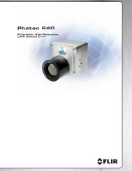
Product Description<br />
This product forms the interface between the <strong>Alpha</strong> camera and a digital acquisition system.<br />
Indigo’s Talon digital acquisition system (using a Bit Flow digital frame grabber) is configured<br />
to accept the data from the ADI. The ADI transforms the bite- serial, digital data from the<br />
camera into word- wide, parallel data conforming to the RS-422 electrical standard. A detailed<br />
description of the data format and timing is given below. The ADI provides power to the camera<br />
through the <strong>Alpha</strong> interface cable (shown in Figure A1).<br />
Warning!!! DO NOT apply power to the camera’s power input jack when<br />
the camera is connected to the ADI as damage to the camera may result!<br />
The video output from the camera is buffered in the ADI. A choice of video termination<br />
impedance is provided. Use LoZ for loads with 75 ohm input impedance and HiZ for high input<br />
impedance loads.<br />
Physical Interface and Dimensions<br />
The camera control is accomplished via the RS-232 interface. The interface software is provided<br />
with the <strong>Alpha</strong> camera and the physical interface is a standard 9-pin, sub-miniature D style<br />
connector (wired straight through). Overall chassis dimensions of the ADI are 8”W X 2.5”H X<br />
7”D, not including connectors. The standard length of the Interface Cable between the <strong>Alpha</strong><br />
and the ADI is 10 feet.<br />
Connecting the ADI<br />
Figure A1 shows the typical configuration of the ADI. Figures A2 and A3 show the front and<br />
rear panels, respectively.<br />
Note: Use only the supplied power supply for ADI power. Do not make any connections<br />
to the <strong>Alpha</strong> camera power or video jacks when using the ADI.<br />
28
<strong>Alpha</strong> User’s Guide 412-0003-10 Version 1.40<br />
<strong>Alpha</strong> Interface<br />
Cable (10 ft.)<br />
<strong>Alpha</strong> <strong>Camera</strong><br />
(not supplied)<br />
<strong>Alpha</strong><br />
<strong>Camera</strong><br />
Input<br />
Video Out<br />
Termination Switch<br />
ADI<br />
Digital Data<br />
Power Input<br />
Power On/Off<br />
Switch<br />
RS-232<br />
Video patch cable<br />
(not supplied)<br />
Digital Data Interface Cable (not supplied)<br />
RS-232 Interface Cable<br />
(not supplied)<br />
Figure A1. ADI Connections<br />
29<br />
Talon acquisition system<br />
or equivalent (not<br />
supplied)<br />
Wall mount power<br />
supply<br />
Video<br />
Monitor<br />
(not supplied)
<strong>Alpha</strong> User’s Guide 412-0003-10 Version 1.40<br />
Figure A2. ADI Front Panel<br />
Figure A3. ADI Rear Panel<br />
Digital Data<br />
The <strong>Alpha</strong> camera, when connected to the <strong>Alpha</strong> Digital Interface (ADI) accessory, will output<br />
real-time, 12-bit digital data to a digital frame grabber. The digital data bus output and timing<br />
are enabled at camera start-up. The digital data stream includes camera telemetry, group<br />
reference and pixel data. The pixel data may be represented as either pre-NUC (on command –<br />
neither NUC processing nor pixel replacement applied to the data) or post-NUC (default – NUC<br />
processing and pixel replacement applied to data). The digital data output from the ADI consists<br />
of 12-bit wide words generated at the DATA CLOCK rate. Each data word should be latched<br />
using the rising edge of the DATA CLOCK. The DATAFRAME pulse is one DATACLOCK<br />
period wide and represents the beginning of the image frame. The DATAVALID signal is<br />
asserted during valid group data. The first 20 groups (0 to 19) represent the camera telemetry<br />
data. The remaining groups represent the FPA pixel and group reference data. Figure A5 depicts<br />
the data output format and timing. The digital data and synchronization signals are transmitted in<br />
a differential format complying with RS-422 standards. For each output there are two<br />
complementary signals, a (+) indicating positive polarity and (-) indicating negative (inverted)<br />
polarity. A RS-422 compatible receiver with a 100 ohm termination (between the (+) and (-)<br />
signals) is recommended.<br />
30
<strong>Alpha</strong> User’s Guide 412-0003-10 Version 1.40<br />
Telemetry Data<br />
The ADI outputs telemetry information each frame period. The telemetry information is used to<br />
support factory calibration processes. The telemetry information consists of various camera<br />
operational parameters and occupies the first 20 groups (output words 0 to 159) in the digital data<br />
stream and replaces the pixel data from the first physical row of the array. A detailed description<br />
of the telemetry data format is found in Table A1.<br />
Note: The reference data has no relationship to the telemetry data.<br />
Pixel Data<br />
The ADI also outputs FPA pixel value and group reference data. The data is output in groups that<br />
include a reference and 8 pixels. In pre-NUC output mode, the group reference data should be<br />
subtracted from the 8 pixels that follow to improve the common-mode noise performance. In<br />
post-NUC mode, the reference subtraction is accomplished in the camera, therefore, the reference<br />
data should be ignored. The first group of pixel data is found ingroup number 20 (output word<br />
number 160). The first group of pixel data represents the first 8 pixels from the second row of<br />
the physical array (pixel coordinates row 1, columns 0 through 7). The data for pixels in the first<br />
physical row (row 0) is not available. Subsequent groups of data are in a raster type pattern (i.e.<br />
group # 21 contains pixels from row 1, columns 8 through 15; group # 22 contains pixels from<br />
row 1, columns 16 through 23). The total number of rows in the output is a function of the video<br />
format. For RS-170 video format, the number of rows is 119 while the number of rows for CCIR<br />
video format is 127.<br />
Serial Communications<br />
Serial communication to the camera is accomplished using a RS-232 command protocol. Please<br />
refer to Section 8.10 in this manual for more information.<br />
31
<strong>Alpha</strong> User’s Guide 412-0003-10 Version 1.40<br />
Parameter Word Group<br />
Bit Location<br />
Location Location 0 1 2 3 4 5 6 7 8 9 10 11<br />
FPA temperature 0 0 1 2 3 4 5 6 7 8 9 10 11<br />
1 12 13 L L L L L L L L L L<br />
Chassis 2 0 1 2 3 4 5 6 7 8 9 10 11<br />
Temperature 3 12 13 L L L L L L L L L L<br />
Chassis temp low<br />
threshold<br />
4<br />
5<br />
0<br />
0 1 2 3<br />
12 13 L L<br />
4<br />
L<br />
5<br />
L<br />
6<br />
L<br />
7<br />
L<br />
8 9 10 11<br />
L L L L<br />
Chassis temp 6 0 1 2 3 4 5 6 7 8 9 10 11<br />
high threshold 7<br />
12 13 L L L L L L L L L L<br />
Table switch data 8 0 1 2 3 4 5 6 7 8 9 10 11<br />
threshold 9 L L L L L L L L L L L L<br />
Population below 10 0 1 2 3 4 5 6 7 8 9 10 11<br />
data threshold 11<br />
1<br />
12 13 1<br />
4<br />
1<br />
5<br />
L L L L L L L L<br />
Population above 12 0 1 2 3 4 5 6 7 8 9 10 11<br />
data threshold 13 12 13 1 1 L L L L L L L L<br />
4 5<br />
Active calibration 14 0 1 2 3 4 5 6 7 L L L L<br />
table 15<br />
L L L L L L L L L L L L<br />
Reserved 16 - 159 2 - 19 H H H H H H H H H H H H<br />
Table A1. Telemetry data description<br />
19<br />
1<br />
20 37<br />
Mating connnector: AMP 747916-2<br />
Figure A4. Digital Output Connector, 37 pin D-sub, female (face view)<br />
32
<strong>Alpha</strong> User’s Guide 412-0003-10 Version 1.40<br />
Signal Name Pin<br />
Number<br />
Signal Name<br />
Ground 1 20 No Connect<br />
No Connect 2 21 Data 0 (+)<br />
Data 0 (-) 3 22 Data 1 (+)<br />
Data 1 (-) 4 23 Data 2 (+)<br />
Data 2 (-) 5 24 Data 3 (+)<br />
Data 3 (-) 6 25 Data 4 (+)<br />
Data 4 (-) 7 26 Data 5 (+)<br />
Data 5 (-) 8 27 Data 6 (+)<br />
Data 6 (-) 9 28 Data 7 (+)<br />
Data 7 (-) 10 29 Data 8 (+)<br />
Data 8 (-) 11 30 Data 9 (+)<br />
Data 9 (-) 12 31 Data 10 (+)<br />
Data 10 (-) 13 32 Data 11 (+)<br />
Data 11 (-) 14 33 Ground<br />
No Connect 15 34 Ground<br />
No Connect 16 35 Frame (+)<br />
Frame (-) 17 36 Data Valid (+)<br />
Data Valid (-) 18 37 Data Clock (+)<br />
Data Clock (-) 19<br />
Table A2. ADI Digital Output pin assignments<br />
33
DATAFRAME<br />
DATAVALID<br />
DATA<br />
DATAFRAME<br />
DATAVALID<br />
DATA<br />
DATACLOCK<br />
DATAVALID<br />
DATA<br />
<strong>Alpha</strong> User’s Guide 412-0003-10 Version 1.40<br />
Data<br />
0<br />
Latch DATAFRAME with<br />
falling edge of DATACLOCK<br />
Latch DATA with rising edge<br />
of DATACLOCK<br />
Data<br />
1<br />
Group 0 Group 1<br />
Group 2 Group 3 Group 4 Group 5<br />
Data<br />
2<br />
Ref 0 Word 0 Word 1 Word 2 Word 3 Word 4 Word 5 Word 6 Word 7<br />
Data<br />
3<br />
Data<br />
4<br />
225 DATACLOCK periods<br />
between DATAFRAME and<br />
reference data of first group<br />
Digital Data Word<br />
Data<br />
5<br />
Group<br />
Reference 0 Word 0<br />
Data<br />
6<br />
34<br />
34 DATACLOCK<br />
periods between groups<br />
Data<br />
7<br />
Data<br />
8<br />
Data<br />
9<br />
Data<br />
10<br />
Data<br />
11<br />
Figure A5. Digital Data Output Format & Timing (RS-170A video configuration)<br />
Word 1<br />
3.07 MHz<br />
Word 2 Word 3 Word 4
<strong>Alpha</strong> User’s Guide 412-0003-10 Version 1.40<br />
APPENDIX B INTELLIGENT ACCESSORY SHOE (HOT SHOE)<br />
Figure B1. <strong>Alpha</strong> Integrated with Sony Camcorder<br />
ThermoCordeR is an enhancement that transforms Indigo's <strong>Alpha</strong> infrared camera into a<br />
complete, handheld thermal imaging and recording system as shown in Figure B1.<br />
ThermoCordeR integrates <strong>Alpha</strong> with a Sony camcorder via the Intelligent Accessory Shoe (Hot<br />
Shoe) interface. This interface enables <strong>Alpha</strong>'s video signal to be input into the Sony camcorder<br />
for viewing on the LCD display or viewfinder (Figure B2). It also allows the camcorder battery<br />
to power the <strong>Alpha</strong>.<br />
Figure B2. <strong>Alpha</strong> Image Displayed on LCD<br />
Installation<br />
Mount the Hot Shoe to the bottom of the <strong>Alpha</strong> using the three supplied 4-40 x 2.00 Black Oxide<br />
socket head cap screws. Make sure the <strong>Alpha</strong>’s AUX I/O connector fully mates with the Hot<br />
Shoe. To connect the Hot Shoe to the camcorder, first verify the white arrow on the bottom of<br />
the Hot Shoe foot is pointing toward the rear of the assembly. If it is not, simply rotate the entire<br />
foot so that it is positioned properly. Next, slide the Hot Shoe foot into the camcorder accessory<br />
mount and place the locking ring in the LOCK position. The video signal from the <strong>Alpha</strong> is<br />
35
<strong>Alpha</strong> User’s Guide 412-0003-10 Version 1.40<br />
transferred to the camcorder by plugging the Hot Shoe video cable into the auxiliary<br />
Audio/Video (yellow) input located on the side of the camcorder.<br />
Warning!!! DO NOT apply power to the camera’s power input jack when<br />
the camera is connected to the Hot Shoe, as damage to the camera may<br />
result!<br />
Operation<br />
To turn on ThermoCordeR, switch the camcorder power selector switch to VCR. All standard<br />
features and furnished accessories of the Sony camcorder are available with ThermoCordeR.<br />
Recording of the video output from the camera is available on both mini-DV (digital video) tape<br />
and Memory Stick (digital still image) formats. The Hot Shoe adapter is designed to be<br />
compatible with any Sony camcorder featuring the Sony Intelligent Shoe. The baseline Sony<br />
camcorder model offered by Indigo is the DCR-TRV10. ThermoCordeR requires an <strong>Alpha</strong><br />
camera and Indigo's Hot Shoe adapter.<br />
Foot<br />
Figure B3. Hot Shoe Interface<br />
36<br />
Aux/IO<br />
Connector<br />
Video Cable