Regelventile Servo solenoid valves Servo ... - Airline Hydraulics
Regelventile Servo solenoid valves Servo ... - Airline Hydraulics
Regelventile Servo solenoid valves Servo ... - Airline Hydraulics

You also want an ePaper? Increase the reach of your titles
YUMPU automatically turns print PDFs into web optimized ePapers that Google loves.
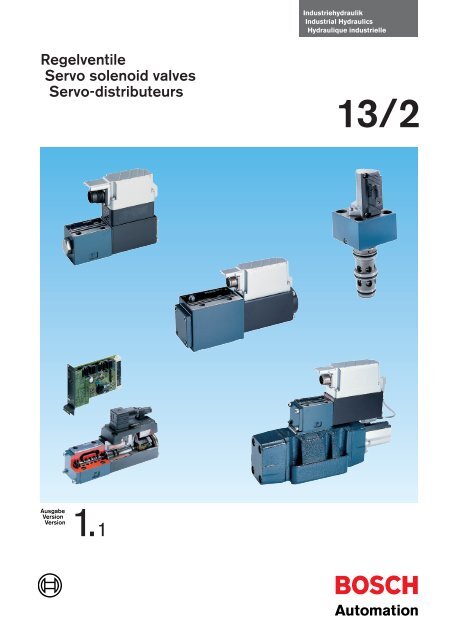
<strong>Regelventile</strong><br />
<strong>Servo</strong> <strong>solenoid</strong> <strong>valves</strong><br />
<strong>Servo</strong>-distributeurs<br />
Ausgabe<br />
Version<br />
Version 1.<br />
1<br />
Industriehydraulik<br />
Industrial <strong>Hydraulics</strong><br />
Hydraulique industrielle<br />
13/2
2 Industrial <strong>Hydraulics</strong><br />
A 1<br />
B<br />
1<br />
3<br />
2<br />
3<br />
5<br />
D<br />
2<br />
4<br />
C<br />
1<br />
2<br />
2<br />
1
y<br />
Bild A<br />
Regelventil, vorgesteuert<br />
1 Vorsteuerstufe<br />
Regelventil NG 6, Gehäuse<br />
mit Schieberhülse aus Stahl<br />
2 Regelmagnet mit<br />
integriertem Wegaufnehmer<br />
3 Hauptstufe<br />
Gehäuse aus Sphäroguß<br />
für präzise, verschleißfeste<br />
Steuerkanten<br />
4 Wegaufnehmer für<br />
Lageregelung der Hauptstufe<br />
5 Elektronik-Verstärker<br />
mit Lageregelung der<br />
Haupt- und Vorsteuerstufe<br />
Bild B<br />
HRV-Regelventil NG 6<br />
HRV: High Response Valve<br />
1 Hydraulikstufe mit Schieberhülse<br />
aus Stahl<br />
2 Regelmagnet mit integriertem<br />
Wegaufnehmer<br />
3 Elektronik-Verstärker<br />
mit Lageregelung<br />
Bild C<br />
Regelventil für Blockeinbau<br />
Vorsteuerung über Regelventil NG 6<br />
1 Hauptstufe mit Anschlüssen<br />
P-A/A-T<br />
2 Wegaufnehmer für Lageregelung<br />
im Verbund mit Regelventil NG 6<br />
Bild D<br />
Regelventil NG 6<br />
1 Hydraulikstufe mit Schieberhülse<br />
aus Stahl<br />
2 Regelmagnet mit integriertem<br />
Wegaufnehmer<br />
y<br />
Hinweis<br />
Weitere Kataloge und Informationen<br />
über Proportional- und <strong>Regelventile</strong>:<br />
K<br />
yy<br />
Picture A<br />
<strong>Servo</strong> <strong>solenoid</strong> valve,<br />
pilot operated<br />
1 Pilot stage<br />
<strong>Servo</strong> <strong>solenoid</strong> valve NG 6,<br />
housing with spool in steel<br />
sleeve<br />
2 <strong>Servo</strong> <strong>solenoid</strong> with integrated<br />
position transducer<br />
3 Main stage<br />
Housing made of graphite cast<br />
iron for accurate, wearresistant<br />
metering notches<br />
4 Position transducer for<br />
position control of main stage<br />
5 Electronic amplifier with position<br />
control of main and pilot stages<br />
Picture B<br />
HRV-<strong>Servo</strong> <strong>solenoid</strong> valve NG 6<br />
HRV: High Response Valve<br />
1 Hydraulic stage with spool in<br />
steel sleeve<br />
2 <strong>Servo</strong> <strong>solenoid</strong> with integrated<br />
position transducer<br />
3 Electronic amplifier with<br />
position control<br />
Picture C<br />
Cartridge-type servo <strong>solenoid</strong><br />
valve<br />
Pilot actuation via servo <strong>solenoid</strong><br />
valve NG 6<br />
1 Main stage with connections<br />
P-A/A-T<br />
2 Position transducer for position<br />
control in conjunction with servo<br />
<strong>solenoid</strong> valve NG 6<br />
Picture D<br />
<strong>Servo</strong> <strong>solenoid</strong> valve NG 6<br />
1 Hydraulic stage with spool in<br />
steel sleeve<br />
2 <strong>Servo</strong> <strong>solenoid</strong> with integrated<br />
position transducer<br />
yy<br />
Note<br />
Further catalogues and information on<br />
proportional <strong>valves</strong> and servo <strong>solenoid</strong><br />
<strong>valves</strong>:<br />
yyy<br />
Photo A<br />
<strong>Servo</strong>-distributeur, piloté<br />
1 Etage pilote<br />
<strong>Servo</strong>-distributeur NG 6,<br />
corps avec fourreau en acier<br />
2 Electro-aimant de regulation à<br />
capteur de position intégré<br />
3 Etage principal<br />
Corps en fonte à graphite<br />
sphéroïdal garantissant précision<br />
et résistance à l’usure<br />
4 Capteur de position pour asservissement<br />
en position de l’étage<br />
principal<br />
5 Amplificateur électronique<br />
avec régulation de position<br />
des étages principal et pilote<br />
Photo B<br />
HRV-<strong>Servo</strong>-distributeur NG 6<br />
HRV: High Response Valve<br />
1 Etage hydraulique avec fourreau<br />
en acier<br />
2 Electro-aimant de regulation à<br />
capteur de position intégré<br />
3 Amplificateur électronique<br />
avec régulation de position<br />
Photo C<br />
<strong>Servo</strong>-distributeur<br />
en cartouche<br />
Pilotage par servo-distributeur NG 6<br />
1 Etage principal avec raccords<br />
P-A/A-T<br />
2 Capteur de course pour asservissement<br />
en position en liaison<br />
avec servo-distributeur NG 6<br />
Photo D<br />
Industrial <strong>Hydraulics</strong> 3<br />
<strong>Servo</strong>-distributeur NG 6<br />
1 Etage hydraulique avec fourreau<br />
en acier<br />
2 Electro-aimant de regulation à<br />
capteur de position intégré<br />
yyy<br />
Remarque<br />
Autres catalogues et informations<br />
sur les <strong>valves</strong> proportionnelles et les<br />
servo-distributeurs:<br />
Proportionalventile NG 6, NG 10 AKY 013/1<br />
Proportional control <strong>valves</strong> NG 6, NG 10<br />
Valves proportionnelles NG 6, NG 10<br />
Proportionalventile, vorgesteuert, NG 10 bis NG 50 AKY 013/3<br />
Proportional <strong>valves</strong>, pilot operated, NG 10 to NG 50<br />
Valves proportionnelles, pilotées, NG 10 à NG 50<br />
Sensoren und Elektronik AKY 013/4<br />
Sensors and Electronics<br />
Capteurs et Electroniques<br />
Theorie und Praxis USY 013/1<br />
Theory and applications<br />
Théorie et pratique
4 Industrial <strong>Hydraulics</strong><br />
y<br />
Hinweise<br />
Allgemeines<br />
<strong>Regelventile</strong> von Bosch sind elektrohydraulische<br />
Stetigventile, die gerätetechnisch<br />
von den Proportionalventilen<br />
abgeleitet sind. Bezüglich ihrer statischen<br />
und dynamischen Kenngrößen<br />
stehen sie den <strong>Servo</strong>ventilen kaum<br />
nach, und sind somit als Stellglied in<br />
geschlossenen Regelkreisen zu verwenden.<br />
Nullüberdeckung<br />
Eine wichtige Voraussetzung für die<br />
Verwendung eines Stetigventils im<br />
geschlossenen Regelkreis ist die Nullüberdeckung<br />
im Bereich der Mittelstellung.<br />
Die Qualität der Nullüberdeckung<br />
kommt in den Diagrammen<br />
„Druckverstärkung“ zum Ausdruck.<br />
Nullüberdeckung setzt hohe Fertigungspräzision<br />
und Verwendung verschleißfester<br />
Materialien voraus.<br />
Dynamik<br />
Hohe Dynamik, also die Fähigkeit<br />
eines Ventils auf schnelle Signaländerungen<br />
ohne Verzögerung zu reagieren,<br />
wird erreicht durch:<br />
– Stetigmagnete mit erhöhter<br />
Stellkraft<br />
– verringerte Reibung der mechanisch<br />
bewegten Teile<br />
– weiterentwickelte Elektronikverstärker<br />
mit Schnellerregung und<br />
Schnellöschung.<br />
Dynamische Kenngrößen werden<br />
durch die Stellzeit und den Frequenzgang<br />
(Bode-Diagramm) zum Ausdruck<br />
gebracht.<br />
Hysterese, Wiederholgenauigkeit<br />
Die Schieber sämtlicher <strong>Regelventile</strong><br />
sind mit einer Lageregelung ausgestattet.<br />
Bei vorgesteuerten Ventilen<br />
sowohl die Schieber der Hauptstufe<br />
als auch der Vorsteuerstufe.<br />
Auf diese Weise werden optimale<br />
Werte bezüglich Hysterese, Wiederholgenauigkeit<br />
usw. erzielt.<br />
yy<br />
Notes<br />
General<br />
Bosch servo <strong>solenoid</strong> <strong>valves</strong> are<br />
electrohydraulic continuous-action<br />
<strong>valves</strong> developed from proportional<br />
control <strong>valves</strong>. They are in no way<br />
inferior to servo <strong>valves</strong> in terms of<br />
static and dynamic performance and<br />
so can be used as the final control<br />
element in closed control circuits.<br />
Zero overlap<br />
An important requirement for the use<br />
of a continuous-action valve in closed<br />
control circuits is zero overlap in the<br />
mid-position area. The precision of the<br />
zero overlap is expressed by a graph<br />
“Pressure gain”. Zero overlap requires<br />
high manufacturing precision and the<br />
use of hard-wearing materials.<br />
Dynamic Performance<br />
High dynamic performance is the<br />
ability of a valve to respond instantly<br />
to rapid changes in signal and is<br />
achieved by:<br />
– Continuous-action <strong>solenoid</strong>s with a<br />
high actuating force<br />
– Minimum friction in the mechanical<br />
moving parts<br />
– Sophisticated electronic amplifiers<br />
with rapid operating characteristics.<br />
The dynamic performance is expressed<br />
in terms of the actuating time and<br />
frequency response (Bode diagram).<br />
Hysteresis, repeatability<br />
The spools of all the servo <strong>solenoid</strong><br />
<strong>valves</strong> are equipped with position<br />
control; in pilot-operated <strong>valves</strong>, this<br />
applies to the spools of the main<br />
stage and the pilot stage. Optimum<br />
<strong>valves</strong> with regard to hysteresis,<br />
repeatability etc. are achieved in this<br />
way.<br />
yyy<br />
Remarques<br />
Généralités<br />
Les servo-distributeurs de Bosch<br />
entrent dans la catégorie des électro<strong>valves</strong><br />
à effet analogique. La technologie<br />
de cette gamme d’appareils découle<br />
de celle des <strong>valves</strong> à effet proportionnel.<br />
En considérant leurs<br />
performances statiques et dynamiques,<br />
elles avoisinent celles des<br />
servo-<strong>valves</strong>. Ils peuvent, de ce fait,<br />
être utilisés comme éléments de<br />
commande d’un circuit en boucle<br />
fermée.<br />
Recouvrement zéro<br />
Une condition fondamentale, pour<br />
qu’un distributeur à effet continu<br />
tienne ses performances dans un<br />
circuit en boucle fermée, réside<br />
dans la réalisation d’un recouvrement<br />
zéro lorsque le tiroir est en position<br />
médiane. La qualité de ce recouvrement<br />
s’exprime par un diagramme<br />
«amplification de la pression». Un<br />
bon recouvrement zéro impose une<br />
maîtrise de la précision de fabrication<br />
et l’utilisation de matériaux résistant<br />
à l’usure.<br />
Dynamique<br />
Une haute dynamique, c’est-à-dire<br />
l’aptitude de la valve à suivre sans<br />
déphasage les variations rapides du<br />
signal d’entrée, est obtenue par les<br />
aménagements suivants:<br />
– Electro-aimants dotés d’une grande<br />
force sur toute leur course<br />
– Faibles frottements des pièces<br />
mécaniques en mouvement<br />
– Amplificateurs électroniques<br />
perfectionnés équipés d’étages<br />
à excitation et désexcitation ultrarapides.<br />
Les performances dynamiques<br />
s’expriment par de faibles temps de<br />
réponse et une grande réponse en<br />
fréquence (diagramme de Bode).<br />
Hystérésis, répétabilité<br />
Les tiroirs de tous les servo-distributeurs<br />
sont asservis en position. Sur<br />
les <strong>valves</strong> pilotées, cette disposition<br />
concerne les tiroirs de l’étage principal<br />
et de l’étage pilote. On obtient de<br />
cette manière des valeurs optimales<br />
d’hystérésis, de répétabilité, etc.
Inhalt<br />
Contents<br />
Sommaire<br />
Industrial <strong>Hydraulics</strong> 5<br />
Benennung Seite Kapitel<br />
Description Page Section<br />
Désignation Page Chapitre<br />
NG 6<br />
<strong>Regelventile</strong> mit OBE<br />
<strong>Servo</strong> <strong>solenoid</strong> <strong>valves</strong> with OBE<br />
<strong>Servo</strong>-distributeurs avec OBE<br />
11<br />
1<br />
NG 6 HRV: High Response Valves 18<br />
HRV-<strong>Regelventile</strong> mit OBE<br />
HRV-<strong>Servo</strong> <strong>solenoid</strong> <strong>valves</strong> with OBE<br />
<strong>Servo</strong>-distributeurs HRV avec OBE<br />
NG 6 25<br />
<strong>Regelventile</strong> LVDT – DC<br />
<strong>Servo</strong> <strong>solenoid</strong> <strong>valves</strong> LVDT – DC<br />
<strong>Servo</strong>-distributeurs LVDT – DC<br />
NG 6 33<br />
<strong>Regelventile</strong> LVDT – AC<br />
<strong>Servo</strong> <strong>solenoid</strong> <strong>valves</strong> LVDT – AC<br />
<strong>Servo</strong>-distributeurs LVDT – AC<br />
2<br />
3<br />
4<br />
1<br />
2<br />
3<br />
4<br />
5<br />
6<br />
7<br />
8<br />
9<br />
10<br />
11<br />
12<br />
13<br />
14<br />
15<br />
16<br />
17
1<br />
2<br />
3<br />
4<br />
5<br />
6<br />
7<br />
8<br />
9<br />
10<br />
11<br />
12<br />
13<br />
14<br />
15<br />
16<br />
17<br />
6 Industrial <strong>Hydraulics</strong><br />
Benennung Seite Kapitel<br />
Description Page Section<br />
Désignation Page Chapitre<br />
NG 10 39<br />
<strong>Regelventile</strong> mit OBE<br />
<strong>Servo</strong> <strong>solenoid</strong> <strong>valves</strong> with OBE<br />
<strong>Servo</strong>-distributeurs avec OBE<br />
5<br />
NG 10 46<br />
<strong>Regelventile</strong> LVDT – DC<br />
<strong>Servo</strong> <strong>solenoid</strong> <strong>valves</strong> LVDT – DC<br />
<strong>Servo</strong>-distributeurs LVDT – DC<br />
NG 10 56<br />
p/Q-<strong>Regelventile</strong> mit OBE<br />
p/Q-<strong>Servo</strong> <strong>solenoid</strong> <strong>valves</strong> with OBE<br />
<strong>Servo</strong>-distributeurs p/Q avec OBE<br />
NG 10 63<br />
p/Q-<strong>Regelventile</strong> LVDT – DC<br />
p/Q-<strong>Servo</strong> <strong>solenoid</strong> <strong>valves</strong> LVDT – DC<br />
<strong>Servo</strong>-distributeurs p/Q LVDT – DC<br />
NG 10 ... 32, vorgesteuert / 74<br />
pilot operated / pilotées<br />
<strong>Regelventile</strong> mit OBE<br />
<strong>Servo</strong> <strong>solenoid</strong> <strong>valves</strong> with OBE<br />
<strong>Servo</strong>-distributeurs avec OBE<br />
6<br />
7<br />
8<br />
9
Industrial <strong>Hydraulics</strong> 7<br />
Benennung Seite Kapitel<br />
Description Page Section<br />
Désignation Page Chapitre<br />
NG 10 ... 25, vorgesteuert / 85<br />
pilot operated / pilotées<br />
HRV-<strong>Regelventile</strong> mit OBE<br />
HRV-<strong>Servo</strong> <strong>solenoid</strong> <strong>valves</strong> with OBE<br />
<strong>Servo</strong>-distributeurs HRV avec OBE<br />
10<br />
NG 10 ... 32, vorgesteuert / 96<br />
pilot operated / pilotées<br />
<strong>Regelventile</strong> LVDT – DC<br />
<strong>Servo</strong> <strong>solenoid</strong> <strong>valves</strong> LVDT – DC<br />
<strong>Servo</strong>-distributeurs LVDT – DC<br />
NG 25 ... 32, Blockeinbau / 109<br />
Cartridge-type / En cartouche<br />
3-Wege-<strong>Regelventile</strong><br />
3-way servo <strong>solenoid</strong> <strong>valves</strong><br />
<strong>Servo</strong>-distributeurs à 3 voies<br />
NG 6 ... 25 122<br />
Anschlußplatten, Lochbilder<br />
Subplates, Mounting hole<br />
configurations<br />
Embases, Plan de pose<br />
NG 6 ... 32 129<br />
Eingebaute Elektronik – OBE<br />
Varianten<br />
On-board electronics – OBE<br />
Variations<br />
Amplificateur intégré – OBE<br />
Variantes<br />
11<br />
12<br />
13<br />
14<br />
1<br />
2<br />
3<br />
4<br />
5<br />
6<br />
7<br />
8<br />
9<br />
10<br />
11<br />
12<br />
13<br />
14<br />
15<br />
16<br />
17
1<br />
2<br />
3<br />
4<br />
5<br />
6<br />
7<br />
8<br />
9<br />
10<br />
11<br />
12<br />
13<br />
14<br />
15<br />
16<br />
17<br />
8 Industrial <strong>Hydraulics</strong><br />
Benennung Seite Kapitel<br />
Description Page Section<br />
Désignation Page Chapitre<br />
Stecker für Ventile ohne OBE<br />
Plugs for <strong>valves</strong> without OBE<br />
Connecteurs pour <strong>valves</strong> sans OBE<br />
148<br />
Stecker für Ventile mit OBE 149<br />
Plugs for <strong>valves</strong> with OBE<br />
Connecteurs pour <strong>valves</strong> avec OBE<br />
Verstärker – Leiterkarten 155<br />
Amplifiers – Printed circuit boards<br />
Amplificateurs – Cartes imprimées<br />
Test- und Service-Geräte 184<br />
Testing and service equipment<br />
Appareil de test et de service<br />
15<br />
16<br />
17
Hinweise: Kapitel …<br />
Information: Sections …<br />
Remarques: chapitres … 6 1<br />
1<br />
6<br />
1 6<br />
y<br />
Einstufige Revelventile mit<br />
Schieberhülse<br />
Kapitel 1<br />
<strong>Regelventile</strong> NG 6 mit eingebauter<br />
Elektronik (OBE)<br />
– einseitig elektrisch betätigt, Failsafe-Position<br />
in abgeschaltetem<br />
Zustand<br />
– lineare Kennlinie, Nullschnitt<br />
– 7 P-Stecker<br />
– Ansteuersignal ± 10 V=<br />
– Differenzverstärkereingang.<br />
Mögliche Varianten auf Anfrage<br />
– geknickte Kennlinie<br />
– Fail-safe-Symbol abgeblockt<br />
– Signalnorm 4…20 mA.<br />
Kapitel 2<br />
High Response Valves NG 6<br />
HRV-<strong>Regelventile</strong> mit eingebauter<br />
Elektronik (OBE)<br />
– einseitig elektrisch betätigt, mittels<br />
Doppelhubmagnet, > Dynamik<br />
– lineare Kennlinie, Nullschnitt<br />
– 12 P-Stecker<br />
– Ansteuersignal ± 10 V=<br />
– Differenzverstärkereingang.<br />
Mögliche Varianten auf Anfrage<br />
– geknickte Kennlinie.<br />
Kapitel 3<br />
<strong>Regelventile</strong> NG 6 mit externem<br />
Ventilverstärker, LVDT – DC<br />
– einseitig elektrisch betätigt, Failsafe-Position<br />
in abgeschaltetem<br />
Zustand<br />
– lineare Kennlinie/geknickte<br />
Kennlinie Nullschnitt<br />
– Ventilverstärker mit/ohne Kennlinienanpassung<br />
(Knickkompensation)<br />
– Ansteuersignal ± 10 V=<br />
– Differenzverstärkereingang.<br />
Mögliche Varianten auf Anfrage<br />
– Fail-safe-Symbol abgeblockt.<br />
yy<br />
Single-stage servo <strong>solenoid</strong> <strong>valves</strong><br />
with spool sleeve<br />
Section 1<br />
<strong>Servo</strong> <strong>solenoid</strong> <strong>valves</strong> NG 6 with<br />
on-board electronics (OBE)<br />
– Electrically actuated on one side,<br />
fail-safe position when switched off<br />
– Linear curve, zero overlap<br />
– 7 P plug<br />
– Control signal ± 10 V=<br />
– Difference amplifier input.<br />
Possible variants on request<br />
– Non-linear curve<br />
– Fail-safe symbol blocked<br />
– Standard signal 4…20 mA.<br />
Section 2<br />
High Response Valves NG 6<br />
HRV servo <strong>solenoid</strong> <strong>valves</strong> with<br />
on-board electronics (OBE)<br />
– Electrically actuated on one side<br />
by means of double-stroke <strong>solenoid</strong>,<br />
> dynamics<br />
– Linear curve, zero overlap<br />
– 12 P plug<br />
– Control signal ± 10 V=<br />
– Difference amplifier input.<br />
Possible variants on request<br />
– Non-linear curve.<br />
Section 3<br />
<strong>Servo</strong> <strong>solenoid</strong> <strong>valves</strong> NG 6 with<br />
external valve amplifier, LVDT – DC<br />
– Electrically actuated on one side,<br />
fail-safe position when switched off<br />
– Linear curve/non-linear curve, zero<br />
overlap<br />
– Valve amplifier with/without curve<br />
adaptation (dual gain compensation)<br />
– Control signal ± 10 V=<br />
– Difference amplifier input.<br />
Possible variants on request<br />
– Fail-safe symbol blocked.<br />
Industrial <strong>Hydraulics</strong> 9<br />
yyy<br />
<strong>Servo</strong>-distributeurs à un étage avec<br />
fourreau<br />
Chapitre 1<br />
<strong>Servo</strong>-distributeurs NG 6 avec<br />
amplificateur intégré (OBE)<br />
– Commande électrique à un aimant,<br />
position «fail-safe» lorsque l’électroaimant<br />
n’est pas alimenté en tension<br />
– Courbe caractéristique linéaire,<br />
recouvrement zéro<br />
– Connecteur 7 P<br />
– Signal de pilotage ± 10 V=<br />
– Entrée amplificateur différence<br />
Variantes possibles sur demande<br />
– Courbe caractéristique brisée<br />
– Symbole «fail-safe» bloqué<br />
– Signal standard 4…20 mA.<br />
Chapitre 2<br />
High Response Valves NG 6<br />
<strong>Servo</strong>-distributeurs HRV avec<br />
amplificateur intégré (OBE)<br />
– Commande électrique à un aimant,<br />
avec aimant à double course,<br />
> dynamique<br />
– Courbe caractéristique linéaire,<br />
recouvrement zéro<br />
– Connecteur 12 P<br />
– Signal de pilotage ± 10 V=<br />
– Entrée amplificateur différence<br />
Variantes possibles sur demande<br />
– Courbe caractéristique brisée<br />
Chapitre 3<br />
<strong>Servo</strong>-distributeurs NG 6 avec amplificateur<br />
externe, LVDT – DC<br />
– Commande électrique à un aimant,<br />
position «fail-safe» lorsque l’électroaimant<br />
n’est pas alimenté en tension<br />
– Courbe caractéristique linéaire/<br />
courbe caractéristique brisée,<br />
recouvrement zéro<br />
– Amplificateur avec/sans adaptation<br />
courbe caractéristique (compensation<br />
du flambage)<br />
– Signal de pilotage ± 10 V=<br />
– Entrée amplificateur différence<br />
Variantes possibles sur demande<br />
– Symbole «fail-safe» bloqué
10 Industrial <strong>Hydraulics</strong><br />
y<br />
Kapitel 4<br />
<strong>Regelventile</strong> NG 6 mit externem<br />
Ventilverstärker, LVDT – AC<br />
– einseitig elektrisch betätigt, Failsafe-Position<br />
in abgeschaltetem<br />
Zustand<br />
– lineare Kennlinie, Nullschnitt<br />
– Low Cost-Ausführung<br />
– Leiterkarten-Varianten<br />
0…± 10 V= Signal<br />
6,5 … ± 3,5 V= Signal<br />
– Differenzverstärkereingang.<br />
Kapitel 5<br />
NG 10 <strong>Regelventile</strong> mit eingebauter<br />
Elektronik (OBE)<br />
– einseitig elektrisch betätigt, Failsafe-Position<br />
in abgeschaltetem<br />
Zustand<br />
– lineare Kennlinie, Nullschnitt<br />
– 7 P-Stecker<br />
– Ansteuersignal ± 10 V=<br />
– Differenzverstärkereingang.<br />
Mögliche Varianten auf Anfrage<br />
– geknickte Kennlinie<br />
– Fail-safe-Symbol abgeblockt<br />
– Signalnorm 4…20 mA.<br />
Kapitel 6<br />
<strong>Regelventile</strong> NG 10 mit externem<br />
Ventilverstärker, LVDT – DC<br />
– einseitig elektrisch betätigt, Failsafe-Position<br />
in abgeschaltetem<br />
Zustand<br />
– lineare Kennlinie/geknickte<br />
Kennlinie, Nullschnitt<br />
– Ventilverstärker mit/ohne Kennlinienanpassung<br />
(Knickkompensation)<br />
– Ansteuersignal ± 10 V=<br />
– Differenzverstärkereingang.<br />
Mögliche Varianten auf Anfrage<br />
– Fail-safe-Symbol abgeblockt.<br />
„Fail-safe“-Stellung<br />
Bei elektrisch abgeschaltetem Ventil<br />
(Magnet stromlos), nimmt der von der<br />
Feder betätigte Steuerschieber die<br />
sichere Stellung ein.<br />
Siehe Symbole 4/4 WV und 4/3 WV.<br />
Ausnahme sind HRV-Ventile.<br />
yy<br />
Section 4<br />
<strong>Servo</strong> <strong>solenoid</strong> <strong>valves</strong> NG 6 with<br />
external valve amplifier, LVDT – AC<br />
– Electrically actuated on one side,<br />
fail-safe position when switched off<br />
– Linear curve, zero overlap<br />
– Low-cost version<br />
– Printed circuit boards variants<br />
0…± 10 V= signal<br />
6.5 … ± 3.5 V= signal<br />
– Difference amplifier input.<br />
Section 5<br />
<strong>Servo</strong> <strong>solenoid</strong> <strong>valves</strong> NG 10 with<br />
on-board electronics (OBE)<br />
– Electrically actuated on one side,<br />
fail-safe position when switched off<br />
– Linear curve, zero overlap<br />
– 7 P plug<br />
– Control signal ± 10 V=<br />
– Difference amplifier input.<br />
Possible variants on request<br />
– Non-linear curve<br />
– Fail-safe symbol blocked<br />
– Standard signal 4…20 mA.<br />
Section 6<br />
<strong>Servo</strong> <strong>solenoid</strong> <strong>valves</strong> NG 10 with<br />
external valve amplifier, LVDT – DC<br />
– Electrically actuated on one side,<br />
fail-safe position when switched off<br />
– Linear curve/non-linear curve, zero<br />
overlap<br />
– Valve amplifier with / without curve<br />
adaptation (dual gain compensation)<br />
– Control signal ± 10 V=<br />
– Difference amplifier input.<br />
Possible variants on request<br />
– Fail-safe symbol blocked.<br />
Fail-safe position<br />
When the power supply to the valve is<br />
switched off (<strong>solenoid</strong> de-energized),<br />
the spring-actuated control spool<br />
moves to fail-safe position.<br />
See symbols 4/4 DCV and 4/3 DCV.<br />
HRV <strong>valves</strong> are an exception to this.<br />
yyy<br />
Chapitre 4<br />
<strong>Servo</strong>-distributeurs NG 6 avec<br />
amplificateur externe, LVDT – AC<br />
– Commande électrique à un aimant,<br />
position «fail-safe» lorsque l’électroaimant<br />
n’est pas alimenté en tension<br />
– Courbe caractéristique linéaire,<br />
recouvrement zéro<br />
– Version économique<br />
– Variants cartes imprimées<br />
0…± 10 V= signal<br />
6,5 … ± 3,5 V= signal<br />
– Entrée amplificateur différence<br />
Chapitre 5<br />
<strong>Servo</strong>-distributeurs NG 10 avec<br />
amplificateur intégré (OBE)<br />
– Commande électrique à un aimant,<br />
position «fail-safe» lorsque l’électroaimant<br />
n’est pas alimenté en tension<br />
– Courbe caractéristique linéaire,<br />
recouvrement zéro<br />
– Connecteur 7 P<br />
– Signal de pilotage ± 10 V=<br />
– Entrée amplificateur différence<br />
Variantes possibles sur demande<br />
– Courbe caractéristique brisée<br />
– Symbole «fail-safe» bloqué<br />
– Signal standard 4…20 mA.<br />
Chapitre 6<br />
<strong>Servo</strong>-distributeurs NG 10 avec<br />
amplificateur externe, LVDT – DC<br />
– Commande électrique à un aimant,<br />
position «fail-safe» lorsque l’électroaimant<br />
n’est pas alimenté en tension<br />
– Courbe caractéristique linéaire/<br />
courbe caractéristique brisée,<br />
recouvrement zéro<br />
– Amplificateur avec/sans adaptation<br />
courbe caractéristique (compensation<br />
du flambage)<br />
– Signal de pilotage ± 10 V=<br />
– Entrée amplificateur différence<br />
Variantes possibles sur demande<br />
– Symbole «fail-safe» bloqué<br />
Position «fail-safe»<br />
Lorsque le servo-distributeur est hors<br />
circuit (électro-aimant hors tension),<br />
le tiroir de commande actionné par le<br />
ressort retourne dans la position de<br />
sécurité.<br />
Voir symboles des distributeurs 4/4<br />
et 4/3.<br />
Exception: les <strong>valves</strong> HRV.
NG 6<br />
<strong>Regelventile</strong> mit OBE<br />
<strong>Servo</strong> <strong>solenoid</strong> <strong>valves</strong> with OBE<br />
<strong>Servo</strong>-distributeurs avec OBE<br />
Funktion<br />
Function<br />
Fonction<br />
EN 50 081-1<br />
EN 50 082-2<br />
Industrial <strong>Hydraulics</strong> 11<br />
Sinnbild<br />
Symbol<br />
∆p Qnom. pmax.<br />
Symbole V/VA max [bar] [l/min] [bar] [kg] «<br />
18 OBE 24 V= 35 4 P, A, B: 2,7 0 811 404 600<br />
40 VA max 12 315 0 811 404 601<br />
UD–E 0 … ±10 V 24 T: 250 0 811 404 602<br />
40 0 811 404 603<br />
01 OBE 4 0 811 404 610<br />
12 0 811 404 611<br />
24 0 811 404 612<br />
40 0 811 404 613<br />
18 OBE 24 V= 4 0 811 404 631<br />
40 VA max 12 0 811 404 632<br />
ID–E 4 … 20 mA 24 0 811 404 633<br />
40 0 811 404 634<br />
(4 x) f M 5 x 30 DIN 912–10.9 2 910 151 166<br />
* Stecker, 7polig KS 1 834 482 022<br />
Plug 7-pole KS 1 834 482 026<br />
Connecteur 7 pôles MS 1 834 482 023<br />
Seite MS 1 834 482 024<br />
Page 149 KS 90° 1 834 484 252<br />
Variante 4 … 20 mA-Signal / geknickte Kennlinie oder ohne Fail-safe, auf Anfrage<br />
Variant with 4 … 20 mA signal / non-linear curve or without fail-safe available on request<br />
Variante signal 4 … 20 mA / courbe caractéristique brisée ou sans «fail-safe», sur demande<br />
1
12 Industrial <strong>Hydraulics</strong><br />
1 y Kenngrößen<br />
Allgemein<br />
Bauart Schieberventil, direkt gesteuert, mit Stahlhülse<br />
Betätigung Proportionalmagnet mit Lageregelung – OBE<br />
Anschlußart Plattenanschluß, Lochbild NG 6 (ISO 4401)<br />
Einbaulage beliebig<br />
Umgebungstemperatur –20 … +50 °C<br />
Rüttelfestigkeit, Prüfbedingung<br />
Hydraulisch<br />
max. 25 g, Raumschüttelprüfung in allen Richtungen (24 h)<br />
Druckmittel Hydrauliköl nach DIN 51 524 … 535, andere Medien nach Rückfrage<br />
Viskosität, empfohlen 20 … 100 mm2 /s<br />
max. zulässig 10 … 800 mm2 /s<br />
Druckmitteltemperatur –20 … +70 °C<br />
Filterung Zulässige Verschmutzungsklasse Zu erreichen mit Filter<br />
des Druckmittels nach NAS 1638 x = 75<br />
Entsprechend Betriebssicherheit 7 X = 15<br />
und Lebensdauer 8 X = 10<br />
9 X = 15<br />
Durchflußrichtung siehe Sinnbild<br />
Nenndurchfluß [l/min]<br />
bei ∆p = 35 bar pro Kante*<br />
114 112 11241 140<br />
Max. Betriebsdruck Anschluß P, A, B: 315 bar<br />
Max. Druck Anschluß T: 250 bar<br />
Einsatzgrenzen bei<br />
∆p [bar]<br />
315 315 315 160<br />
315 315 250 100<br />
Lecköl [cm3 /min]<br />
bei 100 bar<br />
Statisch/Dynamisch<br />
180 300 500 900<br />
Hysterese 0,2%<br />
Exemplarstreuung Qmax.<br />
10%<br />
Stellzeit für Signalsprung 0 … 100% 10 ms<br />
Temperaturdrift Nullpunktverschiebung 1% bei ∆T= 40 °C<br />
Null-Abgleich ab Werk ±1%<br />
Konformität EN 50 081-1<br />
EN 50 082-2<br />
Elektrische Kenngrößen siehe Seite 130 (OBE)<br />
* Durchfluß bei anderem ∆p<br />
∆px<br />
Qx = QNenn. · 35
Industrial <strong>Hydraulics</strong> 13<br />
yy<br />
Characteristics<br />
General<br />
Construction Spool type valve, operated directly, with steel sleeve<br />
Actuation Proportional <strong>solenoid</strong> with position control – OBE<br />
Type of mounting Subplate, mounting hole configuration NG 6 (ISO 4401)<br />
Installation position Optional<br />
Ambient temperature –20 … +50 °C<br />
Vibration resistance, Test condition max. 25 g, shaken in 3 dimensions (24 h)<br />
Hydraulic<br />
Pressure fluid Hydraulic oil as per DIN 51 524 … 535, other fluids after prior consultation<br />
Viscosity, recommended 20 … 100 mm 2 /s<br />
max. permitted 10 … 800 mm 2 /s<br />
Pressure fluid temp. –20 … +70 °C<br />
Filtration Permissible contamination class of Achieved with filter<br />
pressure fluid as per NAS 1638 x = 75<br />
In line with opera- 7 X = 15<br />
tional reliability 8 X = 10<br />
and service life 9 X = 15<br />
Flow direction See symbol<br />
Nominal flow [l/min] 14 112 1241 40<br />
at ∆p = 35 bar per notch*<br />
Max. working pressure Port P, A, B: 315<br />
Max. pressure Port T: 250 bar<br />
Operating limits at 315 315 315 160<br />
∆p [bar]<br />
315 315 250 100<br />
Leakage [cm3 /min]<br />
at 100 bar<br />
Static/Dynamic<br />
180 300 500 900<br />
Hysteresis 0.2%<br />
Manufacturing tolerance for Qmax.<br />
10%<br />
Response time for signal 0 … 100% 10 ms<br />
Termal drift Zero point displacement 1%, at ∆T= 40 °C<br />
Zero adjustment Factory-set ±1%<br />
Conformity EN 50 081-1<br />
EN 50 082-2<br />
Electrical characteristics See page 130 (OBE)<br />
* Flow rate at a different of ∆p<br />
∆px<br />
Qx = QNom. · 35<br />
1
14 Industrial <strong>Hydraulics</strong><br />
1 yyy<br />
Caractéristiques<br />
Générales<br />
Construction Distributeur à tiroir, à commande directe avec fourreau en acier<br />
Commande Aimant à action proportionnelle avec régulation de position – OBE<br />
Raccordement Embase selon plan de pose NG 6 (ISO 4401)<br />
Position de montage indifférente<br />
Température ambiante –20 … +50 °C<br />
Vibrations, Condition du test<br />
Hydrauliques<br />
max. 25 g, 3 dimensions (24 h)<br />
Fluide Huile hydraulique selon norme DIN 51 524 … 535, autre fluide sur demande<br />
Viscosité conseillée 20 … 100 mm2 /s<br />
max. adm. 10 … 800 mm2 /s<br />
Température du fluide –20 … +70 °C<br />
Filtration Classe de pollution admissible Avec un filtre<br />
du fluide selon NAS 1638 x = 75<br />
Selon la sécurité de 7 X = 15<br />
fonctionnement et la 8 X = 10<br />
durée de vie 9 X = 15<br />
Sens d’écoulement voir symbole<br />
Débit nominal [l/min] pour<br />
∆p = 35 bar par arête*<br />
114 112 11241 140<br />
Pression de service max. Orifices P, A, B: 315 bar<br />
Pression max. Orifice T: 250 bar<br />
Limites d’utilisation<br />
à ∆p [bar]<br />
315 315 315 160<br />
315 315 250 100<br />
Fuites internes [cm3 /min]<br />
à 100 bar<br />
Statiques/Dynamiques<br />
180 300 500 900<br />
Hystérésis 0,2%<br />
Dispersion pour Qmax.<br />
10%<br />
Temps de réponse pour 10 ms<br />
une course de 0 … 100%<br />
Dérive en température Déplacement du point zéro 1% pour ∆T= 40 °C<br />
Tarage du zéro A l’usine ±1%<br />
Conformité EN 50 081-1<br />
EN 50 082-2<br />
Caractéristiques électriques voir page 130 (OBE)<br />
* Débit sous ∆p différent<br />
∆px<br />
Qx = QNom. · 35
Fail-safe-Position<br />
Fail-safe position<br />
Position «fail-safe»<br />
Industrial <strong>Hydraulics</strong> 15<br />
Fail-safe-Position<br />
Lecköl bei 100 bar P–A 50 cm 3 /min<br />
Leakage at P–B 70 cm 3 /min<br />
Fuites internes à<br />
Durchfluß bei ∆p = 35 bar A–T 10 … 20 l/min<br />
Flow at B–T 7 … 20 l/min<br />
Débit à<br />
Lecköl bei 100 bar P–A 50 cm 3 /min<br />
Leaklage at P–B 70 cm 3 /min<br />
Fuites internes à A–T 70 cm 3 /min<br />
B–T 50 cm 3 /min<br />
Fail-safe p = 0 bar → 7 m sec<br />
• p = 100 bar → 10 m sec<br />
Interne Freigabe aus<br />
Internal enable off<br />
Déblocage arrêt interne<br />
UB 18 V=<br />
(ID-E 2 mA)<br />
y<br />
Steckerbelegung 7 P<br />
Ventil … mit Lageregelung<br />
UE = 0 ... ±10 V<br />
Ri = 100 kΩ<br />
UD–E ±10 V<br />
y<br />
Steckerbelegung 7 P<br />
Ventil … mit Lageregelung<br />
I = 4 ... 20 mA, Bürde = 200 Ω<br />
ID–E 4 ... 20 mA<br />
yy<br />
Pin assignment 7 P<br />
Valve … with position control<br />
UE = 0 ... ±10 V<br />
Ri = 100 kΩ<br />
yy<br />
Pin assignment 7 P<br />
Valve … with position control<br />
I = 4 ... 20 mA, load = 200 Ω<br />
yyy<br />
Affectation du connecteur 7 P<br />
Valve … avec régulation de position<br />
UE = 0 ... ±10 V<br />
Ri = 100 kΩ<br />
yyy<br />
Affectation du connecteur 7 P<br />
Valve … avec régulation<br />
de position<br />
I = 4 ... 20 mA, charge = 200 Ω<br />
1
1<br />
16 Industrial <strong>Hydraulics</strong><br />
Volumenstrom – Signalfunktion<br />
Flow rate/signal function<br />
Débit en fonction du signal<br />
Druckverstärkung<br />
Pressure gain<br />
Amplification de pression<br />
Bode-Diagramm<br />
Bode diagram<br />
Diagramme de Bode<br />
• kalibriert<br />
calibrated<br />
tarage ±1%<br />
* Fail-safe: UB 18 V=<br />
(Version UD–E)<br />
* Fail-safe: UB 18 V= / ID-E 2 mA<br />
(Version ID–E 4 … 20 mA)
Abmessungen<br />
Dimensions<br />
Cotes d’encombrement<br />
y<br />
Abmessungen des Anschlußlochbildes<br />
NG 6 ISO 4401,<br />
siehe Seite 125.<br />
yy<br />
Dimensions of mounting hole<br />
configuration NG 6 ISO 4401<br />
see page 125.<br />
Industrial <strong>Hydraulics</strong> 17<br />
yyy<br />
Cotes du plan de pose NG 6<br />
ISO 4401, voir page 125.<br />
1
2<br />
18 Industrial <strong>Hydraulics</strong><br />
NG 6 HRV: High Response Valves<br />
HRV-<strong>Regelventile</strong> mit OBE<br />
HRV-<strong>Servo</strong> <strong>solenoid</strong> <strong>valves</strong> with OBE<br />
<strong>Servo</strong>-distributeurs HRV avec OBE<br />
Funktion<br />
Function<br />
Fonction<br />
EN 50 081-1<br />
EN 50 082-2<br />
Sinnbild ∆p Qnom. pmax.<br />
Symbol<br />
Symbole V/VA max [bar] [l/min] [bar] [kg] «<br />
OBE 24 V= 35 8 P, A, B: 2,5 0 811 404 723<br />
25 VA max 12 315 0 811 404 722<br />
UD–E 0 … ±10 V 24 T: 0 811 404 721<br />
40 100 0 811 404 720<br />
OBE 15 0 811 404 725<br />
25 0 811 404 726<br />
(4 x) f M 5 x 30 DIN 912–10.9 2 910 151 166<br />
* Stecker, 12polig KS 1 834 484 142<br />
Plug 12-pole<br />
Connecteur 12 pôles<br />
Seite<br />
Page 149<br />
Variante geknickte Kennlinie, auf Anfrage<br />
Variant with non-linear curve available on request<br />
Variante courbe caractéristique brisée, sur demande
Industrial <strong>Hydraulics</strong> 19<br />
y<br />
Kenngrößen<br />
Allgemein<br />
Bauart Schieberventil, direkt gesteuert, mit Stahlhülse<br />
Betätigung Proportional-Doppelhub-Magnet mit Lageregelung – OBE<br />
Anschlußart Plattenanschluß, Lochbild NG 6 (ISO 4401)<br />
Einbaulage beliebig<br />
Umgebungstemperatur –20 … +50 °C<br />
Rüttelfestigkeit, Prüfbedingung max. 25 g, Raumschüttelprüfung in allen Richtungen (24 h)<br />
Hydraulisch<br />
Druckmittel Hydrauliköl nach DIN 51 524 … 535, andere Medien nach Rückfrage<br />
Viskosität, empfohlen 20 … 100 mm 2 /s<br />
max. zulässig 10 … 800 mm 2 /s<br />
Druckmitteltemperatur –20 … +65 °C<br />
Filterung Zulässige Verschmutzungsklasse Zu erreichen mit Filter<br />
des Druckmittels nach NAS 1638 x = 75<br />
Entsprechend 7 X = 15<br />
Betriebssicherheit 8 X = 10<br />
und Lebensdauer 9 X = 15<br />
Durchflußrichtung siehe Sinnbild<br />
Nenndurchfluß [l/min] bei
2<br />
20 Industrial <strong>Hydraulics</strong><br />
yy<br />
Characteristics<br />
General<br />
Construction Spool type valve, operated directly, with steel sleeve<br />
Actuation Proportional double-stroke <strong>solenoid</strong> with position control – OBE<br />
Type of mounting Subplate, mounting hole configuration NG 6 (ISO 4401)<br />
Installation position Optional<br />
Ambient temperature –20 … +50 °C<br />
Vibration resistance, Test condition max. 25 g, shaken in 3 dimensions (24 h)<br />
Hydraulic<br />
Pressure fluid Hydraulic oil as per DIN 51 524 … 535, other fluids after prior consultation<br />
Viscosity, recommended 20 … 100 mm 2 /s<br />
max. permitted 10 … 800 mm 2 /s<br />
Pressure fluid temp. –20 … +65 °C<br />
Filtration Permissible contamination class Achieved with filter<br />
of pressure fluid as per NAS 1638 x = 75<br />
In line with opera- 7 X = 15<br />
tional reliability 8 X = 10<br />
and service life 9 X = 15<br />
Flow direction See symbol<br />
Nominal flow [l/min] at
Industrial <strong>Hydraulics</strong> 21<br />
yyy<br />
Caractéristiques<br />
Générales<br />
Construction Distributeur à tiroir, à commande directe avec fourreau en acier<br />
Commande Aimant à double course à action proportionnelle avec régulation de position – OBE<br />
Raccordement Embase selon plan de pose NG 6 (ISO 4401)<br />
Position de montage indifférente<br />
Température ambiante –20 … +50 °C<br />
Vibrations, Condition du test max. 25 g, 3 dimensions (24 h)<br />
Hydrauliques<br />
Fluide Huile hydraulique selon norme DIN 51 524 … 535, autre fluide sur demande<br />
Viscosité conseillée 20 … 100 mm 2 /s<br />
max. adm. 10 … 800 mm 2 /s<br />
Température du fluide –20 … +65 °C<br />
Filtration Classe de pollution admissible Avec un filtre<br />
du fluide selon NAS 1638 x = 75<br />
Selon la sécurité de 7 X = 15<br />
fonctionnement et la 8 X = 10<br />
durée de vie 9 X = 15<br />
Sens d’écoulement voir symbole<br />
Débit nominal [l/min] pour
2<br />
22 Industrial <strong>Hydraulics</strong><br />
y<br />
Steckerbelegung 12 P<br />
Ventil … mit Lageregelung<br />
UE = ±10 V, Ri = 100 kΩ<br />
yy<br />
Pin assignment 12 P<br />
Valve … with position control<br />
UE = ±10 V, Ri = 100 kΩ<br />
yyy<br />
Affectation du connecteur 12 P<br />
Valve … avec régulation de position<br />
UE = ±10 V, Ri = 100 kΩ
Bode-Diagramm<br />
Bode diagram<br />
Diagramme de bode<br />
Druckverstärkung<br />
Pressure gain<br />
Amplification de pression<br />
Volumenstrom – Signalfunktion<br />
Flow rate/signal function<br />
Débit en fonction du signal<br />
Linear Knick 60%<br />
QN 8 … 40 l/min<br />
QN 15 … 25 l/min<br />
Industrial <strong>Hydraulics</strong> 23<br />
• kalibriert<br />
calibrated<br />
tarage ±1%<br />
2
2<br />
24 Industrial <strong>Hydraulics</strong><br />
Abmessungen<br />
Dimensions<br />
Cotes d’encombrement<br />
y<br />
Abmessungen des Anschlußlochbildes<br />
NG 6 ISO 4401,<br />
siehe Seite 125.<br />
yy<br />
Dimensions of mounting hole<br />
configuration NG 6 ISO 4401<br />
see page 125.<br />
yyy<br />
Cotes du plan de pose NG 6<br />
ISO 4401, voir page 125.
NG 6<br />
<strong>Regelventile</strong> LVDT–DC<br />
<strong>Servo</strong> <strong>solenoid</strong> <strong>valves</strong> LVDT–DC<br />
<strong>Servo</strong>-distributeurs LVDT–DC<br />
Funktion<br />
Function<br />
Fonction<br />
Sinnbild Linear Knick 60% Knick 40%<br />
Symbol<br />
Symbole<br />
18<br />
01<br />
nur bei<br />
Knick (40%) + 2:1 (A:B) only for (QN 40 l)<br />
seulement pour<br />
Industrial <strong>Hydraulics</strong> 25<br />
3
3<br />
26 Industrial <strong>Hydraulics</strong><br />
NG 6<br />
Programm-Übersicht<br />
Product range<br />
Gamme des produits<br />
Sinnbild ∆p Qnom. pmax.<br />
Symbol<br />
Symbole V/VA max [bar] [l/min] [bar] [kg] «<br />
18 2,7/40 35 2 P, A, B: 1-K 2,3 0 811 404 041<br />
4 315 0 811 404 033<br />
12 T: 0 811 404 034<br />
24 250 0 811 404 035<br />
40 0 811 404 036<br />
01 4 0 811 404 160<br />
12 0 811 404 037<br />
24 0 811 404 038<br />
40 0 811 404 039<br />
18 60% 2,7/40 35 15 P, A, B: 2-K 2,3 0 811 404 047<br />
24 315 0 811 404 043<br />
T:<br />
250<br />
01 60% 15 0 811 404 048<br />
24 0 811 404 045<br />
18 40% 2,7/40 35 40 P, A, B: 3-K 2,3 0 811 404 044<br />
315<br />
T:<br />
250<br />
01 40% 40 0 811 404 046<br />
40 0 811 404 162<br />
A:B = 2:1<br />
(4 x) f M 5 x 30 DIN 912–10.9 2 910 150 166<br />
K Seite PL 6 1-K 0,2 0 811 405 060<br />
Page PL 6 – AGC2 (60%) 2-K 0,25 0 811 405 066<br />
155 PL 6 – AGC1 (40%) 3-K 0,25 0 811 405 065<br />
3 P (PG 11) Im Lieferumfang enthalten Seite<br />
4 P (PG 7) Included in scope of delivery Page 148<br />
3 P 4 P Compris dans la fourniture<br />
y<br />
Anwendung:<br />
– <strong>Regelventile</strong> mit geknickter<br />
Kennlinie im System, siehe<br />
AKY 013/4 und BEY 017/1.<br />
– Ventilverstärker mit Druckregler<br />
(pQ), siehe AKY 013/4,<br />
UBY 013/84 und UBY 013/124.<br />
yy<br />
Application:<br />
– <strong>Servo</strong> <strong>solenoid</strong> <strong>valves</strong> with nonlinear<br />
curve in the system, see<br />
AKY 013/4 and BEY 017/1.<br />
– Valve amplifiers with pressure compensator<br />
(pQ), see AKY 013/4,<br />
UBY 013/84 and UBY 013/124.<br />
yyy<br />
Application:<br />
– <strong>Servo</strong>-distributeurs à caractéristique<br />
brisée dans le système, voir<br />
AKY 013/4 et BEY 017/1.<br />
– Amplificateurs avec régulateur de<br />
pression (pQ), voir AKY 013/4,<br />
UBY 013/84 et UBY 013/124.
Industrial <strong>Hydraulics</strong> 27<br />
y<br />
Kenngrößen<br />
Allgemein<br />
Bauart Schieberventil, direkt gesteuert, mit Stahlhülse<br />
Betätigung Proportionalmagnet mit Lageregelung, Ventilverstärker extern<br />
Anschlußart Plattenanschluß, Lochbild NG 6 (ISO 4401)<br />
Einbaulage beliebig<br />
Umgebungstemperatur –20 … +50 °C<br />
Rüttelfestigkeit, Prüfbedingung max. 25 g, Raumschüttelprüfung in allen Richtungen (24 h)<br />
Hydraulisch<br />
Druckmittel Hydrauliköl nach DIN 51 524 … 535, andere Medien nach Rückfrage<br />
Viskosität, empfohlen 20 … 100 mm 2 /s<br />
max. zulässig 10 … 800 mm 2 /s<br />
Druckmitteltemperatur –20 … +80 °C<br />
Filterung Zulässige Verschmutzungsklasse Zu erreichen mit Filter<br />
des Druckmittels nach NAS 1638 x = 75<br />
Entsprechend 7 X = 15<br />
Betriebssicherheit 8 X = 10<br />
und Lebensdauer 9 X = 15<br />
Durchflußrichtung siehe Sinnbild<br />
Nenndurchfluß [l/min] bei 2 4 12 15 24 40<br />
∆p = 35 bar pro Kante*<br />
Max. Betriebsdruck Anschluß P, A, B: 315 bar<br />
Max. Druck Anschluß T: 250 bar<br />
Einsatzgrenzen ∆p [bar] < 315 < 315 < 315 < 315 < 315 < 160<br />
< 315 < 315 < 315 < 280 < 250 < 100<br />
Lecköl [cm 3 /min] < 150 < 180 < 300
3<br />
28 Industrial <strong>Hydraulics</strong><br />
yy<br />
Characteristics<br />
General<br />
Construction Spool type valve, operated directly, with steel sleeve<br />
Actuation Proportional <strong>solenoid</strong> with position control, amplifier external<br />
Type of mounting Subplate, mounting hole configuration NG 6 (ISO 4401)<br />
Installation position Optional<br />
Ambient temperature range –20 … +50 °C<br />
Vibration resistance, test condition max. 25 g, shaken in 3 dimensions (24 h)<br />
Hydraulic<br />
Pressure fluid Hydraulic oil as per DIN 51 524 … 535, other fluids after prior consultation<br />
Viscosity, recommended 20 … 100 mm 2 /s<br />
max. permitted 10 … 800 mm 2 /s<br />
Pressure fluid temperature –20 … +80 °C<br />
Filtration Permissible contamination class Achieved using filter<br />
of pressure fluid as per NAS 1638 x = 75<br />
In line with opera- 7 X = 15<br />
tional reliability 8 X = 10<br />
and service life 9 X = 15<br />
Flow direction See symbol<br />
Nominal flow [l/min] at 2 4 12 15 24 40<br />
∆p = 35 bar per notch*<br />
Max. working pressure Port P, A, B: 315 bar<br />
Max. pressure Port T: 250 bar<br />
Operating limits at ∆p [bar] < 315 < 315 < 315 < 315 < 315 < 160<br />
< 315 < 315 < 315 < 280 < 250 < 100<br />
Leakage [cm 3 /min] < 150 < 180 < 300
Industrial <strong>Hydraulics</strong> 29<br />
yyy<br />
Caractéristiques<br />
Générales<br />
Construction Distributeur à tiroir, à commande directe avec fourreau en acier<br />
Commande Aimant à action proportionnelle avec régulation de position, amplificateur externe<br />
Raccordement Embase selon plan de pose NG 6 (ISO 4401)<br />
Position de montage indifférente<br />
Température ambiante –20 … +50 °C<br />
Vibrations, condition du test max. 25 g, 3 dimensions (24 h)<br />
Hydrauliques<br />
Fluide Fluide hydraulique selon norme DIN 51 524 … 535, autre fluide sur demande<br />
Viscosité, conseillée 20 … 100 mm 2 /s<br />
max. admissible 10 … 800 mm 2 /s<br />
Température du fluide –20 … +80 °C<br />
Filtration Classe de pollution admissible Avec un filtre<br />
du fluide selon NAS 1638 x = 75<br />
Selon sécurité de 7 X = 15<br />
fonctionnement et 8 X = 10<br />
durée de vie 9 X = 15<br />
Sens d’écoulement voir symbole<br />
Débit nominal [l/min] pour 2 4 12 15 24 40<br />
∆p = 35 bar arête*<br />
Pression de service max. Orifices P, A, B: 315 bar<br />
Pression max. Orifice T: 250 bar<br />
Limites d’utilisation < 315 < 315 < 315 < 315 < 315 < 160<br />
à ∆p [bar]<br />
< 315 < 315 < 315 < 280 < 250 < 100<br />
Fuites internes [cm 3 /min] < 150 < 180 < 300
3<br />
30 Industrial <strong>Hydraulics</strong><br />
Volumenstrom – Signalfunktion<br />
Flow rate/signal function<br />
Débit en fonction du signal<br />
Q = f (UE)<br />
Linear **Knick 60%<br />
**Knick 60% **Knick 40%<br />
y<br />
** Fail-safe, wenn Freigabe gesperrt.<br />
** Q-Knick = 10% QN.<br />
Druckverstärkung<br />
Pressure gain<br />
Amplification de pression<br />
yy<br />
** Fail-safe, when enabling is not<br />
released.<br />
** Q-Knick = 10% QN.<br />
yyy<br />
** Fail-safe, en cas de blocage.<br />
** Q-Knick = 10% QN.
Bode-Diagramm<br />
Bode diagram<br />
Diagramme de Bode<br />
Fail-safe-Position<br />
Fail-safe position<br />
Position «fail-safe»<br />
Industrial <strong>Hydraulics</strong> 31<br />
Fail-safe-Position<br />
Lecköl bei 100 bar P–A 50 cm 3 /min<br />
Leakage at P–B 70 cm 3 /min<br />
Fuites internes à<br />
Durchfluß bei ∆p = 35 bar A–T 10 … 20 l/min<br />
Flow at B–T 7 … 20 l/min<br />
Débit à<br />
Lecköl bei 100 bar P–A 50 cm 3 /min<br />
Leaklage at P–B 70 cm 3/min<br />
Fuites internes à A–T 70 cm 3/min<br />
B–T 50 cm 3/min<br />
Fail-safe p = 0 bar → 7 m sec<br />
• p = 100 bar → 10 m sec<br />
Freigabe aus<br />
Enable off<br />
Déblocage arrêt<br />
3
3<br />
32 Industrial <strong>Hydraulics</strong><br />
Abmessungen<br />
Dimensions<br />
Cotes d’encombrement<br />
y<br />
Abmessungen des Anschlußlochbildes<br />
NG 6 ISO 4401,<br />
siehe Seite 125.<br />
yy<br />
Dimensions of mounting hole<br />
configuration NG 6 ISO 4401<br />
see page 125.<br />
yyy<br />
Cotes du plan de pose<br />
NG 6 ISO 4401, voir page 125.
NG 6<br />
<strong>Regelventile</strong> LVDT–AC<br />
<strong>Servo</strong> <strong>solenoid</strong> <strong>valves</strong> LVDT–AC<br />
<strong>Servo</strong>-distributeurs LVDT–AC<br />
Funktion<br />
Function<br />
Fonction<br />
y<br />
Diese <strong>Regelventile</strong> mit Nullüberdeckung<br />
entsprechen in ihrer<br />
Magnet- und Wegaufnehmertechnik<br />
den Proportionalventilen<br />
NG 6 (LVDT – AC).<br />
Sie stellen eine preiswerte Alternative<br />
zu Standard-<strong>Regelventile</strong>n bei<br />
eingeschränkten statischen und<br />
dynamischen Kenngrößen dar.<br />
yy<br />
These servo <strong>solenoid</strong> <strong>valves</strong> with<br />
zero overlap are fitted with a <strong>solenoid</strong><br />
and a position transducer, the<br />
technology of which corresponds<br />
to that of NG 6 (LVDT – AC) proportional<br />
control <strong>valves</strong>.<br />
They are an economical alternative<br />
to standard servo <strong>solenoid</strong> <strong>valves</strong><br />
with reduced static and dynamic<br />
characteristics.<br />
Industrial <strong>Hydraulics</strong> 33<br />
yyy<br />
Ces servo-distributeurs à recouvrement<br />
zéro utilisent un électro-aimant<br />
et un capteur de position dont la<br />
technique correspond à celle des<br />
<strong>valves</strong> à effet proportionnel NG 6<br />
(LVDT – AC).<br />
Ils constituent une alternative économique<br />
aux servo-distributeurs<br />
standard et présentent des caractéristiques<br />
statiques et dynamiques<br />
restreintes.<br />
Sinnbild ∆p Qnom. pmax.<br />
Symbol<br />
Symbole V/VA max [bar] [l/min] [bar] [kg] «<br />
18 2,7/35 35 4 P, A, B: 1-K 2,2 0 811 404 122<br />
12 250 2-K 0 811 404 111<br />
24 T: 250 0 811 404 106<br />
40 0 811 404 113<br />
01 12 0 811 404 112<br />
24 0 811 404 118<br />
(4 x) f M 5 x 30 DIN 912–10.9 2 910 151 166<br />
K Seite RV 45 1-K 0,2 0 811 405 148<br />
Page 155 RV 45±/–10 V 2-K 0,2 0 811 405 123<br />
3 P (PG 11) Im Lieferumfang enthalten Seite<br />
3 P (PG 7)* Included in scope of delivery Page 148<br />
Compris dans la fourniture<br />
3 P 3 P*<br />
4
4<br />
34 Industrial <strong>Hydraulics</strong><br />
y<br />
Kenngrößen<br />
Allgemein<br />
Bauart Schieberventil, direkt gesteuert, mit Stahlhülse<br />
Betätigung Proportionalmagnet mit Lageregelung, Ventilverstärker extern<br />
Anschlußart Plattenanschluß, Lochbild NG 6 (ISO 4401)<br />
Einbaulage beliebig<br />
Umgebungstemperatur –20 … +50 °C<br />
Rüttelfestigkeit, Prüfbedingung max. 25 g, Raumschüttelprüfung in allen Richtungen (24 h)<br />
Hydraulisch<br />
Druckmittel Hydrauliköl nach DIN 51 524 … 535, andere Medien nach Rückfrage<br />
Viskosität, empfohlen 20 … 100 mm 2 /s<br />
max. zulässig 10 … 800 mm 2 /s<br />
Druckmitteltemperatur –20 … +80 °C<br />
Filterung Zulässige Verschmutzungsklasse Zu erreichen mit Filter<br />
des Druckmittels nach NAS 1638 x = 75<br />
Entsprechend Betriebssicherheit 7 X = 15<br />
und Lebensdauer 8 X = 10<br />
9 X = 15<br />
Durchflußrichtung siehe Sinnbild<br />
Nenndurchfluß [l/min] 14 112 1241 40<br />
bei ∆p = 35 bar pro Kante*<br />
Max. Betriebsdruck Anschluß P, A, B: 250 bar<br />
Max. Druck Anschluß T: 250 bar<br />
Einsatzgrenzen bei ∆p [bar] 250 200 120 70<br />
Lecköl [cm3 /min]<br />
bei 100 bar<br />
Elektrisch<br />
180 350 700 1100<br />
Relative Einschaltdauer 100% ED<br />
Schutzart IP 65 nach DIN 40 050<br />
Anschluß Magnet Gerätesteckdosen DIN 43 650 / ISO 4400 PG 11 (3 P)<br />
Anschluß Wegaufnehmer Spezialsteckdose PG 7 (3 P)<br />
Magnetstrom (max.) 2,7 A<br />
Spulenwiderstand R20<br />
2,5 Ω<br />
Max. Leistungsaufnahme bei 100% Last 35 VA max<br />
und Betriebstemperatur<br />
Wegaufnehmer UOsz. ~10 Veff / 7 kHz, AC/AC-Technik<br />
Statisch/Dynamisch<br />
Hysterese 0,5%<br />
Exemplarstreuung für Qmax.<br />
10%<br />
Stellzeit für Signalsprung 0 … 100% 12 ms<br />
Temperaturdrift Nullpunktverschiebung 1% bei ∆T= 40 °C<br />
Alle Kenngrößen in Verbindung mit Proportionalverstärker: RV 45<br />
* Durchfluß bei anderem ∆p<br />
∆px<br />
Qx = QNenn. · 35
Industrial <strong>Hydraulics</strong> 35<br />
yy<br />
Characteristics<br />
General<br />
Construction Spool type valve, operated directly, with steel sleeve<br />
Actuation Proportional <strong>solenoid</strong> with position control, amplifier external<br />
Type of mounting Subplate, mounting hole configuration NG 6 (ISO 4401)<br />
Installation position Optional<br />
Ambient temperature range –20 … +50 °C<br />
Vibration resistance, test condition<br />
Hydraulic<br />
max. 25 g, shaken in 3 dimensions (24 h)<br />
Pressure fluid Hydraulic oil as per DIN 51 524 … 535, other fluids after prior consultation<br />
Viscosity, recommended 20 … 100 mm2 /s<br />
max. permitted 10 … 800 mm2 /s<br />
Pressure fluid temperature –20 … +80 °C<br />
Filtration Permissible contamination class of Achieved using filter<br />
pressure fluid as per NAS 1638 x = 75<br />
In line with operational reliability 7 X = 15<br />
and service life 8 X = 10<br />
9 X = 15<br />
Flow direction See symbol<br />
Nominal flow [l/min] at<br />
∆p = 35 bar per notch*<br />
14 112 1241 40<br />
Max. working pressure Port P, A, B: 250 bar<br />
Max. pressure Port T: 250 bar<br />
Operating limits at<br />
∆p [bar]<br />
250 200 120 70<br />
Leakage [cm3 /min]<br />
at 100 bar<br />
Electrical<br />
180 350 700 1100<br />
Cyclic duration factor 100%<br />
Degree of protection IP 65 as per DIN 40 050<br />
Solenoid connector Connector DIN 43 650 / ISO 4400 PG 11 (3 P)<br />
Position transducer connector Special connector PG 7 (3 P)<br />
Solenoid current 2.7 A<br />
Coil resistance R20<br />
2.5 Ω<br />
Max. power consumption at 100% load 35 VA max<br />
and operational temperature<br />
Position transducer UOsz. ~10 Veff / 7 kHz, AC/AC technology<br />
Static/Dynamic<br />
Hysteresis 0.5%<br />
Manufacturing tolerance for Qmax.<br />
10%<br />
Response time for signal<br />
change 0 … 100% 12 ms<br />
Thermal drift Zero point displacement 1% at ∆T= 40 °C<br />
All characteristic values in connection with proportional amplifier: RV 45<br />
* Flow rate at a different ∆p<br />
∆px<br />
Qx = QNom. · 35<br />
4
4<br />
36 Industrial <strong>Hydraulics</strong><br />
yyy<br />
Caractéristiques<br />
Générales<br />
Construction Distributeur à tiroir, à commande directe avec fourreau en acier<br />
Commande Aimant à action proportionnelle avec régulation de position, amplificateur externe<br />
Raccordement Embase selon plan de pose NG 6 (ISO 4401)<br />
Position de montage indifférente<br />
Température ambiante –20 … +50 °C<br />
Vibratios, condition du test<br />
Hydrauliques<br />
max. 25 g, 3 dimensions (24 h)<br />
Fluide Fluide hydraulique selon norme DIN 51 524 … 535, autre fluide sur demande<br />
Viscosité, conseillée 20 … 100 mm2 /s<br />
max. admissible 10 … 800 mm2 /s<br />
Température du fluide –20 … +80 °C<br />
Filtration Class de pollution admissible Avec un filtre<br />
de fluide selon NAS 1638 x = 75<br />
Selon sécurité de fonctionnement 7 X = 15<br />
et durée de vie 8 X = 10<br />
9 X = 15<br />
Sens d’écoulement voir symbole<br />
Débit nominal [l/min] pour<br />
∆p = 35 bar par arrête*<br />
14 112 1241 40<br />
Pression de service max. Orifices P, A, B: 250 bar<br />
Pression max. Orifice T: 250 bar<br />
Limites d’utilisation<br />
à ∆p [bar]<br />
250 200 120 70<br />
Fuites internes [cm3 /min]<br />
à 100 bar<br />
Electriques<br />
180 350 700 1100<br />
Facteur de marche réelle FM 100%<br />
Degré de protection IP 65 selon norme DIN 40 050<br />
Branchement électro-aimant par prise selon norme DIN 43 650 / ISO 4400 PG 11 (3 P)<br />
Branchement du capteur de position Prise spéciale PG 7 (3 P)<br />
Courant d’alimentation de l’électro-aimant 2,7 A<br />
Résistance de la bobine R20<br />
2,5 Ω<br />
Consommation max. pour charge 100% 35 VA max<br />
et température de service<br />
Capteur de position UOsz. ~10 Veff / 7 kHz, AC/AC-technique<br />
Statiques/Dynamiques<br />
Hystérésis 0,5%<br />
Dispersion pour Qmax.<br />
10%<br />
Temps de réponse pour<br />
une course de 0 … 100% 12 ms<br />
Dérive en température Déplacement du point zéro 1% pour ∆T= 40 °C<br />
Toute caractéristique en liaison avec l’amplificateur électronique proportionnel: RV 45<br />
* Débit sous ∆p différent<br />
∆px<br />
Qx = QNom. · 35
Volumenstrom – Signalfunktion<br />
Flow rate/signal function<br />
Débit en fonction du signal<br />
* Fail-safe:<br />
Wenn Freigabe gesperrt<br />
* When enabling is not released<br />
* En cas de blocage<br />
Druckverstärkung<br />
Pressure gain<br />
Amplification de pression<br />
Bode-Diagramm<br />
Bode diagram<br />
Diagramme de Bode<br />
Industrial <strong>Hydraulics</strong> 37<br />
4
4<br />
38 Industrial <strong>Hydraulics</strong><br />
Fail-safe-Position<br />
Fail-safe position<br />
Position «fail-safe»<br />
Abmessungen<br />
Dimensions<br />
Cotes d’encombrement<br />
Fail-safe p = 0 bar → 7 m sec<br />
•<br />
p = 100 bar → 10 m sec<br />
Freigabe aus<br />
Enable off<br />
Déblocage arrêt<br />
y<br />
Abmessungen des Anschlußlochbildes<br />
NG 6 ISO 4401,<br />
siehe Seite 125.<br />
Fail-safe-Position<br />
Lecköl bei 100 bar P–A 50 cm 3 /min<br />
Leakage at P–B 70 cm 3 /min<br />
Fuites internes à<br />
Durchfluß bei ∆p = 35 bar A–T 10 … 20 l/min<br />
Flow at B–T 7 … 20 l/min<br />
Débit à<br />
Lecköl bei 100 bar P–A 50 cm 3 /min<br />
Leakage at P–B 70 cm 3 /min<br />
Fuites internes à A–T 70 cm 3 /min<br />
B–T 50 cm 3 /min<br />
yy<br />
Dimensions of mounting hole<br />
configuration NG 6 ISO 4401<br />
see page 125.<br />
yyy<br />
Cotes du plan de pose NG 6<br />
ISO 4401, voir page 125.
NG 10<br />
<strong>Regelventile</strong> mit OBE<br />
<strong>Servo</strong> <strong>solenoid</strong> <strong>valves</strong> with OBE<br />
<strong>Servo</strong>-distributeurs avec OBE<br />
Funktion<br />
Function<br />
Fonction<br />
EN 50 081-1<br />
EN 50 082-2<br />
Industrial <strong>Hydraulics</strong> 39<br />
Sinnbild ∆p Qnom. pmax.<br />
Symbol<br />
Symbole V/VA max [bar] [l/min] [bar] [kg] «<br />
18 OBE 24 V 35 50 P, A, B: 7,1 0 811 404 800<br />
60 VA max 100 315 0 811 404 801<br />
UD–E 0 … ±10 V T:<br />
250<br />
01 OBE 50 0 811 404 802<br />
100 0 811 404 803<br />
PB – AT OBE 100 0 811 404 809<br />
18 OBE 24 V 100 0 811 404 817<br />
60 VA max<br />
ID–E 4 … 20 mA<br />
(4 x) f M 6 x 40 DIN 912–10.9 2 910 151 209<br />
* Stecker, 7polig KS 1 834 482 022<br />
Plug 7-pole KS 1 834 482 026<br />
Connecteur 7 pôles KS 1 834 482 023<br />
Seite MS 1 834 482 024<br />
Page 149 KS 90° 1 834 484 252<br />
Variante 4 … 20 mA-Signal / geknickte Kennlinie oder ohne Fail-safe, auf Anfrage<br />
Variant with 4 … 20 mA signal / non-linear curve or without fail-safe available on request<br />
Variante signal 4 … 20 mA / courbe caractéristique brisée ou sans «fail-safe», sur demande<br />
5
5<br />
40 Industrial <strong>Hydraulics</strong><br />
y<br />
Kenngrößen<br />
Allgemein<br />
Bauart Schieberventil, direkt gesteuert, mit Stahlhülse<br />
Betätigung Proportionalmagnet mit Lageregelung – OBE<br />
Anschlußart Plattenanschluß, Lochbild NG 10 (ISO 4401)<br />
Einbaulage beliebig<br />
Umgebungstemperatur –20 … +50 °C<br />
Rüttelfestigkeit, Prüfbedingung max. 25 g, Raumschüttelprüfung in allen Richtungen (24 h)<br />
Hydraulisch<br />
Druckmittel Hydrauliköl nach DIN 51 524 … 535, andere Medien nach Rückfrage<br />
Viskosität, empfohlen 20 … 100 mm 2 /s<br />
max. zulässig 10 … 800 mm 2 /s<br />
Druckmitteltemperatur –20 … +70 °C<br />
Filterung Zulässige Verschmutzungsklasse Zu erreichen mit Filter<br />
des Druckmittels nach NAS 1638 x = 75<br />
Entsprechend 7 X = 15<br />
Betriebssicherheit 8 X = 10<br />
und Lebensdauer 9 X = 15<br />
Durchflußrichtung siehe Sinnbild<br />
Nenndurchfluß [l/min] 50 100<br />
bei ∆p = 35 bar pro Kante*<br />
Max. Betriebsdruck Anschluß P, A, B: 315 bar<br />
Max. Druck Anschluß T: 250 bar<br />
Einsatzgrenzen < 315 < 160 <<br />
∆p [bar]<br />
< 250 < 100<br />
< – < 100<br />
Lecköl [cm3 /min]<br />
bei 100 bar<br />
Statisch/Dynamisch<br />
< 1200 < 1500<br />
Hysterese 0,2%<br />
Exemplarstreuung für Qmax.<br />
Industrial <strong>Hydraulics</strong> 41<br />
yy<br />
Characteristics<br />
General<br />
Construction Spool type valve, operated directly, with steel sleeve<br />
Actuation Proportional <strong>solenoid</strong> with position control – OBE<br />
Type of mounting Subplate, mounting hole configuration NG 10 (ISO 4401)<br />
Installation position optional<br />
Ambient temperature –20 … +50 °C<br />
Vibration resistance, test condition max. 25 g, shaken in 3 dimensions (24 h)<br />
Hydraulic<br />
Pressure fluid Hydraulic oil as per DIN 51 524 … 535, other fluids after prior consultation<br />
Viscosity, recommended 20 … 100 mm 2 /s<br />
max. permitted 10 … 800 mm 2 /s<br />
Pressure fluid temperature –20 … +70 °C<br />
Filtration Permissible contamination class Achieved with filter<br />
of pressure fluid as per NAS 1638 x = 75<br />
In line with opera- 7 X = 15<br />
tional reliability 8 X = 10<br />
and service life 9 X = 15<br />
Flow direction See symbol<br />
Nominal flow [l/min] 50 100<br />
at ∆p = 35 bar per notch*<br />
Max. working pressure Port P, A, B: 315 bar<br />
Max. pressure Port T: 250 bar<br />
Operating limits at < 315 < 160<br />
∆p [bar]<br />
< 250 < 100<br />
< – < 100<br />
Leakage [cm3 /min]<br />
at 100 bar<br />
Static/Dynamic<br />
< 1200 < 1500<br />
Hysteresis 0.2%<br />
Manufacturing tolerance for Qmax.<br />
5<br />
42 Industrial <strong>Hydraulics</strong><br />
yyy<br />
Caractéristiques<br />
Générales<br />
Construction Distributeur à tiroir, à commande directe avec fourreau en acier<br />
Commande Aimant à action proportionnelle avec régulation de position – OBE<br />
Raccordement Embase selon plan de pose NG 10 (ISO 4401)<br />
Position de montage indifférente<br />
Température ambiante –20 … +50 °C<br />
Vibrations, condition du test max. 25 g, 3 dimensions (24 h)<br />
Hydrauliques<br />
Fluide Huile hydraulique selon norme DIN 51 524 … 535, autre fluide sur demande<br />
Viscosité, conseillée 20 … 100 mm 2 /s<br />
max. admissible 10 … 800 mm 2 /s<br />
Température du fluide –20 … +70 °C<br />
Filtration Classe de pollution admissible Avec un filtre<br />
du fluide selon NAS 1638 x = 75<br />
Selon la sécurité de 7 X = 15<br />
fonctionnement et 8 X = 10<br />
la durée de vie 9 X = 15<br />
Sens d’écoulement voir symbole<br />
Débit nominal [l/min] 50 100<br />
pour ∆p = 35 bar arête*<br />
Pression de service max. Orifices P, A, B: 315 bar<br />
Pression max. Orifice T: 250 bar<br />
Limites d’utilisation < 315 < 160<br />
à ∆p [bar]<br />
< 250 < 100<br />
< – < 100<br />
Fuites internes [cm3 /min]<br />
à 100 bar<br />
Statiques/Dynamiques<br />
< 1200 < 1500<br />
Hystérésis 0,2%<br />
Dispersion pour Qmax.<br />
Fail-safe-Position<br />
Fail-safe position<br />
Position «fail-safe»<br />
y<br />
Steckerbelegung 7 P<br />
Ventil … mit Lageregelung<br />
UE = 0 … ±10 V<br />
Ri = 100 kΩ<br />
UD–E = ±10 V<br />
y<br />
Steckerbelegung 7 P<br />
Ventil … mit Lageregelung<br />
I = 4 … 20 mA, Bürde = 200 Ω<br />
Fail-safe-Position<br />
Lecköl bei 100 bar P–A 50 cm 3 /min<br />
Leakage at P–B 70 cm 3 /min<br />
Fuites internes à<br />
Durchfluß bei ∆p = 35 bar A–T 10/100 l/min<br />
Flow at QN 50/100 l/min B–T 10/25 l/min<br />
Débit à<br />
Lecköl bei 100 bar P–A 50 cm 3 /min<br />
Leakage at P–B 70 cm 3 /min<br />
Fuites internes à A–T 70 cm 3 /min<br />
B–T 50 cm 3 /min<br />
Fail-safe p = 0 bar → 12 m sec<br />
• p = 100 bar → 16 m sec<br />
Interne Freigabe aus<br />
Internal enable off<br />
Déblocage arrêt interne<br />
UB 18 V=<br />
(ID-E 2 mA)<br />
ID-E = 4 … 20 mA<br />
yy<br />
Pin assignment 7 P<br />
Valve … with position control<br />
UE = 0 … ±10 V<br />
Ri = 100 kΩ<br />
yy<br />
Pin assignment 7 P<br />
Valve … with position control<br />
I = 4 … 20 mA, load = 200 Ω<br />
Industrial <strong>Hydraulics</strong> 43<br />
yyy<br />
Affectation du connecteur 7 P<br />
Valve … avec régulation de position<br />
UE = 0 … ±10 V<br />
Ri = 100 kΩ<br />
yyy<br />
Affectation du connecteur 7 P<br />
Valve … avec régulation de position<br />
I = 4 … 20 mA, charge = 200 Ω<br />
5
5<br />
44 Industrial <strong>Hydraulics</strong><br />
Volumenstrom – Signalfunktion<br />
Flow rate/signal function<br />
Débit en fonction du signal<br />
Druckverstärkung<br />
Pressure gain<br />
Amplification de pression<br />
Bode-Diagram<br />
Bode diagram<br />
Diagramme de Bode<br />
• kalibriert<br />
calibrated<br />
tarage ±1%<br />
* Fail-safe: UB 18 V =<br />
(Version UD-E)<br />
* Fail-safe: UB 18 V =/ID-E 2 mA<br />
(Version ID-E 4 … 20 mA)
Abmessungen<br />
Dimensions<br />
Cotes d’encombrement<br />
y<br />
Abmessungen des Anschlußlochbildes<br />
NG 10 ISO 4401,<br />
siehe Seite 126.<br />
yy<br />
Dimensions of mounting hole<br />
configuration NG 10 ISO 4401<br />
see page 126.<br />
Industrial <strong>Hydraulics</strong> 45<br />
yyy<br />
Cotes du plan de pose<br />
NG 10 ISO 4401, voir page 126.<br />
5
6<br />
46 Industrial <strong>Hydraulics</strong><br />
NG 10<br />
<strong>Regelventile</strong> LVDT–DC<br />
<strong>Servo</strong> <strong>solenoid</strong> <strong>valves</strong> LVDT–DC<br />
<strong>Servo</strong>-distributeurs LVDT–DC<br />
Funktion<br />
Function<br />
Fonction<br />
Sinbild Linear Knick 40%<br />
Symbol<br />
Symbole<br />
18<br />
01
NG 10<br />
Programm-Übersicht<br />
Productrange<br />
Gamme des produits<br />
y<br />
Anwendung:<br />
– <strong>Regelventile</strong> mit geknickter<br />
Kennlinie im System, siehe<br />
AKY 013/4 und BEY 017/1.<br />
– Ventilverstärker mit Druckregler<br />
(pQ), siehe AKY 013/4,<br />
UBY 013/84 und UBY 013/124.<br />
yy<br />
Application:<br />
– <strong>Servo</strong> <strong>solenoid</strong> <strong>valves</strong> with nonlinear<br />
curve in the system, see<br />
AKY 013/4 and BEY 017/1.<br />
– Valve amplifiers with pressure<br />
compensator (pQ), see AKY 013/4,<br />
UBY 013/84 and UBY 013/124.<br />
Industrial <strong>Hydraulics</strong> 47<br />
Sinnbild ∆p Qnom. pmax.<br />
Symbol [l/min]<br />
Symbole V/VA max [bar] A : B [bar] [kg] «<br />
18 3,7/60 35 50 : 50 P, A, B: 1-K 6,8 0 811 404 058<br />
100 : 100 315 0 811 404 059<br />
100 : 50 T: 250 0 811 404 077<br />
01 50 : 50 0 811 404 060<br />
100 : 100 0 811 404 061<br />
100 : 50 0 811 404 076<br />
18 40% 3,7/60 35 50 : 50 P, A, B: 2-K 6,8 0 811 404 062<br />
100 : 100 315 0 811 404 063<br />
100 : 50 T: 250 0 811 404 079<br />
01 40% 50 : 50 0 811 404 064<br />
50 : 25 0 811 404 067<br />
100 : 100 0 811 404 065<br />
100 : 50 0 811 404 078<br />
(4 x) f M 6 x 40 DIN 912–10.9 2 910 151 209<br />
K Seite PL 10 1-K 0,2 0 811 405 061<br />
Page 155 PL 10 – AGC1 (40%) 2-K 0,25 0 811 405 067<br />
3 P 4 P<br />
3 P (PG 11) Im Lieferumfang enthalten Seite<br />
4 P (PG 7) Included in scope of delivery Page 148<br />
Compris dans la fourniture<br />
yyy<br />
Application:<br />
– <strong>Servo</strong>-distributeurs à caractéristique<br />
brisée dans le système, voir<br />
AKY 013/4 et BEY 017/1.<br />
– Amplificateurs avec régulateur de<br />
pression (pQ), voir AKY 013/4,<br />
UBY 013/84 et UBY 013/124.<br />
6
6<br />
48 Industrial <strong>Hydraulics</strong><br />
y<br />
Kenngrößen<br />
Allgemein<br />
Bauart Schieberventil, direkt gesteuert, mit Stahlhülse<br />
Betätigung Proportionalmagnet mit Lageregelung, Ventilvestärker extern<br />
Anschlußart Plattenanschluß, Lochbild NG 10 (ISO 4401)<br />
Einbaulage beliebig<br />
Umgebungstemperatur –20 … +50 °C<br />
Rüttelfestigkeit, Prüfbedingung max. 25 g, Raumschüttelprüfung in allen Richtungen (24 h)<br />
Hydraulisch<br />
Druckmittel Hydrauliköl nach DIN 51 524 … 535, andere Medien nach Rückfrage<br />
Viskosität, empfohlen 20 … 100 mm 2 /s<br />
max. zulässig 10 … 800 mm 2 /s<br />
Druckmitteltemperatur –20 … +80 °C<br />
Filterung Zulässige Verschmutzungsklasse Zu erreichen mit Filter<br />
des Druckmittels nach NAS 1638 x = 75<br />
Entsprechend 7 X = 15<br />
Betriebssicherheit 8 X = 10<br />
und Lebensdauer 9 X = 15<br />
Durchflußrichtung siehe Sinnbild<br />
Nenndurchfluß [l/min] 50 50 100 100<br />
bei ∆p = 35 bar pro Kante* (1:1) (2:1) (1:1) (2:1)<br />
Max. Betriebsdruck Anschluß P, A, B: 315 bar<br />
Max. Druck Anschluß T: 250 bar<br />
Einsatzgrenzen 315 315 160 160<br />
∆p [bar]<br />
< 250 < 250 100 100<br />
Lecköl [cm 3 /min] < 1200 < 120– < 1500 < 1000<br />
bei 100 bar<br />
< 600 < 500 < 600 < 600<br />
Elektrisch<br />
Relative Einschaltdauer 100% ED<br />
Schutzart IP 65 nach DIN 40 050<br />
Anschluß Magnet Gerätesteckdose DIN 43 650/ISO 4400 PG 11 (3 P)<br />
Anschluß Wegaufnehmer Spezialsteckdose PG 7 (4 P)<br />
Magnetstrom (max.) 3,7 A<br />
Spulenwiderstand R20<br />
2,4 Ω<br />
Max. Leistungsaufnahme bei 100% Last<br />
und Betriebstemperatur<br />
60 VA max<br />
Wegaufnehmer Versorgung: +15 V/35 mA Signal: 0 … ±10 V (RL 10 kΩ)<br />
DC/DC-Technik<br />
Statisch/Dynamisch<br />
–15 V/25 mA<br />
Hysterese 0,2%<br />
Exemplarstreuung für Qmax.<br />
10%<br />
Stellzeit für Signalsprung 0 … 100% 25 ms<br />
Temperaturdrift Nullpunktverschiebung 1% bei T=40°C<br />
Alle Kenngrößen in Verbindung mit Proportionalverstärker: PL 10<br />
* Durchfluß bei anderem ∆p<br />
∆px<br />
Qx = QNenn. · 35
Industrial <strong>Hydraulics</strong> 49<br />
yy<br />
Characteristics<br />
General<br />
Construction Spool type valve, operated directly, with steel sleeve<br />
Actuation Proportional <strong>solenoid</strong> with position control, amplifier external<br />
Type of mounting Subplate, mounting hole configuration NG 10 (ISO 4401)<br />
Installation position optional<br />
Ambient temperature –20 … +50 °C<br />
Vibration resistance, test condition max. 25 g, shaken in 3 dimensions (24 h)<br />
Hydraulic<br />
Pressure fluid Hydraulic oil as per DIN 51 524 … 535, other fluids after prior consultation<br />
Viscosity, recommended 20 … 100 mm 2 /s<br />
max. permitted 10 … 800 mm 2 /s<br />
Pressure fluid temperature –20 … +80 °C<br />
Filtration Permissible contamination class Achieved using filter<br />
of pressure fluid as per NAS 1638 x = 75<br />
In line with opera- 7 X = 15<br />
tional reliability 8 X = 10<br />
and service life 9 X = 15<br />
Flow direction cf. symbol<br />
Nominal flow [l/min] 50 50 100 100<br />
at ∆p = 35 bar per notch* (1:1) (2:1) (1:1) (2:1)<br />
Max. working pressure Port P, A, B: 315 bar<br />
Max. pressure Port T: 250 bar<br />
Operating limits at 315 315 160 160<br />
∆p [bar]<br />
< 250 < 250 100 100<br />
Leakage [cm 3 /min] < 1200 < 120– < 1500 < 1000<br />
at 100 bar<br />
< 600 < 500 < 600 < 600<br />
Electrical<br />
Cyclic duration factor 100%<br />
Degree of protection IP 65 as per DIN 40 050<br />
Solenoid connector Connector DIN 43 650/ISO 4400 PG 11 (3 P)<br />
Position transducer connector Special connector PG 7 (4 P)<br />
Solenoid current 3.7 A<br />
Coil resistance R20<br />
2.4 Ω<br />
Max. power consumption at 100% load<br />
and operational temperature<br />
60 VA max<br />
Position transducer Supply: +15 V/35 mA Signal: 0 … ±10 V (RL 10 kΩ)<br />
DC/DC-technology<br />
Static/Dynamic<br />
–15 V/25 mA<br />
Hysteresis 0.2%<br />
Manufacturing tolerance for Qmax.<br />
10%<br />
Response time for signal 25 ms<br />
change 0 … 100%<br />
Thermal drift Zero point displacement 1% at T=40°C<br />
All characteristic values in connection with proportional amplifier: PL 10<br />
* Flow rate at a different ∆p<br />
∆px<br />
Qx = QNom. · 35<br />
6
6<br />
50 Industrial <strong>Hydraulics</strong><br />
yyy<br />
Caractéristiques<br />
Générales<br />
Construction Distributeur à tiroir, à commande directe avec fourreau en acier<br />
Commande Aimant à action proportionnelle avec régulation de position, amplificateur externe<br />
Raccordement Embase selon plan de pose NG 10 (ISO 4401)<br />
Position de montage indifférente<br />
Température ambiante –20 … +50 °C<br />
Vibrations, condition du test max. 25 g, 3 dimensions (24 h)<br />
Hydrauliques<br />
Fluide Fluide hydraulique selon norme DIN 51 524 … 535, autre fluide sur demande<br />
Viscosité, conseillée 20 … 100 mm 2 /s<br />
max. admissible 10 … 800 mm 2 /s<br />
Température du fluide –20 … +80 °C<br />
Filtration Classe de pollution admissible Avec un filtre<br />
du fluide selon NAS 1638 x = 75<br />
Selon sécurité de 7 X = 15<br />
fonctionnement et 8 X = 10<br />
durée de vie 9 X = 15<br />
Sens d’écoulement voir symbole<br />
Débit nominal [l/min] 50 50 100 100<br />
pour ∆p = 35 bar arête* (1:1) (2:1) (1:1) (2:1)<br />
Pression de service max. Orifices P, A, B: 315 bar<br />
Pression max. Orifice T: 250 bar<br />
Limites d’utilisation 315 315 160 160<br />
à ∆p [bar]<br />
< 250 < 250 100 100<<br />
Fuites internes [cm 3 /min] < 1200 < 120– < 1500 < 1000<br />
à 100 bar<br />
< 600 < 500 < 600 < 600<br />
Electriques<br />
Facteur de marche réelle FM 100%<br />
Degré de protection IP 65 selon norme DIN 40 050<br />
Branchement électro-aimant par prise selon norme DIN 43 650/ISO 4400 PG 11 (3 P)<br />
Branchement du capteur de position Prise spéciale PG 7 (4 P)<br />
Courant d’alimentation de l’électro-aimant 3,7 A<br />
Résistance de la bobine R20<br />
2,4 Ω<br />
Consommation max. pour charge 100%<br />
et température de service<br />
60 VA max<br />
Capteur de position Alimentation: +15 V/35 mA Signal: 0 … ±10 V (RL 10 kΩ)<br />
Type DC/DC<br />
Statiques/Dynamiques<br />
–15 V/25 mA<br />
Hystérésis 0,2%<br />
Dispersion pour Qmax.<br />
10%<br />
Temps de réponse pour 25 ms<br />
une course de 0 … 100%<br />
Dérive en température Déplacement du point zéro 1% pour T=40°C<br />
Toute caractéristique en liaison avec l’amplificateur électronique proportionnel: PL 10<br />
* Débit sous ∆p différent<br />
∆px<br />
Qx = QNom. · 35
Volumenstrom – Signalfunktion<br />
Flow rate/signal function<br />
Débit en fonction du signal<br />
Linear<br />
** Knick 40%<br />
y<br />
** Fail-safe, wenn Freigabe gesperrt.<br />
** Q-Knick = 10%QN.<br />
Druckverstärkung<br />
Pressure gain<br />
Amplification de pression<br />
Linear<br />
2:1<br />
** Knick 40%<br />
2:1<br />
yy<br />
** Fail-safe, when enabling is not<br />
released.<br />
** Q-Knick = 10%QN.<br />
Industrial <strong>Hydraulics</strong> 51<br />
yyy<br />
** Fail-safe, en cas de blocage.<br />
** Q-Knick = 10%QN.<br />
6
6<br />
52 Industrial <strong>Hydraulics</strong><br />
Bode-Diagramm<br />
Bode diagram<br />
Diagramme de Bode<br />
Fail-safe-Position<br />
Fail-safe position<br />
Position «fail-safe»<br />
Fail-safe-Position<br />
Lecköl bei 100 bar P–A 50 cm 3 /min<br />
Leakage at P–B 70 cm 3 /min<br />
Fuites internes à<br />
Durchfluß bei ∆p = 35 bar A–T 10/100 l/min<br />
Flow at QN 50/100 l/min B–T 10/25 l/min<br />
Débit à<br />
Lecköl bei 100 bar P–A 50 cm 3 /min<br />
Leakage at P–B 70 cm 3/min<br />
Fuites internes à A–T 70 cm 3/min<br />
B–T 50 cm 3/min<br />
Fail-safe p = 0 bar → 12 m sec<br />
• p = 100 bar → 16 m sec<br />
Freigabe aus<br />
Enable off<br />
Déblocage arrêt
Abmessungen<br />
Dimensions<br />
Cotes d’encombrement<br />
y<br />
Abmessungen des Anschlußlochbildes<br />
NG 10 ISO 4401,<br />
siehe Seite 126.<br />
yy<br />
Dimensions of mounting hole<br />
configuration NG 10 ISO 4401<br />
see page 126.<br />
Industrial <strong>Hydraulics</strong> 53<br />
yyy<br />
Cotes du plan de pose<br />
NG 10 ISO 4401, voir page 126.<br />
6
7<br />
54 Industrial <strong>Hydraulics</strong><br />
Hinweise: Kapitel …<br />
Information: Sections …<br />
Remarques : chapitres … 8 7<br />
7 8<br />
7 8<br />
y<br />
Einstufige p/Q-<strong>Regelventile</strong> ohne<br />
Schieberhülse, QN ∆p = 11 bar<br />
Kapitel 7<br />
<strong>Regelventile</strong> NG 10 mit eingebauter<br />
Elektronik (OBE) 5/3 WV<br />
– einseitig elektrisch betätigt, A-T-<br />
Symbol in abgeschaltetem Zustand<br />
– lineare Kennlinie, Nullschnitt<br />
– 7 P-Stecker<br />
– Ansteuersignal ±10 V=<br />
– Differenzverstärker-Eingang.<br />
Kapitel 8<br />
<strong>Regelventile</strong> NG 10 mit externem<br />
Ventilverstärker, 5/3 WV<br />
– einseitig elektrisch betätigt, A-T-<br />
Symbol in abgeschaltetem Zustand<br />
– lineare Kennlinie, Nullschnitt<br />
– Ventilverstärker mit oder ohne<br />
Druckregler<br />
– Ansteuersignal ±10 V=<br />
– Differenzverstärker-Eingang.<br />
Anwendung:<br />
Kombination von Volumenstrom-<br />
Steuerung und Druckregelung. Der<br />
Volumenstrom Q wird durch die<br />
Drosselquerschnitte P1 A und<br />
P2 B bestimmt. Wahlweise kann<br />
einfache oder doppelte Durchströmung<br />
gewählt werden. In vielen<br />
Anwendungen wird das Ventil mit<br />
einer Regelpumpe kombiniert. Der<br />
Druck-/Stromregler hält das Druckgefälle<br />
über dem Ventil konstant,<br />
siehe (Bild 1).<br />
Eine gleiche Funktion wird mittels<br />
Druckwaage auch bei Konstantpumpen<br />
erreicht. Das Qmax. wird nun von<br />
der Regelfeder der Druckwaage bestimmt,<br />
siehe (Bild 2).<br />
Der Druck p wird von einem externen<br />
Drucksensor erfaßt und als Istwert<br />
einem elektronischen Druckregler<br />
zugeführt. So wie der Druckaufbau im<br />
Verbraucher erfolgt und sich im Wert<br />
dem Sollwert nähert, ist die Ventilfunktion<br />
vom Druckregler bestimmt. Das<br />
Ventil kann auch bei einer Druckabbau-Situation<br />
sofort das Öl über die<br />
A-T-Steuerkante abregeln.<br />
yy<br />
Single-stage p/Q servo <strong>solenoid</strong><br />
<strong>valves</strong> without spool sleeve,<br />
QN ∆p = 11 bar<br />
Section 7<br />
<strong>Servo</strong> <strong>solenoid</strong> <strong>valves</strong> NG 10<br />
with on-board electronics (OBE),<br />
5/3 DCV<br />
– Electrically actuated on one side,<br />
A-T symbol when switched off<br />
– Linear curve, zero overlap<br />
– 7 P plug<br />
– Control signal ±10 V=<br />
– Difference amplifier input<br />
Section 8<br />
<strong>Servo</strong> <strong>solenoid</strong> <strong>valves</strong> NG 10 with<br />
external valve amplifier, 5/3 DCV<br />
– Electrically actuated on one side,<br />
A-T symbol when switched off<br />
– Linear curve, zero overlap<br />
– Valve amplifier with or without<br />
pressure controller<br />
– Control signal ±10 V=<br />
– Difference amplifier input<br />
Application:<br />
Combination of open-loop flow control<br />
and closed-loop pressure control.<br />
The flow rate Q is determined by the<br />
throttle cross-sections P1 A and<br />
P2 B. Either single or double flow<br />
may be selected. In many applications,<br />
the valve is combined with a variable<br />
displacement pump.<br />
The pressure/flow controller maintains<br />
the pressure drop through the valve at<br />
a constant level (see figure 1).<br />
The equivalent function is achieved<br />
in constant displacement pumps using<br />
a pressure compensator. Here, the<br />
Qmax. is determined by the control<br />
spring of the pressure compensator<br />
(see figure 2).<br />
The pressure p is measured by an external<br />
pressure sensor and transmitted<br />
to an electronic pressure controller in<br />
the form of a feedback signal. Just as<br />
the pressure build up in the consumer<br />
and its value approaches the setpoint,<br />
the pressure controller determines the<br />
valve function. In the case of pressure<br />
reduction, the valve can also cut off the<br />
oil immediately via the A-T metering<br />
notch.<br />
yyy<br />
<strong>Servo</strong>-distributeurs p/Q à un étage<br />
sans fourreau, QN ∆p = 11 bar<br />
Chapitre 7<br />
<strong>Servo</strong>-distributeurs NG 10 avec<br />
amplificateur intégré (OBE),<br />
schéma 5/3<br />
– Commande électrique à un aimant,<br />
symbole A-T lorsque l’électro-aimant<br />
n’est pas alimenté en tension<br />
– Courbe caractéristique linéaire, recouvrement<br />
zéro<br />
– Connecteur 7 P<br />
– Signal de pilotage ±10 V=<br />
– Entrée amplificateur différence<br />
Chapitre 8<br />
<strong>Servo</strong>-distributeurs NG 10 avec amplificateur<br />
externe, schéma 5/3<br />
– Commande électrique à un aimant,<br />
symbole A-T lorsque l’électro-aimant<br />
n’est pas alimenté en tension<br />
– Courbe caractéristique linéaire,<br />
recouvrement zéro<br />
– Amplificateur avec ou sans<br />
régulateur de pression<br />
– Signal de pilotage ±10 V=<br />
– Entrée amplificateur différence<br />
Application:<br />
Combinaison de la commande du<br />
débit et de la régulation de pression.<br />
Le débit Q est déterminé par les<br />
sections d’étranglement P1 A et<br />
P2 B. On peut choisir entre un -<br />
passage simple ou double. Dans de<br />
nombreuses applications, la valve est<br />
combinée à une pompe de régulation.<br />
Le régulateur de pression / débit<br />
maintient la chute de pression constante<br />
dans la valve, voir figure 1.<br />
Une fonction identique peut être obtenue<br />
à l’aide d’une balance de pression,<br />
même dans le cas de pompes à<br />
débit constant. Le débit Qmax. est alors<br />
déterminé par le ressort de régulation<br />
de la balance de pression, voir figure 2.<br />
La pression p est détectée par un capteur<br />
de pression externe et est transmise<br />
en tant que valeur réelle à un régulateur<br />
de pression électronique. Lorsque<br />
la montée en pression s’effectue<br />
dans le consommateur et se rapproche<br />
de la valeur de consigne, le fonctionnement<br />
de la valve est déterminé par le régulateur<br />
de pression. La valve peut<br />
également, en cas de baisse de la<br />
pression, évacuer immédiatement<br />
l’huile via l’arête de distribution A - T.
y<br />
Die Druckregelung kann mittels<br />
kundenseitiger Elektronik, als auch mit<br />
einem Druckregler von Bosch realisiert<br />
werden.<br />
Hinweis:<br />
Einzelheiten über Drucksensoren<br />
und p/Q-Regler finden Sie in der<br />
Druckschrift AKY 013/4.<br />
Bild 1<br />
Figure 1<br />
Figure 1<br />
Bild 2<br />
Figure 2<br />
Figure 2<br />
yy<br />
Closed loop pressure control can be<br />
effected both by means of electronics<br />
available on site or by using a Bosch<br />
pressure controller.<br />
Note:<br />
For details on pressure sensors and<br />
p/Q controllers, please refer to the<br />
publication AKY 013/4.<br />
Industrial <strong>Hydraulics</strong> 55<br />
yyy<br />
La régulation de la pression peut être<br />
assurée aussi bien par une électronique<br />
fournie par le client que par un<br />
régulateur de pression Bosch.<br />
Remarque:<br />
Pour plus de détails sur les capteurs<br />
de pression et les régulateurs p/Q,<br />
veuillez vous reporter à la brochure<br />
AKY 013/4.<br />
7
7<br />
56 Industrial <strong>Hydraulics</strong><br />
NG 10<br />
p/Q-<strong>Regelventile</strong> mit OBE<br />
p/Q-<strong>Servo</strong> <strong>solenoid</strong> <strong>valves</strong> with OBE<br />
<strong>Servo</strong>-distributeurs p/Q avec OBE<br />
Funktion<br />
Function<br />
Fonction<br />
y<br />
Rücklauf R wird als 2. Zulauf P2 verwendet<br />
EN 50 081-1<br />
EN 50 082-2<br />
yy<br />
Return port R is used as 2 nd supply<br />
port P2<br />
yyy<br />
Orifice de retour R est utilisé comme<br />
2 ème orifice de pression P2<br />
Sinnbild ∆p Qnom. pmax.<br />
Symbol<br />
Symbole V/VA max [bar] [l/min] [bar] kg «<br />
5/3 WV OBE 24 V 11 P1/P2: P, A, B: 7,1 0 811 402 107<br />
60 VA max 70 210<br />
UD–E 0 … ±10 V T: 65 T: 50<br />
(4 x) f M 6 x 40 DIN 912–10.9 2 910 151 209<br />
* Stecker, 7polig KS 1 834 482 022<br />
Plug 7-pole KS 1 834 482 026<br />
Connecteur 7 pôles MS 1 834 482 023<br />
Seite MS 1 834 482 024<br />
Page 149 KS 90° 1 834 484 252<br />
PQ-1<br />
PQ-2<br />
p/Q-Regelverstärker AKY 013/4<br />
p/Q-Amplifier<br />
Amplificateur p/Q<br />
Druckwaage Seite<br />
Pressure compensator Page 69<br />
Balance de pression
Industrial <strong>Hydraulics</strong> 57<br />
y<br />
Kenngrößen<br />
Allgemein<br />
Bauart Schieberventil, direkt gesteuert<br />
Betätigung Proportionalmagnet mit Lageregelung – OBE<br />
Anschlußart Plattenanschluß, Lochbild NG 10 (ISO 4401)<br />
Einbaulage beliebig<br />
Umgebungstemperatur –20 … +50 °C<br />
Rüttelfestigkeit, Prüfbedingung<br />
Hydraulisch<br />
max. 25 g, Raumschüttelprüfung in allen Richtungen (24 h)<br />
Druckmittel Hydrauliköl nach DIN 51 524 … 535, andere Medien nach Rückfrage<br />
Viskosität, empfohlen 20 … 100 mm2 /s<br />
max. zulässig 10 … 800 mm2 /s<br />
Druckmitteltemperatur –20 … +70 °C<br />
Filterung Zulässige Verschmutzungsklasse Zu erreichen mit Filter<br />
des Druckmittels nach NAS 1638 x = 75<br />
Entsprechend Betriebssicherheit 7 X = 15<br />
und Lebensdauer 8 X = 10<br />
9 X = 15<br />
Durchflußrichtung siehe Sinnbild<br />
Nenndurchfluß [l/min] P1 A 70<br />
bei ∆p = 11 bar P1 A + P2 B 70 + 70<br />
pro Kante* A T 65<br />
Max. Betriebsdruck Anschluß P1, P2, A, B: 210 bar<br />
Max. Druck Anschluß T: 50 bar<br />
Einsatzgrenzen siehe Diagramm Seite 60<br />
Lecköl [cm3 /min]<br />
bei 100 bar<br />
Statisch/Dynamisch<br />
1200<br />
Hysterese 0,3%<br />
Exemplarstreuung für Qmax.<br />
10%<br />
Stellzeit für Signalsprung 0 … 100% 25 ms<br />
Temperaturdrift Nullpunktverschiebung 1% bei ∆T= 40 °C<br />
Null-Abgleich ab Werk ±1%<br />
Konformität EN 50 081-1<br />
EN 50 082-2<br />
Elektrische Kenngrößen siehe Seite 130 (OBE)<br />
* Durchfluß bei anderem ∆p<br />
∆px<br />
Qx = QNenn. · 11<br />
7
7<br />
58 Industrial <strong>Hydraulics</strong><br />
yy<br />
Characteristics<br />
General<br />
Construction Spool type valve, operated directly<br />
Actuation Proportional <strong>solenoid</strong> with position control – OBE<br />
Type of mounting Subplate, mounting hole configuration NG 10 (ISO 4401)<br />
Installation position Optional<br />
Ambient temperature –20 … +50 °C<br />
Vibration resistance, Test condition<br />
Hydraulic<br />
max. 25 g, shaken in 3 dimensions (24 h)<br />
Pressure fluid Hydraulic oil as per DIN 51 524 … 535, other fluids after prior consultation<br />
Viskosity, recommended 20 … 100 mm2 /s<br />
max. permitted 10 … 800 mm2 /s<br />
Pressure fluid temp. –20 … +70 °C<br />
Filtration Permissible contamination class of Achieved with filter<br />
pressure fluid as per NAS 1638 x = 75<br />
In line with opera- 7 X = 15<br />
tional reliability 8 X = 10<br />
and service life 9 X = 15<br />
Flow direction See symbol<br />
Nominal flow [l/min] P1 A 70<br />
at ∆p = 11 bar P1 A + P2 B 70 + 70<br />
per notch* A T 65<br />
Max. working pressure Port P1, P2, A, B: 210 bar<br />
Max. pressure Port T: 50 bar<br />
Operating limits See diagram page 60<br />
Leakage [cm3 /min]<br />
at 100 bar<br />
Static/Dynamic<br />
1200<br />
Hysteresis 0.3%<br />
Manufacturing tolerance for Qmax.<br />
10%<br />
Response time for signal change 0 … 100% 25 ms<br />
Thermal drift Zero point displacement 1% at ∆T= 40 °C<br />
Zero adjustment Factory-set ±1%<br />
Conformity EN 50 081-1<br />
EN 50 082-2<br />
Electrical characteristics see page 130 (OBE)<br />
* Flow rate at a different ∆p<br />
∆px<br />
Qx = QNom. · 11
Industrial <strong>Hydraulics</strong> 59<br />
yyy<br />
Caractéristiques<br />
Générales<br />
Construction Distributeur à tiroir, à commande directe<br />
Commande Electro-aimant proportionnel avec régulation de position – OBE<br />
Raccordement Embase selon plan de pose NG 10 (ISO 4401)<br />
Position de montage indifférente<br />
Temperature ambiante –20 … +50 °C<br />
Vibrations, condition du test<br />
Hydrauliques<br />
max. 25 g, 3 dimensions (24 h)<br />
Fluide Huile hydraulique selon norme DIN 51 524 … 535, autre fluide sur demande<br />
Viscosité, conseillée 20 … 100 mm2 /s<br />
max. adm. 10 … 800 mm2 /s<br />
Température du fluide –20 … +70 °C<br />
Filtration Classe de pollution admissible Avec un filtre<br />
du fluide selon NAS 1638 x = 75<br />
Selon la sécurité de 1 7 X = 15<br />
fonctionnement et la 8 X = 10<br />
durée de vie 9 X = 15<br />
Sens d’écoulement voir symbole<br />
Débit nominal [l/min] P1 A 70<br />
pour ∆p = 11 bar P1 A + P2 B 70 + 70<br />
par arête* A T 65<br />
Pression de service max. Orifices P1, P2, A, B: 210 bar<br />
Pression max. Orifice T: 50 bar<br />
Limites d’utilisation voir diagramme page 60<br />
Fuites internes [cm3 /min]<br />
à 100 bar<br />
Statiques/Dynamiques<br />
1200<br />
Hystérésis 0,3%<br />
Dispersion pour Qmax.<br />
10%<br />
Temps de réponse pour 25 ms<br />
une course de 0 … 100%<br />
Dérive en température Déplacement du point zéro 1% pour ∆T= 40 °C<br />
Tarage du zéro A l’usine ±1%<br />
Conformité EN 50 081-1<br />
EN 50 082-2<br />
Caractéristiques electriques voir page 130 (OBE)<br />
* Débit sous ∆p différent<br />
∆px<br />
Qx = Qnom. · 11<br />
7
7<br />
60 Industrial <strong>Hydraulics</strong><br />
y<br />
Steckerbelegung 7P<br />
Ventil … mit Lageregelung<br />
UE = 0 ... ± 10 V<br />
Ri = 100 kΩ<br />
Volumenstrom – Signalfunktion<br />
Flow rate/signal function<br />
Débit en fonction du signal<br />
** kalibriert<br />
** calibrated<br />
** tarage ±1%<br />
** kalibriert<br />
** calibrated<br />
** tarage ±5%<br />
Einsatzgrenzen<br />
Operating limits<br />
Limites d’utilisation<br />
yy<br />
Pin assignment 7P<br />
Valve … with position control<br />
UE = 0 ... ± 10 V<br />
Ri = 100 kΩ<br />
yyy<br />
Affectation du connecteur 7P<br />
Valve … avec régulation de position<br />
UE = 0 ... ± 10 V<br />
Ri = 100 kΩ
Druckverstärkung<br />
Pressure gain<br />
Amplification de pression<br />
Bode-Diagramm<br />
Bode diagram<br />
Diagramme de Bode<br />
Industrial <strong>Hydraulics</strong> 61<br />
7
7<br />
62 Industrial <strong>Hydraulics</strong><br />
Abmessungen<br />
Dimensions<br />
Cotes d’encombrement<br />
y<br />
Abmessungen des Anschlußlochbildes<br />
NG 10 ISO 4401<br />
siehe Seite 126.<br />
yy<br />
Dimensions of mounting hole<br />
configuration NG 10 ISO 4401<br />
see page 126.<br />
yyy<br />
Cotes du plan de pose NG 10<br />
ISO 4401, voir page 126.
NG 10<br />
p/Q-<strong>Regelventile</strong> LVDT-DC<br />
p/Q-<strong>Servo</strong> <strong>solenoid</strong> <strong>valves</strong> LVDT-DC<br />
<strong>Servo</strong>-distributeurs p/Q LVDT-DC<br />
Funktion<br />
Function<br />
Fonction<br />
y<br />
Rücklauf R wird als 2. Zulauf P2<br />
verwendet<br />
yy<br />
Return port R is used as 2 nd supply<br />
port P2<br />
Industrial <strong>Hydraulics</strong> 63<br />
yyy<br />
Orifice de retour R est utilisé<br />
comme 2 ème orifice de pression P2<br />
Sinnbild ∆p Qnom. pmax.<br />
Symbol<br />
Symbole V/VA max [bar] [l/min] [bar] kg «<br />
5/3 WV 3,7/60 11 P1/P2: P, A, B: 1-K 6,8 0 811 402 113<br />
70 210<br />
T: 65 T: 50<br />
(4 x) f M 6 x 40 DIN 912–10.9 2 910 151 209<br />
K Seite 5/3 V 1-K 0,2 0 811 405 062<br />
Page 155<br />
3 P (PG 11) Im Lieferumfang enthalten Seite<br />
4 P (PG 7) Included in scope of delivery Page 148<br />
3 P 4 P Compris dans la fourniture<br />
5/3 V-p/Q p/Q-Regelverstärker mit Druckregler AKY 013/4<br />
p/Q-Amplifier with regulator<br />
Amplificateur p/Q avec régulateur de pression<br />
Druckwaage Seite<br />
Pressure compensator Page 69<br />
Balance de pression<br />
8
8<br />
64 Industrial <strong>Hydraulics</strong><br />
y<br />
Kenngrößen<br />
Allgemein<br />
Bauart Schieberventil, direkt gesteuert<br />
Betätigung Proportionalmagnet mit Lageregelung, Ventilverstärker extern<br />
Anschlußart Plattenanschluß, Lochbild NG 10 (ISO 4401)<br />
Einbaulage beliebig<br />
Umgebungstemperatur –20 … +50 °C<br />
Rüttelfestigkeit, Prüfbedingung<br />
Hydraulisch<br />
max. 25 g, Raumschüttelprüfung in allen Richtungen (24 h)<br />
Druckmittel Hydrauliköl nach DIN 51 524 … 535, andere Medien nach Rückfrage<br />
Viskosität, empfohlen 20 … 100 mm2 /s<br />
max. zulässig 10 … 800 mm2 /s<br />
Druckmitteltemperatur –20 … +80 °C<br />
Filterung Zulässige Verschmutzungsklasse Zu erreichen mit Filter<br />
des Druckmittels nach NAS 1638 x = 75<br />
Entsprechend Betriebssicherheit 7 X = 15<br />
und Lebensdauer 8 X = 10<br />
9 X = 15<br />
Durchflußrichtung siehe Sinnbild<br />
Nenndurchfluß [l/min] P1 A 70<br />
bei ∆p = 11 bar P1 A + P2 B 70 + 70<br />
pro Kante* A T 65<br />
Max. Betriebsdruck Anschluß P1, P2, A, B: 210 bar<br />
Max. Druck Anschluß T: 50 bar<br />
Einsatzgrenzen siehe Diagramm Seite 67<br />
Lecköl [cm3 /min]<br />
bei 100 bar<br />
Elektrisch<br />
1200<br />
Relative Einschaltdauer 100% ED<br />
Schutzart IP 65 nach DIN 40 050<br />
Anschluß Magnet Gerätesteckdose DIN 43 650/ISO 4400 PG 11 (3 P)<br />
Anschluß Wegaufnehmer Spezialsteckdose PG 7 (4 P)<br />
Magnetstrom max. 3,7 A<br />
Spulenwiderstand R20<br />
2,4 Ω<br />
Max. Leistungsaufnahme bei 100% Last<br />
und Betriebstemperatur<br />
60 VA max<br />
Wegaufnehmer Versorgung +15 V/35 mA Signal 0 ...±10 V (RL 10 kΩ)<br />
DC/DC-Technik<br />
Statisch/Dynamisch<br />
–15 V/25 mA<br />
Hysterese 0,3%<br />
Exemplarstreuung für Qmax.<br />
10%<br />
Stellzeit für Signalsprung 0 … 100% 25 ms<br />
Temperaturdrift Nullpunktverschiebung 1% bei ∆T= 40 °C<br />
Alle Kenngrößen in Verbindung mit Proportionalverstärker: 5/3 V<br />
* Durchfluß bei anderem ∆p<br />
∆px<br />
Qx = QNenn. · 11
Industrial <strong>Hydraulics</strong> 65<br />
yy<br />
Characteristics<br />
General<br />
Construction Spool type valve, operated directly<br />
Actuation Porportional <strong>solenoid</strong> with position control, external amplifier<br />
Type of mounting Subplate, mounting hole configuration NG 10 (ISO 4401)<br />
Installation position Optional<br />
Ambient temperature –20 … +50 °C<br />
Vibration resistance, Test condition<br />
Hydraulic<br />
max. 25 g, shaken in 3 dimensions (24 h)<br />
Pressure fluid Hydraulic oil as per DIN 51 524 … 535, other fluids after prior consultation<br />
Viscosity, recommended 20 … 100 mm2 /s<br />
max. permitted 10 … 800 mm2 /s<br />
Pressure fluid temp. –20 … +80 °C<br />
Filtration Permissible contamination class of Achieved with filter<br />
pressure fluid as per NAS 1638 x = 75<br />
In line with opera- 7 X = 15<br />
tional reliability 8 X = 10<br />
and service life 9 X = 15<br />
Flow direction See symbol<br />
Nominal flow [l/min] P1 A 70<br />
at ∆p = 11 bar P1 A + P2 B 70 + 70<br />
per notch* A T 65<br />
Max. working pressure Port P1, P2, A, B: 210 bar<br />
Max. pressure Port T: 50 bar<br />
Operating limits See diagram page 67<br />
Leakage [cm3 /min]<br />
at 100 bar<br />
Electrical<br />
1200<br />
Cyclic duration factor 100%<br />
Degree of protection IP 65 as per DIN 40 050<br />
Solenoid connector Connector DIN 43 650/ISO 4400 PG 11 (3 P)<br />
Position transducer connector Special connector PG 7 (4 P)<br />
Solenoid current 3.7 A<br />
Coil resistance R20<br />
2.4 Ω<br />
Max. power consumption at 100% load<br />
and operational temperature<br />
60 VA max<br />
Position transducer Supply: +15 V/35 mA Signal: 0 ... ±10 V (RL 10 kΩ)<br />
DC/DC technology<br />
Static/Dynamic<br />
–15 V/25 mA<br />
Hysteresis 0.3%<br />
Manufacturing tolerance for Qmax.<br />
10%<br />
Response time for signal change 0 … 100% 25 ms<br />
Thermal drift Zero point displacement 1% at ∆T= 40 °C<br />
All characteristic values in connection with proportional amplifier: 5/3 V<br />
* Flow rate at a different ∆p<br />
∆px<br />
Qx = QNom. · 11<br />
8
8<br />
66 Industrial <strong>Hydraulics</strong><br />
yyy<br />
Caractéristiques<br />
Générales<br />
Construction Distributeur à tiroir, à commande directe<br />
Commande Electro-aimant proportionnel avec régulation de position, amplificateur externe<br />
Raccordement Embase selon plan de pose NG 10 (ISO 4401)<br />
Position de montage indifférente<br />
Température ambiante –20 … +50 °C<br />
Vibrations, condition du test<br />
Hydrauliques<br />
max. 25 g, 3 dimensions (24 h)<br />
Fluide Huile hydraulique selon norme DIN 51 524 … 535, autre fluide sur demande<br />
Viscosité conseillée 20 … 100 mm2 /s<br />
max. adm. 10 … 800 mm2 /s<br />
Température du fluide –20 … +80 °C<br />
Filtration Classe de pollution admissible Avec un filtre<br />
du fluide selon NAS 1638 x = 75<br />
Selon la sécurité de 1 7 X = 15<br />
fonctionnement et la 8 X = 10<br />
durée de vie 9 X = 15<br />
Sens d’écoulement voir symbole<br />
Débit nominal [l/min] P1 A 70<br />
pour ∆p = 11 bar P1 A + P2 B 70 + 70<br />
par arête* A T 65<br />
Pression de service max. Orifices P1, P2, A, B: 210 bar<br />
Pression max. Orifice T: 50 bar<br />
Limites d’utilisation voir diagramme page 67<br />
Fuites internes [cm3 /min]<br />
à 100 bar<br />
Electriques<br />
1200<br />
Facteur de marche réelle FM 100%<br />
Degré de protection IP 65 selon norme DIN 40 050<br />
Branchement électro-aimant par prise selon norme DIN 43 650/ISO 4400 PG 11 (3 P)<br />
Branchement du capteur de position Prise spéciale PG 7 (4 P)<br />
Courant d’alimentation de l’électro-aimant 3,7 A<br />
Résistance de la bobine R20<br />
2,4 Ω<br />
Consommation max. pour charge 100%<br />
et température de service<br />
60 VA max<br />
Capteur de position Alimentation: +15 V/35 mA Signal: 0 ... ±10 V (RL 10 kΩ)<br />
type DC/DC<br />
Statiques/Dynamiques<br />
–15 V/25 mA<br />
Hystérésis 0,3%<br />
Dispersion pour Qmax.<br />
10%<br />
Temps de réponse pour 25 ms<br />
une course de 0 … 100%<br />
Dérive en température Déplacement du point zéro 1% pour ∆T= 40 °C<br />
Toute caractéristique en liaison avec l’amplificateur électronique proportionnel: 5/3 V<br />
* Débit sous ∆p différent<br />
∆px<br />
Qx = Qnom. · 11
Volumenstrom – Signalfunktion<br />
Flow rate/signal function<br />
Débit en fonction du signal<br />
Druckverstärkung<br />
Pressure gain<br />
Amplification de pression<br />
Bode-Diagramm<br />
Bode diagram<br />
Diagramme de Bode<br />
Einsatzgrenzen<br />
Operating limits<br />
Limites d’utilisation<br />
Industrial <strong>Hydraulics</strong> 67<br />
8
8<br />
68 Industrial <strong>Hydraulics</strong><br />
Abmessungen<br />
Dimensions<br />
Cotes d’encombrement<br />
y<br />
Abmessungen des Anschlußlochbildes<br />
NG 10 ISO 4401<br />
siehe Seite 126.<br />
yy<br />
Dimensions of mounting hole<br />
configuration NG 10 ISO 4401<br />
see page 126.<br />
yyy<br />
Cotes du plan de pose NG 10<br />
ISO 4401, voir page 126.
NG 10<br />
Druckwaage<br />
Pressure compensator<br />
Balance de pression<br />
y<br />
Verwendung:<br />
Für p/Q-<strong>Regelventile</strong> NG 10.<br />
Abmessungen<br />
Dimensions<br />
Cotes d’encombrement<br />
y<br />
Abmessungen des Anschlußlochbildes<br />
NG 10 ISO 4401<br />
siehe Seite 126.<br />
yy<br />
Application:<br />
For p/Q servo <strong>solenoid</strong> <strong>valves</strong> NG 10.<br />
yy<br />
Dimensions of mounting hole<br />
configuration NG 10 ISO 4401<br />
see page 126.<br />
Industrial <strong>Hydraulics</strong> 69<br />
yyy<br />
Utilisation:<br />
Pour servo-distributeurs p/Q NG 10.<br />
yyy<br />
Cotes du plan de pose NG 10<br />
ISO 4401, voir page 126.<br />
Sinnbild pmax. ∆p Qnom.<br />
Symbol<br />
Symbole [bar] [bar] [l/min] [kg] «<br />
p/Q-NG 10 210 8 120 6,0 0 811 401 219<br />
f M 6 x 115 DIN 912–10.9 12+1* –<br />
M 6 x 120 DIN 912–10.9 17 +1* 2 910 151 227<br />
* Gewindetiefe<br />
* Thread depth<br />
* Profondeur de filetage<br />
7<br />
8
9<br />
70 Industrial <strong>Hydraulics</strong><br />
Hinweise: Kapitel …<br />
Information: Sections …<br />
Remarques: chapitres … 11 9<br />
9<br />
11<br />
9 11<br />
y<br />
<strong>Regelventile</strong>, vorgesteuert<br />
Kapitel 9<br />
<strong>Regelventile</strong> NG 10 … 32 mit<br />
eingebauter Elektronik (OBE)<br />
– Hauptstufe lagegeregelt durch das<br />
Regelventil NG 6 (siehe Kapitel 1 ).<br />
Der Lageregler für das Vorsteuerventil<br />
und der Hauptstufe sind in der<br />
OBE des Vorsteuerventils integriert.<br />
– Standard-Kennlinie, Nullschnitt<br />
– 7 P-Stecker<br />
– Ansteuersignal ±10 V=<br />
– Differenzverstärkereingang.<br />
Mögliche Varianten auf Anfrage<br />
– geknickte Kennlinie<br />
– Signalnorm: 4 … 20 mA<br />
– Steuerkantengeometrie 2:1<br />
Kapitel 10<br />
High Response Valves NG 10 … 25<br />
HRV-<strong>Regelventile</strong> mit eingebauter<br />
Elektronik (OBE)<br />
– Hauptstufe lagegeregelt durch das<br />
Regelventil HRV NG 6 (siehe<br />
Kapitel 2 .<br />
Der Lageregler für das Vorsteuerventil<br />
und der Hauptstufe sind in der<br />
OBE des Vorsteuerventils integriert.<br />
– > Dynamik, im kleinen Signalbereich<br />
– Standard-Kennlinie, Nullschnitt<br />
– 12 P-Stecker<br />
– Ansteuersignal ±10 V=<br />
– Differenzverstärkereingang.<br />
Mögliche Varianten auf Anfrage<br />
– geknickte Kennlinie<br />
– Steuerkantengeometrie 2:1<br />
Kapitel 11<br />
<strong>Regelventile</strong> NG 10 … 32 mit<br />
externem Ventilverstärker LVDT–DC<br />
– Hauptstufe lagegeregelt durch das<br />
Regelventil NG 6 mit externem<br />
Ventilverstärker (siehe Kapitel 3 ).<br />
Der Lageregler für das Vorsteuerventil<br />
und der Hauptstufe sind in dem<br />
Ventilverstärker integriert.<br />
– Standard-Kennlinie/geknickte<br />
Kennlinie, Nullschnitt<br />
– Ventilverstärker mit/ohne Kennlinien-<br />
Anpassung (Knick-Kompensation)<br />
– Ansteuersignal ±10 V=<br />
– Differenzverstärkereingang.<br />
Mögliche Varianten auf Anfrage<br />
– geknickte Kennlinie<br />
– Steuerkantengeometrie 2:1<br />
yy<br />
<strong>Servo</strong> <strong>solenoid</strong> <strong>valves</strong>, pilot operated<br />
Section 9<br />
<strong>Servo</strong> <strong>solenoid</strong> <strong>valves</strong> NG 10 … 32<br />
with on-board electronics (OBE)<br />
– Main stage position-controlled by the<br />
servo <strong>solenoid</strong> valve NG 6<br />
(see section 1 ).<br />
The position controller for the pilot<br />
valve and the main stage are integrated<br />
in the OBE of the pilot valve.<br />
– Linear curve, zero overlap<br />
– 7 P plug<br />
– Control signal ±10 V=<br />
– Difference amplifier input.<br />
Possible variants on request<br />
– Non-linear curve<br />
– Standard signal: 4 … 20 mA<br />
– Metering notch geometry 2:1.<br />
Section 10<br />
High Response Valves NG 10 … 25<br />
HRV servo <strong>solenoid</strong> <strong>valves</strong> with<br />
on-board electronics (OBE)<br />
– Main stage position-controlled by the<br />
servo <strong>solenoid</strong> valve HRV NG 6 (see<br />
section 2 .<br />
The position controller for the pilot<br />
valve and the main stage are integrated<br />
in the OBE of the pilot valve.<br />
– > dynamics in the low signal range<br />
– Linear curve, zero overlap<br />
– 12 P plug<br />
– Control signal ±10 V=<br />
– Difference amplifier input.<br />
Possible variants on request<br />
– Non-linear curve<br />
– Metering notch geometry 2:1.<br />
Section 11<br />
<strong>Servo</strong> <strong>solenoid</strong> <strong>valves</strong> NG 10 … 32<br />
with external valve amplifier<br />
LVDT–DC<br />
– Main stage position-controlled by the<br />
servo <strong>solenoid</strong> valve NG 6 with external<br />
valve amplifier (see section 3 ).<br />
The position controller for the<br />
pilot valve and the main stage are<br />
integrated in the valve amplifier.<br />
– Standard/non-linear curve, zero<br />
overlap<br />
– Valve amplifier with / without curve<br />
adaptation (dual gain compensation)<br />
– Control signal ±10 V=<br />
– Difference amplifier input.<br />
Possible variants on request<br />
– Non-linear curve<br />
– Metering notch geometry 2:1.<br />
yyy<br />
<strong>Servo</strong>-distributeurs pilotés<br />
Chapitre 9<br />
<strong>Servo</strong>-distributeurs NG 10 … 32<br />
avec amplificateur intégré (OBE)<br />
– Etage principal asservi en position par<br />
le servo-distributeur NG 6<br />
(voir chapitre 1 ).<br />
Les régulateurs de position pour la<br />
valve pilote et l’étage principal sont intégrés<br />
dans l’OBE de la valve pilote.<br />
– Courbe caractéristique standard,<br />
recouvrement zéro<br />
– Connecteur 7 P<br />
– Signal de pilotage ±10 V=<br />
– Entrée amplificateur différence<br />
Variantes possibles sur demande<br />
– Courbe caractéristique brisée<br />
– Signal standard : 4 … 20 mA<br />
– Arêtes de distribution géométrie 2:1.<br />
Chapitre 10<br />
High Response Valves NG 10 … 25<br />
<strong>Servo</strong>-distributeurs HRV avec amplificateur<br />
intégré (OBE)<br />
– Etage principal asservi en position par<br />
le servo-distributeur HRV NG 6 (voir<br />
chapitre 2 .<br />
Les régulateurs de position pour la<br />
valve pilote et l’étage principal sont intégrés<br />
dans l’OBE de la valve pilote.<br />
– > dynamique, dans la plage des<br />
signaux de faible amplitude<br />
– Courbe caractéristique standard,<br />
recouvrement zéro<br />
– Connecteur 12 P<br />
– Signal de pilotage ±10 V=<br />
– Entrée amplificateur différence<br />
Variantes possibles sur demande<br />
– Courbe caractéristique brisée<br />
– Arêtes de distribution géométrie 2:1.<br />
Chapitre 11<br />
<strong>Servo</strong>-distributeurs NG NG 10 … 32<br />
avec amplificateur externe, LVDT–DC<br />
– Etage principal asservi en position<br />
par le servo-distributeur NG 6 à amplificateur<br />
externe (voir chapitre 3 ).<br />
Les régulateurs de position pour la<br />
valve pilote et l’étage principal sont<br />
intégrés dans l’amplificateur.<br />
– Courbe caractéristique standard /<br />
courbe caractéristique brisée,<br />
recouvrement zéro<br />
– Amplificateur avec/sans adaptation<br />
courbe caractéristique (compensation<br />
du flambage)<br />
– Signal de pilotage ±10 V=<br />
– Entrée amplificateur différence<br />
Variantes possibles sur demande<br />
– Courbe caractéristique brisée<br />
– Arêtes de distribution géométrie 2:1.
NG 10 … 32<br />
<strong>Regelventile</strong>, vorgesteuert<br />
<strong>Servo</strong> <strong>solenoid</strong> <strong>valves</strong>, pilot operated<br />
<strong>Servo</strong>-distributeurs, pilotés<br />
y<br />
A <strong>Regelventile</strong> NG 10 … 32<br />
mit eingebauter Elektronik (OBE),<br />
Kapitel 9<br />
B High Response Valves<br />
NG 10 … 25<br />
HRV-<strong>Regelventile</strong> mit eingebauter<br />
Elektronik (OBE), Kapitel 10<br />
C <strong>Regelventile</strong> NG 10 … 32 mit<br />
externem Ventilverstärker<br />
(LVDT–DC), Kapitel 11<br />
yy<br />
A <strong>Servo</strong> <strong>solenoid</strong> <strong>valves</strong> NG 10 … 32<br />
with on-board electronics (OBE),<br />
section 9<br />
B High Response Valves<br />
NG 10 … 25<br />
HRV servo <strong>solenoid</strong> <strong>valves</strong> with<br />
on-board electronics (OBE),<br />
section 10<br />
C <strong>Servo</strong> <strong>solenoid</strong> <strong>valves</strong><br />
NG 10 … 32 with external valve<br />
amplifier (LVDT–DC),<br />
section 11<br />
Industrial <strong>Hydraulics</strong> 71<br />
A B<br />
C<br />
yyy<br />
A <strong>Servo</strong>-distributeurs NG 10 ... 32<br />
avec amplificateur intégré (OBE),<br />
chapitre 9<br />
B High Response Valves<br />
NG 10 … 25<br />
<strong>Servo</strong>-distributeurs HRV avec<br />
amplificateur intégré (OBE),<br />
chapitre 10<br />
C <strong>Servo</strong>-distributeurs NG 10 … 32<br />
avec amplificateur externe<br />
(LVDT–DC), chapitre 11<br />
9
9<br />
72 Industrial <strong>Hydraulics</strong><br />
NG 10 … 32<br />
<strong>Regelventile</strong>, Hauptstufe<br />
<strong>Servo</strong> <strong>solenoid</strong> valve, main stage<br />
<strong>Servo</strong>-distributeurs, l’étage principal<br />
y<br />
Um größere Volumenströme zu<br />
steuern, wird das von den Schaltventilen<br />
bekannte Prinzip der Vorsteuerung<br />
angewandt. Als Hauptstufe dient<br />
ein modifiziertes Wegeventil<br />
NG 10 … 32 mit entsprechenden<br />
Steuerkanten. Für die Lageregelung<br />
des Schiebers ist ein Wegaufnehmer<br />
(LVDT–DC) zusätzlich am Deckel der<br />
Hauptstufe angebaut.<br />
Durch eine Verdrehsicherung* des<br />
Hauptschiebers wird eine sehr gute<br />
Reproduzierbarkeit und hohe Schaltleistung<br />
erreicht.<br />
Vorsteuerventil, Steuerölversorgung:<br />
Die Basisausführung der<br />
Ventile ist mit den Stopfen 1 2ausgestattet,<br />
d.h., Steuerölzu- und -ablauf<br />
sind dann als extern über die Anschlüsse<br />
X, Y definiert. Mehr zu diesem<br />
Thema, siehe Seite 73.<br />
Achtung!<br />
pmax. in X, X, A, B beträgt<br />
250 bar. Weitere Angaben, siehe<br />
Kenngrößen.<br />
yy<br />
In order to control larger flows, the<br />
principle of pilot control - as used with<br />
switching <strong>valves</strong> - is employed. A<br />
modified directional control valve<br />
NG 10 … 32 with the appropriate<br />
metering notches acts as the main<br />
stage. In addition, a position transducer<br />
(LVDT–DC) is mounted on the<br />
cover of the main stage for controlling<br />
the position of the spool.<br />
An anti-rotation element* for the<br />
main spool ensures extremely good<br />
reproducibility and a high switching<br />
capacity.<br />
Pilot valve, control oil supply:<br />
The basic version of these <strong>valves</strong> is<br />
equipped with plugs (1) and (2),<br />
i.e. control oil inlet and outlet are then<br />
defined as external via ports X and Y.<br />
For more on this subject, please<br />
see page 73.<br />
Important:<br />
pmax. in X, X, A and B equals<br />
250 bar. See characteristics for<br />
further details.<br />
yyy<br />
Pour contrôler des débits plus importants,<br />
on utilise la technologie<br />
éprouvée dans la gamme des distributeurs<br />
conventionnels, c’est-à-dire le<br />
pilotage. L’étage principal est constitué<br />
par un distributeur modifié<br />
NG 10 … 32 doté d’arêtes de distribution<br />
correspondantes.<br />
Un capteur de position (LVDT–DC)<br />
est en outre posé sur le couvercle de<br />
l’étage principal pour l’asservissement<br />
en position du tiroir.<br />
Un dispositif anti-rotation* du tiroir<br />
principal permet d’assurer une excellente<br />
reproductibilité et une puissance<br />
de commutation élevée.<br />
Valve pilote, alimentation en huile<br />
de pilotage: La version de base des<br />
<strong>valves</strong> est équipée des bouchons<br />
(1)(2), c’est-à-dire que l’alimentation et<br />
l’évacuation de l’huile de pilotage sont<br />
définies en tant qu’externes par les<br />
raccords x, y.<br />
Pour plus de détails à ce sujet, voir<br />
page 73.<br />
Attention:<br />
pmax. in X, X, A, B est de 250 bar.<br />
Autres indications, voir caractéristiques.
y<br />
Steuerölversorgung<br />
Sinnbild, vereinfacht<br />
Symbol simplified<br />
Symbole simplifié<br />
1<br />
Stopfen<br />
Plug<br />
Bouchon<br />
y<br />
Das Vorsteuerventil kann sowohl über<br />
die Anschlüsse X, Y (extern) als auch<br />
von den Hauptstromkanälen P, T versorgt<br />
werden.<br />
In der Basisausführung ist das Ventil<br />
mit den Stopfen 1 2bestückt, d. h.<br />
X und Y = extern.<br />
Ventilvarianten X und/oder Y = intern,<br />
siehe Bestellübersicht, bzw. führen Sie<br />
den Umbau nach Entfernen des Vorsteuerventils<br />
(siehe Abbildung oben)<br />
durch.<br />
Nach Änderung der Steuerölzuführung<br />
oder -abführung ist die Bestellnummer<br />
zu ändern.<br />
Hinweis:<br />
Hydrauliksymbole sind weitgehendst<br />
von den Symbolen der Schaltventile<br />
abgeleitet. <strong>Regelventile</strong> (vorgesteuert)<br />
haben bei Abschaltung keine geschlossene<br />
Mittelstellung! Sie erfüllen<br />
nur ihre Aufgabe in einem aktiven geschlossenen<br />
Regelkreis. Auch wenn<br />
das Vorsteuerventil über ein entlastendes<br />
4. Symbol (fail-safe) verfügt.<br />
Angaben über „Abschaltverhalten“,<br />
siehe Kenngrößen.<br />
yy<br />
Control oil supply<br />
Sinnbild, ausführlich<br />
Symbol detailed<br />
Symbole en détail<br />
yy<br />
The pilot valve can be supplied with oil<br />
both via ports X and Y (external) and<br />
from the main flow ducts P and T.<br />
In the basic version, the valve is<br />
equipped with the plugs 1 and 2,<br />
i.e. X and Y are external.<br />
For valve variants with X and/or Y as<br />
internal, see ordering overview or<br />
carry out the conversion after you have<br />
removed the pilot valve (see diagram<br />
above).<br />
When the control oil supply or discharge<br />
is changed, the part number<br />
must also be changed.<br />
Note:<br />
Hydraulic symbols are largely derived<br />
from the switching valve symbols.<br />
<strong>Servo</strong> <strong>solenoid</strong> <strong>valves</strong> (pilot operated)<br />
do not have a closed middle position<br />
when switched off! They only carry out<br />
their function in an active, closed<br />
control loop, even when the pilot valve<br />
features a relief (fail-safe) 4th symbol.<br />
For details on “switch-off behaviour”,<br />
see characteristics.<br />
Industrial <strong>Hydraulics</strong> 73<br />
yyy<br />
Alimentation en huile de pilotage<br />
2<br />
Stopfen<br />
Plug<br />
Bouchon<br />
1 2<br />
« 1 813 464 007<br />
Vorsteuerventil<br />
Pilot valve<br />
Valve pilote<br />
Hauptventil<br />
Main valve<br />
Etage principal<br />
yyy<br />
La valve pilote peut être alimentée<br />
aussi bien par les raccords X, Y (externes)<br />
que par les canaux principaux<br />
P, T.<br />
Dans la version de base, la valve est<br />
équipée des bouchons 1 2, c’est-àdire<br />
X et Y = externes.<br />
Variantes de <strong>valves</strong> X et/ou Y = internes,<br />
voir gamme de commande ou<br />
effectuer la transformation après dépose<br />
de la valve pilote (voir illustration<br />
ci-dessus).<br />
En cas de modification de l’alimentation<br />
ou de l’évacuation de l’huile de<br />
pilotage, la référence est à modifier.<br />
Remarque:<br />
Les symboles hydrauliques sont<br />
dérivés dans une large mesure des<br />
symboles des distributeurs. Les servodistributeurs<br />
(pilotés) n’ont pas de<br />
position médiane fermée en cas de<br />
coupure! Ils ne remplissent leur rôle<br />
que dans un circuit de régulation actif<br />
en boucle fermée. Même lorsque la<br />
valve pilote dispose d’un 4 ème symbole<br />
de décharge («fail-safe»).<br />
Indications sur le «comportement en<br />
cas de coupure», voir caractéristiques.<br />
9
9<br />
74 Industrial <strong>Hydraulics</strong><br />
NG 10 … 32, vorgesteuert / pilot operated / pilotées<br />
<strong>Regelventile</strong> mit OBE<br />
<strong>Servo</strong> <strong>solenoid</strong> <strong>valves</strong> with OBE<br />
<strong>Servo</strong>-distributeurs avec OBE<br />
Funktion<br />
Function<br />
Fonction<br />
EN 50 081-1<br />
EN 50 082-2<br />
Sinnbild Standard Knick 40%<br />
Symbol<br />
Symbole
Programm-Übersicht<br />
Product range<br />
Gamme des produits<br />
Industrial <strong>Hydraulics</strong> 75<br />
Sinnbild Qnom. pmax. Steueröl<br />
Symbol (∆p = 5 bar) Control oil<br />
Symbole [l/min] Pilotage<br />
NG A : B [bar] X Y V/VA max [kg] «<br />
10 55 : 55 P, A, B: ext ext 24 V = 8,7 0 811 404 652<br />
55 : 55 350 int ext 40 VA max<br />
55 : 55 ext int UD-E 0 … +10 V 0 811 404 659<br />
55 : 55 T, X, Y: int int 0 811 404 661<br />
85 : 85 250 ext ext 0 811 404 653<br />
85 : 85 int ext<br />
85 : 85 ext int 7P 0 811 404 660<br />
85 : 85 int int 0 811 404 662<br />
16 120 : 120 ext ext 10,6 0 811 404 250<br />
120 : 120 ext int<br />
200 : 200 ext ext (OBE) 0 811 404 251<br />
200 : 200 ext int<br />
25 370 : 370 ext ext 18,4 0 811 404 430<br />
370 : 370 ext int<br />
32 1000 : 1000 ext ext 81,0 B 810 035 157<br />
10 4 x M 6 x 40, DIN 912-10.9 2 910 151 209<br />
16 2 x M 6 x 45, DIN 912-10.9 2 910 151 211<br />
4 x M 10 x 50, DIN 912-10.9 2 910 151 301<br />
f 25 6 x M 12 x 60, DIN 912-10.9 2 910 151 354<br />
32 6 x M 20 x 90, DIN 912-10.9 2 910 151 532<br />
* Stecker, 7polig KS 1 834 482 022<br />
Plug 7-pole KS 1 834 482 026<br />
Connecteur 7 pôles MS 1 834 482 023<br />
Seite MS 1 834 482 024<br />
Page 149 KS 90° 1 834 484 252<br />
Variante 4 … 20 mA Signal/geknickte Kennlinie/Steuerkantengeometrie 2:1, auf Anfrage<br />
Variant with 4 … 20 mA signal/non-linear curve/metering notch geometry 2:1 available on request<br />
Variante signal 4 … 20 mA/courbe caractéristique brisée/géométrie des arêtes de distribution 2:1, sur demande<br />
y<br />
Anwendung:<br />
<strong>Regelventile</strong> mit geknickter Kennlinie<br />
im System, siehe AKY 013/4 und<br />
BEY 017/1.<br />
Angaben über Abschaltverhalten,<br />
siehe Kenngrößen.<br />
yy<br />
Application:<br />
<strong>Servo</strong> <strong>solenoid</strong> <strong>valves</strong> with non-linear<br />
curve in the system, see AKY 013/4<br />
and BEY 017/1.<br />
For information on switch-off<br />
behaviour, see characteristics.<br />
yyy<br />
Application:<br />
<strong>Servo</strong>-distributeurs à caractéristique<br />
brisée dans le système, voir<br />
AKY 013/4 et BEY 017/1.<br />
Indications sur le comportement en<br />
cas de coupure, voir caractéristiques.<br />
9
9<br />
76 Industrial <strong>Hydraulics</strong><br />
y<br />
Kenngrößen<br />
Allgemein<br />
Bauart Schieberventil, vorgesteuert<br />
Betätigung Regelventil NG 6 – OBE, mit Lageregler für Vorsteuerventil und Hauptstufe<br />
Anschlußart Plattenanschluß, Lochbild NG 10, 16, 25, 32 (ISO 4401)<br />
Einbaulage beliebig<br />
Umgebungstemperatur –20 … +50 °C<br />
Rüttelfestigkeit, Prüfbedingung max. 25 g, Raumschüttelprüfung in allen Richtungen (24 h)<br />
Hydraulisch<br />
Druckmittel Hydrauliköl nach DIN 51 524 … 535, andere Medien nach Rückfrage<br />
Viskosität, empfohlen 20 … 100 mm 2 /s<br />
max. zulässig 10 … 800 mm 2 /s<br />
Druckmitteltemperatur –20 … +70 °C<br />
Filterung Zulässige Verschmutzungsklasse Zu erreichen mit Filter<br />
des Druckmittels nach NAS 1638 x = 75<br />
Entsprechend 7 X = 15<br />
Betriebssicherheit 8 X = 10<br />
und Lebensdauer 9 X = 15<br />
Durchflußrichtung siehe Sinnbild<br />
Nenndurchfluß [l/min] NG 10 NG 16 NG 25 NG 32<br />
bei ∆p = 5 bar pro Kante* 55 85 120 200 370 370 1000<br />
Max. Betriebsdruck Anschluß P, A, B: 350 bar<br />
Max. Druck Anschluß T, X , Y: 250 bar<br />
Qmax. [l/min] 170 170 450 450 900 3500<br />
QN Vorsteuerventil [l/min] 4 12 24 40<br />
Lecköl [cm 3 /min] Vorsteuerventil < 180 < 300 < 500 < 900<br />
bei 100 bar<br />
Lecköl [cm 3 /min] Hauptstufe < 400 < 600 < 1000 < 1000 < 1000 < 6000<br />
bei 100 bar<br />
Steueröldruck „Pilotstufe“ min. 10 bar<br />
max. 250 bar<br />
Statisch/Dynamisch<br />
Hysterese < 0,1%,kaum meßbar<br />
Exemplarstreuung ± 10%<br />
Stellzeit für Signalsprung 0 … 100% 25 26 132 90<br />
(bei X = 100 bar) 0 … 10% 14 15 118 40<br />
Stellzeit für Signalsprung 0 … 100% 85 80 120 350<br />
(bei X = 10 bar) 0 … 10% 50 30 150 150<br />
Abschaltverhalten Nach elektrischer Abschaltung: Vorsteuerventil in „Fail-safe“<br />
Hauptstufe nimmt die federzentrierte „Offset-Stellung“ ein: 1 … 6% P-B/A-T<br />
Temperaturdrift Nullpunktverschiebung < 1% bei T=40°C<br />
Null-Abgleich ab Werk ±1%<br />
Konformität EN 50 081-1<br />
EN 50 082-2<br />
Elektrische Kenngrößen siehe Seite 136 (OBE)<br />
* Durchfluß bei anderem ∆p<br />
∆px<br />
Qx = QNenn. · 5<br />
Hinweis:<br />
Vorgesteuerte <strong>Regelventile</strong> erfüllen<br />
ihre Aufgabe nur im aktiven Regelkreis<br />
und haben im abgeschalteten Zustand<br />
keine sichere Grundstellung. Daher<br />
sind in vielen Anwendungen „externe<br />
Sperrventile“ erforderlich und bei der<br />
Ein-/Ausschaltreihe zu berücksichtigen.
Industrial <strong>Hydraulics</strong> 77<br />
yy<br />
Characteristics<br />
General<br />
Construction Spool valve, pilot operated<br />
Actuation <strong>Servo</strong> <strong>solenoid</strong> valve NG 6 – OBE, with position controller for pilot valve<br />
and main stage<br />
Type of mounting Subplate, mounting hole configuration NG 10, 16, 25, 32 (ISO 4401)<br />
Installation position Optional<br />
Ambient temperature –20 … +50 °C<br />
Vibration resistance, Test condition max. 25 g, shaken in 3 dimensions (24 h)<br />
Hydraulic<br />
Pressure fluid Hydraulic oil as per DIN 51 524 … 535, other fluids after prior consultation<br />
Viscosity, recommended 20 … 100 mm 2 /s<br />
max. permitted 10 … 800 mm 2 /s<br />
Pressure fluid temperature –20 … +70 °C<br />
Filtration Permissible contamination class of Achieved with filter<br />
pressure fluid as per NAS 1638 x = 75<br />
In line with opera- 7 X = 15<br />
tional reliability 8 X = 10<br />
and service life 9 X = 15<br />
Flow direction See symbol<br />
Nominal flow [l/min] NG 10 NG 16 NG 25 NG 32<br />
at ∆p = 5 bar per notch* 55 85 120 200 370 370 1000<br />
Max. working pressure Port P, A, B: 350 bar<br />
Max. pressure Port T, X , Y: 250 bar<br />
Qmax. [l/min] 170 170 450 450 900 3500<br />
QN Pilot valve [l/min] 4 12 24 40<br />
Leakage [cm 3 /min] < 180 < 300 < 500 < 900<br />
Pilot valve at 100 bar<br />
Leakage [cm 3 /min] < 400 < 600 < 1000 < 1000 < 1000 < 6000<br />
Main stage at 100 bar<br />
Control oil pressure min. 110 bar<br />
“Pilot stage” max. 250 bar<br />
Static/Dynamic<br />
Hysteresis < 0.1%/scarcely measurable<br />
Manufacturing tolerance ± 10%<br />
Response time for signal 0 … 100% 25 26 132 90<br />
change (at X = 100 bar) 0 … 110% 14 15 118 40<br />
Response time for signal 0 … 100% 85 80 120 350<br />
change (at X = 10 bar) 0 … 110% 50 30 150 150<br />
Switch-off behaviour After electrical switch-off: pilot valve in “fail-safe”<br />
Main stage moves to spring-centred “offset position”: 1 … 6% P-B/A-T<br />
Thermal drift Zero point displacement < 1% at T=40°C<br />
Zero adjustment Factory-set ±1%<br />
Conformity EN 50 081-1<br />
EN 50 082-2<br />
Electrical characteristics See page 136 (OBE)<br />
* Flow rate at a different ∆p<br />
∆px<br />
Qx = QNom. · 5<br />
Note:<br />
Pilot operated servo <strong>solenoid</strong> <strong>valves</strong><br />
only perform their function in an active<br />
closed control loop and do not have<br />
a safe basic position when switched<br />
off. For this reason, many applications<br />
require the use of “external check<br />
<strong>valves</strong>”, which must be taken into<br />
account during the On/Off switching<br />
sequence.<br />
9
9<br />
78 Industrial <strong>Hydraulics</strong><br />
yyy<br />
Caractéristiques<br />
Générales<br />
Construction Distributeur à tiroir, piloté<br />
Commande <strong>Servo</strong>-distributeur NG 6 – OBE, avec régulateurs de position pour valve pilote<br />
et étage principal<br />
Raccordement Embase selon plan de pose NG 10, 16, 25, 32 (ISO 4401)<br />
Position de montage indifférente<br />
Température ambiante –20 … +50 °C<br />
Vibrations, condition du test max. 25 g, 3 dimensions (24 h)<br />
Hydrauliques<br />
Fluide Huile hydraulique selon norme DIN 51 524 … 535, autre fluide sur demande<br />
Viscosité conseillée 20 … 100 mm 2 /s<br />
max. adm. 10 … 800 mm 2 /s<br />
Température du fluide –20 … +70 °C<br />
Filtration Classe de pollution admissible Avec un filtre<br />
du fluide selon NAS 1638 x = 75<br />
Selon la sécurité de 7 X = 15<br />
fonctionnement et la 8 X = 10<br />
durée de vie 9 X = 15<br />
Sens d’écoulement voir symbole<br />
Débit nominal [l/min] NG 10 NG 16 NG 25 NG 32<br />
pour ∆p = 5 bar par arête* 55 85 120 200 370 370 1000<br />
Pression de service max. Orifices P, A, B: 350 bar<br />
Pression max. Orifices T, X , Y: 250 bar<br />
Qmax. [l/min] 170 170 450 450 900 3500<br />
QN Valve piloté [l/min] 4 12 24 40<br />
Fuites internes [cm 3 /min] < 180 < 300 < 500 < 900<br />
Valve pilote à 100 bar<br />
Fuites internes [cm 3 /min] < 400 < 600 < 1000 < 1000 < 1000 < 6000<br />
Etage principal à 100 bar<br />
Pression huile pilotage min. 110 bar<br />
»Etage pilote« max. 250 bar<br />
Statiques/Dynamiques<br />
Hystérésis < 0,1%/à peine mesurable<br />
Dispersion ± 10%<br />
Temps de réponse pour 0 … 100% 25 26 132 90<br />
une course de (X = 100 bar) 0 … 10% 14 15 118 40<br />
Temps de réponse pour 0 … 100% 85 80 120 350<br />
une course de (X = 10 bar) 0 … 10% 50 30 150 150<br />
Comportement en cas de coupure Après coupure électrique: valve pilote en «fail-safe»<br />
L'étage principal retourne en «position offset» centrée par ressort : 1 … 6% P-B/A-T<br />
Dérive en température Déplacement du point zéro < 1% pour T=40°C<br />
Tarage du zéro A l'usine ±1%<br />
Conformité EN 50 081-1<br />
EN 50 082-2<br />
Caractéristiques électriques voir page 136 (OBE)<br />
* Débit pour ∆p différent:<br />
∆px<br />
Qx = QNom. · 5<br />
Remarque:<br />
Les servo-distributeurs pilotés ne<br />
remplissent leur rôle que dans un<br />
circuit de régulation actif et n'ont pas<br />
de position de base de sécurité lorsqu'ils<br />
sont hors circuit.<br />
Pour de nombreuses applications, il<br />
est donc nécessaire de prévoir des<br />
«<strong>valves</strong> de blocage externes» qu'il<br />
faudra prendre en compte dans l'ordre<br />
de mise en / hors circuit.
y<br />
Steckerbelegung 7P<br />
Ventil … mit Lageregelung<br />
UE = 0 … ±10 V<br />
Ri = 100 kΩ<br />
Volumenstrom – Signalfunktion<br />
Flow rate/signal function<br />
Débit en fonction du signal<br />
Druckverstärkung<br />
Pressure gain<br />
Amplification de pression<br />
yy<br />
Pin assignment 7P<br />
Valve … with position control<br />
UE = 0 … ±10 V<br />
Ri = 100 kΩ<br />
kalibriert<br />
calibrated<br />
tarage ±1%<br />
Industrial <strong>Hydraulics</strong> 79<br />
yyy<br />
Affectation du connecteur 7P<br />
Valve… avec régulation de position<br />
UE = 0 … ±10 V<br />
Ri = 100 kΩ<br />
9
9<br />
80 Industrial <strong>Hydraulics</strong><br />
Bode-Diagramm<br />
Bode diagram<br />
Diagramme de Bode<br />
NG 10<br />
NG 25<br />
NG 16<br />
NG 32
Abmessungen<br />
Dimensions<br />
Cotes d’encombrement<br />
y<br />
Abmessungen des Anschlußlochbildes<br />
NG 10, ISO 4401,<br />
siehe Seite 126.<br />
NG 10<br />
yy<br />
Dimensions of mounting hole<br />
configuration NG 10, ISO 4401,<br />
see page 126.<br />
Industrial <strong>Hydraulics</strong> 81<br />
yyy<br />
Cotes du plan de pose NG 10,<br />
ISO 4401, voir page 126.<br />
9
9<br />
82 Industrial <strong>Hydraulics</strong><br />
Abmessungen<br />
Dimensions<br />
Cotes d’encombrement<br />
y<br />
Abmessungen des Anschlußlochbildes<br />
NG 16, ISO 4401,<br />
siehe Seite 127.<br />
Ø P, A, B, T max. 19 mm<br />
NG 16<br />
yy<br />
Dimensions of mounting hole<br />
configuration NG 16, ISO 4401,<br />
see page 127.<br />
Ø P, A, B, T max. 19 mm<br />
yyy<br />
Cotes du plan de pose NG 16,<br />
ISO 4401, voir page 127.<br />
Ø P, A, B, T max. 19 mm
Abmessungen<br />
Dimensions<br />
Cotes d’encombrement<br />
y<br />
Abmessungen des Anschlußlochbildes<br />
NG 25, ISO 4401,<br />
siehe Seite 127.<br />
Ø P, A, B, T max. 25 mm<br />
NG 25<br />
yy<br />
Dimensions of mounting hole<br />
configuration NG 25, ISO 4401,<br />
see page 127.<br />
Ø P, A, B, T max. 25 mm<br />
Industrial <strong>Hydraulics</strong> 83<br />
yyy<br />
Cotes du plan de pose NG 25,<br />
ISO 4401, voir page 127.<br />
Ø P, A, B, T max. 25 mm<br />
9
9<br />
84 Industrial <strong>Hydraulics</strong><br />
Abmessungen<br />
Dimensions<br />
Cotes d’encombrement<br />
« 1 837 001 300<br />
y<br />
Abmessungen des Anschlußlochbildes<br />
NG 32, ISO 4401,<br />
siehe Seite 128.<br />
Ø P, A, B, T max. 48 mm<br />
NG 32<br />
yy<br />
Dimensions of mounting hole<br />
configuration NG 32, ISO 4401,<br />
see page 128.<br />
Ø P, A, B, T max. 48 mm<br />
yyy<br />
Cotes du plan de pose NG 32,<br />
ISO 4401, voir page 128.<br />
Ø P, A, B, T max. 48 mm
NG 10 … 25, vorgesteuert / pilot operated / pilotées<br />
HRV <strong>Regelventile</strong> mit OBE<br />
HRV <strong>Servo</strong> <strong>solenoid</strong> <strong>valves</strong> with OBE<br />
<strong>Servo</strong>-distributeurs HRV avec OBE<br />
Funktion<br />
Function<br />
Fonction<br />
EN 50 081-1<br />
EN 50 082-2<br />
Sinnbild Standard<br />
Symbol<br />
Symbole<br />
Industrial <strong>Hydraulics</strong> 85<br />
10
10<br />
86 Industrial <strong>Hydraulics</strong><br />
Programm-Übersicht<br />
Product range<br />
Gamme des produits<br />
Sinnbild Qnom. pmax. Steueröl<br />
Symbol (∆p = 5 bar) Control oil<br />
Symbole [l/min] Pilotage<br />
NG A : B [bar] X Y V/VA max [kg] «<br />
10 55 : 55 P, A, B: ext ext 24 V = 8,0 0 811 404 690<br />
350 30 VA max<br />
85 : 85 ext ext UD-E 0 … ±10 V 0 811 404 691<br />
T, X, Y:<br />
16 120 : 120 250 ext ext 10,4 0 811 404 290<br />
12 P<br />
200 : 200 ext ext 0 811 404 291<br />
25 370 : 370 ext ext (OBE) 18,2 0 811 404 445<br />
f<br />
10<br />
16<br />
4 x M 6 x 40, DIN 912-10.9<br />
2 x M 6 x 45, DIN 912-10.9<br />
4 x M 10 x 50, DIN 912-10.9<br />
2 910 151 209<br />
2 910 151 211<br />
2 910 151 301<br />
25 6 x M 12 x 60, DIN 912-10.9 2 910 151 354<br />
* Stecker, 12polig<br />
Plug 12-pole<br />
Connecteur 12 pôles<br />
Seite<br />
Page 149<br />
KS 1 834 484 142<br />
Variante geknickte Kennlinie/Steuerkantengeometrie 2:1, auf Anfrage<br />
Variant with non-linear curve/metering notch geometry 2:1 available on request<br />
Variante courbe caractéristique brisée/géométrie des arêtes de distribution 2:1, sur demande<br />
y<br />
Anwendung:<br />
<strong>Regelventile</strong> mit geknickter Kennlinie<br />
im System, siehe AKY 013/4 und<br />
BEY 017/1.<br />
Angaben über Abschaltverhalten,<br />
siehe Kenngrößen.<br />
yy<br />
Application:<br />
<strong>Servo</strong> <strong>solenoid</strong> <strong>valves</strong> with non-linear<br />
curve in the system, see AKY 013/4<br />
and BEY 017/1.<br />
For information on switch-off<br />
behaviour, see characteristics.<br />
yyy<br />
Application:<br />
<strong>Servo</strong>-distributeurs à caractéristique<br />
brisée dans le système,<br />
voir AKY 013/4 et BEY 017/1.<br />
Indications sur le comportement en<br />
cas de coupure, voir caractéristiques.
Industrial <strong>Hydraulics</strong> 87<br />
y<br />
Kenngrößen<br />
Allgemein<br />
Bauart Schieberventil, vorgesteuert<br />
Betätigung HRV-Regelventil NG 6 – OBE, mit Lageregler für Vorsteuerventil und Hauptstufe<br />
Anschlußart Plattenanschluß, Lochbild NG 10, 16, 25 (ISO 4401)<br />
Einbaulage beliebig<br />
Umgebungstemperatur –20 … +50 °C<br />
Rüttelfestigkeit, Prüfbedingung max. 25 g, Raumschüttelprüfung in allen Richtungen (24 h)<br />
Hydraulisch<br />
Druckmittel Hydrauliköl nach DIN 51 524 … 535, andere Medien nach Rückfrage<br />
Viskosität, empfohlen 20 … 100 mm 2 /s<br />
max. zulässig 10 … 800 mm 2 /s<br />
Druckmitteltemperatur –20 … +65 °C<br />
Filterung Zulässige Verschmutzungsklasse Zu erreichen mit Filter<br />
des Druckmittels nach NAS 1638 x = 75<br />
Entsprechend 7 X = 15<br />
Betriebssicherheit 8 X = 10<br />
und Lebensdauer 9 X = 15<br />
Durchflußrichtung siehe Sinnbild<br />
Nenndurchfluß [l/min] NG 10 NG 16 NG 25<br />
bei ∆p = 5 bar pro Kante* 55 85 120 200 370<br />
Max. Betriebsdruck Anschluß P, A, B: 350 bar<br />
Max. Druck Anschluß T, X: 250 bar Y: 100 bar<br />
Qmax. [l/min] 170 170 450 450 900<br />
QN Vorsteuerventil [l/min] 8 24 40<br />
Lecköl [cm 3 /min] Vorsteuerventil < 250 < 500 < 900<br />
bei 100 bar<br />
Lecköl [cm 3 /min] Hauptstufe < 400 < 600 < 1000 < 1000 < 1000<br />
bei 100 bar<br />
Steueröldruck „Pilotstufe“ min. 10 bar<br />
max. 250 bar<br />
Statisch/Dynamisch<br />
Hysterese < 0,1%, kaum meßbar<br />
Exemplarstreuung ± 10%<br />
Stellzeit für Signalsprung 0 … 100% 12 15 23<br />
(bei X = 100 bar) 0 … 010% 16 17 10<br />
Stellzeit für Signalsprung 0 … 100% 40 50 90<br />
(bei X = 10 bar) 0 … 010% 20 20 30<br />
Abschaltverhalten Nach elektrischer Abschaltung: Vorsteuerventil undefiniert in P-B/A-T oder P-A/B-T<br />
Hauptstufe kann 100% ausgesteuert sein (PB/AT oder PA/BT)<br />
Temperaturdrift Nullpunktverschiebung < 1% bei T=40°C<br />
Null-Abgleich ab Werk ±1%<br />
Konformität EN 50 081-1<br />
EN 50 082-2<br />
Elektrische Kenngrößen siehe Seite 142 (OBE)<br />
* Durchfluß bei anderem ∆p<br />
∆px<br />
Qx = QNenn. · 5<br />
Hinweis:<br />
Vorgesteuerte HRV-<strong>Regelventile</strong><br />
erfüllen ihre Aufgabe nur im aktiven<br />
Regelkreis und haben im abgeschalteten<br />
Zustand keine sichere Grundstellung.<br />
Daher sind in vielen Anwendungen<br />
„zusätzliche Sperrventile“<br />
erforderlich und bei der Ein-/Ausschaltreihe<br />
zu berücksichtigen.<br />
10
10<br />
88 Industrial <strong>Hydraulics</strong><br />
yy<br />
Characteristics<br />
General<br />
Construction Spool valve, pilot operated<br />
Actuation HRV servo <strong>solenoid</strong> valve NG 6 – OBE, with position controller for pilot valve<br />
and main stage<br />
Type of mounting Subplate, mounting hole configuration NG 10, 16, 25 (ISO 4401)<br />
Installation position Optional<br />
Ambient temperature –20 … +50 °C<br />
Vibration resistance, test condition max. 25 g, shaken in 3 dimensions (24 h)<br />
Hydraulic<br />
Pressure fluid Hydraulic oil as per DIN 51 524 … 535, other fluids after prior consultation<br />
Viscosity, recommended 20 … 100 mm 2 /s<br />
max. permitted 10 … 800 mm 2 /s<br />
Pressure fluid temperature –20 … +65 °C<br />
Filtration Permissible contamination class of Achieved with filter<br />
pressure fluid as per NAS 1638 x = 75<br />
In line with opera- 7 X = 15<br />
tional reliability 8 X = 10<br />
and service life 9 X = 15<br />
Flow direction See symbol<br />
Nominal flow [l/min] NG 10 NG 16 NG 25<br />
at ∆p = 5 bar per notch* 55 85 120 200 370<br />
Max. working pressure Port, P, A, B: 350 bar<br />
Max. pressure Port T, X: 250 bar Y: 100 bar<br />
Qmax. [l/min] 170 170 450 450 900<br />
QN Pilot valve [l/min] 8 24 40<br />
Leakage [cm 3 /min] < 250 < 500 < 900<br />
Pilot valve at 100 bar<br />
Leakage [cm 3 /min] < 400 < 600 < 1000 < 1000 < 1000<br />
Main stage at 100 bar<br />
Control oil pressure min. 10 bar<br />
“Pilot stage” max. 250 bar<br />
Static/Dynamic<br />
Hysteresis < 0.1% /scarcely measurable<br />
Manufacturing tolerance ± 10%<br />
Response time for signal 0 … 100% 12 15 23<br />
change (at X = 100 bar) 0 … 010% 16 17 10<br />
Response time for signal 0 … 100% 40 50 90<br />
change (at X = 10 bar) 0 … 010% 20 20 30<br />
Switch-off behaviour After electrical switch-off: pilot valve undefined in P-B/A-T or P-A/B-T<br />
Main stage can be controlled 100 % (PB/AT or PA/BT)<br />
Thermal drift Zero point displacement < 1% at T=40°C<br />
Zero adjustment Factory-set ±1%<br />
Conformity EN 50 081-1<br />
EN 50 082-2<br />
Electrical characteristics See page 142 (OBE)<br />
* Flow rate at a different ∆p<br />
∆px<br />
Qx = QNom. · 5<br />
Note:<br />
Pilot operated HRV servo <strong>solenoid</strong><br />
<strong>valves</strong> only perform their function in an<br />
active closed control loop and do not<br />
have a safe basic position when<br />
switched off. For this reason, many<br />
applications require the use of<br />
“additional check <strong>valves</strong>”, which must<br />
be taken into account during the<br />
On/Off switching sequence.
Industrial <strong>Hydraulics</strong> 89<br />
yyy<br />
Caractéristiques<br />
Générales<br />
Construction Distributeur à tiroir, piloté<br />
Commande <strong>Servo</strong>-distributeur HRV NG 6 – OBE, avec régulateurs de position<br />
pour valve pilote et étage principal<br />
Raccordement Embase selon plan de pose NG 10, 16, 25 (ISO 4401)<br />
Position de montage indifférente<br />
Température ambiante –20 … +50 °C<br />
Vibrations, condition du test max. 25 g, 3 dimensions (24 h)<br />
Hydrauliques<br />
Fluide Huile hydraulique selon norme DIN 51 524 … 535, autre fluide sur demande<br />
Viscosité conseillée 20 … 100 mm 2 /s<br />
max. adm. 10 … 800 mm 2 /s<br />
Température du fluide –20 … +65 °C<br />
Filtration Classe de pollution admissible Avec un filtre<br />
du fluide selon NAS 1638 x = 75<br />
Selon la sécurité de 7 X = 15<br />
fonctionnement et la 8 X = 10<br />
durée de vie 9 X = 15<br />
Sens d’écoulement voir symbole<br />
Débit nominal [l/min] NG 10 NG 16 NG 25<br />
pour ∆p = 5 bar par arête* 55 85 120 200 370<br />
Pression de service max. Orifice P, A, B: 350 bar<br />
Pression max. Orifice T, X: 250 bar Y: 100 bar<br />
Qmax. [l/min] 170 170 450 450 900<br />
QN Valve pilote [l/min] 8 24 40<br />
Fuites internes [cm 3 /min] < 250 < 500 < 900<br />
Valve pilote à 100 barr<br />
Fuites internes [cm 3 /min] < 400 < 600 < 1000 < 1000 < 1000<br />
Etage principal à 100 bar<br />
Pression huile de pilotage min. 10 bar<br />
«Etage pilote» max. 250 bar<br />
Statiques/Dynamiques<br />
Hystérésis < 0,1%/à peine mesurable<br />
Dispersion ± 10%<br />
Temps de réponse pour une 0 … 100% 12 15 23<br />
course de (X = 100 bar) 0 … 010% 16 17 10<br />
Temps de réponse pour une 0 … 100% 40 50 90<br />
course de (X = 10 bar) 0 … 010% 20 20 30<br />
Comportement en cas de coupure Après coupure électrique : valve pilote non définie en P-B/A-T ou P-A/B-T<br />
L’étage principal peut être utilisé à 100% (PB/AT ou PA/BT)<br />
Dérive en température Déplacement du point zéro < 1% pour T = 40 °C<br />
Tarage du zéro A l’usine ±1%<br />
Conformité EN 50 081-1<br />
EN 50 082-2<br />
Caractéristiques électriques voir page 142 (OBE)<br />
* Débit pour ∆p différent:<br />
∆px<br />
Qx = QNom. · 5<br />
Remarque:<br />
Les servo-distributeurs HRV pilotés<br />
ne remplissent leur rôle que dans un<br />
circuit de régulation actif et n’ont pas<br />
de position de base de sécurité lorsqu’ils<br />
sont hors circuit.<br />
Pour de nombreuses applications, il<br />
est donc nécessaire de prévoir des<br />
«<strong>valves</strong> de blocage additionnel» qu’il<br />
faudra prendre en compte dans l’ordre<br />
de mise en / hors circuit.<br />
10
10<br />
90 Industrial <strong>Hydraulics</strong><br />
y<br />
Steckerbelegung 12P<br />
Ventil … mit Lageregelung<br />
UE = 0 … ±10 V<br />
Ri = 100 kΩ<br />
yy<br />
Pin assignment 12P<br />
Valve … with position control<br />
UE = 0 … ±10 V<br />
Ri = 100 kΩ<br />
yyy<br />
Affectation du connecteur 12P<br />
Valve … avec régulation de position<br />
UE = 0 … ±10 V<br />
Ri = 100 kΩ
Volumenstrom – Signalfunktion<br />
Flow rate/signal function<br />
Débit en fonction du signal<br />
Q = f (UE)<br />
UE = [UIN 4 – UIN 5]<br />
Druckverstärkung<br />
Pressure gain<br />
Amplification de pression<br />
= f (UE)<br />
Sprungfunktion<br />
Response time 0 100%<br />
Temps de réponse<br />
kalibriert<br />
calibrated<br />
tarage ±1%<br />
Industrial <strong>Hydraulics</strong> 91<br />
NG 10 NG 16 NG 25<br />
10
10<br />
92 Industrial <strong>Hydraulics</strong><br />
Bode-Diagramm<br />
Bode diagram<br />
Diagramme de Bode<br />
NG 10 NG 16<br />
NG 25
Abmessungen<br />
Dimensions<br />
Cotes d’encombrement<br />
y<br />
Abmessungen des Anschlußlochbildes<br />
NG 10, ISO 4401,<br />
siehe Seite 126.<br />
NG 10<br />
yy<br />
Dimensions of mounting hole<br />
configuration NG 10, ISO 4401,<br />
see page 126.<br />
Industrial <strong>Hydraulics</strong> 93<br />
yyy<br />
Cotes du plan de pose NG 10,<br />
ISO 4401, voir page 126.<br />
10
10<br />
94 Industrial <strong>Hydraulics</strong><br />
Abmessungen NG 16<br />
Dimensions<br />
Cotes d’encombrement<br />
y<br />
Abmessungen des Anschlußlochbildes<br />
NG 16, ISO 4401,<br />
siehe Seite 127.<br />
Ø P, A, B, T max. 20 mm<br />
yy<br />
Dimensions of mounting hole<br />
configuration NG 16, ISO 4401,<br />
see page 127.<br />
Ø P, A, B, T max. 20 mm<br />
yyy<br />
Cotes du plan de pose NG 16,<br />
ISO 4401, voir page 127.<br />
Ø P, A, B, T max. 20 mm
Abmessungen NG 25<br />
Dimensions<br />
Cotes d’encombrement<br />
y<br />
Abmessungen des Anschlußlochbildes<br />
NG 25, ISO 4401,<br />
siehe Seite 127.<br />
Ø P, A, B, T max. 25 mm<br />
yy<br />
Dimensions of mounting hole<br />
configuration NG 25, ISO 4401,<br />
see page 127.<br />
Ø P, A, B, T max. 25 mm<br />
Industrial <strong>Hydraulics</strong> 95<br />
yyy<br />
Cotes du plan de pose NG 25,<br />
ISO 4401, voir page 127.<br />
Ø P, A, B, T max. 25 mm<br />
10
11<br />
96 Industrial <strong>Hydraulics</strong><br />
NG 10 … 32, vorgesteuert / pilot operated / pilotées<br />
<strong>Regelventile</strong> LVDT– DC<br />
<strong>Servo</strong> <strong>solenoid</strong> <strong>valves</strong> LVDT– DC<br />
<strong>Servo</strong>-distributeurs LVDT– DC<br />
Funktion<br />
Function<br />
Fonction<br />
Sinnbild Standard Knick 40%<br />
Symbol<br />
Symbole
Programm-Übersicht<br />
Product range<br />
Gamme des produits<br />
Sinnbild Qnom. pmax. Steueröl<br />
Symbol (∆p = 5 bar) Control oil<br />
Symbole [l/min] Pilotage<br />
NG A : B [bar] X Y V/VA max kg «<br />
10 55 : 55 P, A, B: ext ext 1-K 8,35 0 811 404 093<br />
55 : 55 350 ext int 2,7/40 B 810 065 187<br />
55 : 55 T, X, Y: int int B 810 065 153<br />
85 : 85 250 ext ext 0 811 404 094<br />
85 : 85 ext int B 810 065 043<br />
85 : 85 int int<br />
16 120 : 120 ext ext 10 0 811 404 206<br />
120 : 120 ext int<br />
200 : 200 ext ext 0 811 404 207<br />
200 : 200 ext int<br />
25 370 : 370 ext ext 18 0 811 404 405<br />
Standard 370 : 250 ext ext B 810 015 719<br />
32 1000 : 1000 ext ext 80 0 811 404 560<br />
10 70 : 70 ext ext 2-K 8,35 0 811 404 095<br />
70 : 35 ext ext 2,7/40 B 810 065 104<br />
16 100 : 100 ext ext 10 B 810 055 310<br />
150 : 150 ext ext B 810 055 308<br />
150 : 100 ext ext B 810 055 406<br />
Knick 40% 25 300 : 300 ext ext 18 B 810 015 459<br />
10 4 x M 6 x 40, DIN 912-10.9 2 910 151 209<br />
16 2 x M 6 x 45, DIN 912-10.9 2 910 151 211<br />
4 x M 10 x 50, DIN 912-10.9 2 910 151 301<br />
f 25 6 x M 12 x 60, DIN 912-10.9 2 910 151 354<br />
32 6 x M 20 x 90, DIN 912-10.9 2 910 151 532<br />
K Seite 2 STV 1-K 0,20 0 811 405 063<br />
Page<br />
155 2 STV–AGC1 2-K 0,25 0 811 405 068<br />
3P 4P<br />
y<br />
Anwendung:<br />
– <strong>Regelventile</strong> mit geknickter<br />
Kennlinie im System, siehe<br />
AKY 013/4 und BEY 017/1.<br />
– Ventilverstärker mit Druckregler<br />
(p/Q), siehe AKY 013/4.<br />
Angaben über Abschaltverhalten,<br />
siehe Kenngrößen.<br />
yy<br />
Application:<br />
– <strong>Servo</strong> <strong>solenoid</strong> <strong>valves</strong> with nonlinear<br />
curve in the system,<br />
see AKY 013/4 and BEY 017/1.<br />
– Valve amplifier with pressure<br />
controller (p/Q), see AKY 013/4.<br />
For information on switch-off<br />
behaviour, see characteristics.<br />
Industrial <strong>Hydraulics</strong> 97<br />
Seite<br />
3P (PG 11) Im Lieferumfang enthalten Page 148<br />
Included in scope of delivery<br />
4P (PG 7) Compris dans la fourniture<br />
yyy<br />
Application:<br />
– <strong>Servo</strong>-distributeurs à caractéristique<br />
brisée dans le système,<br />
voir AKY 013/4 et BEY 017/1.<br />
– Amplificateurs avec régulateur de<br />
pression (p/Q), voir AKY 013/4.<br />
Indications sur le comportement en<br />
cas de coupure, voir caractéristiques.<br />
11
11<br />
98 Industrial <strong>Hydraulics</strong><br />
y<br />
Kenngrößen<br />
Allgemein<br />
Bauart Schieberventil, vorgesteuert<br />
Betätigung Regelventil NG 6, mit Lageregler für Vorsteuerventil und Hauptstufe,<br />
Ventilverstärker, extern<br />
Anschlußart Plattenanschluß, Lochbild NG 10, 16, 25, 32 (ISO 4401)<br />
Einbaulage beliebig<br />
Umgebungstemperatur –20 … +50 °C<br />
Rüttelfestigkeit, Prüfbedingung<br />
Hydraulisch<br />
max. 25 g, Raumschüttelprüfung in allen Richtungen (24 h)<br />
Druckmittel Hydrauliköl nach DIN 51 524 … 535, andere Medien nach Rückfrage<br />
Viskosität, empfohlen 20 … 100 mm2 /s<br />
max. zulässig 10 … 800 mm2 /s<br />
Druckmitteltemperatur –20 … +80 °C<br />
Filterung Zulässige Verschmutzungsklasse Zu erreichen mit Filter<br />
des Druckmittels nach NAS 1638 x = 75<br />
Entsprechend 7 X = 15<br />
Betriebssicherheit 8 X = 10<br />
und Lebensdauer 9 X = 15<br />
Durchflußrichtung siehe Sinnbild<br />
Nenndurchfluß [l/min] NG 10 NG 16 NG 25 NG 32<br />
bei ∆p = 5 bar pro Kante* 155 185 120 200 370 370 1000<br />
Max. Betriebsdruck Anschluß P, A, B: 350 bar<br />
Max. Druck Anschluß T, X, Y: 250 bar<br />
Qmax. [l/min] 170 170 450 450 900 3500<br />
QN Vorsteuerventil [l/min] 4 12 24 40<br />
Lecköl [cm3 /min]<br />
Vorsteuerventil bei 100 bar<br />
< 180 < 300 < 500 < 900<br />
Lecköl [cm3 /min]<br />
Hauptstufe bei 100 bar<br />
< 400 < 600 < 1000 < 1000 < 1000 < 6000<br />
Steueröldruck „Pilotstufe“ min. 10 bar<br />
max. 250 bar<br />
Statisch/Dynamisch<br />
Hysterese < 0,1%,kaum meßbar<br />
Exemplarstreuung ± 10%<br />
Stellzeit für Signalsprung 0 … 100% 25 40 145 130<br />
(bei X = 100 bar) 0 … 010% 15 18 120 160<br />
Stellzeit für Signalsprung 0 … 100% 85 90 150 500<br />
(bei X = 10 bar) 0 … 010% 50 40 180 200<br />
Abschaltverhalten Nach elektrischer Abschaltung: Vorsteuerventil in „Fail-safe“<br />
Hauptstufe nimmt die federzentrierte „Offset-Stellung“ ein: 1 … 6% P-B/A-T<br />
Temperaturdrift Nullpunktverschiebung < 1% bei T=40°C<br />
Null-Abgleich<br />
Elektrisch<br />
einstellbar auf Ventilverstärker ±5%<br />
Relative Einschaltdauer 100% ED<br />
Schutzart IP 65 nach DIN 40 050<br />
Anschluß Magnet Gerätesteckdose DIN 43 650/ISO 4400 PG 11 (3P)<br />
Anschluß Wegaufnehmer (2 x) Spezialsteckdose PG 7 (4P)<br />
Magnetstrom (max.) 2,7 A<br />
Spulenwiderstand R20<br />
2,5 Ω<br />
Max. Leistungsaufnahme bei 100% Last 40 VA max<br />
und Betriebstemperatur<br />
Wegaufnehmer (2 x) Versorgung: +15 V/35 mA Signal: 0 … ±10 V (RL 10 kΩ)<br />
DC/DC-Technik –15 V/25 mA<br />
Alle Kenngrößen nur in Verbindung mit Ventilverstärker 2STV<br />
* Durchfluß bei anderem ∆p<br />
∆px<br />
Qx = QNenn. · 5<br />
Hinweis:<br />
Vorgesteuerte <strong>Regelventile</strong> erfüllen ihre Aufgabe nur im aktiven Regelkreis und haben im abgeschalteten Zustand keine sichere<br />
Grundstellung. Daher sind in vielen Anwendungen „externe Sperrventile“ erforderlich und bei der Ein-/ Ausschaltreihe zu<br />
berücksichtigen.
Industrial <strong>Hydraulics</strong> 99<br />
yy<br />
Characteristics<br />
General<br />
Construction Spool valve, pilot operated<br />
Actuation <strong>Servo</strong> <strong>solenoid</strong> valve NG 6 with position controller for pilot valve and main stage,<br />
external valve amplifier<br />
Type of mounting Subplate, mounting hole configuration NG 10, 16, 25, 32 (ISO 4401)<br />
Installation position Optional<br />
Ambient temperature –20 … +50 °C<br />
Vibration resistance, test condition<br />
Hydraulic<br />
max. 25 g, shaken in 3 dimensions (24 h)<br />
Pressure fluid Hydraulic oil as per DIN 51 524 … 535, other fluids after prior consultation<br />
Viscosity, recommended 20 … 100 mm2 /s<br />
max. permitted 10 … 800 mm2 /s<br />
Pressure fluid temperature –20 … +80 °C<br />
Filtration Permissible contamination class of Achieved with filter<br />
pressure fluid as per NAS 1638 x = 75<br />
In line with opera- 7 X = 15<br />
tional reliability 8 X = 10<br />
and service life 9 X = 15<br />
Flow direction See symbol<br />
Nominal flow [l/min] NG 10 NG 16 NG 25 NG 32<br />
at ∆p = 5 bar per notch* 55 85 120 200 370 370 1000<br />
Max. working pressure Port P, A, B: 350 bar<br />
Max. pressure Port T, X, Y: 250 bar<br />
Qmax. [l/min] 170 170 450 450 900 3500<br />
QN Pilot valve [l/min] 4 12 24 40<br />
Leakage [cm3 /min]<br />
Pilot valve at 100 bar<br />
< 180 < 300 < 500 < 900<br />
Leakage [cm3 /min]<br />
Main stage at 100 bar<br />
< 400 < 600 < 1000 < 1000 < 1000 < 6000<br />
Control oil pressure min. 10 bar<br />
“Pilot stage”<br />
Static/Dynamic<br />
max. 250 bar<br />
Hysteresis < 0.1%/scarcely measurable<br />
Manufacturing tolerance ± 10%<br />
Response time for signal 0 … 100% 25 40 145 130<br />
change (at X = 100 bar) 0 … 010% 15 18 120 160<br />
Response time for signal 0 … 100% 85 90 150 500<br />
change (at X = 10 bar) 0 … 010% 50 40 180 200<br />
Switch-off behaviour After electrical switch-off: pilot valve in “fail-safe”<br />
Main stage moves to spring-centred “offset position”: 1 … 6% P-B/A-T<br />
Thermal drift Zero point displacement < 1% at T=40°C<br />
Zero adjustment<br />
Electrical<br />
Adjustable ±5% via valve amplifier<br />
Cyclic duration factor 100%<br />
Degree of protection IP 65 as per DIN 40 050<br />
Solenoid connector Connector DIN 43 650/ISO 4400 PG 11 (3P)<br />
Position transducer connector (2 x) Special connector PG 7 (4P)<br />
Solenoid current (max.) 2.7 A<br />
Coil resistance R20<br />
2.5 Ω<br />
Max. power consumption at 100% load<br />
and operational temperature<br />
40 VA max<br />
Position transducer (2 x) Supply: +15 V/35 mA Signal: 0 … ±10 V (RL 10 kΩ)<br />
DC/DC technology –15 V/25 mA<br />
All above characteristics valid only in connection with valve amplifier 2STV<br />
* Flow rate at a different ∆p<br />
∆px<br />
Qx = QNom. · 5<br />
Note:<br />
Pilot operated servo <strong>solenoid</strong> <strong>valves</strong> only perform their function in an active closed control loop and do not have a safe<br />
basic position when switched off. For this reason, many applications require the use of “external check <strong>valves</strong>”, which must<br />
be taken into account during the On/Off switching sequence.<br />
11
11<br />
100 Industrial <strong>Hydraulics</strong><br />
yyy<br />
Caractéristiques<br />
Générales<br />
Construction Distributeur à tiroir, piloté<br />
Commande <strong>Servo</strong>-distributeur NG 6, avec régulateurs de position pour valve pilote et étage<br />
principal, amplificateur externe<br />
Raccordement Embase selon plan de pose NG 10, 16, 25, 32 (ISO 4401)<br />
Position de montage indifférente<br />
Température ambiante –20 … +50 °C<br />
Vibrations, condition du test<br />
Hydrauliques<br />
max. 25 g, 3 dimensions (24 h)<br />
Fluide Huile hydraulique selon norme DIN 51 524 … 535, autre fluide sur demande<br />
Viscosité conseillée 20 … 100 mm2 /s<br />
max. adm. 10 … 800 mm2 /s<br />
Température du fluide –20 … +80 °C<br />
Filtration Classe de pollution admissible Avec un filtre<br />
du fluide selon NAS 1638 x = 75<br />
Selon la sécurité de 7 X = 15<br />
fonctionnement et la 8 X = X = 10<br />
durée de vie 9 X = X = 15<br />
Sens d’écoulement voir symbole<br />
Débit nominal [l/min] NG 10 NG 16 NG 25 NG 32<br />
pour ∆p = 5 bar par arête* 55 85 120 200 370 370 1000<br />
Pression de service max. Orifice P, A, B: 350 bar<br />
Pression max. Orifice T, X, Y: 250 bar<br />
Qmax. [l/min] 170 170 450 450 900 3500<br />
QN Valve piloté [l/min] 4 12 24 40<br />
Fuites internes [cm3 /min]<br />
Valve pilote à 100 bar<br />
< 180 < 300 < 500 < 900<br />
Fuites internes [cm3 /min]<br />
Etage principal à 100 bar<br />
< 400 < 600 < 1000 < 1000 < 1000 < 6000<br />
Pression huile de pilotage min. 10 bar<br />
«Etage pilote»<br />
Statiques/Dynamiques<br />
max. 250 bar<br />
Hystérésis < 0,1%/à peine mesurable<br />
Dispersion ± 10%<br />
Temps de réponse pour une 0 … 100% 25 40 145 130<br />
course de (X = 100 bar) 0 … 010% 15 18 120 160<br />
Temps de réponse pour une 0 … 100% 85 90 150 500<br />
course de (X = 100 bar) 0 … 010% 50 40 180 200<br />
Comportement en cas de coupure Après coupure électrique: valve pilote en «fail-safe» L’étage principal retourne en<br />
«position offset» centrée par ressort: 1 … 6% P-B/A-T<br />
Dérive en température Déplacement du point zéro < 1% pour T=40°C<br />
Tarage du zéro<br />
Electriques<br />
réglable sur l’amplificateur ±5%<br />
Facteur de marche réelle FM 100%<br />
Degré de protection IP 65 selon norme DIN 40 050<br />
Branchement électro-aimant par prise selon norme DIN 43 650/ISO 4400 PG 11 (3P)<br />
Branchement du capteur de position (2 x) Prise spéciale PG 7 (4P)<br />
Courant d’alimentation<br />
de l’électro-aimant (max.)<br />
2,7 A<br />
Résistance de la bobine R20<br />
2,5 Ω<br />
Consommation max. pour charge 100% 40 VA max<br />
et température de service<br />
Capteur de position (2 x) Alimentation: +15 V/35 mA Signal: 0 … ±10 V (RL 10 kΩ)<br />
Type DC/DC –15 V/25 mA<br />
Toute caractéristique uniquement en liaison avec l’amplificateur 2STV<br />
* Débit pour ∆p différent:<br />
∆px<br />
Qx = QNom. · 5<br />
Remarque:<br />
Les servo-distributeurs pilotés ne remplissent leur rôle que dans un circuit de régulation actif et n’ont pas de position de<br />
base de sécurité lorsqu’ils sont hors circuit.<br />
Pour de nombreuses applications, il est donc nécessaire de prévoir des «<strong>valves</strong> de blocage externes» qu’il faudra prendre<br />
en compte dans l’ordre de mise en/hors circuit.
Volumenstrom – Signalfunktion<br />
Flow rate/signal function<br />
Débit en fonction du signal<br />
Druckverstärkung<br />
Pressure gain<br />
Amplification de pression<br />
Standard<br />
Knick 40%<br />
Industrial <strong>Hydraulics</strong> 101<br />
11
11<br />
102 Industrial <strong>Hydraulics</strong><br />
Bode-Diagramm<br />
Bode diagram<br />
Diagramme de Bode<br />
NG 10 NG 16<br />
NG 25 NG 32
Abmessungen<br />
Dimensions<br />
Cotes d’encombrement<br />
y<br />
Abmessungen des Anschlußlochbildes<br />
NG 10, ISO 4401,<br />
siehe Seite 126.<br />
NG 10<br />
yy<br />
Dimensions of mounting hole<br />
configuration NG 10, ISO 4401,<br />
see page 126.<br />
Industrial <strong>Hydraulics</strong> 103<br />
yyy<br />
Cotes du plan de pose NG 10,<br />
ISO 4401, voir page 126.<br />
11
11<br />
104 Industrial <strong>Hydraulics</strong><br />
Abmessungen<br />
Dimensions<br />
Cotes d’encombrement<br />
y<br />
Abmessungen des Anschlußlochbildes<br />
NG 16, ISO 4401,<br />
siehe Seite 127.<br />
NG 16<br />
yy<br />
Dimensions of mounting hole<br />
configuration NG 16, ISO 4401,<br />
see page 127.<br />
yyy<br />
Cotes du plan de pose NG 16,<br />
ISO 4401, voir page 127.
Abmessungen<br />
Dimensions<br />
Cotes d’encombrement<br />
y<br />
Abmessungen des Anschlußlochbildes<br />
NG 25, ISO 4401,<br />
siehe Seite 127.<br />
NG 25<br />
yy<br />
Dimensions of mounting hole<br />
configuration NG 25, ISO 4401,<br />
see page 127.<br />
Industrial <strong>Hydraulics</strong> 105<br />
yyy<br />
Cotes du plan de pose NG 25,<br />
ISO 4401, voir page 127.<br />
11
11<br />
106 Industrial <strong>Hydraulics</strong><br />
Abmessungen<br />
Dimensions<br />
Cotes d’encombrement<br />
y<br />
Abmessungen des Anschlußlochbildes<br />
NG 32, ISO 4401,<br />
siehe Seite 128.<br />
NG 32<br />
yy<br />
Dimensions of mounting hole<br />
configuration NG 32, ISO 4401,<br />
see page 128.<br />
yyy<br />
Cotes du plan de pose NG 32,<br />
ISO 4401, voir page 128.
Hinweise: Kapitel<br />
Information: Section<br />
Remarques: chapitre 12<br />
12<br />
12<br />
y<br />
3-Wege-<strong>Regelventile</strong>,<br />
Blockeinbau NG 25 . . . 50<br />
Blockeinbau-<strong>Regelventile</strong> werden in<br />
kompakten Steuerungen (Steuerblöcke)<br />
für größere Volumenströme<br />
verwendet.<br />
In einem Steuerblock können Teilfunktionen<br />
von verschiedenen Ventiltypen<br />
ausgeführt werden.<br />
Für die Aufgabe „Elektro-Hydraulische<br />
Regelung“ werden 3-Wege-<strong>Regelventile</strong><br />
(P–A/A–T) NG 25 ... 50 erfolgreich<br />
eingesetzt.<br />
3-Wege-<strong>Regelventile</strong> sind vorgesteuerte<br />
Hauptstufen mit einem<br />
Wegaufnehmer für ihre Lageregelung.<br />
Als Vorsteuerventil wird das Regelventil<br />
NG 6, mit eingebauter Elektronik<br />
OBE (Kapitel 1 ) oder mit externem<br />
Ventilverstärker (Kapitel 3 ), verwendet.<br />
Die Standard-Verknüpfung der Hauptstufe<br />
mit dem Vorsteuerventil ist<br />
A–X. Sie gilt für alle Nenngrößen.<br />
Steueröl-Zulauf, bzw. -Ablauf, erfolgt<br />
im Vorsteuerventil über P–A/A–T.<br />
Die Hauptstufe öffnet P–A durch<br />
Steueröldruck in X.<br />
Die Hauptstufe öffnet A–T durch<br />
Federkraft plus Lastdruck in A, bei<br />
gleichzeitiger Entlastung von X.<br />
Bei den Nenngrößen NG 25 und<br />
NG 50 kann die Öffnung A–T vom<br />
Vorsteuerventil hydraulisch unterstützt<br />
werden. Dazu sind dann die<br />
Steuerölverbindungen A–X und B–Z<br />
erforderlich.<br />
Dieses verbessert die Ventildynamik in<br />
einem Betriebszustand, falls der Lastdruck<br />
in A niedrig ist.<br />
yy<br />
3-way servo <strong>solenoid</strong> <strong>valves</strong>,<br />
cartridge-type NG 25 . . . 50<br />
Cartridge-type servo <strong>solenoid</strong> <strong>valves</strong><br />
are employed in compact control<br />
systems (valve blocks) for larger flows.<br />
In a valve block, sub-functions can<br />
be performed by different valve types.<br />
For the task of “Electro-hydraulic<br />
control”, 3-way servo <strong>solenoid</strong> <strong>valves</strong><br />
(P–A/A–T) NG 25 ... 50 are used<br />
with great success.<br />
3-way servo <strong>solenoid</strong> <strong>valves</strong> are pilot<br />
operated main stages with a position<br />
transducer for the purpose of position<br />
control.<br />
As the pilot valve, the NG 6 servo<br />
<strong>solenoid</strong> valve with on-board electronics<br />
(OBE) (section 1 ) or with<br />
external valve amplifier (section 3 ),<br />
is employed.<br />
The standard means of linking the<br />
main stage to the pilot valve is A–X.<br />
This applies to all nominal sizes. The<br />
control oil inlet or outlet takes place in<br />
the pilot valve via P–A/A–T.<br />
The main stage opens P–A by means<br />
of control oil pressure in X.<br />
The main stage opens A–T by means<br />
of spring force plus load pressure in<br />
A, whilst X is simultaneously relieved<br />
of pressure.<br />
In nominal sizes NG 25 and NG 50,<br />
the opening of A–T can be hydraulically<br />
supported by the pilot valve. To<br />
this aim, control oil connections A–X<br />
and B–Z are required. This improves<br />
the valve dynamics in an operating<br />
condition in which load pressure in A<br />
is low.<br />
Industrial <strong>Hydraulics</strong> 107<br />
yyy<br />
<strong>Servo</strong>-distributeurs à 3 voies en<br />
cartouche NG 25 . . . 50<br />
Les servo-distributeurs en cartouche<br />
sont utilisés dans des commandes<br />
compactes (blocs de commande)<br />
pour des débits volumiques très<br />
importants.<br />
Dans un même bloc de commande,<br />
des fonctions partielles peuvent être<br />
assurées par différents types de<br />
<strong>valves</strong>.<br />
Pour le rôle de «régulation électrohydraulique»,<br />
des servo-distributeurs à<br />
3 voies (P–A/A–T) NG 25 ... 50 sont<br />
employés avec succès.<br />
Les servo-distributeurs à 3 voies sont<br />
des étages principaux pilotés dotés<br />
d’un capteur de position pour leur<br />
asservissement en position.<br />
Comme valve pilote, on utilise un<br />
servo-distributeur NG 6 avec amplificateur<br />
intégré OBE (chapitre 1 ) ou<br />
avec amplificateur externe (chapitre<br />
3 ).<br />
La liaison standard de l’étage principal<br />
avec la valve pilote est A–X. Cela<br />
vaut pour toutes les tailles nominales.<br />
L’arrivée ou l’évacuation de l’huile de<br />
pilotage est assurée dans la valve<br />
pilote via P–A/A–T.<br />
L’étage principal ouvre P–A grâce à la<br />
pression de l’huile de pilotage en X.<br />
L’étage principal ouvre A–T grâce à la<br />
force du ressort plus la pression de<br />
charge en Y, pour une décharge simultanée<br />
de X.<br />
Pour les tailles NG 25 et NG 50,<br />
l’ouverture A–T de la valve pilote peut<br />
être assistée hydrauliquement. Les<br />
conduites d’huile de pilotage A–X et<br />
B–Z sont dans ce cas nécessaires.<br />
Cela améliore les performances<br />
dynamiques de la valve en service de<br />
telle sorte que la pression de charge<br />
en A est faible.<br />
12
12<br />
108 Industrial <strong>Hydraulics</strong><br />
NG 25 ... 32, vorgesteuert / pilot operated / pilotés<br />
3-Wege-<strong>Regelventile</strong>, Blockeinbau<br />
3-way servo <strong>solenoid</strong> <strong>valves</strong>, cartridge-type<br />
<strong>Servo</strong>-distributeurs à 3 voies en cartouche<br />
Funktion<br />
Function<br />
Fonction<br />
Steuerölversorgung<br />
Control oil supply<br />
Alimentation en huile de pilotage<br />
* Hauptstufe<br />
* Main stage<br />
* Etage principal<br />
** Vorsteuerventil<br />
Pilot valve<br />
Valve pilote
NG 25 ... 32, Blockeinbau / Cartridge-type / En cartouche<br />
3-Wege-<strong>Regelventile</strong><br />
3-way servo <strong>solenoid</strong> <strong>valves</strong><br />
<strong>Servo</strong>-distributeurs à 3 voies<br />
Vorsteuerventil<br />
Pilot valve<br />
Valve pilote<br />
Vorsteuerventil<br />
Pilot valve<br />
Valve pilote<br />
A<br />
B<br />
y<br />
Hinweis:<br />
Mit der Hauptstufe können folgende<br />
Vorsteuerventile kombiniert werden:<br />
– Regelventil mit eingebauter Elektronik<br />
– OBE (Kapitel 1 ).<br />
– Regelventil NG 6 mit externem Ventilverstärker<br />
(Kapitel 3 ).<br />
Diese Vorsteuerventile sind zusätzlich<br />
zu bestellen.<br />
Die technischen Angaben der Hauptstufe<br />
sind für beide Varianten gültig.<br />
yy<br />
Note<br />
The following pilot <strong>valves</strong> may be<br />
combined with the main stage:<br />
– <strong>Servo</strong> <strong>solenoid</strong> valve NG 6 with<br />
OBE (section 1 ).<br />
– <strong>Servo</strong> <strong>solenoid</strong> valve NG 6 with<br />
external valve amplifier (section 3 ).<br />
These pilot <strong>valves</strong> must be ordered<br />
additionally.<br />
The technical information on the main<br />
stage applies to both variants.<br />
Ventilverstärker<br />
Valve amplifier<br />
Amplificateur<br />
de valve<br />
Industrial <strong>Hydraulics</strong> 109<br />
Hauptstufe<br />
Main stage<br />
Etage principal<br />
yyy<br />
Remarque<br />
Les <strong>valves</strong> pilotes suivantes peuvent<br />
être combinées avec l’étage principal:<br />
– <strong>Servo</strong>-distributeur NG 6 avec amplificateur<br />
intégré OBE (chapitre 1 ).<br />
– <strong>Servo</strong>-distributeur NG 6 avec amplificateur<br />
externe (chapitre 3 ).<br />
Ces <strong>valves</strong> pilotes sont à commander<br />
en supplément.<br />
Les indications techniques relatives à<br />
l’étage principal sont valables pour les<br />
deux variantes.<br />
12
12<br />
110 Industrial <strong>Hydraulics</strong><br />
Programm-Übersicht<br />
Product range<br />
Gamme des produits<br />
Hauptstufe<br />
Main stage<br />
Etage principal<br />
Sinnbild Qnom. pmax. Steueröl Vorsteuerventil<br />
Symbol [l/min.] Control oil Pilot valve<br />
Symbole ∆p Pilotage Valve pilote<br />
3/2-WV NG 5 bar [bar] X Z kg «<br />
25 165 P, A, T, V1 12,7 0 811 402 513<br />
190 X, Z: oder/or/ou 0 811 402 514<br />
A : Ax = 1:1,5 315 V4<br />
32 380 V2 14,1 0 811 402 611<br />
oder/or/ou<br />
A : Ax = 1:1 V5<br />
50 300 V3 11,1 0 811 402 640<br />
750 oder/or/ou 0 811 402 639<br />
A : Ax = 1:1,5 V6<br />
Seite<br />
Im Lieferumfang enthalten Page 148<br />
PG 7 (4P) Included in scope of delivery<br />
Compris dans la fourniture Seite<br />
f Page 116<br />
Vorsteuerventile<br />
Pilot <strong>valves</strong><br />
Valves pilote<br />
Sinnbild Qnom. pmax. Vorsteuerventil<br />
Symbol [l/min.] Pilot valve<br />
Symbole ∆p Valve pilote<br />
3/2-WV NG 5 bar [bar] kg «<br />
OBE A 6 12<br />
24<br />
P, A, B:<br />
315<br />
V1<br />
V2<br />
2,7 0 811 404 601<br />
0 811 404 602<br />
40 T: V3 0 811 404 603<br />
Siehe / see / voir 1<br />
250<br />
Stecker, 7polig KS – PG 11 0,05 1 834 482 022<br />
Plug 7-pole KS – PG 11 0,05 1 834 482 026<br />
Connecteur 7 pôles MS– PG 11 0,08 1 834 482 023<br />
Seite MS– PG 16 0,09 1 834 482 024<br />
Page 149 KS – PG 11– 90° 0,05 D 831 003 715<br />
Kabel Haupt-Vorsteuerstufe Seite 0,3 m/1x 0,04 1 834 463 005<br />
Cable for main-pilot stage Page 153<br />
Câble étage principal-pilote 0,5 m/2x 0,08 C 830 306 729<br />
(4 x) f M 5 x 30, DIN 912–10.9 2 910 151 166<br />
B 6 12<br />
24<br />
P, A, B:<br />
315<br />
V4<br />
V5<br />
2,3 0 811 404 034<br />
0 811 404 035<br />
40 T: V6 0 811 404 036<br />
Siehe / see / voir 3<br />
250<br />
PG 11 (3P) Im Lieferumfang enthalten Seite<br />
PG 7 (4P) Included in scope of delivery Page 148<br />
3P 4P Compris dans la fourniture<br />
(4 x) f M 5 x 30, DIN 912–10.9 2 910 151 166<br />
K Seite<br />
Page 173<br />
2STV 0,20 0 811 405 063<br />
NG 80 auf Anfrage, Ventilverstärker mit Druckregler, siehe AKY 013/4.<br />
NG 80 available on request, valve amplifier with pressure controller, see AKY 013/4.<br />
NG 80 sur demande, amplificateur de valve avec régulateur de pression, voir AKY 013/4.
Industrial <strong>Hydraulics</strong> 111<br />
y<br />
Kenngrößen<br />
Allgemein<br />
Bauart 3-Wege-Regelventil, „Blockeinbau“, vorgesteuerte Hauptstufe<br />
Betätigung Regelventil NG 6, auf dem Block als getrennt angeordnetes Vorsteuerventil<br />
Anschlußart Blockeinbau, siehe „Einbaumaße“<br />
Einbaulage Waagerecht bzw. Wegaufnehmer nach unten<br />
Umgebungstemperatur –20 … +50 °C<br />
Rüttelfestigkeit, Prüfbedingung max. 25 g, Raumschüttelprüfung in allen Richtungen (24 h)<br />
Hydraulisch<br />
Druckmittel Hydrauliköl nach DIN 51 524 … 535, andere Medien nach Rückfrage<br />
Viskosität, empfohlen 20 … 100 mm 2 /s<br />
max. zulässig 10 … 800 mm 2 /s<br />
Druckmitteltemperatur –20 … +80 °C<br />
Filterung Zulässige Verschmutzungsklasse Zu erreichen mit Filter<br />
des Druckmittels nach NAS 1638 x = 75<br />
Entsprechend 7 X = 15<br />
Betriebssicherheit 8 X = 10<br />
und Lebensdauer 9 X = 15<br />
Durchflußrichtung siehe Sinnbild<br />
Nenndurchfluß [l/min] NG 25 NG 32 NG 50<br />
bei ∆p = 5 bar pro Kante* 65 190 380 300 750<br />
Max. Betriebsdruck Anschluß P, A, T, X, Z: 315 bar<br />
Qmax. [l/min] 200 570 1000 900 2250<br />
QN Vorsteuerventil [l/min] 12 24 40<br />
Lecköl [cm 3 /min] 300 500 900<br />
Vorsteuerventil bei 100 bar<br />
Lecköl [cm 3 /min] 0,35 0,35 0,5 0,5 0,6<br />
Hauptstufe bei 100 bar<br />
Steuerölstrom [l/min] p = 100 bar 8 16 28<br />
und bei max. Dynamik<br />
Steueröldruck „Pilotstufe“ min. = pA +4 bar<br />
Statisch/Dynamisch<br />
Hysterese 0,1%, kaum meßbar<br />
Exemplarstreuung ± 10%<br />
Stellzeit für Signalsprung 0 ... 100% 33 ms 28 ms 60 ms<br />
(pX = 100 bar/pA = 50 bar) A–X<br />
Stellzeit für Signalsprung 0 ... 100% 27 ms 50 ms<br />
(pX = 100 bar/pA = 50 bar) A–X/B–Z<br />
Abschaltverhalten Nach elektrischer Abschaltung: Vorsteuerventil in „Fail-safe“<br />
Hauptstufe nimmt die Symbolstellung „A–T“ ein<br />
Temperaturdrift Nullpunktverschiebung 1% bei ∆T= 40 °C<br />
Null-Abgleich Auf Ventilverstärker ±5% einstellbar, Vorsteuerventil mit OBE ab Werk eingestellt<br />
Elektrisch<br />
Wegaufnehmer Versorgung: +15 V/35 mA Signal: 0 ... ±10 V (RL 10 kΩ)<br />
DC/DC-Technik Versorgung –15 V/25 mA<br />
Alle Kenngrößen in Verbindung mit Ventilverstärker 2STV<br />
* Durchfluß bei anderem ∆p<br />
∆px<br />
Qx = QNenn. · 5<br />
Hinweis:<br />
Angaben über Qnom./Qmax. nur<br />
bei Einhaltung der Einbaumaße.<br />
12
12<br />
112 Industrial <strong>Hydraulics</strong><br />
yy<br />
Characteristics<br />
General<br />
Construction 3-way servo <strong>solenoid</strong> valve, “cartridge-type”, pilot operated main stage<br />
Actuation <strong>Servo</strong> <strong>solenoid</strong> valve NG 6, on the block as a separate pilot valve<br />
Type of mounting Cartridge-type, see “Mounting dimensions”<br />
Installation position Horizontal or position transducer facing downwards<br />
Ambient temperature –20 … +50 °C<br />
Vibration, test condition max. 25 g, shaken in 3 dimensions (24 h)<br />
Hydraulic<br />
Pressure fluid Hydraulic oil as per DIN 51 524 … 535, other fluids after prior consultation<br />
Viscosity, recommended 20 … 100 mm 2 /s<br />
max. permitted 10 … 800 mm 2 /s<br />
Pressure fluid temperature –20 … +80 °C<br />
Filtration Permissible contamination class of Achieved with filter<br />
pressure fluid as per NAS 1638 x = 75<br />
In line with opera- 7 X = 15<br />
tional reliability 8 X = 10<br />
and service life 9 X = 15<br />
Flow direction see symbol<br />
Nominal flow [l/min] NG 25 NG 32 NG 50<br />
at ∆p = 5 bar per notch* 65 190 380 300 750<br />
Max. working pressure Port P, A, T, X, Z: 315 bar<br />
Qmax. [l/min] 200 570 1000 900 2250<br />
QN Pilot valve [l/min] 12 24 40<br />
Leakage [cm 3 /min] 300 500 900<br />
Pilot valve at 100 bar<br />
Leakage [cm 3 /min] 0.35 0.35 0.5 0.5 0.6<br />
Main stage at 100 bar<br />
Control oil flow [l/min] p = 100 bar 8 16 28<br />
and at max. dynamics<br />
Control oil pressure “Pilot stage” min. = pA +4 bar<br />
Static/Dynamic<br />
Hysteresis 0.1%, scarcely measurable<br />
Manufacturing tolerance ± 10%<br />
Response time for signal change 0 ... 100% 33 ms 28 ms 60 ms<br />
(pX = 100 bar/pA = 50 bar) A–X<br />
Response time for signal change 0 ... 100% 27 ms 50 ms<br />
(pX = 100 bar/pA = 50 bar) A–X/B–Z<br />
Switch-off behaviour After electrical switch-off: pilot valve in “fail-safe”<br />
Main stage moves to the “A–T” symbol position<br />
Thermal drift Zero point displacement 1% at ∆T= 40 °C<br />
Zero adjustment Adjustable ±5% via valve amplifier, pilot valve with OBE factory-set<br />
Electrical<br />
Position transducer Supply: +15 V/35 mA Signal: 0 ...±10 V (RL 10 kΩ)<br />
DC/DC technology –15 V/25 mA<br />
All above characteristics valid only in connection with valve amplifier 2STV<br />
* Flow rate at a different ∆p<br />
∆px<br />
Qx = QNom. · 5<br />
Note:<br />
Information on Qnom./Qmax. only applies<br />
if mounting dimensions are complied with.
Industrial <strong>Hydraulics</strong> 113<br />
yyy<br />
Caractéristiques<br />
Générales<br />
Construction <strong>Servo</strong>-distributeur à 3 voies «en cartouche», étage principal piloté<br />
Commande <strong>Servo</strong>-distributeur NG 6, disposé séparément sur le bloc en tant que valve pilote<br />
Raccordement en cartouche, voir «cotes d’implantation»<br />
Position de montage horizontale ou capteur de position vers le bas<br />
Température ambiante –20 … +50 °C<br />
Vibrations, condition du test max. 25 g, 3 dimensions (24 h)<br />
Hydrauliques<br />
Fluide Huile hydraulique selon norme DIN 51 524 … 535, autre fluide sur demande<br />
Viscosité conseillée 20 … 100 mm 2 /s<br />
max. adm. 10 … 800 mm 2 /s<br />
Température du fluide –20 … +80 °C<br />
Filtration Classe de pollution admissible Avec un filtre<br />
du fluide selon NAS 1638 x = 75<br />
Selon la sécurité de 7 X = 15<br />
fonctionnement et la 8 X = 10<br />
durée de vie 9 X = 15<br />
Sens d’écoulement voir symbole<br />
Débit nominal [l/min] NG 25 NG 32 NG 50<br />
pour ∆p = 5 bar par arête* 65 190 380 300 750<br />
Pression de service max. Orifice P, A, B, X, Z: 315 bar<br />
Qmax. [l/min] 200 570 1000 900 2250<br />
QN Valve piloté [l/min] 12 24 40<br />
Fuites internes [cm 3 /min] 300 500 900<br />
Valve piloté à 100 bar<br />
Fuites internes [cm 3 /min] 0,35 0,35 0,5 0,5 0,6<br />
Etage principal à 100 bar<br />
Débit de l’huile de pilotage en [l/min] 8 16 28<br />
pour p = 100 bar et dynamique max.<br />
Pression huile de pilotage «étage piloté» min. = pA +4 bar<br />
Statiques/Dynamiques<br />
Hystérésis 0,1%, à peine mesurable<br />
Dispersion ± 10%<br />
Temps de réponse pour 33 ms 28 ms 60 ms<br />
une course 0 … 100%<br />
(pX = 100 bar/pA = 50 bar) A–X<br />
Temps de réponse 27 ms 50 ms<br />
une course 0 ...100%<br />
(pX = 100 bar/pA = 50 bar) A–X/B–Z<br />
Comportement en cas de coupure Après coupure électrique : valve pilote en «fail-safe»<br />
L’étage principal retourne dans la position «A–T»<br />
Dérive en température Déplacement du point zéro 1% pour ∆T= 40 °C<br />
Tarage du zéro réglable sur l’amplificateur ±5%, valve pilote avec OBE réglée à l’usine<br />
Electriques<br />
Capteur de position Alimentation: +15 V/35 mA Signal: 0 ...±10 V (RL 10 kΩ)<br />
Type DC/DC Versorgung –15 V/25 mA<br />
Toute caractéristique uniquement en liaison avec l’amplificateur 2STV<br />
* Débit pour ∆p différent:<br />
∆px<br />
Qx = QNom. · 5<br />
Remarque:<br />
Indications sur Qnom/Qmax uniquement en cas<br />
de respect des cotes d’implantation.<br />
12
12<br />
114 Industrial <strong>Hydraulics</strong><br />
Volumenstrom – Signalfunktion<br />
Flow rate/signal function<br />
Débit en fonction du signal<br />
Druckverstärkung<br />
Pressure gain<br />
Amplification de pression
Bode-Diagramm<br />
Bode diagram<br />
Diagramme de Bode<br />
NG 25 NG 32<br />
NG 50<br />
Industrial <strong>Hydraulics</strong> 115<br />
12
12<br />
116 Industrial <strong>Hydraulics</strong><br />
Abmessungen<br />
Dimensions<br />
Cotes d’encombrement<br />
NG 25<br />
« 1 837 001 301<br />
Dichtungssatz<br />
Set of seals<br />
Pochette de joints<br />
w Set « 1 817 010 276<br />
f M 12 x 35, DIN 912-10.9<br />
e 90 +30 Nm<br />
inklusive<br />
included<br />
compris
Einbaumaße<br />
Mounting dimensions<br />
Cotes d’implantation<br />
NG 25<br />
Industrial <strong>Hydraulics</strong> 117<br />
12
12<br />
118 Industrial <strong>Hydraulics</strong><br />
Abmessungen<br />
Dimensions<br />
Cotes d’encombrement<br />
NG 32<br />
« 1 837 001 302<br />
Dichtungssatz<br />
Set of seals<br />
Pochette de joints<br />
w Set « 1 817 010 277<br />
f M 16 x 50, DIN 912-10.9<br />
e 240 +50 Nm<br />
inklusive<br />
included<br />
compris
Einbaumaße<br />
Mounting dimensions<br />
Cotes d’implantation<br />
NG 32<br />
Industrial <strong>Hydraulics</strong> 119<br />
12
12<br />
120 Industrial <strong>Hydraulics</strong><br />
Abmessungen<br />
Dimensions<br />
Cotes d’encombrement<br />
NG 50<br />
« 1 837 001 303<br />
Dichtungssatz<br />
Set of seals<br />
Pochette de joints<br />
w Set « 1 817 010 279<br />
f M 20 x 70, DIN 912-10.9<br />
e 450 +110 Nm<br />
inklusive<br />
included<br />
compris
Einbaumaße<br />
Mounting dimensions<br />
Cotes d’implantation<br />
NG 50<br />
Industrial <strong>Hydraulics</strong> 121<br />
12
13<br />
122 Industrial <strong>Hydraulics</strong><br />
NG 6, 10, 16, 25, 32<br />
Anschlußplatten, Lochbilder<br />
Subplates, Mounting hole configurations<br />
Embases, Plan de pose<br />
Sinnbild Für <strong>Regelventile</strong> Anschluß Seite<br />
Symbol For <strong>Servo</strong> <strong>solenoid</strong> <strong>valves</strong> Connection pmax. Page<br />
Symbole Pour <strong>Servo</strong>-distributeurs Raccordement [bar] Page «<br />
NG 6 P, A, B, T<br />
G 1/4<br />
1 815 503 340<br />
M 14 x 1,5 315 123 1 815 503 378<br />
G 3 /8<br />
1 815 503 336<br />
M 18 x 1,5 1 815 503 377<br />
NG 10 P, A, B, T<br />
G 3 /4 250 124 1 815 503 351<br />
NG 16 X, Y P, A, B, T<br />
G 1 /4 G 1 350 124 1 815 503 418<br />
NG 25 X, Y P, A, B, T<br />
G 1 /4 G 1 250 125 1 815 503 147<br />
Lochbilder 125<br />
Mounting hole configurations NG 6, 10, 16, 25, 32<br />
Plans de pose
Anschlußplatten<br />
Subplates<br />
Embases<br />
NG 6 – ISO 4401<br />
Industrial <strong>Hydraulics</strong> 123<br />
P, T, A, B B C pmax. [kg] «<br />
G 1 /4 21,3 63 315 bar 0,65 1 815 503 340<br />
M 14 x 1,5 22 64 1 815 503 378<br />
(4x) f M 5 x 30, DIN 912-10.9 2 910 151 166<br />
NG 6 – ISO 4401<br />
P, T, A, B B C D E F Ø G Ø G pmax. [kg] «<br />
G 3 /8 40 23 22 20 44 6,5 25,5 315 bar 0,70 1 815 503 336<br />
M 18 x 1,5 45 21,5 23,5 22,5 47 8,0 28 1 815 503 377<br />
(4x) f M 5 x 30, DIN 912-10.9 2 910 151 166<br />
13
13<br />
124 Industrial <strong>Hydraulics</strong><br />
NG 10 – ISO 4401<br />
P, T, A, B B C D pmax. [kg] «<br />
G 3 /4 16 Ø 33 2 250 bar 3 1 815 503 351<br />
(4x) f M 6 x 40, DIN 912-10.9 2 910 151 209<br />
NG 16 – ISO 4401<br />
Aussparung für Montagewand<br />
Mounting panel cut-out<br />
Découpe pour montage en panneau<br />
P, T, A, B X, Y pmax. [kg] «<br />
G 1 G 1 /4 350 bar 5,1 1 815 503 418<br />
(2x) M 6 x 45, DIN 912-10.9 2 910 151 211<br />
(4x) f M 10 x 50, DIN 912-10.9 2 910 151 301
Industrial <strong>Hydraulics</strong> 125<br />
P, T, A, B X, Y A C pmax. [kg] «<br />
G 1 G 1 /4 Ø 40 2,5 250 bar 8,5 1 815 503 147<br />
(6x) f M 12 x 60, DIN 912-10.9 2 910 151 354<br />
Lochbilder<br />
Mounting hole configurations<br />
Plans de pose<br />
NG 25 – ISO 4401<br />
NG 6 – ISO 4401<br />
Aussparung für Montagewand<br />
Mounting panel cut-out<br />
Découpe pour montage en panneau<br />
P A T B F1F2 F3 F4<br />
21,5 12,5 21,5 30,2 0 40,5 40,5 0<br />
25,9 15,5 5,1 15,5 0 –0,75 31,75 31<br />
Ø 81) 81) 81) 81) M 52) M 52) M52) M 52) X<br />
Y<br />
13
13<br />
126 Industrial <strong>Hydraulics</strong><br />
NG 10 – ISO 4401<br />
*5/3 – NG 10<br />
R = P2<br />
P A T B F1F2 F3 F4 R<br />
27 16,7 3,2 37,3 0 54 54 0 50,8<br />
6,3 21,4 32,5 21,4 0 0 46 46 32,5<br />
Ø 10,51) 10,51) 10,51) 10,51) M 62) M 62) M 62) M 62) 10,51) X<br />
Y<br />
NG 10 – ISO 4401<br />
P A T B F1F2 F3 F4 X Y R<br />
27 16,7 3,2 37,3 0 54 54 0 –8 62 50,8<br />
6,3 21,4 32,5 21,4 0 0 46 46 11 11 32,5<br />
Ø 10,51) 10,51) 10,51) 10,51) M 62) M 62) M 62) M 62) 6,3 6,3 10,51) X<br />
Y
NG 16 – ISO 4401<br />
Industrial <strong>Hydraulics</strong> 127<br />
P A T B L X Y G1G2 F1 F2 F3 F4 F5 F6<br />
50 34,1 18,3 65,9 0 76,6 88,1 76,6 18,3 0 101,6 101,6 0 34,1 50<br />
14,3 55,6 14,3 55,6 34,9 15,9 57,2 0 69,9 0 0 69,9 69,9 –1,6 71,5<br />
Ø 201) 201) 201) 201) 6,3 6,3 6,3 4 4 M 102) M102) M102) M102) M 62) M 62) X<br />
Y<br />
NG 25 – ISO 4401<br />
P A T B L X Y G1G2 F1 F2 F3 F4 F5 F6<br />
77 53,2 29,4 100,8 5,6 17,5 112,7 94,5 29,4 0 130,2 130,2 0 53,2 77<br />
17,5 74,6 17,5 74,6 46 73 19 –4,8 92,1 0 0 92,1 92,1 0 92,1<br />
Ø 251) 251) 251) 251) 11,2 11,2 11,2 7,5 7,5 M 122) M122) M122) M122) M122) M122) X<br />
Y<br />
13
13<br />
128 Industrial <strong>Hydraulics</strong><br />
y<br />
1 ) von Norm abweichend<br />
2 ) Gewindetiefe:<br />
Eisenmetall 1,5 x Ø*<br />
Nichteisen 2 x Ø<br />
* NG 10 min. 10,5 mm<br />
Toleranzen<br />
– für Anschlußbohrungen<br />
± 0,2 mm in der X- und<br />
Y-Achse<br />
– für Befestigungs- und Fixierstiftbohrungen<br />
±0,1 mm in<br />
der X- und Y-Achse<br />
– Fixierstift-Bohrungsdurchmesser<br />
H 12<br />
– Oberflächenrauhigkeit<br />
Rmax. 4 µm<br />
– Oberflächenebenheit 0,01 mm<br />
über eine Distanz von 100 mm<br />
NG 32 – ISO 4401<br />
P A T B X Y G1G2 F1 F2 F3 F4 F5 F6<br />
114,3 82,5 41,3 147,6 41,3 168,3 147,6 41,3 0 190,5 190,5 0 76,2 114,3<br />
35 123,8 35 123,8 130,2 44,5 0 158,8 0 0 158,5 158,8 0 158,8<br />
Ø 481) 481) 481) 481) 11,2 11,2 7,5 7,5 M 202) M202) M202) M202) M202) M202) X<br />
Y<br />
yy<br />
1) Non-standard<br />
2 ) Thread depth:<br />
ferrous metals: 1.5 x dia.*<br />
non-ferrous: 2 x dia.<br />
* NG 10 min. 10.5 mm<br />
Tolerances<br />
– For connection bores:<br />
±0.2 mm in X and Y axes<br />
– For mounting and positioning<br />
pin bores:<br />
±0.1 mm in X and Y axes<br />
– Positioning pin bore diameter: H 12<br />
– Surface roughness Rmax. 4 µm<br />
– Surface flatness<br />
0.01 mm over a distance<br />
of 100 mm<br />
yyy<br />
1 ) Différent de la norme<br />
2 ) Profondeur de filetage:<br />
métal ferreux 1,5 x Ø*<br />
non ferreux 2 x Ø<br />
* NG 10 min. 10,5 mm<br />
Tolérances<br />
– Alésages de raccordement<br />
±0,2 mm dans les axes X et Y<br />
– Alésages pour vis de fixation et<br />
de positionnement ±0,1 mm<br />
dans les axes X et Y<br />
– Diamètre des alésages pour<br />
vis de positionnement H 12<br />
– Rugosité de la surface<br />
Rmax. 4 µm<br />
– Planéité de la surface 0,01 mm<br />
sur une distance de 100 mm
NG 6, 10, 16, 25, 32<br />
Eingebaute Elektronik – OBE, Varianten<br />
On-board electronics – OBE, Variants<br />
Amplificateur intégré – OBE, Variantes<br />
1<br />
y<br />
1 Für einstufige und vorgesteuerte<br />
<strong>Regelventile</strong><br />
7polig<br />
Standard: Signal = ± 10 V<br />
Variante: Signal = 4 ... (12) ... 20 mA.<br />
2 Für einstufige und vorgesteuerte<br />
HRV-<strong>Regelventile</strong><br />
12polig<br />
Signal = ± 10 V.<br />
EN 50 081-1<br />
EN 50 082-2<br />
yy<br />
1 For single-stage and pilot<br />
operated servo <strong>solenoid</strong> <strong>valves</strong><br />
7-pole<br />
Standard: Signal = ± 10 V<br />
Variant: Signal = 4 ... (12) ... 20 mA.<br />
2 For single-stage and pilot operated<br />
HRV servo <strong>solenoid</strong> <strong>valves</strong><br />
12-pole<br />
Signal = ± 10 V.<br />
2<br />
Industrial <strong>Hydraulics</strong> 129<br />
yyy<br />
1 Pour servo-distributeurs<br />
à un étage et pilotés<br />
7 pôles<br />
Standard: signal = ± 10 V<br />
Variante: signal = 4 ... (12) ... 20 mA.<br />
2 Pour servo-distributeurs HRV<br />
à un étage et pilotés<br />
12 pôles<br />
Signal = ± 10 V.<br />
14
14<br />
130 Industrial <strong>Hydraulics</strong><br />
NG 6, 10<br />
Eingebaute Elektronik – OBE<br />
On-board electronics – OBE<br />
Amplificateur intégré – OBE<br />
y<br />
Für <strong>Regelventile</strong>, direkt gesteuert<br />
– lagegeregelt<br />
– ab Werk kalibriert.<br />
7polig<br />
7-pole<br />
7 pôles<br />
y<br />
Hinweis:<br />
Versorgungsspannung 24 V= nom.,<br />
bei Unterschreitung von 18 V= erfolgt<br />
intern eine Schnellabschaltung,<br />
vergleichbar mit „Freigabe-AUS“.<br />
Zusätzlich bei Version „mA-Signal“:<br />
ID–E 3 mA – Ventil ist aktiv<br />
ID–E 2 mA – Ventil ist deaktiviert.<br />
yy<br />
For servo <strong>solenoid</strong> <strong>valves</strong>,<br />
operated directly<br />
– position-controlled<br />
– calibrated at the factory.<br />
EN 50 081-1<br />
EN 50 082-2<br />
yy<br />
Note:<br />
Supply voltage 24 V DC nominal,<br />
below 18 V DC a rapid shut-off similar<br />
to “Enable-OFF” is initiated internally.<br />
Additionally in the “mA signal” version:<br />
ID–E 3 mA – Valve is active<br />
ID–E 2 mA – Valve is deactivated.<br />
yyy<br />
Pour servo-distributeurs à<br />
commande directe<br />
– avec régulation de position<br />
– tarées à l’usine.<br />
yyy<br />
Remarque:<br />
Tension d’alimentation 24 V= nom. Si la<br />
tension descend en dessous de 18 V=,<br />
il se produit une coupure rapide,<br />
comparable à «Déblocage arrêt».<br />
En plus, sur la version «signal mA» :<br />
ID–E 3 mA – valve est active<br />
ID–E 2 mA – valve est désactivée.
Industrial <strong>Hydraulics</strong> 131<br />
y<br />
Kenngrößen<br />
Elektrisch NG 6 NG 10<br />
Relative Einschaltdauer 100% ED<br />
Schutzart IP 65 nach DIN 40 050 und IEC 14 434/5<br />
Anschluß Stecker, 7polig, DIN 43 563<br />
Versorgungsspannung 24 V=nom.<br />
Klemme A: min. 21 V=/max. 40 V=<br />
Klemme B: 0 V Welligkeit max. 2 V=<br />
Leistungsaufnahme Magnet 45 mm = 40 VA max. Magnet 60 mm = 60 VA max.<br />
Absicherung, extern 2,5 AF<br />
Eingang, Version „Standard“ Differenzverstärker, Ri = 100 kΩ<br />
Klemme D: UE<br />
0 ... ±10 V<br />
Klemme E: 0 V<br />
Eingang, Version „mA-Signal“ Bürde, Rsh = 200 kΩ<br />
Klemme D: ID–E<br />
4 ... (12) ... 20 mA<br />
Klemme E: ID–E<br />
Stromschleife ID–E Rückführung<br />
Max. Spannung der Differentialeingänge<br />
gegen 0 V<br />
D B<br />
E B max. 18 V=<br />
Testsignal, Version „Standard“ LVDT<br />
Klemme F: UTest<br />
0 ... +10 V<br />
Klemme C: Referenz 0 V<br />
Testsignal, Version „mA-Signal“ LVDT-Signal 4 ... 20 mA an externer Last 200 ... 500 Ω max.<br />
Klemme F: IF–C<br />
4 ... 20 mA Ausgang<br />
Klemme C: IF–C<br />
Stromschleife IF–C Rückführung<br />
Schutzleiter und Abschirmung siehe Steckerbelegung (CE-gerechte Installation)<br />
Kabelempfehlung siehe Steckerbelegung<br />
bis 20 m 7 x 0,75 mm2 bis 40 m 7 x 1 mm2 Justierung ab Werk kalibriert, siehe Ventil-Kennlinie<br />
yy<br />
Characteristics<br />
Electrical NG 6 NG 10<br />
Cyclic duration factor 100% ED<br />
Degree of protection IP 65 as per DIN 40 050 and IEC 14 434/5<br />
Connection 7-pole plug, DIN 43 563<br />
Voltage supply 24 V DCnom.<br />
Terminal A: min. 21 V DC/max. 40 V DC<br />
Terminal B: 0 V Ripple max. 2 V DC<br />
Power consumption Solenoid 45 mm = 40 VA max. Solenoid 60 mm = 60 VA max.<br />
External fuse 2.5 AF<br />
Input, “Standard” version Difference amplifier, Ri = 100 kΩ<br />
Terminal D: UE<br />
0 ... ±10 V<br />
Terminal E: 0 V<br />
Input, “mA-Signal” version Burden, Rsh = 200 kΩ<br />
Terminal D: ID–E<br />
4 ... (12) ... 20 mA<br />
Terminal E: ID–E<br />
Current loop ID–E feedback<br />
Maximum differential input voltage<br />
at 0 V<br />
D B<br />
E B max. 18 V=<br />
Test signal, “Standard” version LVDT<br />
Terminal F: UTest<br />
0 ... +10 V<br />
Terminal C: Reference 0 V<br />
Test signal, “mA-Signal” version LVDT signal 4 ... 20 mA at external load 200 ... 500 Ω max.<br />
Terminal F: IF–C<br />
4 ... 20 mA output<br />
Terminal C: IF–C<br />
Current loop IF–C feedback<br />
Protective conductor and shield See pin assignment (installation conforms to CE)<br />
Recommended cable See pin assignment<br />
up to 20 m 7 x 0.75 mm2 up to 40 m 7 x 1 mm2 Calibration Calibrated at the factory, see valve performance curve<br />
14
14<br />
132 Industrial <strong>Hydraulics</strong><br />
yyy<br />
Caractéristiques<br />
Electriques NG 6 NG 10<br />
Facteur de marche réelle FM 100%<br />
Degré de protection IP 65 selon DIN 40 050 et IEC 14 434/5<br />
Branchement par connecteur à 7 pôles, DIN 43 563<br />
Tension d’alimentation 24 V=nom.<br />
borne A: min. 21 V=/max. 40 V=<br />
borne B: 0 V Ondulation max. 2 V=<br />
Puissance absorbée Aimant 45 mm = 40 VA max. Aimant 60 mm = 60 VA max.<br />
Protection externe par fusibles 2,5 AF<br />
Signal d’entrée, version «Standard» Amplificateur différence, Ri = 100 kΩ<br />
borne D: UE<br />
0 ... ±10 V<br />
borne E: 0 V<br />
Signal d’entrée, version «mA-Signal» Charge, Rsh = 200 kΩ<br />
borne D: ID–E<br />
4 ... (12) ... 20 mA<br />
borne E: ID–E<br />
boucle de courant ID–E retour<br />
Tension max. des entrées différentielles<br />
vers 0 V<br />
D B<br />
E B max. 18 V=<br />
Signal test, version «Standard» LVDT<br />
borne F: UTest<br />
0 ... +10 V<br />
borne C: Référence 0 V<br />
Signal test, version «mA-Signal» Signal LVDT 4 ... 20 mA pour charge externe 200 ... 500 Ω max.<br />
borne F: IF–C<br />
4 ... 20 mA sortie<br />
borne C: IF–C<br />
boucle de courant IF–C retour<br />
Conducteur de protection et blindage voir affectation du connecteur (installation conforme à CE)<br />
Câble conseillé voir affectation du connecteur<br />
jusqu’à 20 m 7 x 0,75 mm 2<br />
jusqu’à 40 m 7 x 1 mm 2<br />
Tarage effectué à l’usine, voir courbe caractéristique de la valve<br />
y<br />
Technische Hinweise für das Kabel<br />
Ausführung: – mehradriges Kabel<br />
– Litzenaufbau,<br />
feinstdrähtig nach<br />
VDE 0295, Klasse 6<br />
– Schutzleiter, grüngelb<br />
– Cu-Schirmgeflecht<br />
Type: – z. B. Ölflex-FD 855 CP<br />
(Fa. Lappkabel)<br />
Adernzahl: – wird bestimmt durch<br />
Ventilart, Steckertype<br />
und Signalbelegung<br />
Leitungs-Ø: – 0,75 mm 2<br />
bis 20 m Länge<br />
– 1,0 mm 2<br />
bis 40 m Länge<br />
Außen-Ø: – 9,4 ... 11,8 mm –<br />
PG 11<br />
– 12,7 ... 13,5 mm –<br />
PG 16<br />
yy<br />
Technical notes on the cable<br />
Version: – Multi-wire cable<br />
– Extra-finely stranded wire<br />
to VDE 0295, class 6<br />
– Protective conductor,<br />
green/yellow<br />
– Cu braided screen<br />
Types: – e.g. Ölflex-FD 855 CP<br />
(from Lappkabel company)<br />
No. of – Determined by type of<br />
wires: – valve, plug types and<br />
signal assignment<br />
Cable Ø: – 0.75 mm 2<br />
– up to 20 m length<br />
– 1.0 mm 2<br />
up to 40 m length<br />
Outside – 9.4 ... 11.8 mm – PG 11<br />
Ø: – 12.7 ... 13.5 mm – PG 16<br />
yyy<br />
Indications techniques pour le câblage<br />
Version: – câble multibrin<br />
– structure torsadée, brin fin<br />
selon VDE 0295, classe 6<br />
– Conducteur de protection,<br />
vert-jaune<br />
– Tresse de blindage Cu<br />
Type: – p. ex. Ölflex-FD 855 CP<br />
(marque Lappkabel)<br />
Nombre – est déterminé par le<br />
de brins: – type de valve, le type de<br />
connecteur et le type de<br />
signaux<br />
Ø câble – 0,75 mm 2<br />
jusqu’à 20 m de longueur<br />
– 1,0 mm 2<br />
jusqu’à 40 m de longueur<br />
Ø ext.: – 9,4 ... 11,8 mm – PG 11<br />
– 12,7 ... 13,5 mm – PG 16
Blockschaltbild Version: Standard UD–E = ±10 V<br />
Block diagram<br />
Schéma synoptique<br />
Industrial <strong>Hydraulics</strong> 133<br />
14
14<br />
134 Industrial <strong>Hydraulics</strong><br />
Blockschaltbild Version: mA-Signal<br />
Block diagram<br />
Schéma synoptique
y<br />
Steckerbelegung 7P<br />
Version „Standard“<br />
UD–E = ±10 V<br />
Ri = 100 kΩ<br />
y<br />
Steckerbelegung 7P<br />
Version „mA-Signal“<br />
ID–E = 4 ... (12) ... 20 mA<br />
Bürde (Rsh) = 200 Ω<br />
IF–C (LVDT-Signal) = 4 ... 20 mA<br />
Last = 200 ... max. 500 Ω<br />
yy<br />
Pin assignment 7P<br />
“Standard” version<br />
UD–E = ±10 V<br />
Ri = 100 kΩ<br />
yy<br />
Pin assignment 7 P<br />
“mA Signal” version<br />
ID–E = 4 ... (12) ... 20 mA<br />
Burden (Rsh) = 200 Ω<br />
IF–C (LVDT signal) = 4 ... 20 mA<br />
Load = 200 ... max. 500 Ω<br />
Industrial <strong>Hydraulics</strong> 135<br />
yyy<br />
Affectation du connecteur 7P<br />
Version «Standard»<br />
UD–E = ±10 V<br />
Ri = 100 kΩ<br />
yyy<br />
Affectation du connecteur 7P<br />
Version «Signal mA»<br />
ID–E = 4 ... (12) ... 20 mA<br />
Charge (Rsh) = 200 Ω<br />
IF–C (signal LVDT) = 4 ... 20 mA<br />
Charge = 200 ... 500 Ω max.<br />
14
14<br />
136 Industrial <strong>Hydraulics</strong><br />
NG 10 ... 32<br />
Eingebaute Elektronik – OBE<br />
On-board electronics – OBE<br />
Amplificateur intégré – OBE<br />
y<br />
Für <strong>Regelventile</strong>, vorgesteuert<br />
– lagegeregelt<br />
– ab Werk kalibriert.<br />
7polig<br />
7-pole<br />
7 pôles<br />
y<br />
Hinweis:<br />
Versorgungsspannung 24 V= nom.,<br />
bei Unterschreitung von 18 V= erfolgt<br />
intern eine Schnellabschaltung,<br />
vergleichbar mit „Freigabe-AUS“.<br />
Zusätzlich bei Version „mA-Signal“:<br />
ID–E 3 mA – Ventil ist aktiv<br />
ID–E 2 mA – Ventil ist deaktiviert.<br />
yy<br />
For servo <strong>solenoid</strong> <strong>valves</strong>,<br />
pilot operated<br />
– position-controlled<br />
– calibrated at the factory.<br />
EN 50 081-1<br />
EN 50 082-2<br />
yy<br />
Note:<br />
Supply voltage 24 V DC nominal,<br />
below 18 V DC a rapid shut-off similar<br />
to “Enable-OFF” is initiated internally.<br />
Additionally in the “mA signal” version:<br />
ID–E 3 mA – Valve is active<br />
ID–E 2 mA – Valve is deactivated.<br />
yyy<br />
Pour servo-distributeurs<br />
pilotés<br />
– avec régulation de position<br />
– tarés à l’usine.<br />
yyy<br />
Remarque:<br />
Tension d’alimentation 24 V= nom.<br />
Si la tension descend en dessous<br />
de 18 V=, il se produit en interne<br />
une coupure rapide, comparable à<br />
«Déblocage arrêt».<br />
En plus, sur la version «signal mA» :<br />
ID–E 3 mA – valve est active<br />
ID–E 2 mA – valve est désactivée.
y<br />
Kenngrößen<br />
Elektrisch NG 6 Vorsteuerventil<br />
Relative Einschaltdauer 100% ED<br />
Schutzart IP 65 nach DIN 40 050 und IEC 14 434/5<br />
Anschluß Stecker, 7polig, DIN 43 563<br />
Versorgungsspannung 24 V=nom.<br />
Klemme A: min. 21 V=/max. 40 V=<br />
Klemme B: 0 V Welligkeit max. 2 V=<br />
Leistungsaufnahme Magnet 45 mm = 40 VA max.<br />
Absicherung, extern 2,5 AF<br />
Eingang, Version „Standard“ Differenzverstärker, Ri = 100 kΩ<br />
Klemme D: UE<br />
0 ... ±10 V<br />
Klemme E: 0 V<br />
Eingang, Version „mA-Signal“ Bürde, Rsh = 200 kΩ<br />
Klemme D: ID–E<br />
4 ... (12) ... 20 mA<br />
Klemme E: ID–E<br />
Stromschleife ID–E Rückführung<br />
Max. Spannung der Differentialeingänge<br />
gegen 0 V<br />
D B<br />
E B max. 18 V=<br />
Testsignal, Version „Standard“ LVDT<br />
Klemme F: UTest<br />
0 ... ±10 V<br />
Klemme C: Referenz 0 V<br />
Testsignal, Version „mA-Signal“ LVDT-Signal 4 ... 20 mA an externer Last 200 ... 500 Ω max.<br />
Klemme F: IF–C<br />
4 ... 20 mA Ausgang<br />
Klemme C: IF–C<br />
Stromschleife IF–C Rückführung<br />
Schutzleiter und Abschirmung siehe Steckerbelegung (CE-gerechte Installation)<br />
Kabelempfehlung siehe Steckerbelegung<br />
bis 20 m 7 x 0,75 mm2 bis 40 m 7 x 1 mm2 Justierung ab Werk kalibriert, siehe Ventil-Kennlinie<br />
yy<br />
Characteristics<br />
Electrical NG 6 Pilot valve<br />
Cyclic duration factor 100% ED<br />
Degree of protection IP 65 as per DIN 40 050 and IEC 14 434/5<br />
Connection 7-pole plug, DIN 43 563<br />
Voltage supply 24 V DCnom.<br />
Terminal A: min. 21 V DC/max. 40 V DC<br />
Terminal B: 0 V Ripple max. 2 V DC<br />
Power consumption Solenoid 45 mm = 40 VA max.<br />
External fuse 2.5 AF<br />
Input, “Standard” version Difference amplifier, Ri = 100 kΩ<br />
Terminal D: UE<br />
0 ... ±10 V<br />
Terminal E: 0 V<br />
Input, “mA-Signal” version Burden, Rsh = 200 kΩ<br />
Terminal D: ID–E<br />
4 ... (12) ... 20 mA<br />
Terminal E: ID–E<br />
Current loop ID–E feedback<br />
Maximum differential input voltage<br />
at 0 V<br />
D B<br />
E B max. 18 V DC<br />
Test signal, “Standard” version LVDT<br />
Terminal F: UTest<br />
0 ... +10 V<br />
Terminal C: Reference 0 V<br />
Test signal, “mA-Signal” version LVDT signal 4 ... 20 mA at external load 200 ... 500 Ω max.<br />
Terminal F: IF–C<br />
4 ... 20 mA output<br />
Terminal C: IF–C<br />
Current loop IF–C feedback<br />
Protective conductor and shield See pin assignment (installation conforms to CE)<br />
Recommended cable See pin assignment<br />
up to 20 m 7 x 0.75 mm2 up to 40 m 7 x 1 mm2 Calibration Calibrated at the factory, see valve performance curve<br />
Industrial <strong>Hydraulics</strong> 137<br />
14
14<br />
138 Industrial <strong>Hydraulics</strong><br />
yyy<br />
Caractéristiques<br />
Electriques NG 6 Valve pilote<br />
Facteur de marche réelle FM 100%<br />
Degré de protection IP 65 selon DIN 40 050 et IEC 14 434/5<br />
Branchement par connecteur à 7 pôles, DIN 43 563<br />
Tension d’alimentation 24 V=nom.<br />
borne A: min. 21 V=/max. 40 V=<br />
borne B: 0 V Ondulation max. 2 V=<br />
Puissance absorbée Aimant 45 mm = 40 VA max.<br />
Protection externe par fusibles 2,5 AF<br />
Signal d’entrée, version «Standard» Amplificateur différence, Ri = 100 kΩ<br />
borne D: UE<br />
0 ... ±10 V<br />
borne E: 0 V<br />
Signal d’entrée, version «mA-Signal» Charge, Rsh = 200 kΩ<br />
borne D: ID–E<br />
4 ... (12) ... 20 mA<br />
borne E: ID–E<br />
boucle de courant ID–E retour<br />
Tension max. des entrées différentielles<br />
vers 0 V<br />
D B<br />
E B max. 18 V=<br />
Signal test, version «Standard» LVDT<br />
borne F: UTest<br />
0 ... +10 V<br />
borne C: Référence 0 V<br />
Signal test, version «mA-Signal» Signal LVDT 4 ... 20 mA pour charge externe 200 ... 500 Ωmax.<br />
borne F: IF–C<br />
4 ... 20 mA sortie<br />
borne C: IF–C<br />
boucle de courant IF–C retour<br />
Conducteur de protection et blindage voir affectation du connecteur (installation conforme à CE)<br />
Câble conseillé voir affectation du connecteur<br />
jusqu’à 20 m 7 x 0,75 mm 2<br />
jusqu’à 40 m 7 x 1 mm 2<br />
Tarage effectué à l’usine, voir courbe caractéristique de la valve<br />
y<br />
Technische Hinweise für das Kabel<br />
Ausführung: – mehradriges Kabel<br />
– Litzenaufbau,<br />
feinstdrähtig nach<br />
VDE 0295, Klasse 6<br />
– Schutzleiter, grüngelb<br />
– Cu-Schirmgeflecht<br />
Type: – z. B. Ölflex-FD 855 CP<br />
(Fa. Lappkabel)<br />
Adernzahl: – wird bestimmt durch<br />
Ventilart, Steckertype<br />
und Signalbelegung<br />
Leitungs-Ø: – 0,75 mm 2<br />
bis 20 m Länge<br />
– 1,0 mm 2<br />
bis 40 m Länge<br />
Außen-Ø: – 9,4 ... 11,8 mm –<br />
PG 11<br />
– 12,7 ... 13,5 mm –<br />
PG 16<br />
yy<br />
Technical notes on the cable<br />
Version: – Multi-wire cable<br />
– Extra-finely stranded wire<br />
to VDE 0295, class 6<br />
– Protective conductor,<br />
green/yellow<br />
– Cu braided screen<br />
Types: – e.g. Ölflex-FD 855 CP<br />
(from Lappkabel company)<br />
No. of – Determined by type of<br />
wires: – valve, plug types and<br />
signal assignment<br />
Cable Ø: – 0.75 mm 2<br />
– up to 20 m length<br />
– 1.0 mm 2<br />
up to 40 m length<br />
Outside – 9.4 ... 11.8 mm – PG 11<br />
Ø: – 12.7 ... 13.5 mm – PG 16<br />
yyy<br />
Indications techniques pour le câblage<br />
Version: – câble multibrin<br />
– structure torsadée, brin fin<br />
selon VDE 0295, classe 6<br />
– Conducteur de protection,<br />
vert-jaune<br />
– Tresse de blindage Cu<br />
Type: – p. ex. Ölflex-FD 855 CP<br />
(marque Lappkabel)<br />
Nombre – est déterminé par le<br />
de brins: – type de valve, le type de<br />
connecteur et le type de<br />
signaux<br />
Ø câble – 0,75 mm 2<br />
jusqu’à 20 m de longueur<br />
– 1,0 mm 2<br />
jusqu’à 40 m de longueur<br />
Ø ext.: – 9,4 ... 11,8 mm – PG 11<br />
– 12,7 ... 13,5 mm – PG 16
Blockschaltbild Version: Standard UD–E = ±10 V<br />
Block diagram<br />
Schéma synoptique<br />
Industrial <strong>Hydraulics</strong> 139<br />
14
14<br />
140 Industrial <strong>Hydraulics</strong><br />
Blockschaltbild Version: mA-Signal<br />
Block diagram<br />
Schéma synoptique
y<br />
Steckerbelegung 7P<br />
Version „Standard“<br />
UD–E = ±10 V<br />
Ri = 100 kΩ<br />
y<br />
Steckerbelegung 7P<br />
Version „mA-Signal“<br />
ID–E = 4 ... (12) ... 20 mA<br />
Bürde (Rsh) = 200 Ω<br />
IF–C (LVDT-Signal) = 4 ... 20 mA<br />
Last = 200 ... max. 500 Ω<br />
yy<br />
Pin assignment 7P<br />
“Standard” version<br />
UD–E = ±10 V<br />
Ri = 100 kΩ<br />
yy<br />
Pin assignment 7P<br />
“mA Signal” version<br />
ID–E = 4 ... (12) ... 20 mA<br />
Burden (Rsh) = 200 Ω<br />
IF–C (LVDT signal) = 4 ... 20 mA<br />
Load = 200 ... max. 500 Ω<br />
Industrial <strong>Hydraulics</strong> 141<br />
yyy<br />
Affectation du connecteur 7P<br />
Version «Standard»<br />
UD–E = ±10 V<br />
Ri = 100 kΩ<br />
yyy<br />
Affectation du connecteur 7P<br />
Version «Signal mA»<br />
ID–E = 4 ... (12) ... 20 mA<br />
Charge (Rsh) = 200 Ω<br />
IF–C (signal LVDT) = 4 ... 20 mA<br />
Charge = 200 ... max. 500 Ω<br />
14
14<br />
142 Industrial <strong>Hydraulics</strong><br />
NG 6 ... 25<br />
Eingebaute Elektronik – OBE<br />
On-board electronics – OBE<br />
Amplificateur intégré – OBE<br />
y<br />
Für HRV-<strong>Regelventile</strong>, direkt<br />
gesteuert und vorgesteuert<br />
– lagegeregelt<br />
– ab Werk kalibriert.<br />
y<br />
Hinweis:<br />
24 V=nom.<br />
12polig<br />
12-pole<br />
12 pôles<br />
– min. 21 V=<br />
– max. 40 V=<br />
1 ) UB (Pin 1) = Endstufenversorgung<br />
– Ventil „AUS“ 13,4 V=<br />
– Ventil „EIN“ 16,8 V=<br />
keine Fehlermeldung (Pin 11)<br />
2) US (Pin 9) = Elektronikversorgung<br />
– Ventil „AUS“ 16,8 V=<br />
Fehlermeldung (Pin 11)<br />
– Ventil „EIN“ 19,5 V=<br />
keine Fehlermeldung (Pin 11)<br />
3) Eingänge: spannungsfest bis<br />
max. 50 V.<br />
4 ) Meldungen sind mit max. 20 mA belastbar<br />
und kurzschlußfest gegen<br />
Masse.<br />
yy<br />
For servo <strong>solenoid</strong> <strong>valves</strong>, operated<br />
directly and pilot operated<br />
– position-controlled<br />
– calibrated at the factory.<br />
yy<br />
Note:<br />
24 V DCnom.<br />
EN 50 081-1<br />
EN 50 082-2<br />
– min. 21 V DC<br />
– max. 40 V DC<br />
1 ) UB (Pin 1) = Output stage supply<br />
– Valve “OFF” 13.4 V DC<br />
– Valve “ON” 16.8 V DC<br />
No fault signal (Pin 11)<br />
2) US (Pin 9) = Signal electronics<br />
supply<br />
– Valve “OFF” 16.8 V DC<br />
Fault signal (Pin 11)<br />
– Valve “ON” 19.5 V DC<br />
No fault signal (Pin 11)<br />
3 ) Input: dielectric strength to<br />
withstand up to max. 50 V.<br />
4) Signals can bear a load of up to<br />
max. 20 mA and are resistant to<br />
shorts to ground.<br />
yyy<br />
Pour servo-distributeurs à commande<br />
directe et pilotés<br />
– avec régulation de position<br />
– tarés à l’usine.<br />
yyy<br />
Remarque:<br />
24 V=nom.<br />
– min. 21 V=<br />
– max. 40 V=<br />
1 ) UB (Pin 1) = Alimentation l’étage<br />
– Valve «Bloquée» 13,4 V=<br />
– Valve «Activée» 16,8 V=<br />
Pas de message défaut (Pin 11)<br />
2) US (Pin 9) = alimentation<br />
électronique<br />
– Valve «Bloquée» 16,8 V=<br />
Message de défaut (Pin 11)<br />
– Valve «Activée» 19,5 V=<br />
Pas de message défaut (Pin 11)<br />
3 ) Entrées: résistant à des tension<br />
jusqu’à max. 50 V.<br />
4) Les messages peuvent supporter<br />
jusqu’à max. 20 mA et sont résitants<br />
contre les courtcircuits à la masse.
Industrial <strong>Hydraulics</strong> 143<br />
y<br />
Kenngrößen<br />
Einschaltdauer 100% ED, max. Leistungsaufnahme 30 VA (24 V=)<br />
Schutzart IP 65 nach DIN 40 050 und IEC 14 434/5<br />
Anschluß Stecker, 12 P Daten<br />
Versorgung 1 ) 1 +24 V=nom., Absicherung 2,5 AF (Endstufen)<br />
24 V=nom. 2 0 V Leistungsmasse<br />
2 ) 9 +24 V=nom. Signalteil<br />
10 0 V Signalmasse<br />
Eingangssignal 3 ) 4 UIN<br />
±10 V 5 UIN Differenzverstärker, Ri = 100 kΩ<br />
Istwertsignal (LVDT) 6 ±10 V=, Ra = 1 kΩ<br />
7 0 V, Bezugspunkt<br />
Freigabeeingang 3 > 8,5 V bis 24 V=nom. (max. 40 V=)<br />
Ri = 10 kΩ<br />
Meldungen 4 ) 8 Freigabe Quittung +24 V=<br />
11 Fehlermeldung: kein Fehler +24 V=<br />
Schutzleiter Nur anzuschließen, wenn der Trafo vom 24-V=-System<br />
nicht der Norm VDE 0551 entspricht<br />
Verbindungskabel Empfehlung Ø 12 ... 14 mm: geschirmt<br />
max. 20 m 0,75 mm 2<br />
max. 40 m 1,0 mm 2<br />
yy<br />
Characteristics<br />
Duty cycle 100% duty cycle, max. current input 30 VA (24 V DC)<br />
Degree of protection IP 65 as per DIN 40 050 and IEC 14 434/5<br />
Connection Plug 12 P Data<br />
Power supply 1 ) 1 +24 V DCnom., fuse 2.5 AF (output stages)<br />
24 V DCnom. 2 0 V power ground<br />
2 ) 9 +24 V DCnom. signal part<br />
10 0 V signal ground<br />
Input signal 3 ) 4 UIN<br />
±10 V 5 UIN Difference amplifier, Ri = 100 kΩ<br />
Feedback signal (LVDT) 6 ±10 V DC, Ra = 1 kΩ<br />
7 0 V, reference point<br />
Enabling input 3 > 8.5 V to 24 V DCnom. (max. 40 V DC)<br />
Ri = 10 kΩ<br />
Signals 4 ) 8 Enabling acknowledgement +24 V DC<br />
11 Fault signal: no fault +24 V DC<br />
Protective conductor Only connect when transformer of 24 V DC system<br />
does not conform to standard VDE 0551<br />
Connecting cable Recommended Ø 12 ... 14 mm: shielded<br />
max. 20 m 0.75 mm 2<br />
max. 40 m 1.0 mm 2<br />
14
14<br />
144 Industrial <strong>Hydraulics</strong><br />
yyy<br />
Caractéristiques<br />
Durée d’enchlenchement FM 100%, puissance absorbée 30 VA (24 V=)<br />
Degré de protection IP 65 selon DIN 40 050 et IEC 14 434/5<br />
Branchement Connecteur Données<br />
12 P<br />
Alimentation 1 ) 1 +24 V=nom., protection par fusibles 2,5 AF (étages finaux)<br />
24 V=nom. 2 0 V masse de puissance<br />
2 ) 9 +24 V=nom. partie signal<br />
10 0 V masse signal<br />
Signal d’entrée 3 ) 4 UIN<br />
±10 V 5 UIN Amplificateur différence, Ri = 100 kΩ<br />
Signal réel (LVDT) 6 ±10 V=, Ra = 1 kΩ<br />
7 0 V, point de référence<br />
Entrée de déblocage 3 > 8,5 V à 24 V=nom. (max. 40 V=)<br />
Ri = 10 kΩ<br />
Messages 4 ) 8 Déblocage acquittement +24 V=<br />
11 Message de défaut: pas de défaut +24 V=<br />
Conducteur de protection A connecter uniquement lorsque le transformateur<br />
du système 24 V= n’est pas conforme à la norme VDE 0551<br />
Câble de raccordement Conseillé Ø 12 ... 14 mm: blindé<br />
max. 20 m 0,75 mm 2<br />
max. 40 m 1,0 mm 2<br />
y<br />
Technische Hinweise für das Kabel<br />
Ausführung: – mehradriges Kabel<br />
– Litzenaufbau,<br />
feinstdrähtig nach<br />
VDE 0295, Klasse 6<br />
– Schutzleiter, grüngelb<br />
– Cu-Schirmgeflecht<br />
Type: – z. B. Ölflex-FD 855 CP<br />
(Fa. Lappkabel)<br />
Adernzahl: – wird bestimmt durch<br />
Ventilart, Steckertype<br />
und Signalbelegung<br />
Leitungs-Ø: – 0,75 mm 2<br />
bis 20 m Länge<br />
– 1,0 mm 2<br />
bis 40 m Länge<br />
Außen-Ø: – 9,4 ... 11,8 mm –<br />
PG 11<br />
– 12,7 ... 13,5 mm –<br />
PG 16<br />
yy<br />
Technical notes on the cable<br />
Version: – Multi-wire cable<br />
– Extra-finely stranded wire<br />
to VDE 0295, class 6<br />
– Protective conductor,<br />
green/yellow<br />
– Cu braided screen<br />
Types: – e.g. Ölflex-FD 855 CP<br />
(from Lappkabel company)<br />
No. of – Determined by type of<br />
wires: – valve, plug types and<br />
signal assignment<br />
Cable Ø: – 0.75 mm 2<br />
– up to 20 m length<br />
– 1.0 mm 2<br />
up to 40 m length<br />
Outside – 9.4 ... 11.8 mm – PG 11<br />
Ø: – 12.7 ... 13.5 mm – PG 16<br />
yyy<br />
Indications techniques pour le câblage<br />
Version: – câble multibrin<br />
– structure torsadée, brin fin<br />
selon VDE 0295, classe 6<br />
– Conducteur de protection,<br />
vert-jaune<br />
– Tresse de blindage Cu<br />
Type: – p. ex. Ölflex-FD 855 CP<br />
(marque Lappkabel)<br />
Nombre – est déterminé par le<br />
de brins: – type de valve, le type de<br />
connecteur et le type de<br />
signaux<br />
Ø câble – 0,75 mm 2<br />
jusqu’à 20 m de longueur<br />
– 1,0 mm 2<br />
jusqu’à 40 m de longueur<br />
Ø ext.: – 9,4 ... 11,8 mm – PG 11<br />
– 12,7 ... 13,5 mm – PG 16
Blockschaltbild, direkt gesteuert<br />
Block diagram, operated directly<br />
Schéma synoptique, commande directe<br />
Industrial <strong>Hydraulics</strong> 145<br />
14
14<br />
146 Industrial <strong>Hydraulics</strong><br />
Blockschaltbild, vorgesteuert<br />
Block diagram, pilot operated<br />
Schéma synoptique, pilotés
y<br />
Steckerbelegung 12P<br />
Ventil ... mit Lageregelung<br />
UE = ±10 V<br />
Ri = 100 kΩ<br />
yy<br />
Pin assignment 12P<br />
Valve ... with position control<br />
UE = ±10 V<br />
Ri = 100 kΩ<br />
Industrial <strong>Hydraulics</strong> 147<br />
yyy<br />
Affectation du connecteur 12P<br />
Valve ... avec régulation<br />
de position<br />
UE = ±10 V<br />
Ri = 100 kΩ<br />
14
15<br />
148 Industrial <strong>Hydraulics</strong><br />
Stecker für Ventile ohne OBE<br />
Plugs for <strong>valves</strong> without OBE<br />
Connecteurs pour <strong>valves</strong> sans OBE<br />
Abmessungen<br />
Dimensions<br />
Cotes d’encombrement<br />
‚· 1.1<br />
1<br />
Sinnbild<br />
Symbol<br />
Symbole [kg] «<br />
1 Steckdose Magnet grau A PG 11 0,03 1 834 484 058<br />
Plug connector of <strong>solenoid</strong> grey<br />
Connecteur aimant gris<br />
DIN 43 650 schwarz B PG 11 1 834 484 057<br />
black<br />
3 P noir<br />
‚· 1.1 Steckdose Wegaufnehmer<br />
Plug connector of position transducer<br />
Connecteur capteur de position<br />
PG 7 0,05 1 834 484 040<br />
3 P LVDT–AC/AC<br />
‚· 1.2 Steckdose Wegaufnehmer grau PG 7 0,01 1 834 484 061<br />
Plug connector of position transducer grey<br />
Connecteur capteur de position gris<br />
LVDT–DC/DC schwarz<br />
black<br />
PG 7 1 834 484 063<br />
4 P noir<br />
‚· 1.2<br />
1<br />
‚· 1.1<br />
‚· 1.2
Stecker für Ventile mit OBE<br />
Plugs for <strong>valves</strong> with OBE<br />
Connecteurs pour <strong>valves</strong> avec OBE<br />
y<br />
Stecker, DIN 43 563,<br />
und Installations-Hinweise<br />
Benennung<br />
Description<br />
yy<br />
Plugs DIN 43 563<br />
and installation advice<br />
Industrial <strong>Hydraulics</strong> 149<br />
yyy<br />
Connecteurs DIN 43 563<br />
et conseils d’installation<br />
Désignation [kg] «<br />
‚· 2.1 7P Steckdose für Ventile mit eingebauter Elektronik<br />
Kunststoff – Löttechnik<br />
Plug connector for <strong>valves</strong> with on-board electronics<br />
Plastic – Soldered<br />
Connecteur pour <strong>valves</strong> à amplificateur intégré<br />
0,05 1 834 482 022<br />
PG 11 Plastique – Technique de brasage<br />
‚· 2.2 7P Steckdose für Ventile mit eingebauter Elektronik<br />
Kunststoff – Crimp<br />
Plug connector for <strong>valves</strong> with on-board electronics<br />
Plastic – Crimped<br />
Connecteur pour <strong>valves</strong> à amplificateur intégré<br />
0,05 1 834 482 026<br />
PG 11 Plastique – Sertissage crimp<br />
‚· 2.3 7P Steckdose für Ventile mit eingebauter Elektronik 0,05 1 834 484 252<br />
90° Kunststoff – Crimp<br />
Plug connector for <strong>valves</strong> with on-board electronics<br />
Plastic – Crimped<br />
Connecteur pour <strong>valves</strong> à amplificateur intégré<br />
PG 11 Plastique – Sertissage crimp<br />
‚· 2.4 7P Steckdose für Ventile mit eingebauter Elektronik<br />
Metall – Crimp<br />
Plug connector for <strong>valves</strong> with on-board electronics<br />
Metal – Crimped<br />
Connecteur pour <strong>valves</strong> à amplificateur intégré<br />
0,08 1 834 482 023<br />
PG 11 Métal – Sertissage crimp<br />
‚· 2.5 7P Steckdose für Ventile mit eingebauter Elektronik<br />
Metall – Crimp<br />
Plug connector for <strong>valves</strong> with on-board electronics<br />
Metal – Crimped<br />
Connecteur pour <strong>valves</strong> à amplificateur intégré<br />
0,09 1 834 482 024<br />
PG 16 Métal – Sertissage crimp<br />
‚· 2.6 12P Steckdose für Ventile mit eingebauter Elektronik<br />
Kunststoff – Crimp<br />
Plug connector for <strong>valves</strong> with on-board electronics<br />
Plastic – Crimped<br />
Connecteur pour <strong>valves</strong> à amplificateur intégré<br />
0,05 1 834 484 142<br />
PG 16 Plastique – Sertissage crimp<br />
2<br />
15
15<br />
150 Industrial <strong>Hydraulics</strong><br />
y<br />
Installations-Hinweis<br />
‚· 2.1 « 1 834 482 022<br />
‚· 2.2 « 1 834 482 026<br />
yy<br />
Installation advice<br />
A–B<br />
Crimpseite<br />
Crimp side<br />
Côté sertissage<br />
Kabel-Ø 5…11 mm<br />
Cable<br />
Câble<br />
A–B<br />
Lötseite<br />
Solder side<br />
Côté soudure<br />
Kabel-Ø 7…11 mm<br />
Cable<br />
Câble<br />
Abschirmung, isoliert<br />
Insulated cable<br />
Isolation par blindage<br />
yyy<br />
Conseils d’installation<br />
Amphenol-Tuchel Bestell-Nr.<br />
Order no.<br />
Référence<br />
Crimpzange TA 0000<br />
Crimping tool TA 0000 163<br />
Pince à sertir TA 0002 146001<br />
Kontaktentferner FG 0300 146-(1)<br />
Contact remover<br />
Ecarte-contacts<br />
Kontakt 0,5…1,5 mm 2 2016 0002 (1)<br />
Contact<br />
Contact
‚· 2.3 « 1 834 484 252<br />
‚· 2.4 « 1 834 482 023<br />
A–B<br />
Crimpseite<br />
Crimp side<br />
Côté sertissage<br />
A–B<br />
Crimpseite<br />
Crimp side<br />
Côté sertissage<br />
Kabel-Ø 7…11 mm<br />
Cable<br />
Câble<br />
Kabel-Ø 7…11 mm<br />
Cable<br />
Câble<br />
Industrial <strong>Hydraulics</strong> 151<br />
Amphenol-Tuchel Bestell-Nr.<br />
Order no.<br />
Référence<br />
Crimpzange TA 0000<br />
Crimping tool TA 0000 163<br />
Pince à sertir TA 0002 146001<br />
Kontaktentferner FG 0300 146-(1)<br />
Contact remover<br />
Ecarte-contacts<br />
Kontakt 0,5…1,5 mm 2 2016 0002 (1)<br />
Contact<br />
Contact<br />
15
15<br />
152 Industrial <strong>Hydraulics</strong><br />
‚· 2.5 « 1 834 482 024<br />
‚· 2.6 « 1 834 484 142<br />
PG-Dichtung<br />
Packing<br />
Joint<br />
A–B<br />
Crimpseite<br />
Crimp side<br />
Côté sertissage<br />
A–B<br />
Crimpseite<br />
Crimp side<br />
Côté sertissage<br />
Kabel-Ø 12…14 mm<br />
Cable<br />
Câble<br />
Kabel-Ø 7…11 mm<br />
Cable<br />
Câble<br />
Amphenol-Tuchel Bestell-Nr.<br />
Order no.<br />
Référence<br />
Crimpzange TA 0000<br />
Crimping tool TA 0000 163<br />
Pince à sertir TA 0002 146001<br />
Kontaktentferner FG 0300 146-(1)<br />
Contact remover<br />
Ecarte-contacts<br />
Kontakt 0,5…1,5 mm 2 2016 0002 (1)<br />
Contact<br />
Contact<br />
Hirschmann Bestell-Nr.<br />
Order no.<br />
Référence<br />
Crimpzange XZC 0700<br />
Crimping tool<br />
Pince à sertir<br />
Kontaktentferner XWA 164<br />
Contact remover<br />
Ecarte-contacts<br />
Kontakt 0,5…1,5 mm 2 RBC 162<br />
Contact<br />
Contact
Kabel für Haupt-Vorsteuerstufe<br />
Cable for Main-pilot stage<br />
Câble pour Etage principal-pilote<br />
y<br />
Für 3-Wege-Blockeinbauventile,<br />
LVDT – DC.<br />
‚· 3.1 « 1 834 463 005<br />
‚· 3.2 « C 830 306 729<br />
‚· 3.1<br />
‚· 3.2<br />
yy<br />
For 3-way cartridge-type <strong>valves</strong>,<br />
LVDT – DC.<br />
Industrial <strong>Hydraulics</strong> 153<br />
yyy<br />
Pour servo-distributeurs à 3 voies en<br />
cartouche, LVDT – DC.<br />
[kg] «<br />
L = 0,31 m Kabel Haupt-Vorsteuerstufe 1x 0,04 1 834 463 005<br />
Cable Main-pilot stage<br />
Câble Etage principal-pilote<br />
L = 0,5 m 2x 0,08 C 830 306 729<br />
15
15<br />
154 Industrial <strong>Hydraulics</strong><br />
DIN 41 612–F 32<br />
Stecker, Kartenhalter<br />
Plugs, Guide frame<br />
Connecteur, Support de carte<br />
‚· 4.1 « 1 834 486 000<br />
DIN 41 612–F32<br />
‚· 4.2<br />
« 1 834 486 001<br />
DIN 41 612–F32<br />
Sinnbild<br />
Symbol<br />
Lötanschlüsse<br />
Solder terminals<br />
Connecteur à souder<br />
Symbole [kg] «<br />
‚· 4.1<br />
‚· 4.2<br />
Stecker für Elektronik-Karte 0,1 1 834 486 000<br />
Plug for electronic card<br />
Connecteur de carte<br />
Stecker mit Kartenhalter 0,25 1 834 486 001<br />
Plug with guide frame<br />
Connecteur avec support de carte<br />
‚· 4.2<br />
Schraubanschlüsse<br />
Screw terminals<br />
Bornier à vis<br />
‚· 4.1
Verstärker – Leiterkarten<br />
Amplifiers – Printed circuit boards<br />
Amplificateurs – Cartes imprimées<br />
y<br />
Für einstufige <strong>Regelventile</strong> NG 6, 10<br />
‚· 1.1 Standard-Verstärker, linear<br />
LVDT – DC<br />
‚· 1.2 Verstärker mit Anpassung der<br />
Kennlinie und der Zylinderflächenverhältnisse,<br />
geknickte<br />
Kennlinie LVDT–DC<br />
‚· 1.3 Standard-Verstärker, linear<br />
LVDT – AC<br />
Für vorgesteuerte <strong>Regelventile</strong><br />
NG 10 … 32 und Regelpatronen<br />
NG 25 … 50<br />
‚· 2.1 Standard-Verstärker, linear<br />
LVDT–DC (2x)<br />
‚· 1.1 ‚· 1.3<br />
‚· 2.2 Verstärker mit Anpassung der<br />
Kennlinie und der Zylinderflächenverhältnisse,<br />
geknickte<br />
Kennlinie LVDT–DC (2x)<br />
yy<br />
For single-stage servo <strong>solenoid</strong><br />
<strong>valves</strong> NG 6, 10<br />
‚· 1.1 Standard amplifier, linear<br />
LVDT–DC<br />
‚· 1.2<br />
‚· 2.1 ‚· 2.2<br />
‚· 1.2 Amplifier with adaptation of<br />
characteristic curve and cylinder<br />
surface area ratios, non-linear<br />
curve LVDT–DC<br />
‚· 1.3 Standard amplifier, linear<br />
LVDT–AC<br />
For pilot operated servo <strong>solenoid</strong><br />
<strong>valves</strong> NG 10 … 32 and servo<br />
<strong>solenoid</strong> cartridges NG 25 … 50<br />
‚· 2.1 Standard amplifier, linear<br />
LVDT–DC (2x)<br />
‚· 2.2 Amplifier with adaptation of<br />
characteristic curve and cylinder<br />
surface area ratios, non-linear<br />
curve LVDT–DC (2x)<br />
Industrial <strong>Hydraulics</strong> 155<br />
yyy<br />
Pour servo-distributeurs à un étage<br />
NG 6, 10<br />
‚· 1.1 Amplificateur standard, linéaire<br />
LVDT–DC<br />
‚· 1.2 Amplificateur avec adaptation de<br />
la courbe caractéristique et des<br />
rapports des sections de vérins,<br />
courbe caractéristique brisée<br />
LVDT–DC<br />
‚· 1.3 Amplificateur standard, linéaire<br />
LVDT–AC<br />
Pour servo-distributeurs pilotés<br />
NG 10 … 32 et servo-distributeurs<br />
en cartouche NG 25 … 50<br />
‚· 2.1 Amplificateur standard, linéaire<br />
LVDT–DC (2x)<br />
‚· 2.2 Amplificateur avec adaptation de<br />
la courbe caractéristique et des<br />
rapports des sections de vérins,<br />
courbe caractéristique brisée<br />
LVDT–DC (2x)<br />
16
16<br />
156 Industrial <strong>Hydraulics</strong><br />
Bestellübersicht<br />
Ordering overview<br />
Gamme de commande<br />
Typ Für <strong>Regelventile</strong> Magnet Seite<br />
Type For servo <strong>solenoid</strong> <strong>valves</strong> Solenoid Page<br />
Type Pour servo-distributeurs Aimant Page<br />
A «<br />
‚· 1.1<br />
PL 6 2,7 157 0 811 405 060<br />
PL 10 3,7 0 811 405 061<br />
5/3 V 3,7 0 811 405 062<br />
‚· 1.2<br />
PL 6 – AGC1 40% NG 6 2,7 162 0 811 405 065<br />
PL 6 – AGC2 60% NG 6 2,7 0 811 405 066<br />
PL 10 – AGC1 40% NG 10 3,7 0 811 405 067<br />
‚· 1.3 LVDT – AC<br />
RV 45 UE = 3,5 ..6,5 ..9,5 V 2,7 168 0 811 405 148<br />
RV 45 – ±10 V UE = ±10 V 2,7 0 811 405 123<br />
‚· 2.1<br />
2 STV 2,7 173 0 811 405 063<br />
‚·<br />
2.2<br />
2 STV – AGC1 40% NG 10 … 25 2,7 178 0 811 405 068<br />
Abmessungen<br />
Dimensions<br />
Cotes d’encombrement
Verstärker – Leiterkarten<br />
Amplifiers – Printed circuit boards<br />
Amplificateurs – Cartes imprimées<br />
y<br />
– Elektronik in SMD-Technik<br />
– Frontplatte mit Beschriftung<br />
(Größe 7 TE/3 HE)<br />
– Fehlermeldungen: z 22<br />
Frontplatte<br />
Front plate<br />
Plaque frontale<br />
yy<br />
– SMD technology electronics<br />
– Front plate with lettering<br />
(Size 7 TE/3 HE)<br />
– Fault signals: z 22<br />
Industrial <strong>Hydraulics</strong> 157<br />
yyy<br />
– Electronique en technique SMD<br />
– Plaque frontale avec inscription<br />
(Taille 7 TE/3 HE)<br />
– Indication de défauts: z 22<br />
Typ Für <strong>Regelventile</strong><br />
Type For servo <strong>solenoid</strong> <strong>valves</strong><br />
Type Pour servo-distributeurs kg «<br />
PL 6 NG 6 0,2 0 811 405 060<br />
PL 10 NG 10 0 811 405 061<br />
5/3 V p/Q NG 10 0 811 405 062<br />
‚· 1.1<br />
16
16<br />
158 Industrial <strong>Hydraulics</strong><br />
Blockschaltbild mit Klemmenbelegung<br />
Block diagram and terminal assignment<br />
Schéma synoptique avec affectation des bornes
Industrial <strong>Hydraulics</strong> 159<br />
y<br />
Kenngrößen<br />
Format der Leiterkarte (100 x 160 x ca. 35) mm (B x L x H)<br />
Europaformat mit Frontplatte 7 TE<br />
Steckverbindung Stecker DIN 41 612 – F 32<br />
Umgebungstemperatur 0 °C … +70 °C, Lagertemperatur min. –20 °C; max. +70 °C<br />
Versorgungsspannung nominal 24 V=,<br />
UB an z2 – b2<br />
Batteriespannung 21…40 V,<br />
gleichgerichtete Wechselspannung Ueff = 21…28 V<br />
(einphasen, Vollweggleichrichter)<br />
Glättungskondensator, separat an b 4, z 4 4700 µF/63 V=, nur erforderlich, wenn Welligkeit von UB >10%<br />
Ventil-Magnet A/VA max 2,7/40 (NG 6) 3,7/60 (NG 10)<br />
Stromaufnahme 1,7 A 2,7 A<br />
die Stromaufnahme kann sich erhöhen bei min. UB<br />
und extremer Kabellänge zum Regelmagnet<br />
Leistungsaufnahme (typisch) 37 W 55 W<br />
Eingangssignal (Sollwert) b 20: 0 … ±10 V<br />
z 20: 0 … ±10 V<br />
(Ri = 100 kΩ)<br />
Differenzverstärker<br />
Signalquelle Potentiometer 10 kΩ,<br />
Versorgung ±10 V aus b 32, z 32 (10mA) oder externe Signalquelle<br />
Freigabe Endstufe an z 16, U = 8,5 … 40 V, Ri = 100 kΩ, LED (grün) auf Frontplatte leuchtet auf<br />
Wegaufnehmer Versorgung b 30: –15 V<br />
z 30: +15 V<br />
Istwert-Signal b 22: 0 … ±10 V, Ri = 20 kΩ<br />
Istwert-Referenz b 24<br />
Ausgang Magnet getakteter Stromregler<br />
b 6 – b 8 Imax. = 2,7 A Imax. = 3,7 A<br />
Kabellängen zwischen Verstärker Magnetkabel: bis 20 m 1,5 mm2 und Ventil 20 bis 60 m 2,5 mm2 Wegaufnehmer: 4 x 0,5 mm2 ⎫<br />
⎬<br />
⎭<br />
(abgeschirmt)<br />
Besondere Merkmale Kabelbruch-Sicherung für Istwert-Kabel,<br />
Lageregelung mit PID-Verhalten,<br />
Endstufe getaktet,<br />
Schnellerregung und Schnellöschung für kurze Stellzeiten,<br />
kurzschlußfeste Ausgänge<br />
Justierung Nullpunkt über Trimmpotentiometer ±5%<br />
LED-Anzeigen grün: Freigabe<br />
gelb: Kabelbruch Istwert<br />
rot: Unterspannung (UB zu niedrig)<br />
Fehlermeldung z 22: Open-collector-Ausgang nach +UK<br />
– Kabelbruch Istwert<br />
–UBzu niedrig<br />
– ±15 V-Stabilisierung<br />
Achtung!<br />
max. 100mA; kein Fehler: +UK<br />
Leistungs-Null b 2 und Steuer-Null b 12 oder b 14 oder z 28 separat an zentrale Masse (Sternpunkt) führen.<br />
16
16<br />
160 Industrial <strong>Hydraulics</strong><br />
yy<br />
Characteristics<br />
P.C.B. Format (100 x 160 x approx. 35) mm (w x l x h)<br />
Europe format with front plate (7 modular spacings)<br />
Plug connector DIN 41 612 – F 32<br />
Ambient temperature range 0 °C … +70 °C, storage temperature min. –20 °C; max. +70 °C<br />
Power supply 24 V DC nominal,<br />
UB to z2 – b2<br />
Battery voltage 21…40 V,<br />
Rectified AC voltage Urms = 21…28 V<br />
(single-phase, full-wave rectification)<br />
Smoothing capacitor,<br />
connected spearately to b 4, z 4<br />
4700 µF/63 V DC, only required if UB ripple >10%<br />
Valve <strong>solenoid</strong> A/VA max 2.7/40 (NG 6) 3.7/60 (NG 10)<br />
Current input 1.7 A 2.7 A<br />
The value can rise with min. UB<br />
and long cable length to control <strong>solenoid</strong><br />
Power consumption (typical) 37 W 55 W<br />
Input signal to (setpoint) b 20: 0 … ±10 V<br />
z 20: 0 … ±10 V<br />
(Ri = 100 kΩ)<br />
Difference amplifier<br />
Signal source Potentiometer 10 kΩ,<br />
±10 V supply from b 32, z 32 (10mA) or external signal source<br />
Output stage enable to z 16, U = 8.5 … 40 V, Ri = 100 kΩ, LED (green) on front plate lights up<br />
Position Supply b 30: –15 V<br />
transducer z 30: +15 V<br />
Feedback signal b 22: 0 … ±10 V, Ri = 20 kΩ<br />
Feedback reference b 24<br />
Solenoid output Clocked current regulator<br />
b 6 – b 8 Imax. = 2.7 A Imax. = 3.7 A<br />
Length of amplifier/valve cables Solenoid cable: up to 20 m 1.5 mm2 20 to 60 m 2.5 mm2 Pos. transducer: 4 x 0.5 mm2 ⎫<br />
⎬<br />
⎭<br />
(shielded)<br />
Special features Open-circuit protection for feedback signal cable.<br />
Position control with PID action.<br />
Clocked output stage.<br />
Rapid energizing and de-energizing for fast response times.<br />
Short-circuit-proof outputs.<br />
Calibration Zero via trimming potentiometer ±5%<br />
LED displays Green: Enable<br />
Yellow: Open circuit of feedback signal<br />
Red: Undervoltage (UB too low)<br />
Fault signal z 22: open collector output as per +UK<br />
– Cable break feedback signal<br />
–UBtoo low<br />
– ±15 V stabilization<br />
Important!<br />
max. 100mA; no fault: +UK<br />
Connect power zero b 2 and control zero b 12, b 14 or z 28 separately to central ground (neutral point).
Industrial <strong>Hydraulics</strong> 161<br />
yyy<br />
Caractéristiques<br />
Dimension du circuit (100 x 160 x env. 35) mm (l x l x h)<br />
Format Europe avec plaque frontale 7 unités partielles<br />
Branchement Connecteur selon DIN 41 612 – F 32<br />
Température ambiante 0 °C … +70 °C, température de stockage min. –20 °C; max. +70 °C<br />
Tension d’alimentation UB<br />
nominale 24 V=,<br />
aux bornes z2 – b2<br />
Tension de batterie 21…40 V,<br />
Tension alternative redressée Ueff = 21…28 V<br />
(une phase redressée en double alternance)<br />
Condensateur de lissage<br />
séparé entre b 4, z 4<br />
4700 µF/63 V=, nécessaire si ondulation UB >10%<br />
Aimant de la valve A/VA max 2,7/40 (NG 6) 3,7/60 (NG 10)<br />
Consommation 1,7 A 2,7 A<br />
La consommation peut augmenter pour UB min. et grande longueur<br />
du câble de liaison vers l’aimant de régulation<br />
Puissance absorbée (typique) 37 W 55 W<br />
Signal d’entrée (consigne) b 20: 0 … ±10 V<br />
z 20: 0 … ±10 V<br />
(Ri = 100 kΩ)<br />
Amplificateur<br />
différence<br />
Source de signal Potentiomètre 10 kΩ,<br />
Déblocage étage final<br />
Alimentation ±10 V sur b 32 et z 32 (10 mA) ou source signal externe<br />
sur z16, U = 8,5 … 40 V, Ri = 100 kΩ, LED (verte) de la plaque frontale s’allume<br />
Capteur de Alimentation b 30: –15 V<br />
position z 30: +15 V<br />
Signal sortie b 22: 0 … ±10 V, Ri = 20 kΩ<br />
Référence sortie b 24<br />
Sortie aimant en Régulateur d’intensité synchronisé<br />
b 6 – b 8 Imax. = 2,7 A Imax. = 3,7 A<br />
Longueur des câbles entre Câble aimant: jusqu’à 20 m 1,5 mm2 amplificateur et distributeur 20 à 60 m 2,5 mm2 Capteur de position: 4 x 0,5 mm2 ⎫<br />
⎬<br />
⎭<br />
(blindé)<br />
Particularités Sécurité contre la rupture du câble de signal de retour.<br />
Régulation de position à caractéristique PID.<br />
Etage final pulsé.<br />
Excitation et extinction rapides pour les faibles temps de réponse.<br />
Sorties protégées contre c.c.<br />
Tarage Réglage du zéro par trimmer ±5%<br />
Affichage LED vert: déblocage<br />
jaune: câble rompu<br />
Indication de défaut<br />
rouge: sous-tension (UB trop basse)<br />
z 22: sortie open collector après +UK<br />
– rupture de câble<br />
–UBtrop basse<br />
– ± stabilisation 15 V<br />
Attention!<br />
max. 100mA; pas de défaut: +UK<br />
Les zéros de puissance b 2 et de commande b 12, b 14 ou z 28 sont à relier séparément à la masse centrale (point neutre).<br />
16
16<br />
162 Industrial <strong>Hydraulics</strong><br />
Verstärker – Leiterkarten<br />
Amplifiers – Printed circuit boards<br />
Amplificateurs – Cartes imprimées<br />
y<br />
– Verstärker mit Zusatzelektronik<br />
(Tochterkarte) zur Linearisierung<br />
geknickter Ventilkennlinien<br />
– Frontplatte (Größe 7 TE/3 HE)<br />
Frontplatte<br />
Front plate<br />
Plaque frontale<br />
yy<br />
– Amplifier with supplementary<br />
electronics (daughter card)<br />
for linearizing non-linear valve<br />
curves<br />
– Front plate (Size 7 TE/3 HE)<br />
yyy<br />
– Amplificateur à électronique<br />
supplémentaire (carte fille) pour<br />
linéarisation des caractéristiques<br />
de <strong>valves</strong> brisées<br />
– Plaque frontale (Taille 7 TE/3 HE)<br />
Typ Für <strong>Regelventile</strong> mit geknickter Kennlinie<br />
Type For servo <strong>solenoid</strong> <strong>valves</strong> with non-linear curve<br />
Type Pour servo-distributeurs à caracteristique brisée kg «<br />
PL 6 – AGC 1 40% NG 6 0,25 0 811 405 065<br />
PL 6 – AGC 2 60% NG 6 0 811 405 066<br />
PL 10 – AGC 1 40% NG 10 0 811 405 067<br />
‚· 1.2
Blockschaltbild mit Klemmenbelegung<br />
Block diagram and terminal assignment<br />
Schéma synoptique avec affectation des bornes<br />
Industrial <strong>Hydraulics</strong> 163<br />
Tochterkarte<br />
Daughter card<br />
Carte fille<br />
16
16<br />
164 Industrial <strong>Hydraulics</strong><br />
y<br />
Kenngrößen<br />
Format der Leiterkarte (100 x 160 x ca. 35) mm (B x L x H)<br />
Europaformat mit Frontplatte 7 TE<br />
Steckverbindung Stecker DIN 41 612 – F 32<br />
Umgebungstemperatur 0 °C … +70 °C, Lagertemperatur min. –20 °C; max. +70 °C<br />
Versorgungsspannung nominal 24 V =,<br />
UB an z2 – b2<br />
Batteriespannung 21…40 V,<br />
gleichgerichtete Wechselspannung Ueff = 21…28 V<br />
(einphasen, Vollweggleichrichter)<br />
Glättungskondensator, separat an b 4, z 4 4700 µF/63 V =, nur erforderlich, wenn Welligkeit von UB >10%<br />
Ventil-Magnet A/VA max 2,7/40 (NG 6) 3,7/60 (NG 10)<br />
Stromaufnahme 1,7 A 2,7 A<br />
die Stromaufnahme kann sich erhöhen bei min. UB<br />
und extremer Kabellänge zum Regelmagnet<br />
Leistungsaufnahme (typisch) 37 W 55 W<br />
Eingangssignal (Sollwert) b 20: 0 … ±10 V<br />
z 20: 0 … ±10 V<br />
(Ri = 100 kΩ)<br />
Differenzverstärker<br />
Signalquelle Potentiometer 10 kΩ, Versorgung ±10 V aus b 32, z 32 (10mA)<br />
oder externe Signalquelle<br />
Freigabe Endstufe an z 16, U = 8,5 … 40 V, Ri = 100 kΩ, LED (grün) auf Frontplatte leuchtet auf<br />
Wegaufnehmer Versorgung b 30: –15 V<br />
z 30: +15 V<br />
Istwert-Signal b 22: 0 … ±10 V, Ri = 20kΩ<br />
Istwert-Referenz b 24<br />
Ausgang Magnet getakteter Stromregler<br />
b 6 – b 8 Imax. = 2,7 A Imax. = 3,7 A<br />
Kabellängen zwischen Verstärker Magnetkabel: bis 20 m 1,5 mm2 und Ventil 20 bis 60 m 2,5 mm2 Wegaufnehmer: 4 x 0,5 mm2 ⎫<br />
⎬<br />
⎭<br />
(abgeschirmt)<br />
Besondere Merkmale Kabelbruch-Sicherung für Istwert-Kabel,<br />
Lageregelung mit PID-Verhalten,<br />
Endstufe getaktet,<br />
Schnellerregung und Schnellöschung für kurze Stellzeiten,<br />
kurzschlußfeste Ausgänge,<br />
Linearisierung der geknickten Durchflußkennlinie<br />
Justierung Nullpunkt über Trimmpotentiometer ±5%<br />
Flächenanpassung von Differentialzylindern,<br />
Verstärkung im Kleinsignalbereich<br />
LED-Anzeigen grün: Freigabe<br />
gelb: Kabelbruch Istwert<br />
rot: Unterspannung (UB zu niedrig)<br />
Fehlermeldung z 22: Open-collector-Ausgang nach +UK<br />
– Kabelbruch Istwert<br />
–UBzu niedrig<br />
– ±15 V-Stabilisierung<br />
Achtung!<br />
max. 100mA; kein Fehler: +UK<br />
Leistungs-Null b 2 und Steuer-Null b 12 oder b 14 oder z 28 separat an zentrale Masse (Sternpunkt) führen.
Industrial <strong>Hydraulics</strong> 165<br />
yy<br />
Characteristics<br />
P.C.B. Format (100 x 160 x approx. 35) mm (w x l x h)<br />
Europe format with front plate (7 modular spacings)<br />
Plug connector DIN 41 612 – F 32<br />
Ambient temperature range 0 °C … +70 °C, storage temperature min. –20 °C; max. +70 °C<br />
Power supply 24 V DC nominal,<br />
UB to z2 – b2<br />
Battery voltage 21…40 V,<br />
Rectified AC voltage Urms = 21…28 V<br />
(single-phase, full-wave rectification)<br />
Smoothing capacitor,<br />
connected spearately to b 4, z 4<br />
4700 µF/63 V DC, only required if UB ripple >10%<br />
Valve <strong>solenoid</strong> A/VA max 2.7/40 (NG 6) 3.7/60 (NG 10)<br />
Current input 1.7 A 2.7 A<br />
The value can rise with min. UB<br />
and long cable length to control <strong>solenoid</strong><br />
Power consumption (typical) 37 W 55 W<br />
Input signal to (setpoint) b 20: 0 … ±10 V<br />
z 20: 0 … ±10 V<br />
(Ri = 100 kΩ)<br />
Difference amplifier<br />
Signal source Potentiometer 10 kΩ, ±10 V supply from b 32, z 32 (10mA)<br />
or external signal source<br />
Output stage enable to z 16, U = 8.5 … 40 V, Ri = 100 kΩ, LED (green) on front plate lights up<br />
Position Supply b 30: –15 V<br />
transducer z 30: +15 V<br />
Feedback signal b 22: 0 … ±10 V, Ri = 20 kΩ<br />
Feedback reference b 24<br />
Solenoid output Clocked current regulator<br />
b 6 – b 8 Imax. = 2.7 A Imax. = 3.7 A<br />
Length of amplifier/valve cables Solenoid cable: up 20 m 1.5 mm2 20 bis 60 m 2.5 mm2 Pos. transducer: 4 x 0.5 mm2 ⎫<br />
⎬<br />
⎭<br />
(shielded)<br />
Special features Open-circuit protection for feedback signal cable.<br />
Position control with PID action.<br />
Clocked output stage.<br />
Rapid energizing and de-energizing for fast response times.<br />
Short-circuit-proof outputs.<br />
Linearization of non-linear flow curve<br />
Calibration Zero point via trimming potentiometer ±5%<br />
Adjustment of cylinder ratio.<br />
Gain in weak signal range<br />
LED displays Green: Enable<br />
Yellow: Open circuit of feedback signal<br />
Red: Undervoltage (UB too low)<br />
Fault signal z 22: open collector output as per +UK<br />
– Cable break feedback signal<br />
–UBtoo low<br />
– ±15 V stabilization<br />
Important!<br />
max. 100mA; no fault: +UK<br />
Connect power zero b 2 and control zero b 12, b 14 or z 28 separately to central ground (neutral point).<br />
16
16<br />
166 Industrial <strong>Hydraulics</strong><br />
yyy<br />
Caractéristiques<br />
Dimension du circuit (100 x 160 x env. 35) mm (l x l x h)<br />
Format Europe avec plaque frontale 7 unités partielles<br />
Branchement Connecteur selon DIN 41 612 – F 32<br />
Température ambiante 0 °C … +70 °C, température de stockage min. –20 °C; max. +70 °C<br />
Tension d’alimentation UB<br />
nominale 24 V =,<br />
aux bornes z2 – b2<br />
Tension de batterie 21…40 V,<br />
Tension alternative redressée Ueff = 21…28 V<br />
(une phase redressée en double alternance)<br />
Condensateur de lissage<br />
séparé entre b 4, z 4<br />
4700 µF/63 V =, nécessaire si ondulation UB >10%<br />
Aimant de la valve A/VA max 2,7/40 (NG 6) 3,7/60 (NG 10)<br />
Consommation 1,7 A 2,7 A<br />
La consommation peut augmenter pour UB min. et grande longueur<br />
du câble de liaison vers l’aimant de régulation<br />
Puissance absorbée (typique) 37 W 55 W<br />
Signal d’entrée (consigne) b 20: 0 … ±10 V<br />
z 20: 0 … ±10 V<br />
(Ri = 100 kΩ)<br />
Amplificateur différence<br />
Source de signal Potentiomètre 10 kΩ, alimentation ±10 V sur b 32<br />
et z 32 (10mA) ou source signal externe<br />
Déblocage étage final sur z16, U = 8,5 … 40 V, Ri = 100 kΩ, LED (verte) de la plaque frontale s’allume<br />
Capteur de Alimentation b 30: –15 V<br />
position z 30: +15 V<br />
Signal sortie b 22: 0 … ±10 V, Ri = 20 kΩ<br />
Référence sortie b 24<br />
Sortie aimant en Régulateur d’intensité synchronisé<br />
b 6 – b 8 Imax. = 2,7 A Imax. = 3,7 A<br />
Longueur des câbles entre Câble aimant: jusqu’à 20 m 1,5 mm2 amplificateur et distributeur 20 à 60 m 2,5 mm2 Capteur de position: 4 x 0,5 mm2 ⎫<br />
⎬<br />
⎭<br />
(blindé)<br />
Particularités Sécurité contre la rupture du câble de signal de retour.<br />
Régulation de position à caractéristique PID.<br />
Etage final pulsé.<br />
Excitation et extinction rapides pour les faibles temps de réponse.<br />
Sorties protégées contre c.c.<br />
Linéarisation de la caractéristique de débit brisée<br />
Tarage Réglage du zéro par trimmer ±5%<br />
Adaptation des sections des vérins différentiels<br />
Amplification dans la plage des faibles signaux<br />
Affichage LED vert: déblocage<br />
jaune: câble rompu<br />
Indication de défaut<br />
rouge: sous-tension (UB trop basse)<br />
z 22: sortie open collector après +UK<br />
– rupture de câble<br />
–UBtrop basse<br />
– ± stabilisation 15 V<br />
Attention!<br />
max. 100mA; pas de défaut: +UK<br />
Les zéros de puissance b 2 et de commande b 12, b 14 ou z 28 sont à relier séparément à la masse centrale (point neutre).
y<br />
Inbetriebnahme:<br />
1. Einstellung des elektrischen und<br />
hydraulischen Nullpunktes mit<br />
Potentiometer „zero“.<br />
Bei geschlossenem Regelkreis wird<br />
dabei der von der CNC angezeigte<br />
Schleppfehler auf 0 abgeglichen.<br />
2. Anpassung Differentialzylinder<br />
– Einstellung Wahlschalter „S“ auf<br />
Tochterkarte<br />
– Abgleich des richtungsabhängigen<br />
Schleppfehlers bei<br />
max. Vorschubgeschwindigkeit<br />
mit Stufenschalter K 3 (grob),<br />
mit Potentiometer P 2 (fein)<br />
3. Optimierung der Verstärkung im<br />
Kleinsignalbereich mit Potentiometer<br />
P 1<br />
Wahlschalter „S“<br />
Position in Abhängigkeit von<br />
Verrohrung und Signalpolarität<br />
Selector switch “S”<br />
Postition dependent on pipework<br />
and signal polarity<br />
Commutateur sélectif «S»<br />
La position est fonction de la<br />
tuyauterie et de la polarité du signal<br />
yy<br />
Commissioning:<br />
1. Setting of electric and hydraulic<br />
zero point with “zero” potentiometer.<br />
With closed loop control, the<br />
contouring error indicated by the<br />
CNC is compensated to 0.<br />
2. Adaptation of differential cylinder<br />
– Adjustment of selector switch “S”<br />
on daughter card<br />
– Compensation of directiondependent<br />
contouring error at<br />
max. feedrate<br />
with step switch K 3 (coarse),<br />
with potentiometer P 2 (fine)<br />
3. Optimization of gain in weak signal<br />
range with potentiometer P 1<br />
Wahlschalter „S“<br />
Selector switch “S”<br />
Commutateur sélectif «S»<br />
Industrial <strong>Hydraulics</strong> 167<br />
yyy<br />
Mise en service:<br />
1. Réglage des points zéro électrique<br />
et hydraulique avec le potentiomètre<br />
«zéro».<br />
En cas de circuit de régulation<br />
fermé, l’erreur de poursuite<br />
indiquée par la commande<br />
numérique est compensée à 0.<br />
2. Adaptation vérins différentiels<br />
– Réglage commutateur sélectif<br />
«S» sur la carte fille<br />
– Compensation de l’erreur de<br />
poursuite qui varie en fonction<br />
de la direction<br />
pour une vitesse d’avance max.<br />
avec le commutateur à plots K 3<br />
(grossière)<br />
avec le potentiomètre P 2 (fine)<br />
3. Optimisation de l’amplification dans<br />
la plage des faibles signaux avec le<br />
potentiomètre P 1<br />
16
16<br />
168 Industrial <strong>Hydraulics</strong><br />
Verstärker – Leiterkarten<br />
Amplifiers – Printed circuit boards<br />
Amplificateurs – Cartes imprimées<br />
y<br />
– Elektronik in SMD-Technik<br />
– Frontplatte mit Beschriftung<br />
(Größe 7 TE/3 HE)<br />
Frontplatte<br />
Front plate<br />
Plaque frontale<br />
* « 0 811 405 148 ohne / without / sans<br />
yy<br />
– SMD technology electronics<br />
– Front plate with lettering<br />
(Size 7 TE/3 HE)<br />
yyy<br />
– Electronique en technique SMD<br />
– Plaque frontale avec inscription<br />
(Taille 7 TE/3 HE)<br />
Typ Für <strong>Regelventile</strong><br />
Type For servo <strong>solenoid</strong> <strong>valves</strong> LVDT–AC<br />
Type Pour servo-distributeurs kg «<br />
RV 45 UE = +3,5 … 6,5 … 9,5 V 0,25 0 811 405 148<br />
RV 45 – ±10 V UE = 0 … ±10 V 0 811 405 123<br />
‚· 1.3
Blockschaltbild mit Klemmenbelegung<br />
Block diagram and terminal assignment<br />
Schéma synoptique avec affectation des bornes<br />
Industrial <strong>Hydraulics</strong> 169<br />
16
16<br />
170 Industrial <strong>Hydraulics</strong><br />
y<br />
Kenngrößen<br />
Format der Leiterkarte (100 x 160 x ca. 35) mm (B x L x H)<br />
Europaformat mit Frontplatte 7 TE<br />
Steckverbindung Stecker DIN 41 612 – F 32<br />
Umgebungstemperatur 0 °C … +70 °C, Lagertemperatur min. –20 °C; max. +70 °C<br />
Versorgungsspannung nominal 24 V=,<br />
UB an b 16/b 18 und b 2/b 4 (0 V) Batteriespannung 21…40 V,<br />
gleichgerichtete Wechselspannung Ueff = 21…28 V<br />
(einphasen, Vollweggleichrichter)<br />
Glättungskondensator,<br />
separat an b 28/b 30 – b 2/b 4<br />
4700 µF/63 V (ELKO), bei Welligkeit >10% erforderlich<br />
Magnet (b 6 – b 8) 2,7 A/25 W<br />
Leistungsaufnahme max. 35 VA<br />
Stromaufnahme max. 1,5 A<br />
Ausgang Magnet b 6 – b 8 Rechteckspannung, Puls-moduliert<br />
Sollwert z 10 UE<br />
z 12 0 V<br />
z 8<br />
b 10<br />
Differenzverstärker<br />
« 0 811 405 148 UE = 6,5 ±3 V<br />
« 0 811 405 123 UE = 0 … ±10 V<br />
Istwert-Rückführung Oszi b 26: 10,4 V/8 kHz<br />
Testp. z 28: « 0 811 405 148<br />
3,5 … (6,5 V) … 9,5 V<br />
« 0 811 405 123<br />
–10 V … (0 V) … +10 V<br />
Freigabe Endstufe an z 16, U = 8,5 … 40 V; z. B. 10 V aus z 32 durch Brücke,<br />
LED auf Frontplatte leuchtet auf<br />
Kabellängen und Querschnitte Magnet: < 20 m 1,5 mm2 20 … 50 m 2,5 mm2 ⎫<br />
⎬<br />
⎭<br />
Istwert: max. 50 m bei 100 pF/m<br />
Kurzschlußfeste Ausgänge Endstufe zum Magnet,<br />
Signal zum Weggeber,<br />
Versorgungsspannung für Potentiometer<br />
Besondere Merkmale Kabelbruch-Überwachung für Istwert-Kabel,<br />
Lageregelung mit PID-Verhalten<br />
Schnellerregung und Schnellöschung für kurze Stellzeiten<br />
Fehlermeldung z 26: kein Fehler +24 V/0,1 A<br />
– Kabelbruch Istwert<br />
–UBzu niedrig<br />
Fehler 0 V<br />
LED-Anzeigen grün: Freigabe<br />
gelb: Kabelbruch Istwert<br />
rot: UB
yy<br />
Characteristics<br />
P.C.B. Format (100 x 160 x approx. 35) mm (w x l x h)<br />
Europe format with front plate (7 modular spacings)<br />
Plug connector DIN 41 612 – F 32<br />
Ambient temperature range 0 °C … +70 °C, storage temperature min. –20 °C; max. +70 °C<br />
Power supply 24 V DC nominal,<br />
UB to b 16/b 18 and b 2/b 4 (0 V) Battery voltage 21…40 V<br />
Rectified AC voltage Urms = 21…28 V<br />
(single-phase, full-wave rectification)<br />
Smoothing capacitor<br />
connected to b 28/b 30 – b 2/b 4<br />
4700 µF/63 V, required if ripple >10%<br />
Solenoid (b 6 – b 8) 2.7 A/25 W<br />
Power consumption max. 35 VA<br />
Current input max. 1.5 A<br />
Solenoid output b 6 – b 8 Square-wave volt., pulse-modulated<br />
Setpoint z 10 UE ⎫<br />
⎬<br />
z 12 0 V ⎭<br />
Difference amplifier<br />
z 8<br />
b 10<br />
« 0 811 405 148 UE = 6.5 ±3 V<br />
« 0 811 405 123 UE = 0 … ±10 V<br />
Actual-value feedback Osci b 26: 10.4 V/8 kHz<br />
Testp. z 28: « 0 811 405 148<br />
3.5 … (6.5 V) … 9.5 V<br />
« 0 811 405 123<br />
–10 V … (0 V) … +10 V<br />
Output stage enable to z 16, U = 8.5 … 40 V; e.g. 10 V from<br />
z 32 link, LED on front plate lights up<br />
Cable lengths and cross-sections Solenoid cable: < 20 m 1.5 mm 2<br />
20 … 50 m 2.5 mm 2<br />
Feedback signal cable: max. 50 m at 100 pF/m<br />
Short-circuit-proof outputs Output stage to <strong>solenoid</strong>.<br />
Signal to travel sensor.<br />
Potentiometer supply<br />
Special features Open-circuit monitoring for feedback signal cable.<br />
Position control with PID action.<br />
Rapid energizing and de-energizing for fast response times<br />
Fault signal z 26: No fault +24 V/0.1 A<br />
– Cable break feedback signal Fault 0 V<br />
–UB too low<br />
LED displays Green: Enable<br />
Yellow: Open circuit of feedback signal<br />
Red: UB
16<br />
172 Industrial <strong>Hydraulics</strong><br />
yyy<br />
Caractéristiques<br />
Dimension du circuit (100 x 160 x env. 35) mm (l x l x h)<br />
Format Europe avec plaque frontale (7 unités partielles)<br />
Branchement Connecteur selon DIN 41 612 – F 32<br />
Température ambiante 0 °C … +70 °C, température de stockage min. –20 °C; max. +70 °C<br />
Tension d’alimentation nominale 24 V=,<br />
UB aux bornes b 16/b 18 et b 2/b 4 (0 V) Tension de batterie 21…40 V,<br />
Tension alternative redressée Ueff = 21…28 V<br />
(une phase redressée en double alternance)<br />
Condensateur de lissage<br />
séparé entre b 28/b 30 b 2/b 4<br />
4700 µF/63 V, si ondulation >10% nécessaire<br />
Aimant (b 6 – b 8) 2,7 A/25 W<br />
Puissance absorbée max. 35 VA<br />
Consommation max. 1,5 A<br />
Sortie aimant b 6 – b 8 Tension rectangulaire, modulée<br />
Signal consigne z 10 UE<br />
z 12 0 V<br />
z 8<br />
b 10<br />
Amplificateur différence<br />
« 0 811 405 148 UE = 6,5 ±3 V<br />
« 0 811 405 123 UE = 0 … ±10 V<br />
Retour signal de sortie Osci b 26: 10.4 V/8 kHz<br />
Point de test z 28: « 0 811 405 148<br />
3,5 … (6,5 V) … 9,5 V<br />
« 0 811 405 123<br />
–10 V … (0 V) … +10 V<br />
Déblocage de l’étage final z 16, U = 8,5 … 40 V; p. ex. 10 V pris sur<br />
z 32 par l’intermédiaire d’un pont, LED de la plaque frontale s’allume<br />
Longueur et section des câbles Electro-aimant: < 20 m 1,5 mm2 20 … 50 m 2,5 mm2 ⎫<br />
⎬<br />
⎭<br />
Valeur réelle: max. 50 m pour 100 pF/m<br />
Sorties protégées contre Etage final vers l’électro-aimant.<br />
Signal vers le capteur de position.<br />
les courts-circuits Tension d’alimentation du potentiomètre<br />
Caractéristiques particulières Surveillance contre la rupture du câble de signal de retour.<br />
Régulation de position à caractéristique PID.<br />
Excitation et extinction rapides pour les faibles temps de réponse<br />
Indication de défaut z 26: pas de défaut +24 V/0,1 A<br />
– rupture de câble<br />
–UBtrop basse<br />
défaut 0 V<br />
Affichage LED vert: déblocage<br />
jaune: câble rompu<br />
rouge: UB
Verstärker – Leiterkarten<br />
Amplifiers – Printed circuit boards<br />
Amplificateurs – Cartes imprimées<br />
y<br />
– Elektronik in SMD-Technik<br />
– Frontplatte mit Beschriftung<br />
(Größe 7 TE/3 HE)<br />
– Fehlermeldungen: z 22<br />
Frontplatte<br />
Front plate<br />
Plaque frontale<br />
yy<br />
– SMD technology electronics<br />
– Front plate with lettering<br />
(Size 7 TE/3 HE)<br />
– Faults signals: z 22<br />
Industrial <strong>Hydraulics</strong> 173<br />
yyy<br />
– Electronique en technique SMD<br />
– Plaque frontale avec inscription<br />
(Taille 7 TE/3 HE)<br />
– Indication de défauts: z 22<br />
Typ Für <strong>Regelventile</strong>, vorgesteuert<br />
Type For servo <strong>solenoid</strong> <strong>valves</strong>, pilot operated<br />
Type Pour servo-distributeurs pilotés kg «<br />
2 STV 0,2 0 811 405 063<br />
‚· 2.1<br />
16
16<br />
174 Industrial <strong>Hydraulics</strong><br />
Blockschaltbild mit Klemmenbelegung<br />
Block diagram and terminal assignment<br />
Schéma synoptique avec affectation des bornes
Industrial <strong>Hydraulics</strong> 175<br />
y<br />
Kenngrößen<br />
Format der Leiterkarte (100 x 160 x ca. 35) mm (B x L x H)<br />
Europaformat mit Frontplatte 7 TE<br />
Steckverbindung Stecker DIN 41 612 – F 32<br />
Umgebungstemperatur 0 °C … +70 °C, Lagertemperatur min. –20 °C; max. +70 °C<br />
Versorgungsspannung nominal 24 V=,<br />
UB an z2 – b2<br />
Batteriespannung 21…40 V,<br />
gleichgerichtete Wechselspannung Ueff = 21…28 V<br />
(einphasen, Vollweggleichrichter)<br />
Glättungskondensator, separat an b 4, z 4 4700 µF/63 V =, nur erforderlich, wenn Welligkeit von UB >10%<br />
Ventil-Magnet A/VA max 2,7/40 (NG 6)<br />
Stromaufnahme 1,7 A<br />
die Stromaufnahme kann sich erhöhen bei min. UB<br />
und extremer Kabellänge zum Regelmagnet<br />
Leistungsaufnahme (typisch) 37 W<br />
Eingangssignal (Sollwert) b 20: 0 … ±10 V<br />
z 20: 0 … ±10 V<br />
(Ri = 100 kΩ)<br />
Differenzverstärker<br />
Signalquelle Potentiometer 10 kΩ,<br />
Versorgung ±10 V aus b 32, z 32 (10mA) oder externe Signalquelle<br />
Freigabe Endstufe an z 16, U = 8,5 … 40 V, Ri = 100 kΩ, LED (grün) auf Frontplatte leuchtet auf<br />
Wegaufnehmer Versorgung b 30: –15 V<br />
z 30: +15 V<br />
Vorsteuerstufe Istwert-Signal b 22: 0 … ±10 V, Ri = 20 kΩ<br />
Istwert-Referenz b 24<br />
Hauptstufe Istwert-Signal b 26: 0 … ±10 V, Ri = 20 kΩ<br />
Istwert-Referenz b 28<br />
Ausgang Magnet getakteter Stromregler<br />
b 6 – b 8 Imax. = 2,7 A<br />
Kabellängen zwischen Verstärker Magnetkabel: bis 20 m 1,5 mm2 und Ventil bis 20 bis 60 m 2,5 mm2 Wegaufnehmer: 4 x 0,5 mm2 ⎫<br />
⎬<br />
⎭<br />
(abgeschirmt)<br />
Besondere Merkmale Kabelbruch-Sicherung für Istwert-Kabel,<br />
Lageregelung mit PID-Verhalten,<br />
Endstufe getaktet,<br />
Schnellerregung und Schnellöschung für kurze Stellzeiten,<br />
kurzschlußfeste Ausgänge<br />
Justierung Nullpunkt über Trimmpotentiometer ±5%<br />
LED-Anzeigen grün: Freigabe<br />
gelb: Kabelbruch Istwert<br />
rot: Unterspannung (UB zu niedrig)<br />
Fehlermeldung z 22: Open-collector-Ausgang nach +UK<br />
– Kabelbruch Istwert<br />
–UBzu niedrig<br />
– ±15 V-Stabilisierung<br />
Achtung!<br />
max. 100mA; kein Fehler: +UK<br />
Leistungs-Null b 2 und Steuer-Null b 12 oder b 14 oder z 28 separat an zentrale Masse (Sternpunkt) führen.<br />
16
16<br />
176 Industrial <strong>Hydraulics</strong><br />
yy<br />
Characteristics<br />
P.C.B. Format (100 x 160 x approx. 35) mm (w x l x h)<br />
Europe format with front plate (7 modular spacings)<br />
Plug connector DIN 41 612 – F 32<br />
Ambient temperature range 0 °C … +70 °C, storage temperature min. –20 °C; max. +70 °C<br />
Power supply 24 V DC nominal,<br />
UB to z2 – b2<br />
Battery voltage 21…40 V,<br />
Rectified AC voltage Urms = 21…28 V<br />
(single-phase, full-wave rectification)<br />
Smoothing capacitor,<br />
connected spearately to b 4, z 4<br />
4700 µF/63 V DC, only required if UB ripple >10%<br />
Valve <strong>solenoid</strong> A/VA max 2.7/40 (NG 6)<br />
Current input 1.7 A<br />
The value can rise with min. UB<br />
and long cable length to control <strong>solenoid</strong><br />
Power consumption (typical) 37 W<br />
Input signal to (setpoint) b 20: 0 … ±10 V<br />
z 20: 0 … ±10 V<br />
(Ri = 100 kΩ)<br />
Difference amplifier<br />
Signal source Potentiometer 10 kΩ,<br />
±10 V supply from b 32, z 32 (10 mA) or external signal source<br />
Output stage enable to z 16, U = 8.5 … 40 V, Ri = 100 kΩ, LED (green) on front plate lights up<br />
Position Supply b 30: –15 V<br />
transducer z 30: +15 V<br />
Pilot stage Feedback signal b 22: 0 … ±10 V, Ri = 20 kΩ<br />
Feedback reference b 24<br />
Main stage Feedback signal b 26: 0 … ±10 V, Ri = 20 kΩ<br />
Feedback reference b 28<br />
Solenoid output Clocked current regulator<br />
b 6 – b 8 Imax. = 2.7 A<br />
Length of amplifier/valve cables Solenoid cable: up to 20 m 1.5 mm2 20 to 60 m 2.5 mm2 Pos. transducer: 4 x 0.5 mm2 ⎫<br />
⎬<br />
⎭<br />
(shielded)<br />
Special features Open-circuit protection for feedback signal cable.<br />
Position control with PID action.<br />
Clocked output stage.<br />
Rapid energizing and de-energizing for fast response times.<br />
Short-circuit-proof outputs.<br />
Calibration Zero via trimming potentiometer ±5%<br />
LED displays Green: Enable<br />
Yellow: Open circuit of feedback signal<br />
Red: Undervoltage (UB too low)<br />
Fault signal z 22: open collector output as per +UK<br />
– Cable break feedback signal<br />
–UBtoo low<br />
– ±15 V stabilization<br />
Important!<br />
max. 100mA; no fault: +UK<br />
Connect power zero b 2 and control zero b 12, b 14 or z 28 separately to central ground (neutral point).
Industrial <strong>Hydraulics</strong> 177<br />
yyy<br />
Caractéristiques<br />
Dimension du circuit (100 x 160 x env. 35) mm (w x l x h)<br />
Format Europe avec plaque frontale 7 unités partielles<br />
Branchement Connecteur selon DIN 41 612 – F 32<br />
Température ambiante 0 °C … +70 °C, température de stockage min. –20 °C; max. +70 °C<br />
Tension d’alimentation UB<br />
nominale 24 V=,<br />
aux bornes z2 – b2<br />
Tension de batterie 21 … 40 V,<br />
Tension alternative redressée Ueff = 21…28 V<br />
(une phase redressée en double alternance)<br />
Condensateur de lissage<br />
séparé entre b 4 et z 4<br />
4700 µF/63 V=, nécessaire si ondulation UB >10%<br />
Aimant de la valve A/VA max 2,7/40 (NG 6)<br />
Consommation 1,7 A<br />
La consommation peut augmenter pour UB min. et grande longueur<br />
du câble de liaison vers l’aimant de régulation<br />
Puissance absorbée (typique) 37 W<br />
Signal d’entrée (consigne) b 20: 0 … ±10 V<br />
z 20: 0 … ±10 V<br />
(Ri = 100 kΩ)<br />
Amplificateur différence<br />
Source de signal Potentiomètre 10 kΩ,<br />
Alimentation ±10 V sur b 32 et z 32 (10mA) ou source signal externe<br />
Déblocage étage final sur z16, U = 8,5 … 40 V, Ri = 100 kΩ, LED (verte) de la laque frontale s’allume<br />
Capteur de Alimentation b 30: –15 V<br />
position z 30: +15 V<br />
Etage Signal sortie b 22: 0 … ±10 V, Ri = 20 kΩ<br />
pilote Référence sortie b 24<br />
Etage Signal sortie b 26: 0 … ±10 V, Ri = 20 kΩ<br />
principal Référence sortie b 28<br />
Sortie aimant en Régulateur d’intensité synchronisé<br />
b 6 – b 8 Imax. = 2,7 A<br />
Longueur des câbles entre Câble aimant: jusqu’à 20 m 1,5 mm2 amplificateur et distributeur 20 à 60 m 2,5 mm2 Capteur de position: 4 x 0,5 mm2 ⎫<br />
⎬<br />
⎭<br />
(blindé)<br />
Particularités Sécurité contre la rupture du câble de signal de retour.<br />
Régulation de position à caractéristique PID.<br />
Etage final pulsé.<br />
Excitation et extinction rapides pour les faibles temps de réponse.<br />
Sorties protégées contre c.c.<br />
Tarage Réglage du zéro par trimmer ±5%<br />
Affichage LED vert: déblocage<br />
jaune: câble rompu<br />
Indication de défaut<br />
rouge: sous-tension (UB trop basse)<br />
z 22: sortie open collector après +UK<br />
– rupture de câble<br />
–UBtrop basse<br />
– ± stabilisation 15 V<br />
Attention!<br />
max. 100mA; pas de défaut: +UK<br />
Les zéros de puissance b 2 et de commande b 12, b 14 ou z 28 sont à relier séparément à la masse centrale (point neutre).<br />
16
16<br />
178 Industrial <strong>Hydraulics</strong><br />
Verstärker – Leiterkarten<br />
Amplifiers – Printed circuit boards<br />
Amplificateurs – Cartes imprimées<br />
y<br />
– Verstärker mit Zusatzelektronik<br />
(Tochterkarte) zur<br />
Linearisierung geknickter<br />
Ventilkennlinien<br />
– Frontplatte (Größe 7 TE/3 HE)<br />
Frontplatte<br />
Front plate<br />
Plaque frontale<br />
yy<br />
– Amplifier with supplementary<br />
electronics (daughter card)<br />
for linearizing non-linear valve<br />
curves<br />
– Front plate (Size 7 TE/3 HE)<br />
yyy<br />
– Amplificateur à électronique<br />
supplémentaire (carte fille) pour<br />
linéarisation des caractéristiques<br />
de <strong>valves</strong> brisées<br />
– Plaque frontale (Taille 7 TE/3 HE)<br />
Typ Für <strong>Regelventile</strong>, vorgesteuert, mit geknickter Kennlinie<br />
Type For servo <strong>solenoid</strong> <strong>valves</strong>, pilot operated, with non-linear curve<br />
Type Pour servo-distributeurs pilotés, à caractéristique brisée kg «<br />
2 STV – AGC1 40 % NG 10 0,25 0 811 405 068<br />
16<br />
25<br />
‚· 2.2
Blockschaltbild mit Klemmenbelegung<br />
Block diagram and terminal assignment<br />
Schéma synoptique avec affectation des bornes<br />
Industrial <strong>Hydraulics</strong> 179<br />
16
16<br />
180 Industrial <strong>Hydraulics</strong><br />
y<br />
Kenngrößen<br />
Format der Leiterkarte (100 x 160 x ca. 35) mm (B x L x H)<br />
Europaformat mit Frontplatte 7 TE<br />
Steckverbindung Stecker DIN 41 612 – F 32<br />
Umgebungstemperatur 0 °C … +70 °C, Lagertemperatur min. –20 °C; max. +70 °C<br />
Versorgungsspannung nominal 24 V=,<br />
UB an z2 – b2<br />
Batteriespannung 21…40 V,<br />
gleichgerichtete Wechselspannung Ueff = 21…28 V<br />
(einphasen, Vollweggleichrichter)<br />
Glättungskondensator, separat an b 4, z 4 4700 µF/63 V =, nur erforderlich, wenn Welligkeit von UB >10%<br />
Ventil-Magnet A/VA max 2,7/40 (NG 6)<br />
Stromaufnahme 1,7 A<br />
die Stromaufnahme kann sich erhöhen bei min. UB<br />
und extremer Kabellänge zum Regelmagnet<br />
Leistungsaufnahme (typisch) 37 W<br />
Eingangssignal (Sollwert) b 20: 0 … ±10 V<br />
z 20: 0 … ±10 V<br />
(Ri = 100 kΩ)<br />
Differenzverstärker<br />
Signalquelle Potentiometer 10 kΩ,<br />
Versorgung ±10 V aus b 32, z 32 (10mA) oder externe Signalquelle<br />
Freigabe Endstufe an z 16, U = 8,5 … 40 V, Ri = 100 kΩ, LED (grün) auf Frontplatte leuchtet auf<br />
Wegaufnehmer Versorgung b 30: –15 V<br />
z 30: +15 V<br />
Vorsteuerstufe Istwert-Signal b 22: 0 … ±10 V, Ri = 20 kΩ<br />
Istwert-Referenz b 24<br />
Hauptstufe Istwert-Signal b 26: 0 … ±10 V, Ri = 20 kΩ<br />
Istwert-Referenz b 28<br />
Ausgang Magnet getakteter Stromregler<br />
b 6 – b 8 Imax. = 2,7 A<br />
Kabellängen zwischen Verstärker Magnetkabel: bis 20 m 1,5 mm2 und Ventil bis 20 bis 60 m 2,5 mm2 Wegaufnehmer: 4 x 0,5 mm2 ⎫<br />
⎬<br />
⎭<br />
(abgeschirmt)<br />
Besondere Merkmale Kabelbruch-Sicherung für Istwert-Kabel,<br />
Lageregelung mit PID-Verhalten,<br />
Endstufe getaktet,<br />
Schnellerregung und Schnellöschung für kurze Stellzeiten,<br />
kurzschlußfeste Ausgänge,<br />
Linearisierung der geknickten Durchflußkennlinie<br />
Justierung Nullpunkt über Trimmpotentiometer ±5%<br />
Flächenanpassung von Differentialzylindern, Verstärkung im Kleinsignalbereich<br />
LED-Anzeigen grün: Freigabe<br />
gelb: Kabelbruch Istwert<br />
rot: Unterspannung (UB zu niedrig)<br />
Fehlermeldung z 22: Open-collector-Ausgang nach +UK<br />
– Kabelbruch Istwert<br />
–UBzu niedrig<br />
– ±15 V-Stabilisierung<br />
Achtung!<br />
max. 100mA; kein Fehler: +UK<br />
Leistungs-Null b 2 und Steuer-Null b 12 oder b 14 oder z 28 separat an zentrale Masse (Sternpunkt) führen.
Industrial <strong>Hydraulics</strong> 181<br />
yy<br />
Characteristics<br />
P.C.B. Format (100 x 160 x approx. 35) mm (w x l x h)<br />
Europe format with front plate (7 modular spacings)<br />
Plug connector DIN 41 612 – F 32<br />
Ambient temperature range 0 °C … +70 °C, storage temperature min. –20 °C; max. +70 °C<br />
Power supply 24 V DC nominal,<br />
UB to z2 – b2<br />
Battery voltage 21…40 V,<br />
Rectified AC voltage Urms = 21…28 V<br />
(single-phase, full-wave rectification)<br />
Smoothing capacitor,<br />
connected spearately to b 4, z 4<br />
4700 µF/63 V DC, only required if UB ripple >10%<br />
Valve <strong>solenoid</strong> A/VA max 2.7/40 (NG 6)<br />
Current input 1.7 A<br />
The value can rise with min. UB<br />
and long cable length to control <strong>solenoid</strong><br />
Power consumption (typical) 37 W<br />
Input signal to (setpoint) b 20: 0 … ±10 V<br />
z 20: 0 … ±10 V<br />
(Ri = 100 kΩ)<br />
Difference amplifier<br />
Signal source Potentiometer 10 kΩ,<br />
±10 V supply from b 32, z 32 (10mA) or external signal source<br />
Output stage enable to z 16, U = 8.5 … 40 V, Ri = 100 kΩ, LED (green) on front plate lights up<br />
Position Supply b 30: –15 V<br />
transducer z 30: +15 V<br />
Pilot stage Feedback signal b 22: 0 … ±10 V, Ri = 20 kΩ<br />
Feedback reference b 24<br />
Main stage Feedback signal b 26: 0 … ±10 V, Ri = 20 kΩ<br />
Feedback reference b 28<br />
Solenoid output Clocked current regulator<br />
b 6 – b 8 Imax. = 2.7 A<br />
Length of amplifier/valve cables Solenoid cable: up to 20 m 1.5 mm2 20 to 60 m 2.5 mm2 Pos. transducer: 4 x 0.5 mm2 ⎫<br />
⎬<br />
⎭<br />
(shielded)<br />
Special features Open-circuit protection for actual feedback signal.<br />
Position control with PID action.<br />
Clocked output stage.<br />
Rapid energizing and de-energizing for fast response times.<br />
Short-circuit-proof outputs.<br />
Linearization of non-linear flow curve<br />
Calibration Zero via trimming potentiometer ±5%.<br />
Adjustment of cylinder ratio. Gain in weak signal range<br />
LED displays Green: Enable<br />
Yellow: Open circuit of feedback signal<br />
Red: Undervoltage (UB too low)<br />
Fault signal z 22: open collector output as per +UK<br />
– Cable break feedback signal<br />
–UBtoo low<br />
– ±15 V stabilization<br />
Important!<br />
max. 100mA; no fault: +UK<br />
Connect power zero b 2 and control zero b 12, b 14 or z 28 separately to central ground (neutral point).<br />
16
16<br />
182 Industrial <strong>Hydraulics</strong><br />
yyy<br />
Caractéristiques<br />
Dimension du circuit (100 x 160 x env. 35) mm (l x l x h)<br />
Format Europe avec plaque frontale 7 unités partielles<br />
Branchement Connecteur selon DIN 41 612 – F 32<br />
Température ambiante 0 °C … +70 °C, température de stockage min. –20 °C; max. +70 °C<br />
Tension d’alimentation UB<br />
nominale 24 V=,<br />
aux bornes z2 – b2<br />
Tension de batterie 21…40 V,<br />
Tension alternative redressée Ueff = 21…28 V<br />
(une phase redressée en double alternance)<br />
Condensateur de lissage<br />
séparé entre b 4 et z 4<br />
4700 µF/63 V=, nécessaire si ondulation UB >10%<br />
Aimant de la valve A/VA max 2,7/40 (NG 6)<br />
Consommation 1,7 A<br />
La consommation peut augmenter pour UB min. et grande longueur<br />
du câble de liaison vers l’aimant de régulation<br />
Puissance absorbée (typique) 37 W<br />
Signal d’entrée (consigne) b 20: 0 … ±10 V<br />
z 20: 0 … ±10 V<br />
(Ri = 100 kΩ)<br />
Amplificateur différence<br />
Source de signal Potentiomètre 10 kΩ,<br />
Alimentation ±10 V sur b 32 et z 32 (10mA) ou source signal externe<br />
Déblocage étage final sur z16, U = 8,5 … 40 V, Ri = 100 kΩ, LED (verte) de la laque frontale s’allume<br />
Capteur de Alimentation b 30: –15 V<br />
position z 30: +15 V<br />
Etage Signal sortie b 22: 0 … ±10 V, Ri = 20 kΩ<br />
pilote Référence sortie b 24<br />
Etage Signal sortie b 26: 0 … ±10 V, Ri = 20 kΩ<br />
principal Référence sortie b 28<br />
Sortie aimant en Régulateur d’intensité synchronisé<br />
b 6 – b 8 Imax. = 2,7 A<br />
Longueur des câbles entre Câble aimant: jusqu’à 20 m 1,5 mm2 amplificateur et distributeur 20 à 60 m 2,5 mm2 Capteur de position: 4 x 0,5 mm2 ⎫<br />
⎬<br />
⎭<br />
(blindé)<br />
Particularités Sécurité contre la rupture du câble de signal de retour.<br />
Régulation de position à caractéristique PID.<br />
Etage final pulsé.<br />
Excitation et extinction rapides pour les faibles temps de réponse.<br />
Sorties protégées contre c.c.<br />
Linéarisation de la caractéristique de débit brisée<br />
Tarage Réglage du zéro par trimmer ±5%.<br />
Adaptation des sections des vérins différentiels.<br />
Amplification dans la plage des faibles signaux<br />
Affichage LED vert: déblocage<br />
jaune: câble rompu<br />
Indication de défaut<br />
rouge: sous-tension (UB trop basse)<br />
z 22: sortie open collector après +UK<br />
– rupture de câble<br />
–UBtrop basse<br />
– ± stabilisation 15 V<br />
Attention!<br />
max. 100mA; pas de défaut: +UK<br />
Les zéros de puissance b 2 et de commande b 12, b 14 ou z 28 sont à relier séparément à la masse centrale (point neutre).
y<br />
Inbetriebnahme:<br />
1. Einstellung des elektrischen und<br />
hydraulischen Nullpunktes mit<br />
Potentiometer „zero“.<br />
Bei geschlossenem Regelkreis wird<br />
dabei der von der CNC angezeigte<br />
Schleppfehler auf 0 abgeglichen.<br />
2. Anpassung Differentialzylinder<br />
– Einstellung Wahlschalter „S” auf<br />
Tochterkarte<br />
– Abgleich des richtungsabhängigen<br />
Schleppfehlers bei<br />
max. Vorschubgeschwindigkeit<br />
mit Stufenschalter K 3 (grob),<br />
mit Potentiometer P 2 (fein)<br />
3. Optimierung der Verstärkung im<br />
Kleinsignalbereich mit Potentiometer<br />
P 1<br />
Wahlschalter „S“<br />
Position in Abhängigkeit von<br />
Verrohrung und Signalpolarität<br />
Selector switch “S”<br />
Postition dependent on pipework<br />
and signal polarity<br />
Commutateur sélectif «S»<br />
La position est fonction de la<br />
tuyauterie et de la polarité du signal<br />
yy<br />
Commissioning:<br />
1. Setting of electric and hydraulic<br />
zero point with “zero” potentiometer.<br />
With closed loop control, the<br />
contouring error indicated by the<br />
CNC is compensated to 0.<br />
2. Adaptation of differential cylinder<br />
– Adjustment of selector switch “S”<br />
on daughter card<br />
– Compensation of directiondependent<br />
contouring error at<br />
max. feedrate<br />
with step switch K 3 (coarse),<br />
with potentiometer P 2 (fine)<br />
3. Optimization of gain in weak signal<br />
range with potentiometer P 1<br />
Wahlschalter „S“<br />
Selector switch “S”<br />
Commutateur sélectif «S»<br />
Industrial <strong>Hydraulics</strong> 183<br />
yyy<br />
Mise en service:<br />
1. Réglage des points zéro électrique<br />
et hydraulique avec le potentiomètre<br />
«zéro».<br />
En cas de circuit de régulation<br />
fermé, l’erreur de poursuite<br />
indiquée par la commande<br />
numérique est compensée à 0.<br />
2. Adaptation vérins différentiels<br />
– Réglage commutateur sélectif<br />
«S» sur la carte fille<br />
– Compensation de l’erreur de<br />
poursuite qui varie en fonction<br />
de la direction<br />
pour une vitesse d’avance max.<br />
avec le commutateur à plots K 3<br />
(grossière)<br />
avec le potentiomètre P 2 (fine)<br />
3. Optimisation de l’amplification dans<br />
la plage des faibles signaux avec le<br />
potentiomètre P 1<br />
16
17<br />
184 Industrial <strong>Hydraulics</strong><br />
Test- und Service-Geräte<br />
Testing and service equipment<br />
Appareils de test et de service<br />
1<br />
y<br />
1 Testadapter für Leiterkarten<br />
2 Testbox II für Verstärker und Ventile<br />
(LVDT – DC)<br />
3 Testbox III (7P/12P) für OBE-<br />
Ventile<br />
4 Meßadapter (7P) für OBE-Ventile<br />
5 Meßadapter (12P) für OBE-Ventile<br />
yy<br />
1 Test adapters for printed circuit<br />
boards<br />
2 Test box II for amplifiers and <strong>valves</strong><br />
(LVDT – DC)<br />
3 Test box III (7P/12P) for OBE<br />
<strong>valves</strong><br />
4 Test adapter (7P) for OBE <strong>valves</strong><br />
5 Test adapter (12P) for OBE <strong>valves</strong><br />
2<br />
3 4<br />
5<br />
yyy<br />
1 Adaptateur de test pour cartes<br />
imprimées<br />
2 Coffret de test II pour amplificateurs<br />
et <strong>valves</strong> (LVDT – DC)<br />
3 Coffret de test III (7P/12P) pour<br />
<strong>valves</strong> OBE<br />
4 Adaptateur de mesure (7P) pour<br />
<strong>valves</strong> OBE<br />
5 Adaptateur de mesure (12P) pour<br />
<strong>valves</strong> OBE
Bestellübersicht<br />
Ordering range<br />
Gamme de commande<br />
Industrial <strong>Hydraulics</strong> 185<br />
Bild Anwendung Seite<br />
Picture Application Page<br />
Photo Application Page «<br />
1 Test-Adapter 186 0 811 405 114<br />
Test adapter<br />
Adaptateur de test<br />
DIN 41 612–F 32<br />
2 Testbox II, für Ventile mit Verstärkerkarte 187 B 830 303 739<br />
Test box II, for <strong>valves</strong> with amplifier card<br />
Coffret de test II, pour <strong>valves</strong> avec amplificateur<br />
LVDT – DC<br />
3 Testbox III, für Ventile mit OBE 192 B 830 303 673<br />
Test box III, for <strong>valves</strong> with OBE<br />
Coffret de test III, pour <strong>valves</strong> avec OBE<br />
4 Meßadapter (7P) für Ventile mit OBE 196 0 811 405 163<br />
Test adapter (7P) for <strong>valves</strong> with OBE<br />
Adaptateur de test (7P) pour <strong>valves</strong> avec OBE<br />
5 Meßadapter (12P) für Ventile mit OBE 197 0 811 405 118<br />
Test adapter (12P) for <strong>valves</strong> with OBE<br />
Adaptateur de test (12P) pour <strong>valves</strong> avec OBE<br />
17
17<br />
186 Industrial <strong>Hydraulics</strong><br />
Test-Adapter<br />
Test adapter<br />
Adaptateur de test<br />
Raste<br />
Latch<br />
Encliquetage<br />
y<br />
Ausführung<br />
– Für Europa-Karten<br />
(100 x 160) mm mit Stecker nach<br />
DIN 41 612, Bauform F 32.<br />
– Testpunkte Ø 4 mm für alle<br />
Leiterbahnen b und z, 2 … 32.<br />
– Verstärkte Leiterbahnen für<br />
Magnetstrom-Verbindungen und<br />
Spannungsversorgung.<br />
Anwendung<br />
– Überprüfen der vorhandenen<br />
Elektro-Installation.<br />
– Messen und überprüfen der<br />
Betriebszustände.<br />
Achtung:<br />
In die Testpunkte dürfen keine externe<br />
Spannungen eingespeist werden.<br />
32 Testpunkte<br />
Test connections<br />
Points de test<br />
yy<br />
Version<br />
– For Europe cards<br />
(100 x 160) mm with plug according<br />
to DIN 41 612, type F 32.<br />
– Test connections 4 mm Ø for all<br />
conductors b and z, 2 … 32.<br />
– Heavy-duty conductors for <strong>solenoid</strong><br />
current connections and voltage<br />
supply.<br />
Application<br />
– For checking existing electrical<br />
systems.<br />
– Measuring and checking loads.<br />
Caution:<br />
Never apply external voltages to the<br />
test connections.<br />
1<br />
yyy<br />
Exécution<br />
– Pour cartes Europe<br />
(100 x 160) mm avec connecteur<br />
selon DIN 41 612, forme F 32.<br />
– Points de test de 4 mm Ø pour<br />
toutes les pistes conductrices b<br />
et z, 2 … 32.<br />
– Pistes conductrices renforcées<br />
pour l’alimentation en courant de<br />
l’électro-aimant et l’alimentation en<br />
tension.<br />
Application<br />
– Pour le contrôle de l’installation<br />
électrique.<br />
– Pour les mesures et le contrôle<br />
des états de fonctionnement.<br />
Attention:<br />
Ne pas alimenter les points de test<br />
avec des tensions externes.<br />
Sinnbild<br />
Symbol<br />
Symbole [kg] «<br />
1 Test-Adapter DIN 41 612–F 32 0,5 0 811 405 114<br />
Test adapter<br />
Adaptateur de test
Testbox II<br />
Test box II<br />
Coffret de test II<br />
Industrial <strong>Hydraulics</strong> 187<br />
Typ Anwendung<br />
Type Application<br />
Type Application [kg] «<br />
2 Testbox II Für vorgesteuerte Proportionalventile und <strong>Regelventile</strong> 6,8 B 830 303 739<br />
mit externem Verstärker<br />
2 Test box II For pilot operated proportional <strong>valves</strong> and servo <strong>solenoid</strong> <strong>valves</strong><br />
with external amplifier<br />
2 Coffret de test II Pour <strong>valves</strong> proportionnelles pilotées et servo-distributeurs<br />
à amplificateur externe<br />
2<br />
17
17<br />
188 Industrial <strong>Hydraulics</strong><br />
y<br />
Die Testbox II dient zur Funktionsüberprüfung<br />
und zur Inbetriebnahme von:<br />
– vorgesteuerten Proportionalventilen<br />
– <strong>Regelventile</strong>n<br />
– und Druckregelkreisen<br />
und ihren externen Ventilverstärkern.<br />
Dazu enhält das Gerät alle erforderlichen<br />
Signal- und Spannungsquellen,<br />
Ein- und Ausgänge sowie Meßpunkte<br />
und ein Multimeter.<br />
Somit kann der Testvorgang unabhängig<br />
von der Maschinensteuerung<br />
gestaltet werden.<br />
1. Prüfung von vorgesteuerten<br />
Proportionalventilen<br />
y<br />
Bei dieser Ventilart kann der Volumenstromsollwert<br />
vorgegeben werden, die<br />
Rampenfunktion gesteuert werden<br />
und die Istwerte von Pilot- und Hauptstufe<br />
angezeigt werden.<br />
yy<br />
Test box II is used for commissioning<br />
into service and monitoring the operation<br />
of:<br />
– Pilot operated proportional <strong>valves</strong><br />
– <strong>Servo</strong> <strong>solenoid</strong> <strong>valves</strong><br />
– Pressure control loops<br />
and their external valve amplifiers.<br />
The unit is provided with all the<br />
necessary signal and voltage connections,<br />
inputs and outputs, as well as<br />
measurement taps and a multimeter.<br />
This enables a test programme<br />
to be designed which operates independently<br />
of the machine’s control<br />
system.<br />
1. Testing pilot operated<br />
proportional <strong>valves</strong><br />
yy<br />
With this type of valve, the flow rate<br />
setpoint can be set as default, the<br />
ramp function controlled and the feedback<br />
values of the pilot and main<br />
stages displayed.<br />
yyy<br />
Le coffret de test II sert à la mise en<br />
route et au contrôle du fonctionnement:<br />
– des <strong>valves</strong> proportionnelles pilotées,<br />
– des servo-distributeurs,<br />
– des circuits de régulation de<br />
pression<br />
et de leurs amplificateurs externes.<br />
Il contient pour ce faire toutes les<br />
sources de signaux et de tension, les<br />
entrées et les sorties ainsi que les<br />
points de mesure nécessaires et un<br />
multimètre.<br />
Le test peut ainsi être conçu indépendamment<br />
de la commande machine.<br />
1. Contrôle des <strong>valves</strong><br />
proportionnelles pilotées<br />
yyy<br />
Pour ce type de valve, le coffret de<br />
test permet de prescrire le débit de<br />
consigne, de commander la fonction<br />
de rampe et d’afficher les valeurs de<br />
retour des étages pilote et principal.
y<br />
2. Prüfung von Druckregelkreisen<br />
Mit Hilfe dieser Testbox können auch<br />
Druckregelkreise, bestehend aus<br />
Regelventil, Drucksensor und<br />
p/Q-Regelkarte, überprüft und abgeglichen<br />
werden.<br />
An die Testbox können Drucksensoren<br />
mit Spannungs- und Stromsignal<br />
angeschlossen werden, für die verschiedenen<br />
Steckervarianten sind<br />
entsprechende Kabel beigelegt.<br />
Es können die Sollwerte für den Druck<br />
p und den Volumenstrom Q vorgegeben<br />
werden.<br />
Die Istwerte von Druck p und<br />
der/-s Ventilwegaufnehmer werden<br />
angezeigt.<br />
yy<br />
2. Testing pressure control loops<br />
Using this test box, pressure control<br />
loops, comprising servo <strong>solenoid</strong><br />
valve, pressure sensor and p/Q controller<br />
card, can also be monitored and<br />
adjusted.<br />
Pressure sensors with voltage and<br />
current signals can be connected to<br />
the test box. The correct cables for the<br />
different plug versions are supplied.<br />
The setpoints for the pressure p and<br />
the flow rate Q can be set as default.<br />
The feedback values of the pressure p<br />
and the valve position transducer(s)<br />
are displayed.<br />
Industrial <strong>Hydraulics</strong> 189<br />
yyy<br />
2. Contrôle des circuits de régulation<br />
de pression<br />
Ce coffret de test permet également<br />
le contrôle et le tarage de circuits de<br />
régulation de pression comprenant<br />
servo-distributeur, capteur de pression<br />
et carte de régulation p/Q.<br />
Des capteurs de pression avec signal<br />
de tension et de courant peuvent être<br />
raccordés au coffret de test; des<br />
câbles correspondants sont joints<br />
pour les différentes variantes de<br />
connecteurs.<br />
Les valeurs de consigne pour la<br />
pression p et le débit Q peuvent être<br />
prescrites.<br />
Les valeurs réelles de la pression p<br />
et du (des) capteur(s) de position de<br />
la valve sont affichées.<br />
17
17<br />
190 Industrial <strong>Hydraulics</strong><br />
y<br />
3. Prüfung von <strong>Regelventile</strong>n<br />
Es können sowohl direkt als auch vorgesteuerte<br />
<strong>Regelventile</strong> überprüft bzw.<br />
angesteuert werden.<br />
Der Ventilsollwert kann vorgegeben<br />
werden und der/die Istwert/e angezeigt<br />
werden.<br />
y<br />
Zum Lieferumfang der Testbox gehört<br />
ein Netzkabel, 2 Wegaufnehmerkabel,<br />
3 Drucksensorkabel und<br />
2 Magnetkabel.<br />
Der Geräteanschluß kann an ein<br />
115 V- oder 230 V-Netz erfolgen.<br />
Eine vollständige Beschreibung ist<br />
dokumentiert in UBY 013/131.<br />
yy<br />
3. Testing servo <strong>solenoid</strong> <strong>valves</strong><br />
Both directly operated and pilot<br />
operated servo <strong>solenoid</strong> <strong>valves</strong> can be<br />
monitored or actuated.<br />
The valve setpoint can be set as<br />
default and the feedback value(s)<br />
displayed.<br />
yy<br />
Supplied with the test box are a power<br />
cord, two position transducer cables,<br />
three pressure sensor cables and<br />
two <strong>solenoid</strong> cables.<br />
The unit can be connected to either<br />
115 V or 230 V mains supply.<br />
A full description can be found in<br />
UBY 013/131.<br />
yyy<br />
3. Contrôle des servo-distributeurs<br />
Le coffret de test permet le contrôle<br />
ou le pilotage de servo-distributeurs<br />
aussi bien directs que pilotés.<br />
La valeur de consigne de la valve peut<br />
être prescrite et la (les) valeur(s)<br />
réelle(s) affichée(s).<br />
yyy<br />
La fourniture comprend un câble de<br />
raccordement au réseau, 2 câbles<br />
pour capteur de position, 3 câbles<br />
pour capteur de pression et 2 câbles<br />
magnétiques.<br />
L’appareil peut être alimenté en 115 V<br />
ou 230 V.<br />
Une description complète figure dans<br />
UBY 013/131.
Industrial <strong>Hydraulics</strong> 191<br />
y<br />
Kenngrößen<br />
Abmessungen (305 x 215 x 195) mm<br />
Masse 7,6 kg<br />
Netzspannung 115 V ±10%<br />
230 V ±10%<br />
Anpassung an die Netzspannung durch 180°-Drehung der Sicherung<br />
Sicherung 630 mA träge (bei 115 V)<br />
315 mA träge (bei 230 V)<br />
Stromaufnahme max. 0,4 A (mit Ventil NG 10) bei 115 V<br />
max. 0,2 A (mit Ventil NG 10) bei 230 V<br />
Meßwerte Sollwertsignal Q<br />
Sollwertsignal p<br />
Istwertsignal Pilotventil<br />
Istwertsignal Hauptstufe<br />
Magnetstrom<br />
Istwertsignal Drucksensor<br />
Umgebungstemperatur 0 … 50 °C<br />
Schutzgrad IP 40<br />
CE-Prüfung EN 50 081-1<br />
EN 50 082-2<br />
EN 60 742<br />
yy<br />
Specifications<br />
Dimensions (305 x 215 x 195) mm<br />
Weight 7.6 kg<br />
Mains voltage 115 V ±10%<br />
230 V ±10%<br />
Adjust to mains voltage by turning the fuse 180°<br />
Fuse 630 mA slow-blowing (at 115 V)<br />
315 mA slow-blowing (at 230 V)<br />
Current consumption max. 0.4 A (with NG 10 valve) at 115 V<br />
max. 0.2 A (with NG 10 valve) at 230 V<br />
Test data Setpoint signal Q<br />
Setpoint signal p<br />
Pilot valve feedback signal<br />
Main stage feedback signal<br />
Solenoid current<br />
Pressure sensor feedback signal<br />
Ambient temperature 0 … 50 °C<br />
Degree of protection IP 40<br />
CE test EN 50 081-1<br />
EN 50 082-2<br />
EN 60 742<br />
yyy<br />
Caractéristiques<br />
Dimensions (305 x 215 x 195) mm<br />
Masse 7,6 kg<br />
Alimentation secteur 115 V ±10%<br />
230 V ±10%<br />
Adaptation à la tension du secteur en tournant le fusible de 180°<br />
Fusible 630 mA lent (pour 115 V)<br />
315 mA lent (pour 230 V)<br />
Puissance absorbée max. 0,4 A (avec valve NG 10) pour 115 V<br />
max. 0,2 A (avec valve NG 10) pour 230 V<br />
Valeurs mesurées Signal de consigne Q<br />
Signal de consigne p<br />
Signal de retour valve pilote<br />
Signal de retour étage principal<br />
Courant de l’électro-aimant<br />
Signal de retour capteur de pression<br />
Température ambiante 0 … 50 °C<br />
Degré de protection IP 40<br />
Label CE EN 50 081-1<br />
EN 50 082-2<br />
EN 60 742<br />
17
17<br />
192 Industrial <strong>Hydraulics</strong><br />
Testbox III<br />
Test box III<br />
Coffret de test III<br />
Typ Anwendung<br />
Type Application<br />
Type Application [kg] «<br />
3Testbox III Für alle Ventile mit eingebauter Elektronik und 6,8 B 830 303 673<br />
Spannungsschnittstelle<br />
Test box III For all <strong>valves</strong> with on-board electronics and<br />
voltage interface<br />
Coffret de test III Pour toutes les <strong>valves</strong> à électronique intégrée et<br />
interface de tension<br />
3
Netzanschluß<br />
Power supply<br />
Raccordement au réseau<br />
Einspeisung externe Spannungsquelle<br />
Input jacks for external voltage supply<br />
Alimentation source externe de tension<br />
y<br />
– Prüfung Signalaustausch<br />
Ventil-Systemsteuerung<br />
– Prüfen der Ventilfunktion<br />
– Externe Sollwertquelle<br />
– Interne Sollwertquelle<br />
Systemanschluß<br />
System connection<br />
Raccordement du système<br />
yy<br />
– Test communication signals<br />
between valve and system control<br />
– Test valve function<br />
– External setpoint source<br />
– Internal setpoint source<br />
Industrial <strong>Hydraulics</strong> 193<br />
Ventilanschluß<br />
Valve connection<br />
Raccordement de la valve<br />
Einspeisung externe Sollwertquelle<br />
Input jacks for external setpoint source<br />
Alimentation source externe de valeurs de consigne<br />
Anschlußmöglichkeit<br />
für externe<br />
Meßgeräte<br />
Jacks for external<br />
test units<br />
Possibilité de<br />
raccordement<br />
pour appareills de<br />
mesures externes<br />
yyy<br />
– Contrôle échange des signaux<br />
valve-commande système<br />
– Contrôle du fonctionnement de la<br />
valve<br />
– Source externe de valeur de<br />
consigne<br />
– Source interne de valeur de<br />
consigne<br />
17
17<br />
194 Industrial <strong>Hydraulics</strong><br />
y<br />
Die Testbox III dient zur Funktionsüberprüfung<br />
und zur Inbetriebnahme<br />
von allen Ventilen mit eingebauter<br />
Elektronik und Spannungsschnittstelle.<br />
Dazu enthält das Gerät alle erforderlichen<br />
Signal- und Spannungsquellen,<br />
Ein- und Ausgänge sowie Meßpunkte.<br />
Damit kann der Testvorgang unabhängig<br />
von der Systemsteuerung der<br />
Maschine gestaltet werden.<br />
Zum Lieferumfang gehört ein Netzanschlußkabel<br />
und (für 7polige und<br />
12polige Elektronik) je ein Ventilverbindungskabel.<br />
Der Geräteanschluß<br />
kann an ein 115 V- oder 230 V-Netz<br />
erfolgen.<br />
Eine vollständige Beschreibung ist<br />
dokumentiert in UBY 013/128.<br />
yy<br />
Test box III is used for commissioning<br />
into service and monitoring the<br />
operation of all <strong>valves</strong> incorporating<br />
on-board electronics and voltage<br />
interface. The valve unit is provided<br />
with all necessary signal and voltage<br />
connections, inputs and outputs,<br />
and measurement taps, making it<br />
possible to design a test programme<br />
which operates independently of<br />
the machine’s control system.<br />
Supplied with the test box are a power<br />
cord and two valve connecting cables<br />
(one for 7-pole and one for 12-pole<br />
electronics). The unit can be connected<br />
to either 115 V or 230 V mains<br />
power supply.<br />
A full description can be found in<br />
UBY 013/128.<br />
yyy<br />
Le coffret de test III sert à la mise en<br />
route et au contrôle du fonctionnement<br />
de toutes les <strong>valves</strong> à électronique<br />
intégrée équipées d’une interface<br />
de tension. Il contient pour ce faire<br />
toutes les sources de signaux et de<br />
tension, les entrées et les sorties ainsi<br />
que les points de mesure nécessaires.<br />
Le test peut ainsi être conçu<br />
indépendamment de la commande du<br />
système de la machine.<br />
La fourniture comprend un câble de<br />
raccordement au réseau et deux<br />
câbles de raccordement pour valve<br />
(un pour électronique à 7 pôles et<br />
l’autre pour électronique à 12 pôles).<br />
L’appareil peut être alimenté en 115 V<br />
ou 230 V.<br />
Une description complète figure dans<br />
UBY 013/128.<br />
y<br />
Kenngrößen<br />
Abmessungen (305 x 215 x 195) mm<br />
Masse 6,8 kg<br />
Netzspannung 115 V ±10%<br />
230 V ±10%<br />
Anpassung an die Netzspannung durch 180°-Drehung der Sicherung<br />
Sicherung 0,1 A (bei 115 V)<br />
0,5 A (bei 230 V)<br />
Stromaufnahme max. 0,7 A (mit angeschlossenem Ventil) bei 115 V<br />
max. 0,3 A (mit angeschlossenem Ventil) bei 230 V<br />
Umgebungstemperatur 0 … 50 °C<br />
Verbindungkabel LIYCY 12 x 0,5 (für Anschluß 12pol. Elektronik)<br />
Testbox – Ventil LIYCY 17 x 0,5 (für Anschluß 7pol. Elektronik)<br />
Kupplungsstecker 17polig. Pg 11 « 1 834 482 022<br />
12polig. Pg 16 « 1 834 482 142<br />
Meßwerte Istwert-Ventil<br />
Sollwert-Ventil<br />
Versorgungsspannung Ventil<br />
Anzeige LCD 3 1 /2stellig: alle Meßwerte; LEDs<br />
Schutzgrad IP 40
yy<br />
Specifications<br />
Dimensions (305 x 215 x 195) mm<br />
Weight 6.8 kg<br />
Mains voltage 115 V ±10%<br />
230 V ±10%<br />
Adjust to mains voltage by turning the fuse 180°<br />
Fuse 0,1 A (at 115 V)<br />
0.5 A (at 230 V)<br />
Current consumption max. 0.7 A (with valve connected) at 115 V<br />
max. 0.3 A (with valve connected) at 230 V<br />
Ambient temperature 0 … 50 °C<br />
Test box to valve LIYCY 12 x 0.5 (for connection to 12-pole electronics)<br />
connecting cable LIYCY 17 x 0.5 (for connection to 7-pole electronics)<br />
Coupling plug 17-pole, Pg 11 « 1 834 482 022<br />
12-pole, Pg 16 « 1 834 482 142<br />
Test data Valve feedback value<br />
Valve setpoint<br />
Valve supply voltage<br />
Display 3 1 /2-digit LCD, all test data, LED’s<br />
Degree of protection IP 40<br />
Industrial <strong>Hydraulics</strong> 195<br />
yyy<br />
Caractéristiques<br />
Dimensions (305 x 215 x 195) mm<br />
Masse 6,8 kg<br />
Alimentation secteur 115 V ±10%<br />
230 V ±10%<br />
Adaptation à la tension du secteur en tournant le fusible de 180°<br />
Fusible 0,1 A (pour 115 V)<br />
0,5 A (pour 230 V)<br />
Puissance absorbée max. 0,7 A (avec valve raccordée) pour 115 V<br />
max. 0,3 A (avec valve raccordée) pour 230 V<br />
Température ambiante 0 ... 50 °C<br />
Câble de raccordement LIYCY 12 x 0,5 (pour brancher l’électronique à 12 pôles)<br />
Valve-Coffret de test LIYCY 17 x 0,5 (pour brancher l’électronique à 7 pôles)<br />
Connecteur de 17 pôles Pg 11 « 1 834 482 022<br />
couplage 12 pôles Pg 16 « 1 834 482 142<br />
Valeurs mesurées Valeur de retour de valve<br />
Valeur de consigne de valve<br />
Tension d’alimentation de valve<br />
Affichage LCD à 4 chiffres dont un après la virgule: pour toutes les valeurs mesurées; LED<br />
Degré de protection IP 40<br />
17
17<br />
196 Industrial <strong>Hydraulics</strong><br />
Meßadapter (7P) für OBE<br />
Test adapter (7P) for OBE<br />
Adaptateur de test (7P) pour OBE<br />
Systemsteuerung<br />
System<br />
control<br />
Commande<br />
du système<br />
y<br />
– Der Meßadapter dient zur Prüfung<br />
des Signalaustausches zwischen<br />
Systemsteuerung und Ventil<br />
(Versorgungsspannung, Sollwert,<br />
Istwert).<br />
– Das Vorhandensein der Versorgungsspannung<br />
wird zusätzlich<br />
durch die LED signalisiert.<br />
Achtung:<br />
In die Meßbuchsen dürfen keine<br />
externe Spannungen eingespeist<br />
werden!<br />
yy<br />
– The test adapter is employed for<br />
testing communication signals<br />
between the system control and<br />
the valve (supply voltage, setpoint,<br />
feedback value).<br />
– The LED also indicates the presence<br />
of supply voltage.<br />
Important:<br />
Never feed external voltage into the<br />
test jacks!<br />
A – Versorgungsspannung<br />
Supply voltage<br />
Tension d’alimentation<br />
B – Masse<br />
Ground<br />
Masse<br />
D, E – Sollwert<br />
Setpoint<br />
Valeur de consigne<br />
F, C – Istwert<br />
Feedback value<br />
Valeur de retour<br />
Ventil<br />
Valve<br />
Valve<br />
b x h x t<br />
w x h x d (110 x 65 x 70) mm<br />
b x h x p<br />
4<br />
yyy<br />
– L’adaptateur de mesure sert à<br />
contrôler l’échange des signaux<br />
entre la commande du système et la<br />
valve (tension d’alimentation, valeur<br />
de consigne, valeur de retour).<br />
– La présence de tension d’alimentation<br />
est en outre signalée par<br />
l’affichage LED.<br />
Attention:<br />
Ne pas alimenter les prises de mesure<br />
en tension externe!<br />
Typ Anwendung<br />
Type Application<br />
Type Application kg «<br />
4 Adapter II Für alle Ventile mit 7poliger eingebauter Elektronik und Spannungsschnittstelle 0,4 0 811 405 163<br />
Adapter II For all <strong>valves</strong> with 7-pole on-board electronics and voltage interface<br />
Adaptateur II Pour toutes les <strong>valves</strong> à électronique 7 pôles intégrée et interface de tension
Meßadapter (12P) für OBE<br />
Test adapter (12P) for OBE<br />
Adaptateur de test (12P) pour OBE<br />
Systemsteuerung<br />
System<br />
control<br />
Commande<br />
du système<br />
y<br />
– Der Meßadapter dient zur Prüfung<br />
des Signalaustausches zwischen<br />
Systemsteuerung und Ventil<br />
(Versorgungsspannung, Sollwert,<br />
Istwert).<br />
– Das Vorhandensein der Versorgungsspannung<br />
wird zusätzlich<br />
durch die LED signalisiert.<br />
– Das anliegende Freigabesignal<br />
(PIN 3) ist mittels eines Schalters<br />
abschaltbar.<br />
Achtung:<br />
In die Meßbuchsen dürfen keine<br />
externe Spannungen eingespeist<br />
werden!<br />
yy<br />
– The test adapter is employed for<br />
testing communication signals<br />
between the system control and<br />
the valve (supply voltage, setpoint,<br />
feedback value).<br />
– The LED also indicates the presence<br />
of supply voltage.<br />
– The enable signal (PIN 3) can be<br />
deactivated by means of a switch.<br />
Important:<br />
Never feed external voltage into the<br />
test jacks!<br />
Industrial <strong>Hydraulics</strong> 197<br />
Ventil<br />
Valve<br />
Valve<br />
b x h x t<br />
w x h x d (160 x 100 x 65) mm<br />
b x h x p<br />
5<br />
yyy<br />
– L’adaptateur de mesure sert à<br />
contrôler l’échange des signaux<br />
entre la commande du système et la<br />
valve (tension d’alimentation, valeur<br />
de consigne, valeur de retour).<br />
– La présence de tension d’alimentation<br />
est en outre signalée par<br />
l’affichage LED.<br />
– Le signal de déblocage existant<br />
(BROCHE 3) peut être désactivé<br />
au moyen d’un interrupteur.<br />
Attention:<br />
Ne pas alimenter les prises de mesure<br />
en tension externe!<br />
Typ Anwendung<br />
Type Application<br />
Type Application kg «<br />
5 Adapter Für Ventile mit eingebauter Elektronik 0,8 0 811 405 118 *<br />
Adapter For <strong>valves</strong> with on-board electronics<br />
Adaptateur Pour <strong>valves</strong> à électronique intégrée<br />
* ASMUS-Bestellung/Orders/Commande<br />
17
17<br />
198 Industrial <strong>Hydraulics</strong><br />
Übersicht Bestellnummern Übersicht Bestellnummern Übersicht Bestellnummern<br />
Summary part numbers Summary part numbers Summary part numbers<br />
Sommaire références Sommaire références Sommaire références<br />
NR Seite / page NR Seite / page NR Seite / page<br />
0 811 401 219 169 0 811 404 207 197 0 811 405 063 110<br />
0 811 402 107 156 0 811 404 250 175 0 811 405 063 173<br />
0 811 402 113 163 0 811 404 251 175 0 811 405 063 197<br />
0 811 402 513 110 0 811 404 290 186 0 811 405 065 162<br />
0 811 402 514 110 0 811 404 291 186 0 811 405 065 126<br />
0 811 402 611 110 0 811 404 405 197 0 811 405 066 162<br />
0 811 402 639 110 0 811 404 430 175 0 811 405 066 126<br />
0 811 402 640 110 0 811 404 445 186 0 811 405 067 162<br />
0 811 404 033 126 0 811 404 560 197 0 811 405 067 147<br />
0 811 404 034 110 0 811 404 600 111 0 811 405 068 178<br />
0 811 404 034 126 0 811 404 601 111 0 811 405 068 197<br />
0 811 404 035 110 0 811 404 601 110 0 811 405 114 185<br />
0 811 404 035 126 0 811 404 602 111 0 811 405 114 186<br />
0 811 404 036 110 0 811 404 602 110 0 811 405 118 185<br />
0 811 404 036 126 0 811 404 603 111 0 811 405 118 197<br />
0 811 404 037 126 0 811 404 603 110 0 811 405 123 168<br />
0 811 404 038 126 0 811 404 610 111 0 811 405 123 133<br />
0 811 404 039 126 0 811 404 611 111 0 811 405 148 168<br />
0 811 404 041 126 0 811 404 612 111 0 811 405 148 133<br />
0 811 404 043 126 0 811 404 613 111 0 811 405 163 185<br />
0 811 404 044 126 0 811 404 631 111 0 811 405 163 196<br />
0 811 404 045 126 0 811 404 632 111 1 815 503 147 122<br />
0 811 404 046 126 0 811 404 633 111 1 815 503 147 125<br />
0 811 404 047 126 0 811 404 634 111 1 815 503 336 122<br />
0 811 404 048 126 0 811 404 652 175 1 815 503 336 123<br />
0 811 404 058 147 0 811 404 653 175 1 815 503 340 122<br />
0 811 404 059 147 0 811 404 659 175 1 815 503 340 123<br />
0 811 404 060 147 0 811 404 660 175 1 815 503 351 122<br />
0 811 404 061 147 0 811 404 661 175 1 815 503 351 124<br />
0 811 404 062 147 0 811 404 662 175 1 815 503 377 122<br />
0 811 404 063 147 0 811 404 690 186 1 815 503 377 123<br />
0 811 404 064 147 0 811 404 691 186 1 815 503 378 122<br />
0 811 404 065 147 0 811 404 720 118 1 815 503 378 123<br />
0 811 404 067 147 0 811 404 721 118 1 815 503 418 122<br />
0 811 404 076 147 0 811 404 722 118 1 815 503 418 124<br />
0 811 404 077 147 0 811 404 723 118 1 834 463 005 110<br />
0 811 404 078 147 0 811 404 725 118 1 834 482 022 111<br />
0 811 404 079 147 0 811 404 726 118 1 834 482 022 110<br />
0 811 404 093 197 0 811 404 800 139 1 834 482 022 149<br />
0 811 404 094 197 0 811 404 801 139 1 834 482 022 139<br />
0 811 404 095 197 0 811 404 802 139 1 834 482 022 156<br />
0 811 404 106 133 0 811 404 803 139 1 834 482 022 175<br />
0 811 404 111 133 0 811 404 809 139 1 834 482 023 111<br />
0 811 404 112 133 0 811 404 817 139 1 834 482 023 110<br />
0 811 404 113 133 0 811 405 060 157 1 834 482 023 149<br />
0 811 404 118 133 0 811 405 060 126 1 834 482 023 139<br />
0 811 404 122 133 0 811 405 061 157 1 834 482 023 156<br />
0 811 404 160 126 0 811 405 061 147 1 834 482 023 175<br />
0 811 404 162 126 0 811 405 062 157 1 834 482 024 111<br />
0 811 404 206 197 0 811 405 062 163 1 834 482 024 110
Industrial <strong>Hydraulics</strong> 199<br />
Übersicht Bestellnummern Übersicht Bestellnummern Übersicht Bestellnummern<br />
Summary part numbers Summary part numbers Summary part numbers<br />
Sommaire références Sommaire références Sommaire références<br />
NR Seite / page NR Seite / page NR Seite / page<br />
1 834 482 024 149 2 910 151 354 125<br />
1 834 482 024 139 2 910 151 354 175<br />
1 834 482 024 156 2 910 151 354 186<br />
1 834 482 024 175 2 910 151 354 197<br />
1 834 482 026 111 2 910 151 532 175<br />
1 834 482 026 110 2 910 151 532 197<br />
1 834 482 026 149 B 810 015 459 197<br />
1 834 482 026 139 B 810 015 719 197<br />
1 834 482 026 156 B 810 035 157 175<br />
1 834 482 026 175 B 810 055 308 197<br />
1 834 484 040 148 B 810 055 310 197<br />
1 834 484 057 148 B 810 055 406 197<br />
1 834 484 058 148 B 810 065 043 197<br />
1 834 484 061 148 B 810 065 104 197<br />
1 834 484 063 148 B 810 065 153 197<br />
1 834 484 142 149 B 810 065 187 197<br />
1 834 484 142 118 B 830 303 673 185<br />
1 834 484 142 186 B 830 303 673 192<br />
1 834 484 252 111 B 830 303 739 185<br />
1 834 484 252 149 B 830 303 739 187<br />
1 834 484 252 139 C 830 306 729 110<br />
1 834 484 252 156 D 831 003 715 110<br />
1 834 484 252 175<br />
1 834 486 000 154<br />
1 834 486 001 154<br />
2 910 150 166 126<br />
2 910 151 166 111<br />
2 910 151 166 110<br />
2 910 151 166 110<br />
2 910 151 166 123<br />
2 910 151 166 123<br />
2 910 151 166 118<br />
2 910 151 166 133<br />
2 910 151 209 124<br />
2 910 151 209 139<br />
2 910 151 209 147<br />
2 910 151 209 156<br />
2 910 151 209 163<br />
2 910 151 209 175<br />
2 910 151 209 186<br />
2 910 151 209 197<br />
2 910 151 211 124<br />
2 910 151 211 175<br />
2 910 151 211 186<br />
2 910 151 211 197<br />
2 910 151 227 169<br />
2 910 151 301 124<br />
2 910 151 301 175<br />
2 910 151 301 186<br />
2 910 151 301 197<br />
17
Mehr über die Automationstechnik<br />
More about the Automation Technology<br />
Pour en savoir plus sur les Techniques d’Automation<br />
Absender · Sender · Expéditeur<br />
Info Fax: +49 (0)711 811-2 45 30<br />
Internet + Intranet<br />
http://www.bosch.de/at<br />
Bitte senden Sie mir/uns unverbindlich<br />
Informationen über:<br />
Antriebs- und Steuerungstechnik<br />
Mobilhydraulik<br />
Industriehydraulik<br />
Montagetechnik<br />
Entgrattechnik<br />
Pneumatik<br />
Schraub- und Einpreßsysteme<br />
didactic<br />
Please send me/us, without any<br />
obligation, more information about:<br />
Drive and control technology<br />
Mobile hydraulics<br />
Industrial hydraulics<br />
Assembly technology<br />
Deburring technology<br />
Pneumatics<br />
Tightening and press-fit systems<br />
didactic<br />
Veuillez me/nous faire parvenir à<br />
titre indicatif des informations sur:<br />
Techniques d’entraînement et de<br />
commande<br />
Hydraulique mobile<br />
Hydraulique industrielle<br />
Technique de montage<br />
Techniques d’ébavurage<br />
Pneumatique<br />
Systèmes de vissage et<br />
d’emmanchement<br />
didactic
Bosch-Automation Technology<br />
Robert Bosch GmbH<br />
Geschäftsbereich<br />
Automationstechnik<br />
Industriehydraulik<br />
Postfach 30 02 40<br />
D-70442 Stuttgart<br />
Telefax + 49 (0) 7 11-8 11-18 57<br />
Robert Bosch GmbH<br />
Geschäftsbereich<br />
Automationstechnik<br />
Fahrzeughydraulik<br />
Postfach 30 02 40<br />
D-70442 Stuttgart<br />
Telefax + 49 (0) 7 11-8 11-17 98<br />
Robert Bosch GmbH<br />
Geschäftsbereich<br />
Automationstechnik<br />
Pneumatik<br />
Postfach 30 02 40<br />
D-70442 Stuttgart<br />
Telefax + 49 (0) 7 11-8 11-89 17<br />
Technische Änderungen vorbehalten<br />
We reserve the right to make technical alterations<br />
Sous réserve de modifications techniques<br />
Ihr Vertragshändler<br />
Your concessionary<br />
Votre concessionnaire<br />
1 987 761 323 AKY 013/2 De/En/Fr 7.99 · AT/PLI · Printed in Germany · 47 077<br />
Robert Bosch GmbH<br />
Geschäftsbereich<br />
Automationstechnik<br />
Montagetechnik<br />
Postfach 30 02 07<br />
D-70442 Stuttgart<br />
Telefax + 49 (0) 7 11-8 11-77 77<br />
Robert Bosch GmbH<br />
Geschäftsbereich<br />
Automationstechnik<br />
Antriebs- und Steuerungstechnik<br />
Postfach 11 62<br />
D-64701 Erbach<br />
Telefax + 49 (0) 60 62-78-4 28<br />
Robert Bosch GmbH<br />
Geschäftsbereich<br />
Automationstechnik<br />
Schraub- und Einpreßsysteme<br />
Postfach 11 61<br />
D-71534 Murrhardt<br />
Telefax + 49 (0) 71 92-22-1 81<br />
Robert Bosch GmbH<br />
Geschäftsbereich<br />
Automationstechnik<br />
Entgrattechnik<br />
Postfach 30 02 07<br />
D-70442 Stuttgart<br />
Telefax + 49 (0) 7 11-8 11-34 75<br />
Robert Bosch GmbH<br />
Geschäftsbereich<br />
Automationstechnik<br />
Schulung AT/VSZ<br />
Berliner Straße 25<br />
D-64711 Erbach/Odw.<br />
Telefax (0 60 62) 78 - 8 33<br />
Robert Bosch GmbH<br />
Geschäftsbereich<br />
Automationstechnik<br />
Industriehydraulik<br />
Postfach 30 02 40<br />
D-70442 Stuttgart<br />
Telefax + 49 (0) 7 11 - 8 11 - 18 57