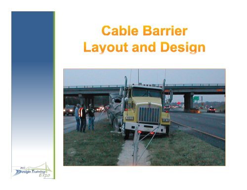
Cable Barrier Layout and Design - Florida Department of ...
Cable Barrier Layout and Design - Florida Department of ...
Cable Barrier Layout and Design - Florida Department of ...

Create successful ePaper yourself
Turn your PDF publications into a flip-book with our unique Google optimized e-Paper software.
John Mauthner, P.E. Rebecca Hatton<br />
<strong>Design</strong> St<strong>and</strong>ards Manager <strong>Design</strong> St<strong>and</strong>ards Specialist<br />
(850) 414‐4334 (850) 414‐4824<br />
John.Mauthner@dot.state.fl.us Rebecca.Hatton@dot.stste.fl.us<br />
2
COURSE OUTLINE<br />
1. An Introduction to <strong>Cable</strong> <strong>Barrier</strong>s<br />
2. History , Background, <strong>and</strong> Future Direction <strong>of</strong><br />
<strong>Cable</strong> <strong>Barrier</strong> Systems (NCHRP Project 22‐25)<br />
3. <strong>Layout</strong> <strong>and</strong> <strong>Design</strong> <strong>of</strong> <strong>Cable</strong> <strong>Barrier</strong> Systems<br />
3
<strong>Cable</strong> <strong>Barrier</strong> Systems<br />
Are<br />
Longitudinal g Roadside Safety y Devices<br />
Used to<br />
Contain <strong>and</strong>/or Redirect Errant Vehicles<br />
4
Can an Errant Vehicle Recover from a<br />
Run‐Off‐the‐Road Accident at this<br />
Location?<br />
5<br />
Let’s Explore the Possibility!<br />
Crash Test: <strong>Cable</strong> <strong>Barrier</strong> Shields a Drop‐Off Hazard
<strong>Cable</strong> <strong>Barrier</strong> Systems<br />
Have Been Used on America’s America s<br />
Highways g y <strong>and</strong> Byways y y<br />
For More Than<br />
65 Years!<br />
6
A Typical Low Tension <strong>Cable</strong> <strong>Barrier</strong> System<br />
8
Prior to 2000, 2000<br />
All <strong>Cable</strong> <strong>Barrier</strong> Systems<br />
In the United States were<br />
Low Tension Tension, Non‐Proprietary Non Proprietary Systems<br />
9
<strong>Florida</strong> <strong>Department</strong> p <strong>of</strong> Transportation p<br />
Uses<br />
High Tension “Weak‐Post” Pre‐Stretched<br />
<strong>Cable</strong> <strong>Barrier</strong> Systems y<br />
10
NCHRP Project 22‐25: 22 25:<br />
Nation‐Wide, High Tension <strong>Cable</strong><br />
<strong>Barrier</strong> Use is on the Rise<br />
All Manufacturers April 2006 April 2008<br />
Total Miles Installed 1,048 2,675<br />
From 2006 to 2008<br />
High Tension <strong>Cable</strong> <strong>Barrier</strong> Installations<br />
Increased by 155% Nationally<br />
11
Graph Depicts the Relationship between <strong>Cable</strong> <strong>Barrier</strong> Installations <strong>and</strong> the Reduction<br />
in Fatal Cross Median Crashes for I‐70 in Missouri.<br />
12
Determining Exclusion Zones<br />
For<br />
Lateral l Cbl <strong>Cable</strong> <strong>Barrier</strong> i Placement l<br />
13
Exclusion Zone for a 16’ Median on a 6:1 Cross Slope<br />
Vehicle<br />
Direction<br />
14<br />
GOOD<br />
3 feet<br />
BAD<br />
Test 2 Placement<br />
Test 1 Placement
V‐Shaped<br />
6:1 Medians <br />
Exclude <strong>Barrier</strong><br />
Placement 8’<br />
On Either Side<br />
15<br />
16 ft Median<br />
224 fft Median di<br />
32 ft Median<br />
40 ft Median<br />
48 ft Median
Average g Height g <strong>of</strong> “3 Wire Rope” p for TL‐3 <strong>Cable</strong> <strong>Barrier</strong> Systems: y<br />
Top = 30” Plus 1” Tolerance & Bottom = 20” Minus 1” Tolerance<br />
16
Lateral Dynamic Deflection <strong>of</strong> 3 Wire Rope Depends on:<br />
End Anchor Spacing (Length <strong>of</strong> Run),<br />
Post to Post Spacing,<br />
<strong>Cable</strong> <strong>Cable</strong> Tensioning. Tensioning<br />
17
Computer Crash Simulations Calibrated with<br />
18<br />
Crash Test Results:
Sample Over‐Ride Over Ride <strong>and</strong> Under‐Ride Under Ride Limit Plots<br />
OOverride id Li Limit it<br />
UUnder‐ride d id Limit Li it<br />
Median<br />
Pr<strong>of</strong>ile<br />
Yellow = 3 Wire Rope<br />
Red = Bad Placement<br />
(Exclusion Zone)<br />
19
Compare Crash Simulation Sequential Plots to Crash Test Video<br />
20
Compare Crash Simulation Sequential Plots to Crash Test Video<br />
21
Based on Vehicle Dynamics Analysis (VDA):<br />
-8ft 8 ft<br />
Under‐ride Criteria:<br />
6:1 V‐Shaped Slopes<br />
0 ft 4 ft<br />
20 ft 20 ft<br />
4 ft 0 ft<br />
Over‐ride Criteria:<br />
6:1 VV‐Shaped Shaped Slopes<br />
22
<strong>Layout</strong> <strong>and</strong> <strong>Design</strong>:<br />
1. High Tension <strong>Cable</strong> <strong>Barrier</strong> Systems<br />
2. Implementation Guidance<br />
33. AAnticipated i i dD <strong>Design</strong> i SSt<strong>and</strong>ards d d<br />
23
1. High Tension <strong>Cable</strong> <strong>Barrier</strong> Systems<br />
• <strong>Design</strong> Coordination Process<br />
• Guide Line Issues<br />
• Plans Production<br />
24
Coordination Steps to Process <strong>Cable</strong> <strong>Barrier</strong> <strong>Design</strong>s:<br />
1. <strong>Cable</strong> <strong>Barrier</strong> Maintenance Program Must be in Place<br />
22. CContact t tDi District t i t SSpecifications ifi ti Offi Office <strong>and</strong> d Obt Obtain i<br />
Developmental Specification, SECTION 540, HIGH TENSION<br />
CABLE BARRIER SYSTEM<br />
3. Contact the State Roadway <strong>Design</strong> Engineer, to Evaluate Your<br />
CConceptual t lD<strong>Design</strong> i <strong>and</strong> d tto Obt Obtain i PProject j tAApprovall David C. O’Hagan, P.E.<br />
(850) 414‐4283<br />
25
<strong>Design</strong> St<strong>and</strong>ard Drawings are Not Available, Available but<br />
Developmental Specification (Dev 540), <strong>and</strong><br />
<strong>Design</strong> Bulletin RDB 07‐08<br />
have been produced to coordinate the design<br />
process.<br />
26
Developmental Specification 540<br />
• Scroll Down to Dev540.pdf<br />
• Obtain <strong>Design</strong> Bulletin Instructions from the <strong>Design</strong> St<strong>and</strong>ards<br />
Website<br />
27
http://www.dot.state.fl.us/rddesign/updates/files/updatearchives.shtm
• FHWA Approved Proprietary High Tension <strong>Cable</strong> <strong>Barrier</strong>s<br />
• <strong>Cable</strong> <strong>Barrier</strong> Systems, include:<br />
3 cable bl systems = TL‐33<br />
4 cable systems = TL‐3 or TL‐4<br />
• Deflection Distances Depend on Post Spacing <strong>and</strong> Product<br />
Tables can be obtained from specific product manufacturers<br />
• Federal Oversight Projects Require FHWA Approval<br />
29
Gibraltar<br />
CASS Marion<br />
30
Safence Brifen<br />
31
Test Level 3 (TL‐3) ( ) Test Level 4 (TL‐4)<br />
32
Plans Production:<br />
• Plans Preparation Criteria<br />
• Plan l Set Components<br />
• <strong>Design</strong> Documentation<br />
33
Placement:<br />
• Min. 12’ Offset from Edge <strong>of</strong> Travel Way<br />
• 10 10:1 1 Slopes Sl are Preferred P f d<br />
• Can be placed p on shoulders or on slopes p<br />
“up to” 6:1<br />
• Slopes Steeper Than 6:1 Require State<br />
RRoadway d D<strong>Design</strong> i EEngineer i AApproval l<br />
34
• Median Placement, Placement cable barrier Shall NOT<br />
be in the region 8’ either side <strong>of</strong> the center ‘V’<br />
• Minimum System Length is 1000’<br />
• Approach <strong>and</strong> Trailing End Terminals should be<br />
ddesigned i diin th the same manner as guardrail d il<br />
– See Index 400<br />
35
• Provide Typical Sections for <strong>Cable</strong> Installations<br />
• Locate <strong>Cable</strong> <strong>Barrier</strong> Systems on Plan Sheets<br />
Label Label Begin Be in <strong>and</strong> End Stations with ith Offset<br />
Include any Necessary Alignment Data for<br />
Construction (such as Offsets, PC’s, PT’s, PI’s,<br />
Alignment Transitions, Radii, etc.)<br />
• Generate Special Details Sheets<br />
• Tbl Tabulate QQuantities i i<br />
36
• Summarize <strong>Cable</strong> <strong>Barrier</strong> Quantities on the<br />
Summary <strong>of</strong> Quantities Sheet by<br />
Station <strong>and</strong> Location<br />
• Tabulate all Segment Lengths <strong>and</strong> Show the<br />
Total Plan Quantity <strong>of</strong> <strong>Cable</strong> <strong>Barrier</strong> Required<br />
for the Project (to include End Terminals)<br />
37
Document Critical <strong>Design</strong> g Issues:<br />
• Typical Section Packages<br />
• Summary <strong>of</strong> Quantities<br />
• Engineers Construction Cost Estimate<br />
39
Implementation Guidance: Guidance<br />
Developmental Specification, Section 540<br />
Valid Pay Item Use<br />
Deliverable Requirements<br />
40
Developmental Specification, Section 540<br />
• Description<br />
• Materials<br />
• Train Installation Work Crew<br />
On‐Site Supervisor<br />
• Construction Requirements q<br />
• Method <strong>of</strong> Measurement<br />
• BBasis i <strong>of</strong> f PPayment<br />
41
Valid Pay Item Use:<br />
904‐540‐2 Socketed Post System, LF<br />
904‐540‐4 End Terminal, EA<br />
904‐540‐5 Reset Existing System, LF<br />
904 904‐540‐6 540 6 Reset Existing End Terminal Terminal, EA<br />
904‐540‐10 Relocate, LF<br />
42
Deliverable Requirements:<br />
• Follow Developmental Specification 540<br />
• Ensure Proper p Pay y Item Use<br />
• Require a Soils Specific <strong>Design</strong> for End Terminals<br />
• Request Shop Drawings for Product Specific Installations<br />
• Request Approvals for Federal Oversight Projects from FHWA<br />
<strong>and</strong> add to Statewide Work Plan<br />
• Provide Final Plans to Central Office, Roadway <strong>Design</strong><br />
43
Anticipated <strong>Design</strong> St<strong>and</strong>ards<br />
• <strong>Cable</strong> <strong>Barrier</strong> Critical Issues<br />
• Implementation <strong>of</strong> Research Findings<br />
• In‐service Performance Evaluations<br />
• Proposed <strong>Design</strong> Criteria <strong>and</strong> <strong>Design</strong> St<strong>and</strong>ards<br />
44
<strong>Cable</strong> <strong>Barrier</strong> Critical Issues:<br />
• <strong>Cable</strong> <strong>Barrier</strong> Lateral Placement<br />
• <strong>Cable</strong> <strong>Barrier</strong> Deflection Criteria<br />
• End Terminal <strong>and</strong> Post Anchoring Systems<br />
• Interconnection with Other <strong>Barrier</strong> Systems<br />
45
<strong>Cable</strong> <strong>Barrier</strong> Critical Issues (Continued):<br />
( )<br />
• Construction Tolerances;<br />
• Top Height Requirements ( + 1”)<br />
• Bottom Height Requirements (‐ 1”)<br />
• Horizontal Curve Placement Guidance<br />
• Installation vs. Maintenance Costs<br />
46
• MASH <strong>Cable</strong> <strong>Barrier</strong> Test Requirements<br />
– “Assessment <strong>of</strong> Vehicle Dynamics on Sloped Medians<br />
for New MASH <strong>Cable</strong> <strong>Barrier</strong> Test Criteria Criteria”<br />
• NCHRP Project 22 –25<br />
– “Development <strong>of</strong> Guidance for the Selection, Use, <strong>and</strong> Maintenance <strong>of</strong><br />
<strong>Cable</strong> <strong>Barrier</strong> Systems”<br />
• FDOT Research Contract No. BDK 80 977‐19<br />
– “I “In‐Service S i Performance P f Evaluation E l ti <strong>of</strong> f Median Mdi <strong>Cable</strong> Cbl<strong>Barrier</strong> B i iin <strong>Florida</strong>” Fl id ”<br />
47
• Evaluate <strong>and</strong> Monitor In In‐service service Performance<br />
– “In‐Service Performance Evaluation<br />
<strong>of</strong> Median <strong>Cable</strong> <strong>Barrier</strong> in <strong>Florida</strong>”<br />
• Based on Installation Costs (Cost/Mile)<br />
• Based on Maintenance Costs (Average<br />
Cost/Repair) / p )<br />
48
• Derive Permanent Specifications –<br />
• Compile Foundation <strong>Design</strong> Parameters (Soils) –<br />
• Establish Permanent Pay Items –<br />
• Plans Preparation Manual Update –<br />
• Update Chapter 4, PPM Vol. I<br />
• Establish Guidelines for <strong>Cable</strong> <strong>Barrier</strong> <strong>Design</strong><br />
• Update Exhibits with Examples <strong>of</strong> <strong>Cable</strong> <strong>Barrier</strong> Systems<br />
49
• Develop p Proposed p St<strong>and</strong>ard Indexes<br />
• Draft Generic High Tension <strong>Cable</strong> System Drawings<br />
• Organize Drawings within the Index 400 Series (Guardrail)<br />
• Reference Specifications Specifications, Estimates Estimates, <strong>and</strong> <strong>Design</strong> Guidelines<br />
(AASHTO, MASH, RDG, HSM, etc.)<br />
• Update Roadside <strong>Barrier</strong> Training ‐ Based on New Criteria<br />
<strong>and</strong> St<strong>and</strong>ards<br />
50
Rebecca Hatton – <strong>Design</strong> g St<strong>and</strong>ards Specialist p<br />
(850) 414‐4824<br />
Rebecca.Hatton@dot.state.fl.us<br />
Patrick Overton –<strong>Design</strong> St<strong>and</strong>ards Engineer<br />
(850) 414‐4348<br />
Patrick.Overton@dot.state.fl.us<br />
John Mauthner – <strong>Design</strong> St<strong>and</strong>ards Manager<br />
(850) 414‐4334<br />
John.Mauthner@dot.state.fl.us<br />
51