WS Procs 975 x 65
WS Procs 975 x 65
WS Procs 975 x 65

You also want an ePaper? Increase the reach of your titles
YUMPU automatically turns print PDFs into web optimized ePapers that Google loves.
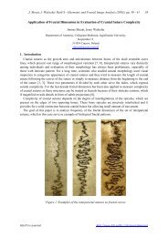
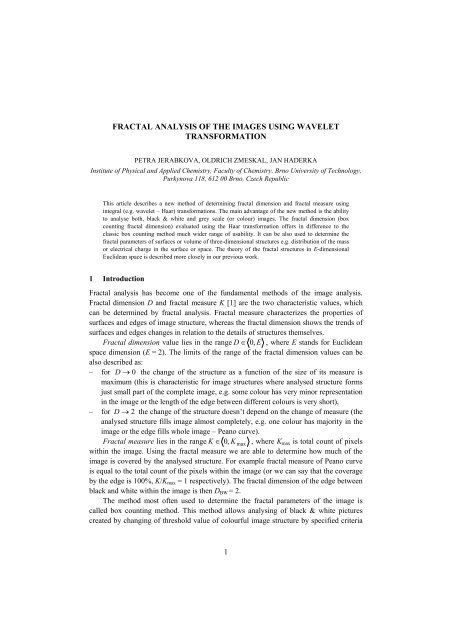
FRACTAL ANALYSIS OF THE IMAGES USING WAVELET<br />
TRANSFORMATION<br />
PETRA JERABKOVA, OLDRICH ZMESKAL, JAN HADERKA<br />
Institute of Physical and Applied Chemistry, Faculty of Chemistry, Brno University of Technology,<br />
Purkynova 118, 612 00 Brno, Czech Republic<br />
This article describes a new method of determining fractal dimension and fractal measure using<br />
integral (e.g. wavelet – Haar) transformations. The main advantage of the new method is the ability<br />
to analyse both, black & white and grey scale (or colour) images. The fractal dimension (box<br />
counting fractal dimension) evaluated using the Haar transformation offers in difference to the<br />
classic box counting method much wider range of usability. It can be also used to determine the<br />
fractal parameters of surfaces or volume of three-dimensional structures e.g. distribution of the mass<br />
or electrical charge in the surface or space. The theory of the fractal structures in E-dimensional<br />
Euclidean space is described more closely in our previous work.<br />
1 Introduction<br />
Fractal analysis has become one of the fundamental methods of the image analysis.<br />
Fractal dimension D and fractal measure K [1] are the two characteristic values, which<br />
can be determined by fractal analysis. Fractal measure characterizes the properties of<br />
surfaces and edges of image structure, whereas the fractal dimension shows the trends of<br />
surfaces and edges changes in relation to the details of structures themselves.<br />
Fractal dimension value lies in the range D ∈ 0,<br />
E , where E stands for Euclidean<br />
space dimension (E = 2). The limits of the range of the fractal dimension values can be<br />
also described as:<br />
– for D → 0 the change of the structure as a function of the size of its measure is<br />
maximum (this is characteristic for image structures where analysed structure forms<br />
just small part of the complete image, e.g. some colour has very minor representation<br />
in the image or the length of the edge between different colours is very short),<br />
– for D → 2 the change of the structure doesn’t depend on the change of measure (the<br />
analysed structure fills image almost completely, e.g. one colour has majority in the<br />
image or the edge fills whole image – Peano curve).<br />
Fractal measure lies in the range K ∈ 0, K max , where Kmax is total count of pixels<br />
within the image. Using the fractal measure we are able to determine how much of the<br />
image is covered by the analysed structure. For example fractal measure of Peano curve<br />
is equal to the total count of the pixels within the image (or we can say that the coverage<br />
by the edge is 100%, K/Kmax = 1 respectively). The fractal dimension of the edge between<br />
black and white within the image is then DBW = 2.<br />
The method most often used to determine the fractal parameters of the image is<br />
called box counting method. This method allows analysing of black & white pictures<br />
created by changing of threshold value of colourful image structure by specified criteria<br />
1
2<br />
(e.g. on RGB, HSV, HSB space) – the thresholding. The results of fractal analysis (using<br />
the box counting method) are box counting fractal dimension and box counting fractal<br />
measure.<br />
This article describes a new method of determining fractal dimension and fractal<br />
measure using integral (wavelet – Haar) transformation. The main advantage of the new<br />
method is the ability to analyse grey scale (or colour) images without lengthy<br />
thresholding and calculating the box counting fractal dimension D and fractal measure K<br />
for each thresholded image in the set.<br />
More detailed results of the analysis using this new method can be found on our web<br />
pages http://www.fch.vutbr.cz/lectures/imagesci. The interpretation of the results<br />
obtained from the black & white image analysis (using the new method) remains the<br />
same as from the box counting method of black & white pictures. The main disadvantage<br />
of the new method may be seen in smaller set of data used for regression analysis as in<br />
box counting method. There can be obtained only 10 independent values per image with<br />
1024 × 1024 pixels matrix that can be used to determine the fractal dimension D and<br />
fractal measure K. Such disadvantage can be turned into an advantage as removing<br />
redundant use of pixels minimizes the error introduced by reusing the values of wrongly<br />
determined values of pixels.<br />
2 Box counting method<br />
Analysis of black & white images is usually performed by box counting method [2].<br />
Figure 1 shows how is the method used. A net of different size (1 × 1, 2 × 2, 3 × 3, 4 × 4,<br />
etc. pixels) is placed on the analysed image and the total count of black boxes NB, white<br />
boxes NW and black&white NBW boxes is determined.<br />
Figure 1. Determination of the fractal measure and fractal dimension using the box counting method.<br />
The function of the count of pixels on the net size ε = 1/n, where ε is the size of<br />
pixels and n is the scale, is used to determine three different types of fractal dimension:<br />
black area, white area and their edge (DBBW, DWBW, DBW). To calculate the dimension<br />
DBBW and DWBW, the count of black and black & white (BW) N BBW = NB<br />
+ NBW<br />
or<br />
white and black & white (BW) N WBW = NW<br />
+ NBW<br />
boxes is utilised. The variation of<br />
fractal dimension with the count of boxes can be written
N<br />
−D<br />
D<br />
( ε ) = K ⋅ε<br />
N( n)<br />
= K ⋅n<br />
,<br />
3<br />
, (1)<br />
respectively, where K is the fractal measure and D is the fractal dimension (without their<br />
indexes). From these terms the fractal dimension is given by the slope of function (1)<br />
d ln N<br />
D = −<br />
d lnε<br />
( ε ) d ln N(<br />
n)<br />
=<br />
d ln n<br />
The area filled by the examined set (points) can be expressed as<br />
S<br />
( n)<br />
and the length of lines in figure as<br />
L<br />
( n)<br />
N<br />
=<br />
n<br />
( n)<br />
D−2<br />
2<br />
N<br />
=<br />
n<br />
= K ⋅ n<br />
( n)<br />
D−1<br />
= K ⋅ n<br />
. (2)<br />
respectively.<br />
The Figure 2 shows the dependency obtained from the model image of a tree for<br />
black & white squares. The image shows that the function is almost linear (structure of<br />
the image is fractal). There is clearly a visible error for small sizes of the boxes<br />
(introduced by the interpolation of values) and also error for the very big sizes of the<br />
boxes (introduced by saturation of the number of boxes).<br />
log(N BW)<br />
8<br />
7<br />
6<br />
5<br />
4<br />
3<br />
2<br />
1<br />
0<br />
Square numbers<br />
WM<br />
BCM<br />
-6 -5 -4 -3 -2 -1 0<br />
log(n )<br />
Figure 2. Determination of the fractal measure and fractal dimension using the box counting (see Figure 1) and<br />
for wavelet method (see Figure 3 - Figure 5).<br />
Acquired fractal measures KBBW, KWBW, KBW can be used for determination of the<br />
black – SB (white – SW respectively) areas of threshold figure<br />
S<br />
B<br />
=<br />
K<br />
BBW<br />
KBBW<br />
− KBW<br />
+ K − K<br />
WBW<br />
BW<br />
,<br />
W<br />
=<br />
K<br />
and the length of divided lines L of threshold figure<br />
S<br />
K WBW − KBW<br />
+ K − K<br />
BBW<br />
WBW<br />
BW<br />
(3)<br />
(4)<br />
(5)
4<br />
L =<br />
K<br />
BBW<br />
K<br />
+ K<br />
BW<br />
WBW<br />
− K<br />
BW<br />
. (6)<br />
The results are taken in relative units (multiplied by 100 in percent). Results in<br />
pixels can be taken after multiplying this number by area size of the figure (Kmax).<br />
3 Wavelet method<br />
The description of the box counting method shows that it is variation of integral methods.<br />
Using that knowledge the authors tried to find the best integral transformation that can be<br />
used to evaluate the fractal parameters of image structures. The driving force of our<br />
effort was to simplify the algorithm for determination of the fractal dimension and to<br />
extend the range of possible interpretation of the results. It was found that already very<br />
simple wavelet transformation – Haar transformation [3] gives us the identical results of<br />
values of fractal parameters (for threshold figure) as the box counting method.<br />
Haar transformation (HT) is linear orthogonal transformation with signum function<br />
(rectangle function) base. The HT transforms real image f(m, n) into discreet spectrum<br />
represented by real function F(k, l)<br />
( , ) = l k F<br />
− N 1 N −1<br />
∑∑<br />
m=<br />
0 n=<br />
0<br />
( , ) h n m f<br />
m, k n,<br />
l h<br />
where hn,k and hm,l are the coefficients of so called Haar matrix HN<br />
H<br />
0<br />
⎡1<br />
1⎤<br />
= , H1<br />
= ⎢ ,<br />
1 1<br />
⎥ H<br />
⎣ − ⎦<br />
1 2<br />
⎡1<br />
⎢<br />
1<br />
= ⎢<br />
⎢1<br />
⎢<br />
⎣0<br />
1<br />
1<br />
−1<br />
Haar matrix Hn is the order of 2 n (2 n dimensional matrix).<br />
0<br />
, (7)<br />
1<br />
−1<br />
0<br />
1<br />
1⎤<br />
−1<br />
⎥<br />
⎥<br />
0⎥<br />
⎥<br />
−1⎦<br />
2 × 2 4 × 4 8 × 8<br />
, ...<br />
. (8)<br />
Figure 3. Spectra of image structure determined by Haar transformation of image from Figure 1 (wavelet<br />
method)<br />
The method requires (like the Fast Fourier Transformation) a square matrix of data<br />
given by square of two. Figure 3 show the resulting spectra and images of the tree<br />
(Figure 1) of size 1024 × 1024 pixels. The spectra are calculated using the matrix of<br />
Haar transformation (transformation base) of size (matrix and image) 1024 × 1024
pixels. Figure 3 shows top left corner cut from the complete matrix (2 × 2, 4 × 4, 8 × 8<br />
pixels). The top left item of the matrix stores information about amount of black pixels<br />
within the image. The information about count of black pixels in each quarter of the<br />
image can be then determined from the matrix obtained by the reverse Haar<br />
transformation (such matrix is then half of the size of the original matrix), see Figure 4.<br />
The Figure 5 shows information about count of black pixels in the quarter of the<br />
matrix. Shades of grey on Figure 4 are equivalent to the count of black & white (BW)<br />
pixels in the quarter. Fractal dimensions of black, white and black & white can be<br />
determined as it was possible when using box counting method (DBBW, DWBW, DBW). The<br />
parameters obtained by our method are identical to parameters determined by the box<br />
counting method for matrixes of 2 n × 2 n (1 × 1, 2 × 2, 4 × 4, 8 × 8, etc.) pixels.<br />
64 × 64 32 × 32 16 × 16<br />
Figure 4. Determination of the fractal measure and fractal dimension using wavelet method (grey scale squares)<br />
64 × 64 32 × 32 16 × 16<br />
Figure 5. Determination of the fractal measure and fractal dimension using wavelet method (tresholded squares)<br />
The function of count of black & white squares is displayed in Figure 2 (these<br />
determine the characteristic of the interface between black and white areas in the image).<br />
The fractal dimension determined by the box counting method was DBW = 1.1053. The<br />
graph displayed shows that the function is not linear. The exact derivative of the function<br />
is shown in Figure 2 right. Error in the big squares area (on the right side of the graph) is<br />
caused by error of applying grid on the image (error is approximately same for both<br />
methods). Error in the small squares area (left side of the graph) is caused by wrong<br />
interpolation of the data. Inflection point of the graph curve is exactly at the point equal<br />
to the value of the fractal dimension of the structure.<br />
The acquired fractal measures KBBW, KWBW, KBW can be used for determination of<br />
black and white areas of figure and the dividing lines lengths using the same equations as<br />
for box counting method, see Eqs. (5) and (6).<br />
5
6<br />
4 Algorithm of fractal parameters calculation using the Haar transformation<br />
The method of fractal parameters calculation described in the previous chapter is<br />
relatively time-consuming. It requires performing the direct Haar transformation of<br />
analysed picture (with size 2 n × 2 n pixels) and (n−1) reverse Haar transformations of<br />
spectrums, which were previously filtered by low-pass filtering (n−1) × (n−1), (n−2) ×<br />
(n−2), ... pixels. The fractal parameters are then calculated using standard technique (like<br />
box-counting method) from the sequence of the obtained pictures with flattened details.<br />
It was found by detail problem analysis that the algorithm above can be simplified<br />
by simple adding of four adjacent pixels (which have values 0 and 1 in the original<br />
thresholded picture). After the first step we obtain picture of size 2 n−1 × 2 n−1 pixels with<br />
values from 0 to 4, after the second step the picture will have its size 2 n−2 × 2 n−2 pixels<br />
with values from 0 to 16, etc. The NB of the picture is then the number of pixels with<br />
value 0, the NW is number of pixels with maximal value (i.e. 1, 4, 16, ... , 2 2n ) and the<br />
NBW is the number of the rest of pixels. The log N = f(log n) dependency allows to<br />
determine the fractal dimension and fractal measure of the tresholded picture using the<br />
standard techniques. The analysis of a black box gives fractal dimension DW = 0 (number<br />
of white pixels is always zero) whereas the analysis of a box containing only white pixels<br />
results in DW = 2.<br />
5 Analysis of three - dimensional structures<br />
In the case of analysing a grey scale picture, it is supposable, that the shade represents a<br />
profile of a three-dimensional structure (see e.g. Figure 6). In this case the particular<br />
pixels have values from 0 (black) to 255 (white). Adding of values of foursome pixels<br />
results in picture of 2 n−1 × 2 n−1 pixels size with values from 0 to 1020. After the second<br />
iteration a 2 n−2 × 2 n−2 pixels sized picture with values from 0 to 2040 is obtained, etc.<br />
2D projection 3D projection<br />
Figure 6. Determination of the fractal measure and fractal dimension of 3D structure (fractal dimension of<br />
surface) using wavelet method<br />
The NB of each individual picture is then the number of pixels with value 0, the NW<br />
is the number of pixels with maximal value (i.e. 1020, 4080, ... , 255 · 2 2n ) and the NBW is
the number of the remaining of pixels. The log N = f(log n) dependency allows to<br />
determine the fractal dimension and fractal measure of the tresholded picture using the<br />
standard techniques. The analysis of a black box gives fractal dimension DW = 0 (number<br />
of white pixels is always zero) whereas the analysis of a box containing only white pixels<br />
results in DW = 3.<br />
The volume filled by the examined set (points) can be expressed as<br />
V<br />
( n)<br />
N<br />
=<br />
n<br />
( n)<br />
D−3<br />
3<br />
= K ⋅ n<br />
. (9)<br />
The following equations determines the areas under (VB) and above (VW) of the 3D<br />
object surface<br />
V<br />
and area size S<br />
B<br />
=<br />
K<br />
BBW<br />
K BBW − K BW<br />
+ K − K<br />
WBW<br />
S =<br />
K<br />
BW<br />
BBW<br />
V<br />
,<br />
K<br />
+ K<br />
W<br />
BW<br />
WBW<br />
=<br />
K<br />
− K<br />
K WBW − K BW<br />
+ K − K<br />
in relative units (in percent respectively). Volumes and areas in volume pixels (voxels)<br />
can be obtained by multiplying the results by the maximal volume. It depends on the area<br />
size of figure and its colour depth (e.g. for eight bit depth is given by multiplying by the<br />
number 2 1 255 ). Coefficient which determines how many times is the fractal<br />
surface area higher then the horizontal surface area (size of figure) can be also calculated.<br />
8<br />
− =<br />
log(N GRAY)<br />
18<br />
16<br />
14<br />
12<br />
10<br />
8<br />
6<br />
4<br />
2<br />
0<br />
-2<br />
BBW<br />
BW<br />
Square numbers<br />
WBW<br />
-6 -5 -4 -3 -2 -1 0<br />
log(n )<br />
Figure 7. Determination of the fractal measure and fractal dimension of 3D structure (fractal dimension of<br />
surface) using wavelet method<br />
Fractal dimension of surface of a fractal structure in Figure 6 is DBW = 2.263. Fractal<br />
dimension of the structure volume was found to be DBBW = 2.877 and fractal dimension<br />
of the surrounding volume is DWBW = 2.900. Volumes of the object and surroundings<br />
have the fractal dimension near the value of the Euclidean dimension of volume E = 3.<br />
BW<br />
WM<br />
7<br />
(10)<br />
(11)
8<br />
This implies that the object has nearly the Euclidean shape. Fractal dimension of the<br />
surface is significantly bigger than the Euclidean dimension of plane E = 2 and has<br />
therefore evidently fractal nature. The fractal measure of the interface determines the size<br />
of the fractal structure surface (in pixels) and is KBW/Kmax = 362.79 % of the image’s<br />
planar surface, where Kmax = (512 × 512) pixels. Fractal measure of the structure volume<br />
is KBBW/Kmax = 40.97 % and its surroundings KWBW/Kmax = 59.03 %, where<br />
Kmax = (512 × 512 × 255) voxels (volume pixels). The fractal measure of the interface<br />
tells us therefore that the surface of the fractal structure is more than three times larger<br />
than the surface of plane.<br />
6 Conclusion<br />
It is worth mentioning that the fractal dimension of the deterministic fractal structures<br />
(e.g. Sierpinsky carpet) is immutable in the whole range of sizes of the net applied on the<br />
image using box counting method (or level of filter using wavelet – Haar –<br />
transformation) and is the same as the theoretical fractal dimension value. Similar fractal<br />
dimension values were also obtained using other types of integral, e.g. the Fourier<br />
transformations. In this case the values of fractal parameters are influenced by broader<br />
vicinity (step function is replaced by harmonic function).<br />
The fractal dimension evaluated using the Haar transformation offers in contrast to<br />
the classic box counting method a much wider range of usability. The method can also be<br />
used to determine the fractal dimension of colour structures (e.g. greyscale or full colour<br />
images). This also allows determining the fractal dimensions of surfaces specified by<br />
shades of grey or colour components. This can be also used to determine the fractal<br />
parameters of surfaces or three-dimensional structures like distribution of the mass in the<br />
space or electrical potential in space. The theory of the fractal structures in Edimensional<br />
Euclidean space is described more closely e.g. in [4, 5].<br />
Software for fractal analysis of the images is provided free on the Internet<br />
http://www.fch.vutbr.cz/lectures/imagesci.<br />
Literature<br />
1 . B. B. Mandelbrot, Fractal geometry of nature. New York: W.H. Freeman and Co.<br />
(1983)<br />
2 . M. J. Barnsley, Fractals everywhere, New York:Academic Press Inc. (1993)<br />
3 . G. Strang, Wavelets Transforms versus Fourier Transforms, Bulletin of the<br />
American Mathematical Society, 28, 288 (1993)<br />
4 . O. Zmeskal, M. Nezadal, M. Buchnicek, Chaos, Solitons & Fractals, 17, 113 (2003)<br />
5 . O. Zmeskal, M. Nezadal, M. Buchnicek, Chaos, Solitons & Fractals, 19, 1013 (2004)