

UltraVoice Manual - Alerting & Notification
UltraVoice Manual - Alerting & Notification
UltraVoice Manual - Alerting & Notification

Create successful ePaper yourself
Turn your PDF publications into a flip-book with our unique Google optimized e-Paper software.
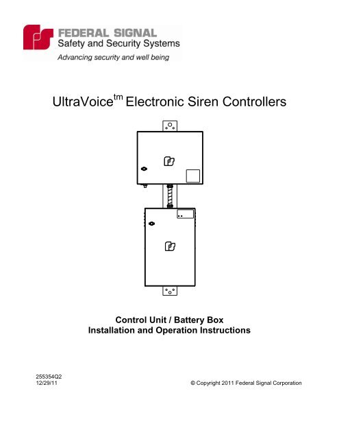
<strong>UltraVoice</strong> tm Electronic Siren Controllers<br />
Control Unit / Battery Box<br />
Installation and Operation Instructions<br />
255354Q2<br />
12/29/11 © Copyright 2011 Federal Signal Corporation
Federal Signal <strong>UltraVoice</strong><br />
Installation and Operation <strong>Manual</strong><br />
SAFETY NOTICES<br />
People‟s lives depend on your selection of suitable equipment and installation sites and<br />
your safe installation, service, and operation of our products. Federal Signal recommends the<br />
following publications from the Federal Emergency Management Agency for assistance with<br />
planning an outdoor warning system: 1. The “Outdoor Warning Guide (CPG 1-17), 2. “Civil<br />
Preparedness, Principles of Warning” (CPG 1-14), 3. FEMA-REP-1, Appendix 3 (Nuclear Plant<br />
Guideline), and 4. FEMA-REP-10 (Nuclear Plant Guideline). Contact Federal Signal‟s Technical<br />
Support Center at: http://www.alertnotification.com or 1-800-524-3021 for further information about<br />
these publications.<br />
It is important to read, understand and follow all instructions shipped with this product. In addition,<br />
listed below are some other important safety instructions and precautions you should follow.<br />
PLANNING<br />
If suitable warning equipment is not selected, the installation site for the siren is not selected<br />
properly or the siren is not installed properly, it may not produce the intended optimum audible<br />
warning. Follow Federal Emergency Management Agency (FEMA) recommendations.<br />
If sirens are not activated in a timely manner when an emergency condition exists, they cannot<br />
provide the intended audible warning. It is imperative that knowledgeable people, who are<br />
provided with the necessary information, are available at all times to authorize the activation of<br />
the sirens.<br />
When sirens are used out of doors, people indoors may not be able to hear the warning<br />
signals. Separate warning devices or procedures may be needed to effectively warn people<br />
indoors.<br />
The sound output of sirens is capable of causing permanent hearing damage. To prevent<br />
excessive exposure, carefully plan siren placement, post warnings, and restrict access to areas<br />
near sirens.<br />
Activating the sirens may not result in people taking the desired actions if those to be warned<br />
are not properly trained about the meaning of siren sounds. Siren users should follow FEMA<br />
recommendations and instruct those to be warned of correct actions to be taken.<br />
A siren that does not work will not provide any warning. After installation, service, or<br />
maintenance, test the siren system to confirm that it is operating properly. Test the system<br />
regularly to confirm that it will be operational in an emergency.<br />
If future service and operating personnel do not have these instructions to refer to, the siren<br />
system may not provide the intended audible warning and service personnel may be exposed<br />
to death, permanent hearing loss, or other bodily injury. File these instructions in a safe place<br />
and refer to them periodically. Give a copy of these instructions to new recruits and trainees.<br />
Also give a copy to anyone who is going to service or repair the siren.<br />
2
Federal Signal <strong>UltraVoice</strong><br />
Installation and Operation <strong>Manual</strong><br />
SAFETY NOTICES<br />
People‟s lives depend on your safe installation, service and operation of our products. It is<br />
important to read, understand and follow all instructions shipped with this product. In addition,<br />
listed below are some other important safety instructions and precautions you should follow:<br />
INSTALLATION & SERVICE<br />
Electrocution or severe personal injury can occur when performing various installation and<br />
service functions such as making electrical connections, drilling holes, or lifting equipment.<br />
Therefore experienced electricians in accordance with national, state and any other electrical<br />
codes having jurisdiction should perform installation. All work should be performed under the<br />
direction of the installation or service crew safety foreman.<br />
The sound output of sirens is capable of causing permanent hearing damage. To prevent<br />
excessive exposure, carefully plan siren placement, post warnings and restrict access to areas<br />
near the sirens. Sirens may be operated from remote control points. Whenever possible,<br />
disconnect all siren power including batteries before working near the siren.<br />
After installation or service, test the siren system to confirm that it is operating properly. Test<br />
the system regularly to confirm that it will be operational in an emergency.<br />
If future service personnel do not have these warnings and all other instructions shipped with<br />
the equipment to refer to, the siren system may not provide the intended audible warning and<br />
service personnel may be exposed to death, permanent hearing loss, or other bodily injury.<br />
File these instructions in a safe place and refer to them periodically. Give a copy of these<br />
instructions to new recruits and trainees. Also, give a copy to anyone who is going to service<br />
or repair the sirens. For additional copies, call the Federal Warning Systems Customer Care<br />
Center at 800-524-3021 or write to them at 2645 Federal Signal Drive, University Park, IL<br />
60484.<br />
OPERATION<br />
Failure to understand the capabilities and limitations of your siren system could result in<br />
permanent hearing loss, other serious injuries or death to persons too close to the sirens when<br />
you activate them or to those you need to warn. Carefully read and thoroughly understand all<br />
safety notices in this manual and all operations-related-items in all instruction manuals shipped<br />
with equipment. Thoroughly discuss all contingency plans with those responsible for warning<br />
people in your community, company, or jurisdiction.<br />
3
Federal Signal <strong>UltraVoice</strong><br />
Installation and Operation <strong>Manual</strong><br />
Limited Warranty<br />
The Federal Warning Systems Division of Federal Signal Corporation warrants each new<br />
product to be free from defects in material and workmanship, under normal use and service,<br />
for a period of two years on parts replacement and factory-performed labor (one year for<br />
Informer, EAS, and Federal software products) from the date of delivery to the first userpurchaser.<br />
Federal Warning Systems warrants every 2001 & Eclipse Siren (Top of pole<br />
only) to be free from defects in material, per our standard warranty, under normal use and<br />
service for a period of five years on parts replacement.<br />
During this warranty period, the obligation of Federal is limited to repairing or replacing, as<br />
Federal may elect, any part or parts of such product which after examination by Federal<br />
discloses to be defective in material and/or workmanship.<br />
Federal will provide warranty for any unit which is delivered, transported prepaid, to the<br />
Federal factory or designated authorized warranty service center for examination and such<br />
examination reveals a defect in material and/or workmanship.<br />
This warranty does not cover travel expenses, the cost of specialized equipment for gaining<br />
access to the product, or labor changes for removal and re-installation of the product. The<br />
Federal Signal Corporation warranty shall not apply to components or accessories that have<br />
a separate warranty by the original manufacturer, such as, but not limited to, batteries.<br />
Federal will provide on-site warranty service during the first 60-days after the completion of<br />
the installation, when Federal has provided a turn-key installation including optimization<br />
and/or commissioning services.<br />
This warranty does not extend to any unit which has been subjected to abuse, misuse,<br />
improper installation or which has been inadequately maintained, nor to units which have<br />
problems related to service or modification at any facility other than Federal factory or<br />
authorized warranty service centers. Moreover, Federal shall have no liability with respect to<br />
defects arising in Products through any cause other than ordinary use (such as, for example,<br />
accident, fire, lightning, water damage, or other remaining acts of god).<br />
THERE ARE NO OTHER WARRANTIES, EXPRESSED OR IMPLIED, INCLUDING BUT<br />
NOT LIMITED TO, ANY IMPLIED WARRANTIES OF MERCHANTABILITY OR FITNESS<br />
FOR A PARTICULAR PURPOSE. IN NO EVENT SHALL FEDERAL BE LIABLE FOR ANY<br />
LOSS OF PROFITS OR ANY INDIRECT OR CONSEQUENTIAL DAMAGES ARISING OUT<br />
OF ANY SUCH DEFECT IN MATERIAL WORKMANSHIP.<br />
2645 Federal Signal Drive, University Park, IL 60484<br />
Phone: (800) 524-3021 Fax: (708) 534-4865<br />
Website: http://www.alertnotification.com<br />
4
Federal Signal <strong>UltraVoice</strong><br />
Installation and Operation <strong>Manual</strong><br />
TABLE OF CONTENTS<br />
Section Page<br />
SECTION I - GENERAL DESCRIPTION<br />
1.1 Introduction ............................................................................................................... 8<br />
1.2 Configuration ......................................................................................................... 10<br />
1.3 User Programs ....................................................................................................... 11<br />
1.4 Programming Methods .......................................................................................... 13<br />
1.5 Status Monitoring ................................................................................................... 13<br />
SECTION II - SPECIFICATIONS<br />
2.0 Electrical ................................................................................................................ 15<br />
2.1 Charger .................................................................................................................. 15<br />
2.2 Battery ................................................................................................................... 16<br />
2.3 Serial & I2C Port .................................................................................................... 16<br />
2.4 Radio Communication ........................................................................................... 17<br />
2.5 Signaling Format .................................................................................................... 18<br />
2.6 Relay Output .......................................................................................................... 18<br />
2.7 600-Ohm Balanced Line Port ................................................................................ 18<br />
2.8 Remote Activation, Sensor, and Direction Inputs ................................................... 19<br />
2.9 Front Panel Controls, Jacks, Switches and Indicators ........................................... 19<br />
2.10 Expansion Slot ....................................................................................................... 22<br />
2.11 I 2 C ......................................................................................................................... 22<br />
2.12 Audio Output to Amplifiers ..................................................................................... 23<br />
2.13 Audio Power Amplifier Modules Model (UV400) .................................................... 23<br />
2.14 Environmental ........................................................................................................ 24<br />
2.15 Physical ................................................................................................................. 24<br />
SECTION III - ELECTRONIC SIREN CONTROL OPERATION<br />
3.0 Hardware General Description .............................................................................. 25<br />
3.1 <strong>Manual</strong> Activation .................................................................................................. 25<br />
3.2 Local Public Address ............................................................................................. 26<br />
3.3 Relay Output .......................................................................................................... 26<br />
3.4 600-Ohm Input ....................................................................................................... 26<br />
3.5 24 VDC Supply ...................................................................................................... 26<br />
3.6 Remote Landline Activation ................................................................................... 26<br />
3.7 Sensor Inputs ........................................................................................................ 27<br />
3.8 Isolated Supply ...................................................................................................... 28<br />
3.9 Rotation Sensor ..................................................................................................... 28<br />
3.10 Battery Charger ..................................................................................................... 28<br />
5
SECTION IV - SYSTEM PLANNING<br />
Federal Signal <strong>UltraVoice</strong><br />
Installation and Operation <strong>Manual</strong><br />
4.0 Control Unit ............................................................................................................ 29<br />
4.1 Siren and Control Location .................................................................................... 29<br />
SECTION V - INSTALLATION<br />
5.0 Siren Controller Installation .................................................................................... 30<br />
5.1 Electrical Connections ........................................................................................... 35<br />
5.2 Other Connection Options ..................................................................................... 42<br />
5.3 Control Unit Connector Configuration .................................................................... 42<br />
5.4 Yagi Antenna Installation ....................................................................................... 47<br />
5.5 Final VSWR Tuning ............................................................................................... 47<br />
5.6 Mount Yagi Antenna .............................................................................................. 50<br />
5.7 OMNI Antenna Installation ..................................................................................... 50<br />
SECTION VI - PRE-OPERATION CHECKOUT AND TEST<br />
6.0 Amplifier and Speaker Pre-Operation Checkout .................................................... 55<br />
6.1 Initial Checkout ...................................................................................................... 56<br />
SECTION VII - MAINTENANCE<br />
7.0 General .................................................................................................................. 59<br />
7.1 Control Unit Preventive Maintenance .................................................................... 59<br />
7.2 General Maintenance ............................................................................................ 60<br />
7.3 Adjustment Procedure for 2005026,2005027 or 2005240 1-Way Radio Receiver . 61<br />
7.4 Adjustment Procedure for a Two-Way Radio Receiver .......................................... 65<br />
7.5 600-Ohm Adjustment Procedure for Activation Audio ............................................ 66<br />
7.6 600-Ohm Adjustment Procedure for External Audio Source .................................. 66<br />
7.7 Troubleshooting ..................................................................................................... 67<br />
SECTION VIII - OPTIONS<br />
8.0 Radio Control ......................................................................................................... 69<br />
8.1 Two-Way Sensor Package .................................................................................... 69<br />
8.2 Local Quiet Test ..................................................................................................... 69<br />
8.3 Digital Voice ........................................................................................................... 70<br />
8.4 Installation of Other Manufacturers‟ Receivers in <strong>UltraVoice</strong> Siren Controllers ..... 71<br />
8.5 Serial Port Control ................................................................................................. 72<br />
8.6 Status Monitoring ................................................................................................... 72<br />
8.7 DTMF Report Format ............................................................................................. 73<br />
8.8 Serial Report Format ............................................................................................. 76<br />
8.9 Solar Power Option ................................................................................................ 78<br />
8.10 UV25ST Option ...................................................................................................... 78<br />
8.11 FS-SINAD Option .................................................................................................. 79<br />
8.12 Model UVTD-IP ..................................................................................................... 79<br />
8.13 UV6048 Satellite Models ....................................................................................... 83<br />
6
SECTION IX – APPENDIX A<br />
Federal Signal <strong>UltraVoice</strong><br />
Installation and Operation <strong>Manual</strong><br />
Speaker Array Wiring Diagrams for Retro-fits<br />
291319 (EOWS-612) ......................................... 85<br />
291320 (EOWS-1212) ....................................... 86<br />
291321 (DSA retrofit) ....................................... 87<br />
291322 (DSA no retrofit) .................................. 88<br />
291283 (MOD retrofit) ...................................... 89<br />
291324 (MOD no retrofit) ................................. 90<br />
SECTION X – APPENDIX B<br />
Controller Wiring Diagrams<br />
Final Assemblies<br />
259024 (2-Way) ............................................... 91<br />
259025 (1-Way) ............................................... 92<br />
259027 (UVT6048) ........................................... 93<br />
259242 (UVTD-IP) ........................................... 94<br />
259207 (Satellite) ............................................. 95<br />
259208 (UV 6048-SAT2) ................................... 96<br />
259186 (UV SOLAR,2-WAY) ........................... 97<br />
259185 (UV SOLAR,1-WAY) ........................... 98<br />
8600111 (2-Way) ............................................. 99<br />
8600109 (1-Way) ........................................... 101<br />
8600115 (UVT6048) ....................................... 103<br />
8605119 (UVTD-IP) ....................................... 105<br />
8600127 (UV 6048-SAT2) .............................. 107<br />
292111 (Satellite Base Station) ...................... 109<br />
Dimensional Outline Drawing 82261026 ........................................................ 111<br />
SECTION XI – ADDENDUMS ........................................................................................ 112<br />
REFERENCE DRAWINGS:<br />
Pole Mount Installation 291164<br />
6048 Cabinets on Pole 291166<br />
Roof Mount Diagram 291170<br />
Motherboard 291168<br />
Amp and Control Faceplates 291169<br />
Serial to Ethernet Board 291351<br />
7
1.1 Introduction<br />
The <strong>UltraVoice</strong>+ controller is another<br />
Federal Signal innovation in siren<br />
control and battery operated<br />
amplification systems. A single highpowered<br />
computer based control board<br />
controls and monitors all siren functions<br />
minimizing wiring and increasing<br />
reliability. The modular <strong>UltraVoice</strong>+ siren<br />
controller replaces the previous Federal<br />
Signal MCP series of electronic siren<br />
controllers.<br />
Features<br />
Seven standard warning signals<br />
Up to 250 digitally stored voice<br />
messages – 1000 minutes total<br />
recording time (optional). Stored in<br />
removable FLASH card.<br />
Local pushbutton control<br />
8 remote contact closure inputs for<br />
activation<br />
Single tone, two-tone, DTMF, MSK,<br />
EAS & POCSAG decoders for<br />
remote siren control<br />
DTMF or MSK encoders for remote<br />
status monitoring<br />
600 I/O for wire line control and<br />
status monitoring<br />
Serial port control, for wire line<br />
control and status monitoring<br />
15A relay output<br />
Quiet Test - siren status monitoring<br />
Zoning - up to 8 zones per control<br />
cabinet for selective control of<br />
speaker outputs<br />
Federal Signal <strong>UltraVoice</strong><br />
Installation and Operation <strong>Manual</strong><br />
SECTION I<br />
GENERAL DESCRIPTION<br />
GENERAL DESCRIPTION<br />
8<br />
Power Control to ramp up siren<br />
volume for added safety and for low<br />
power testing<br />
Stackable siren functions enable<br />
user pre-defined warning scenarios<br />
Programmable radio receiver for Low<br />
Band, VHF, or UHF (optional)<br />
Windows R based siren programming<br />
software (optional)<br />
2 external transceiver ports or one<br />
external and one internal receiver<br />
VOX to provide carrier detect for<br />
primary transceiver port<br />
2 independent external serial ports<br />
Built in level meter to set and monitor<br />
receive level<br />
Real time battery voltage monitoring<br />
Programmable over wireless radio<br />
channel using SFCDWARE<br />
Modular design - no inter-board<br />
wiring, easy field service<br />
Programmable volume control<br />
The <strong>UltraVoice</strong>+ is designed around a<br />
card cage configuration. The card cage<br />
has a capacity of ten plug-in highly<br />
integrated cards consisting of: one<br />
controller position, one optional<br />
accessory position and eight amplifier<br />
positions. Each amplifier card consists<br />
of a 400-Watt amplifier designed to drive<br />
any combination of speaker drivers up<br />
to 400 Watts. Depending on the number<br />
of amplifier cards installed, eight power<br />
levels are available from 400 to 3200<br />
Watts.
Activation codes, command sequences<br />
and operating parameters are uploaded<br />
from an IBM compatible computer<br />
through the RS232 port located on the<br />
front panel or over the radio channel<br />
with the Federal Commander Digital<br />
System. All user information is stored in<br />
EEPROM non-volatile memory immune<br />
to power and battery failure.<br />
The Control Unit consists of two<br />
cabinets, which are bolted to a mounting<br />
channel for ease of installation. The<br />
upper cabinet (NEMA 4 enclosure)<br />
houses all the necessary electronics<br />
and controls for producing and<br />
amplifying siren signals. The amplifiers<br />
and optional equipment are all<br />
modularly constructed for easy removal<br />
without disconnecting a large number of<br />
wires. In most instances field service is<br />
limited to replacement of a slide out<br />
module; which can be performed by<br />
non-technical personnel with only a<br />
screwdriver.<br />
The lower cabinet, which is a vented<br />
NEMA 4 style cabinet, houses user<br />
provided maintenance free, lead-acid<br />
deep-cycle rechargeable batteries. The<br />
cabinet houses up to four batteries<br />
depending on the number of amplifiers<br />
used. The lower and upper cabinets are<br />
interconnected via conduit, which is<br />
sealed to prevent any harmful vapors<br />
from entering the control area. The<br />
batteries in the lower cabinet provide<br />
primary power to the siren, while the<br />
charger in the upper cabinet maintains<br />
the charge of the batteries. The<br />
batteries will continue providing power<br />
to the siren controller for at least seven<br />
days in the event of an AC power<br />
failure.<br />
Federal Signal <strong>UltraVoice</strong><br />
Installation and Operation <strong>Manual</strong><br />
GENERAL DESCRIPTION<br />
9<br />
The <strong>UltraVoice</strong>+ controller uses<br />
common parts for all siren control<br />
applications. The only variables are the<br />
amount of amplifiers and batteries<br />
required. The model UV400 (400-Watt<br />
Amplifiers) are not included in the<br />
<strong>UltraVoice</strong> models because the type of<br />
speaker array that will be used<br />
determines their quantity. Refer to the<br />
tables below to determine the <strong>UltraVoice</strong><br />
model and quantity of amplifiers to order<br />
for each <strong>UltraVoice</strong>+ controller and siren<br />
combination. For example: order (3)<br />
UV400 amplifiers with a MOD3012<br />
siren.<br />
CONTROLLER<br />
OPTIONS<br />
NO RADIO (RF) UV<br />
HIGH BAND RF UVH<br />
LOW BAND RF UVL<br />
UHF BAND RF UVU<br />
2-way Radio<br />
ready<br />
VHF Radio<br />
UHF Radio<br />
(120 VAC)<br />
Digital 2-WAY<br />
Radio ready<br />
VHF Radio<br />
UHF Radio<br />
(120 VAC)<br />
Digital 2-WAY<br />
VHF<br />
UHF Radio<br />
(240 VAC)<br />
Digital 2-WAY<br />
Broadband<br />
ULTRAVOICE<br />
MODEL #<br />
UVT<br />
UVTH<br />
UVTU<br />
UVTD<br />
UVTDH<br />
UVTDU<br />
UVTD240<br />
UVTDH240<br />
UVTDU240<br />
UVTD-IP
Contact your sales representative for<br />
stainless steel options.<br />
For DSA series sirens, the total<br />
number of speakers to be used<br />
with each <strong>UltraVoice</strong>+ controller<br />
must be determined. Each DSA<br />
model number is based on the<br />
quantity of speakers it contains.<br />
Since each speaker is a 100 W<br />
speaker, the quantity of amplifiers<br />
can be determined using the<br />
tables below.<br />
For example: If (4) DSA2 arrays are<br />
used with (1) <strong>UltraVoice</strong>+ controller, 4 x<br />
200 Watts = 800 Watts or (2) UV400<br />
amplifiers<br />
UV400 AMPLIFIER SELECTION CHART<br />
FOR MOD SERIES SIRENS<br />
(see paragraph below for DSA speakers)<br />
QTY SIREN TOTAL<br />
TYPE POWER<br />
(1) UV400 MOD1004 400 Watts<br />
(2) UV400 MOD2008 800 Watts<br />
(3) UV400 MOD3012 1200 Watts<br />
(4) UV400 MOD4016 1600 Watts<br />
(5) UV400 MOD5020 2000 Watts<br />
(6) UV400 MOD6024 2400 Watts<br />
(8) UV400 MOD6032 3200 Watts<br />
(12) UV400 MOD6048 4800 Watts<br />
DSA POWER RATING CHART<br />
MODEL TOTAL POWER<br />
DSA1 100 Watts<br />
DSA2 200 Watts<br />
DSA3 300 Watts<br />
DSA4 400 Watts<br />
DSA5 500 Watts<br />
DSA6 600 Watts<br />
Notes: 1. Each UV400 amplifier is a<br />
400-Watt amplifier. Therefore,<br />
Federal Signal <strong>UltraVoice</strong><br />
Installation and Operation <strong>Manual</strong><br />
GENERAL DESCRIPTION<br />
10<br />
consult the chart above to<br />
determine how many amplifiers<br />
are required to drive DSA siren<br />
combinations. DSA speakers<br />
must be used in 400W<br />
increments with UV400<br />
amplifiers.<br />
1.2 Configuration<br />
Each modular <strong>UltraVoice</strong> siren contains<br />
the following configuration parameters<br />
that are configured by the user:<br />
1. Unit Type<br />
2. Unit Address (see below)<br />
3. RF Frequency<br />
4. Single-Tone or Two-Tone Timing<br />
(A-time, B-time, S-time)<br />
Unit Type:<br />
The Unit Type is set to the type of siren<br />
this unit is controlling, and is usually<br />
determined by the number of cells in the<br />
speaker array. When setting up the unit<br />
type, the user selects from a menu with<br />
the following choices:<br />
EOWS-612 Directional Siren<br />
UV with 1 Amp 1-Cell - 400W siren<br />
UV 2 Amps 2-Cell - 800W siren<br />
UV 3 Amps 3 Cell - 1200W siren<br />
UV 4 Amps 4 Cell - 1600W siren<br />
UV 5 Amps 5 Cell - 2000W siren<br />
UV 6 Amps 6 Cell - 2400W siren<br />
*UV 8 Amps 6 Cell - 3200W siren<br />
*UV 12 Amps 6 Cell - 4800W siren<br />
*(2 controls and 2 battery cabinets req.)
Site Address Switch:<br />
Unit Address<br />
The unit address sets the siren site<br />
number and is used to identify the site in<br />
two-way report back systems. The Unit<br />
Address is a three-digit number with a<br />
range of 001-1023. The unit address is<br />
set via dip switch S1. S1 Off position<br />
indicates active position. Add binary<br />
active switch positions to get ID<br />
address.<br />
Switch<br />
No. 1 2 3 4 5 6 7 8<br />
Binary<br />
No. 1 2 4 8 16 32 64 128<br />
Federal Signal <strong>UltraVoice</strong><br />
Installation and Operation <strong>Manual</strong><br />
9<br />
256<br />
10<br />
512<br />
Example: Switch number 1, 2 & 3 is<br />
binary number 1, 2 & 4, which when<br />
added, would equal unit address 7.<br />
Note: Must be set to address one to<br />
program controller board with hex code<br />
or to program a non-digital unit. When<br />
the programming is completed, change<br />
the dip switch setting to the actual site<br />
address. Programming details are in the<br />
software manual. The ID address is<br />
stored at power up of the controller. If<br />
the ID address is changed, the power<br />
GENERAL DESCRIPTION<br />
11<br />
(battery and AC) must be turned off and<br />
then on.<br />
RF Frequency<br />
For units equipped with the optional<br />
integral radio receiver, the RF<br />
Frequency configuration parameter sets<br />
the frequency of the radio channel.<br />
Changing this parameter from its factory<br />
setting will require re-alignment of the<br />
radio for maximum performance. The<br />
value entered must fall within the range<br />
specified for the receiver band<br />
equipped.<br />
Single-Tone, Two-Tone Timing<br />
For Two-Tone activated units, the<br />
Two-Tone Timing parameters set<br />
up the time duration of the<br />
activation tone codes. The three<br />
parameters, A-Time, B-Time and<br />
S-Time; sets the time duration for<br />
the A-tone, B-tone and Single-Tone<br />
respectively. Note: the Two-Tone<br />
timing parameters are minimum<br />
values only. The actual tone times<br />
may be longer than the specified<br />
times.<br />
1.3 User Programs<br />
The modular <strong>UltraVoice</strong> siren has the<br />
capacity to store up to fifty (50) user<br />
programs. Each user program contains<br />
the following elements:<br />
1. DTMF Activation Code OR<br />
2. Two-Tone Activation Code OR<br />
3. EAS Location & Event Codes OR<br />
4. POCSAG Activation Code OR<br />
5. Digital Activation Code # AND<br />
6. List of up to 20 functions
The ability to assign more than one<br />
function to each activation code or user<br />
program is a new feature not previously<br />
found in electronic sirens. This allows<br />
the user to run a sequence of functions<br />
without sending additional activation<br />
commands, greatly enhancing flexibility<br />
while reducing operator involvement and<br />
communication channel traffic.<br />
Available Functions:<br />
Arm<br />
Disarm<br />
Report<br />
Master Reset<br />
Cancel<br />
PA Output<br />
Quiet Test<br />
Low Power Mode<br />
Hi Power Mode<br />
Zone A (rotating sirens only)<br />
Zone B (rotating sirens only)<br />
Zone C (rotating sirens only)<br />
Zone D (rotating sirens only)<br />
Wail<br />
Pulsed Wail<br />
Alt Wail<br />
Steady<br />
Pulsed Steady<br />
Alt Steady<br />
Auxiliary (Chime)<br />
Delay<br />
Digital Voice (1-250)<br />
Zone Control<br />
Power<br />
Report<br />
Low Power Mode, Hi Power Mode:<br />
This causes the siren to operate at a<br />
greatly reduced volume level. Upon<br />
activation of a user program, the siren<br />
defaults to Hi (normal) volume level.<br />
This command must follow an ARM<br />
Federal Signal <strong>UltraVoice</strong><br />
Installation and Operation <strong>Manual</strong><br />
GENERAL DESCRIPTION<br />
12<br />
command. Reduced volume mode will<br />
remain in effect for all subsequent<br />
functions in a user program that follow<br />
the Low-Power function or until a Hi-<br />
Power function occurs or an ARM<br />
command is sent.
Delay<br />
The delay function causes the siren to<br />
pause (wait) for 2 - 512 seconds before<br />
starting the next function of the user<br />
program currently running. When<br />
selecting the delay function, the user will<br />
be prompted to enter the desired delay<br />
time in seconds. A default delay of 4<br />
seconds is present between functions,<br />
without adding a delay.<br />
Zone Control<br />
The Zone function allows the user to<br />
control which amps are to operate.<br />
This allows the user great flexibility<br />
in building alerting or other zone<br />
dependent systems. Each<br />
<strong>UltraVoice</strong> electronic siren<br />
controller has the capability to be<br />
divided into eight different zones.<br />
When selecting the Zone function,<br />
the user is prompted to enable or<br />
disable each of eight possible<br />
zones, corresponding to each<br />
amplifier in the siren. Upon<br />
activation of a user program, the<br />
siren defaults to all zones enabled.<br />
The ZONE command must follow<br />
an ARM command. Zoning will<br />
remain in effect for all subsequent<br />
functions in a user program that<br />
follows the zone function or until<br />
another ZONE or ARM function<br />
occurs.<br />
1.4 Programming Methods<br />
There are two methods of entering and<br />
reviewing the user programming<br />
information in an <strong>UltraVoice</strong> electronic<br />
siren controller:<br />
Federal Signal <strong>UltraVoice</strong><br />
Installation and Operation <strong>Manual</strong><br />
GENERAL DESCRIPTION<br />
13<br />
1. FSPWARE Windows R based<br />
programming software for 2-tone<br />
and DTMF controlled systems.<br />
This software requires a direct<br />
connection between the siren and<br />
the computer‟s RS232 port.<br />
2. SFCDWARE Windows R based<br />
digital control and status<br />
monitoring software. This<br />
software may be used over a<br />
landline or wireless radio channel<br />
as well as over an RS232 port.<br />
Detailed information on the operation of<br />
the WINDOWS R program is beyond the<br />
scope of this document and can be<br />
found in the software‟s Help file.<br />
Power Level<br />
The Power function allows the user to<br />
control the volume level. The volume<br />
can be adjusted from 0 to -20 dB in 1 dB<br />
steps. Reduced volume mode will<br />
remain in effect for all subsequent<br />
functions in a user program that follow<br />
the Power function, or until another<br />
Power function occurs, or an ARM<br />
command is sent.<br />
1.5 Status Monitoring:<br />
The <strong>UltraVoice</strong> siren controller monitors<br />
various diagnostic conditions for<br />
reporting back to a central monitoring<br />
station using optional control and status<br />
monitoring hardware and software.<br />
Status items monitored:<br />
Siren Type<br />
Function State (code running)<br />
Unit ID<br />
Amplifier status for each amp in the<br />
unit depending on siren type*
Audio A*<br />
Audio B*<br />
Master Current*<br />
Battery *<br />
Charger<br />
AC Power<br />
Control Box Intrusion<br />
Battery Box Intrusion<br />
False Alarm/Local Activation*<br />
Rotation*<br />
*Latched Items -- remain set until<br />
reception of a Reset command or<br />
another function is run.<br />
Federal Signal <strong>UltraVoice</strong><br />
Installation and Operation <strong>Manual</strong><br />
GENERAL DESCRIPTION<br />
14<br />
Status information is transmitted either<br />
as a DTMF or FSK data string over the<br />
communications channel and as an<br />
ASCII string over the RS232 port.<br />
Report back transmission will occur<br />
when one of two conditions exist:<br />
1. Reception of a REPORT<br />
command or<br />
2. One of the asynchronous status<br />
conditions changes state.
2.0 Electrical<br />
Federal Signal <strong>UltraVoice</strong><br />
Installation and Operation <strong>Manual</strong><br />
SECTION II<br />
SPECIFICATIONS<br />
Input Voltage 120 or 240 VAC 50 - 60 Hz*<br />
(*two separate models)<br />
Input Current 7 Amps maximum<br />
Battery Input Voltage 20-28 VDC 24 Volts (nominal)<br />
Battery Current 120 mA standby current,<br />
+18 - 22 Amps for each amplifier module<br />
running<br />
Maximum Signaling Time 30 minutes<br />
Stand By Time (with minimum<br />
5-minute full signal reserve) Greater than 168 hours (7 days)<br />
without 2-way radio<br />
2.1 Charger<br />
Current Limit Protected with automatic recovery<br />
EMI/RFI Filtering Meets FCC requirements<br />
Input 115 VAC (50 - 60 Hz), 3.5 A maximum<br />
Output Voltage 26 – 30 VDC (temperature compensated)<br />
Output Current 0 -10 Amps DC<br />
SPECIFICATIONS<br />
15
2.2 Battery<br />
Federal Signal <strong>UltraVoice</strong><br />
Installation and Operation <strong>Manual</strong><br />
Battery Voltage (72 F) 27.2 VDC nominal<br />
Recommended Batteries:<br />
Refer to Federal Signal web site for current recommended batteries.<br />
TABLE 2.1: Average Battery Temperature Values<br />
Battery Temperature Approximate Float Voltage<br />
15 F / -9.4 C 29.40<br />
20 F / -6.7 C 29.22<br />
30 F / -1.1 C 28.84<br />
40 F / 4.4 C 28.48<br />
50 F / 10.0 C 28.12<br />
60 F / 15.6 C 27.74<br />
70 F / 21.1 C 27.38<br />
80 F / 27.0 C 27.00<br />
90 F / 32.2 C 26.64<br />
NOTE:<br />
Batteries are to be user supplied.<br />
2.3 Serial & I2C Ports<br />
Serial Ports Protocol RS232C 1200,N,8,1<br />
I2C Port Protocol Philips Standard I 2 C<br />
SPECIFICATIONS<br />
16
2.4 Radio Communication<br />
Federal Signal <strong>UltraVoice</strong><br />
Installation and Operation <strong>Manual</strong><br />
Receiver Module (UVL, UVH, UVU)<br />
Frequency Range 30 - 50, 151 - 168, 450 - 470 MHz<br />
SINAD<br />
Frequency Stability -30 C to 65 C<br />
+ /- 5ppm for UHF,<br />
+ /- 15ppm for High Band<br />
+ /- 30ppm for Low Band<br />
Channel Spacing 30 kHz or 12.5 kHz LB and HB,<br />
25 kHz or 12.5 kHz UHF<br />
Sensitivity Less than 0.35 uV for 12 dB<br />
Selectivity -70 dB at + /- 30 kHz<br />
Spurious Rejection -70 dB<br />
Image Rejection -70 dB<br />
Modulation Acceptance 7.5 kHz or 3.5 kHz (narrowband)<br />
Antenna Acceptance 50 ohms<br />
Decode Sensitivity 18 dB SINAD for Tone @ 3 kHz deviation<br />
(except w/ CTCSS tones >200 Hz & decode<br />
tones < 400 Hz) and 21 dB SINAD for MSK,<br />
EAS, POCSAG and DTMF with 50 ms/50ms<br />
or greater timing<br />
Squelch Sensitivity Minimum squelch setting = Open Squelch<br />
w/ 1 kHz tone<br />
@ 3 kHz deviation maximum squelch setting<br />
= < 30 dB SINAD<br />
SPECIFICATIONS<br />
17
2.5 Signaling Format<br />
Federal Signal <strong>UltraVoice</strong><br />
Installation and Operation <strong>Manual</strong><br />
Number of codes Up to 50 activation codes maximum<br />
Two-tone sequential or single tone<br />
Frequency range 282 Hz - 3000 Hz<br />
Tone timing 1 st Tone - 0.5 second minimum<br />
2 nd Tone – 0.25 second minimum<br />
8 seconds maximum for both tones<br />
Inter-tone Gap 400 ms (maximum)<br />
Tone Accuracy +/- 1.5%<br />
Tone Spacing 5.0% preferred, 3% minimum<br />
DTMF<br />
String length 3 - 12 standard DTMF characters<br />
Mark/Space timing:<br />
Decoder Minimum 50 ms/50 ms (below 50/50 consult factory)<br />
Decoder Maximum 800 ms total mark/space timing per function<br />
Encoder 100 ms/100 ms mark/space timing<br />
EAS/SAME 520.83 (6250/12) bits per second,<br />
2083.3 Hz mark tone 1562.5 Hz space tone<br />
POCSAG Binary frequency shift keying (FSK)<br />
Data speed is 512, 1200, or 2400 bits/s<br />
AFSK 1200,N,8,1 (MSK Type)<br />
Number of functions allowed stacked<br />
under each code Up to 20<br />
Two way Formats Federal Packet Digital & DTMF<br />
2.6 Relay Output<br />
Contact Rating 30 VDC, 15A<br />
2.7 600 Ohm Balanced Line Port<br />
Audio Input Level 0.10 to 2 VP-P<br />
to make 1 VP-P at TP10<br />
Audio Output Level 0.25 to 2.0 VP-P<br />
SPECIFICATIONS<br />
18
Federal Signal <strong>UltraVoice</strong><br />
Installation and Operation <strong>Manual</strong><br />
2.8 Remote Activation, Sensor and Direction Inputs<br />
Number of Remote Activation Inputs 8<br />
Number of Remote Sensor Inputs 4<br />
Number of Direction Sense Inputs 4<br />
Input Type Optically Isolated activated by<br />
Dry Contact closure < 2 kOhms<br />
2.9 Front Panel Controls, Jacks, Switches and Indicators<br />
Jacks:<br />
J2 Microphone jack<br />
10 k input impedance,<br />
50 mVpp nominal input level.<br />
JP1 microSD FLASH card holder<br />
1 NC<br />
2 Slave Select Not<br />
3 Master Out / Slave In<br />
4 Switched 3.3V power<br />
5 Serial Clock<br />
6 Ground<br />
7 Master In / Slave Out<br />
8 NC<br />
JP4 Options Connector:<br />
1 microcontroller Input<br />
2 Ground<br />
JP3 On-Board Receiver Module Connector Pins:<br />
1 Ground<br />
2 +8 VDC<br />
3 Clock<br />
4 Data<br />
5 Latch Enable<br />
6 Carrier Detect Not<br />
7 De-Emphasized Receive Audio<br />
8 Flat Receive Audio<br />
JP4 SINAD Sensor Input Pins:<br />
1 Ground<br />
2 Sensor Input<br />
SPECIFICATIONS<br />
19
Federal Signal <strong>UltraVoice</strong><br />
Installation and Operation <strong>Manual</strong><br />
JP5 Backplane<br />
48 pin EPT male card edge connector<br />
JP6 600 Ohm Input Configuration Jumper Pins:<br />
2-3 600 Ohm audio in to receiver decoders<br />
1-2 Audio from 600 Ohm sent to Amps when<br />
600 Ohm PTT is closed<br />
JP7 600 Ohm Output Configuration Jumper Pins:<br />
1-2 Output siren audio<br />
2-3 Output radio transmit audio<br />
JP8 CTCSS Connector Pins:<br />
1 RX Audio in<br />
2 Ground<br />
3 8 VDC for CTCSS board<br />
4 Audio Switch<br />
5 TX CTCSS tone<br />
JP9 Transceiver #1 VOX Jumper<br />
Jumpered to use VOX for Carrier Detect<br />
JP10 Dual receiver priority jumper<br />
Jumper "EXT" side to give external receiver #1 priority<br />
Jumper "INT/EXT2" side to give on-board receiver or<br />
external receiver #2 priority.<br />
Jumper neither side, first carrier detect has priority<br />
JP11 Jumpered when SINAD option is used<br />
JP12 Short to force Carrier Detect of External transceiver 1<br />
JP13 External Transceiver Connector Pins<br />
Upper and Lower:<br />
1 RX Audio in<br />
Receive audio level for 300 mVpp to 3<br />
Vpp to make 1 Vpp at TP16<br />
2 TX Audio out<br />
50 mVP-P to 3 VP-P<br />
3 Carrier Detect<br />
< 1 VDC for active<br />
SPECIFICATIONS<br />
20
Controls:<br />
Federal Signal <strong>UltraVoice</strong><br />
Installation and Operation <strong>Manual</strong><br />
4 PTT<br />
Active low, will sink 500 mA max.<br />
5,7 12 VDC for Radio<br />
+/- 0.2 Volts, 1.0 Amps max.<br />
6,8 Ground<br />
1.5 Amps max. Current capacity<br />
P1-Lower 6 Pin Standard Serial Port:<br />
1 Digital Receive / Serial Port Not<br />
2 TX Data<br />
3 RX Data<br />
4 Ground<br />
5 SCK Microcontroller Programming Line<br />
6 Microcontroller Reset<br />
P1-Upper 6 Pin Auxiliary Serial Port:<br />
2 TX Data<br />
3 RX Data<br />
4 Ground<br />
DV GAIN Volume adjustment for digital voice option.<br />
Internal Digital Voice level sufficient to drive<br />
TP5 or TP6 into clipping.<br />
TX GAINs Transmitted audio adjustable from<br />
50 mV to 1 VP-P<br />
EXTERNAL REC GAINs Received Audio level 300 mV – 3.00 VP-P<br />
MIC GAIN Local PA level range sufficient to drive<br />
amplifiers into clipping w/50 mV nominal<br />
input level<br />
<strong>Manual</strong> Activation Switches: Activate with a hold time > 0.50 seconds<br />
Indicators<br />
RXD Receive serial data & receipt of<br />
radio channel modulation.<br />
TXD Transmit serial data & DTMF & digital<br />
SPECIFICATIONS<br />
21
2.10 Expansion Slot<br />
I 2 C<br />
Federal Signal <strong>UltraVoice</strong><br />
Installation and Operation <strong>Manual</strong><br />
AUDIO A Audio present on channel A<br />
AUDIO B Audio present on channel B<br />
ARM Unit Armed indicator<br />
PA Public Address mode indicator<br />
CPU Microprocessor heartbeat<br />
CARRIER RF Carrier indicator ON w/carrier present<br />
RECEIVE LEVEL 3 stage LED bar graph<br />
The expansion slot contains the same connector pin-out as the Controller slot.<br />
Signals Available:<br />
Two I2C Ports<br />
600 Ohm Balanced Port<br />
+5 VDC<br />
+24 VDC<br />
PTT<br />
AUDIO-A and AUDIO-B<br />
Open-Collector Output (for Rotator Relay)<br />
Charger Indicator<br />
4 Remote Sensor Inputs<br />
8 Remote Activation Inputs<br />
4 Direction Sensor Inputs<br />
JP18 & JP19<br />
5 VP-P + /- 1 V input<br />
5 VDC + /- 0.2 V 250 mA<br />
Ground 250 mA maximum sink<br />
SPECIFICATIONS<br />
22
2.12 Audio Output to Amplifiers<br />
Federal Signal <strong>UltraVoice</strong><br />
Installation and Operation <strong>Manual</strong><br />
Output voltage swing > 9VP-P + /- 3dB<br />
Maximum load 600 ohms<br />
Total harmonic distortion < 10% w/1 kHz sinewave<br />
Duty cycle (Built in signal generator) 1-255 seconds (user programmable)<br />
2.13 Audio Power Amplifier Modules Model (UV400)<br />
Input voltage 24 VDC nominal<br />
28 VDC maximum<br />
Input current siren mode @ 24 VDC w/1 kHz squarewave<br />
into 11 ohms: < 20 Amps<br />
Input current voice mode @24 VDC w/1 kHz tone set to 67 VRMS<br />
into 11 ohms: < 24 Amps<br />
Standby current at amps turned off < 10 mA<br />
Efficiency > 90% - siren mode<br />
> 80% - voice mode<br />
Output voltage into 11 ohms @1 kHz 67 VRMS nominal@ 400W - siren mode<br />
and 24 VDC nominal operating voltage 67 VRMS nominal@ 400W - voice mode<br />
Input impedance 100 k ohms<br />
A to D sensor accuracy < + /- 10%<br />
Audio distortion < 10% - voice mode – below clipping<br />
Frequency response + /- 3 dB, 300 - 3000 Hz<br />
Power low power mode < 5 Watts per amplifier<br />
Ripple on power supply w/all amps<br />
running at rated power in siren mode 0.5 VP-P maximum<br />
SPECIFICATIONS<br />
23
2.14 Environmental<br />
Note:<br />
Federal Signal <strong>UltraVoice</strong><br />
Installation and Operation <strong>Manual</strong><br />
Operating temperature -30 C - +65 C<br />
Humidity 0 - 98% non-condensing<br />
The siren can operate throughout this temperature range provided the battery<br />
temperature is maintained at -18 C or higher.<br />
2.15 Physical<br />
UV400 amplifiers 10.5” height, 2.0” width, 8.5” depth,<br />
[26.67 cm x 5.080 cm x 21.59 cm]<br />
Weight 4.12 lbs. [1.9 kg]<br />
Control cabinet 19.0” height, 23.5” width, 11.2” depth<br />
[48.26 cm x 59.69 cm x 28.42 cm]<br />
Battery cabinet 28.0” height, 18.0” width, 15.2” depth<br />
[71.12 cm x 45.72 cm x 38.61 cm]<br />
Net Weight 170 lbs. [77.13 kg]<br />
SPECIFICATIONS<br />
24
Federal Signal <strong>UltraVoice</strong><br />
Installation and Operation <strong>Manual</strong><br />
SECTION III<br />
ELECTRONIC SIREN CONTROL OPERATION<br />
3.0 Hardware General<br />
Description<br />
The modular <strong>UltraVoice</strong> Electronic<br />
Siren Controller contains a card<br />
cage with ten plug-in highly<br />
integrated boards consisting of:<br />
one controller slot, one optional<br />
accessory slot and eight amplifier<br />
slots. The number of amplifier<br />
cards can be varied from one for a<br />
400-watt system up to a maximum<br />
of eight for a 3200-watt system. All<br />
siren control, audio generation and<br />
remote communication functions<br />
are handled by a single<br />
3.1 <strong>Manual</strong> Activation<br />
ELECTRONIC SIREN CONTROL OPERATION<br />
25<br />
microcomputer controlled controller<br />
board. The back-plane<br />
(motherboard) contains connectors<br />
and terminal blocks for wireless<br />
interconnection of the other system<br />
components. To facilitate field<br />
service, no active circuitry is<br />
located on the back-plane. Power<br />
for the siren is supplied by 2 or 4<br />
deep cycle marine batteries. AC<br />
and Solar battery charger options<br />
are available.<br />
Located on the face of the controller, the manual activation switches are used to<br />
manually activate siren functions.<br />
Function Switch Function<br />
FUNC1 Activates functions under code 1<br />
FUNC2 Activates functions under code 2<br />
FUNC3 Activates functions under code 3<br />
FUNC4 Activates functions under code 4<br />
FUNC5 Activates functions under code 5<br />
FUNC6 Activates functions under code 6<br />
FUNC7 Activates functions under code 7<br />
FUNC8 Reset<br />
FUNC1 & FUNC6 Loads default speaker calibration values & transmits DTMF<br />
characters (production testing)<br />
FUNC2 & FUNC3 Calibrate speaker load & Xmit DTMF Quiet Test<br />
FUNC5 & FUNC7 Transmits 1200 Hz tone for radio deviation adjustment<br />
NOTE: At any time during a sounding function the "RESET" button may be<br />
pushed to cause the unit to halt all output immediately.
3.2 Local Public Address<br />
With the optional microphone MNC-MC,<br />
the operator has the ability to locally<br />
give a Public Address message. The PA<br />
mode can be entered simply by plugging<br />
the MNC-MC into the microphone<br />
receptacle labeled MIC on the front<br />
panel. The PA LED will be lit anytime<br />
the press-to-talk button on the<br />
microphone is depressed. Rotating<br />
sirens will start rotating to the next zone<br />
when PTT is released.<br />
NOTE: Mic gain volume adjustment<br />
located on controller front panel.<br />
NOTE: Local PA overrides ALL siren<br />
functions activated either remotely or<br />
locally.<br />
3.3 Relay Output<br />
Terminal block JP11 at the bottom of the<br />
system motherboard is the relay output.<br />
This relay closes whenever a siren<br />
function is running. In P.A. mode the<br />
relay is open while the MIC PTT button<br />
is pushed and closes when the MIC PTT<br />
button is released to enable rotating<br />
sirens to change position. Siren will<br />
rotate to next zone. Relay is not closed<br />
during remote quiet test.<br />
3.4 600 Ohm Input<br />
Terminal block JP12 at the bottom of the<br />
system motherboard is the 600 ohm<br />
input. This input can be used for audio<br />
input for activation of the unit as from a<br />
radio receiver or for the input of audio<br />
from an external voice storage unit. To<br />
use the 600 ohm input for activation<br />
receive audio, at JP6 a jumper must be<br />
Federal Signal <strong>UltraVoice</strong><br />
Installation and Operation <strong>Manual</strong><br />
across pins 2-3. JP6 is located on the<br />
main controller card. The 600 ohm input<br />
can receive activation audio and<br />
transmit reports to an external unit.<br />
To use the 600 ohm input for audio from<br />
an external voice storage unit, at JP6 a<br />
jumper must be across pins 1-2. R123<br />
can be used to control the volume level<br />
when used in this mode. Contact<br />
closure at JP15 pins 10 and 11 (PTT:<br />
Push To Talk, on the system<br />
motherboard) is required to activate<br />
audio mode. For best results, a wellfiltered<br />
audio source should be used.<br />
The audio cable used should be<br />
shielded audio grade cable and the<br />
length should be kept as short as<br />
possible. Keep away from sources of<br />
electrical noise.<br />
3.5 24 VDC Supply<br />
24 VDC Supply used to power external<br />
equipment: fused at 10 Amps<br />
JP16 Terminal Function<br />
1 Ground<br />
2 24 VDC<br />
3.6 Remote Landline Activation<br />
Terminal block JP14 at the bottom of the<br />
system motherboard is the Remote<br />
Activation Inputs. The electronic siren<br />
controller can optionally be operated by<br />
remote control via landline. Terminal<br />
block JP14 is used for landline control<br />
connections.<br />
Any of the codes, which means all of the<br />
ELECTRONIC SIREN CONTROL OPERATION<br />
26
functions programmed for that code, can<br />
be activated by providing an additional<br />
momentary, dry contact closure<br />
between “COM” and the desired JP14<br />
terminal. Shorting “F1” to “COM” will<br />
activate whatever is programmed for<br />
code #1, shorting “F2” to “COM” will<br />
activate whatever is programmed for<br />
code #2 and so on. A half second<br />
momentary contact duration is required.<br />
To terminate an activated signal before<br />
it runs for the full duration, if desired:<br />
Provide a momentary contact closure<br />
between JP14 “COM” and “F8”<br />
(RESET).<br />
Remote Activation Connections:<br />
JP14 Terminal Function<br />
1 “Common”<br />
2 “F1”<br />
3 “F2”<br />
4 “F3”<br />
5 “F4”<br />
6 “F5”<br />
7 “F6”<br />
8 “F7”<br />
9 “F8”<br />
10 “Common”<br />
3.7 Sensor Inputs<br />
Terminal block JP15 at the bottom of the<br />
system motherboard is the Sensor<br />
Inputs. These are activated by a short to<br />
“Common”.<br />
Sensor Connections:<br />
JP15 Terminal Function<br />
1 “Common”<br />
2 “Spare #1”<br />
3 “Common”<br />
4 “Intrusion”<br />
5 “Common”<br />
Federal Signal <strong>UltraVoice</strong><br />
Installation and Operation <strong>Manual</strong><br />
6 “Solar”<br />
7 “Common”<br />
8 “AC Power”<br />
9 “Common”<br />
10 “600 PTT”<br />
11 “Common”<br />
12 “Spare #2”<br />
ELECTRONIC SIREN CONTROL OPERATION<br />
27<br />
Intrusion: Alerts the controller when one<br />
of the unit‟s doors has been<br />
opened. Low is intrusion pass<br />
Solar: Used to sense operation of<br />
solar power system.<br />
Jumper JP15: pins 5 to 6 and<br />
to enable solar sensing. Solar<br />
mode latches power sense to<br />
prevent low light conditions<br />
from causing failures. For<br />
solar panel test, initiate a<br />
reset, and then a poll.<br />
Immediate good power input<br />
required after a reset to pass.<br />
Jumper JP15 pins 7 to 8 AC<br />
sense is required if solar only<br />
unit.<br />
Spare<br />
1 & 2: Unused inputs for special<br />
functions.<br />
AC<br />
Power: Alerts the controller when the<br />
AC Power has failed. Open is<br />
fail. Closed is pass.<br />
600 Ohm<br />
PTT: Puts the unit in Local P.A.<br />
mode for input of external<br />
audio. Closed is active.
3.8 Isolated Supply<br />
Isolated Supply used to power External<br />
Sensors:<br />
JP16 Function<br />
Terminal<br />
1 “Isolated Supply(ground)”<br />
2 “Isolated Supply (+5 V)”<br />
3.9 Rotation Sensor<br />
Terminal block JP17 at the bottom of the<br />
system motherboard is for Sensor<br />
Inputs. These are activated by a short to<br />
“Common”. These inputs are only used<br />
with a rotating electronic siren. When a<br />
3.10 Battery Charger<br />
Federal Signal <strong>UltraVoice</strong><br />
Installation and Operation <strong>Manual</strong><br />
“Zone” function is run the speaker array<br />
rotates until the corresponding direction<br />
sensor input detects that the array is<br />
facing the proper direction. A rotation<br />
time-out-timer will stop the siren from<br />
rotating after 20 seconds if the sensor is<br />
not connected.<br />
Rotation sensor Connections:<br />
ELECTRONIC SIREN CONTROL OPERATION<br />
28<br />
JP17 Terminal Function<br />
1 “Common”<br />
2 “North”<br />
3 “South”<br />
4 “East”<br />
5 “West”<br />
In the battery cabinet, is a smart charger, which monitors battery conditions,<br />
temperature and varies charge rate. It is a two-stage charger, charging each 12 VDC<br />
stage separately. Each stage can consist of more than one battery in parallel. See<br />
“Specifications Section,” “Battery,” for required quantity of batteries. The two stages of<br />
batteries add up in series, to give the 24 VDC required for controller operation.<br />
Charger Description Connection<br />
Black wire Ground To 1 st battery stage (-)<br />
Red wire 12 VDC 12 VDC charge 1 st battery stage To 1 st battery stage (+)<br />
Red wire 24 VDC 24 VDC charge 2nd battery stage To 2nd battery stage(+)<br />
Side terminal Charger sense output- switched voltage To JP20-2<br />
back- White wire<br />
Side terminal<br />
front- Red wire<br />
driven from Charger voltage input<br />
Charger voltage input-voltage to drive<br />
Charger sense output<br />
To 200 amp fuse<br />
Battery Charger Status – Charger Status is indicated by the LED‟s on the front of the<br />
Chargers. The left, 1 st pair of LEDs are for 12 V and the 2 nd pair is for 24 V potentials.<br />
Battery Status is as follows:<br />
Red OFF, Green OFF = Charger OFF<br />
Red ON, Green OFF = Charging, below 13 VDC<br />
Red ON, Green ON = Charging, above 13 VDC<br />
Red OFF, Green ON = Float Charging, Battery > 90% charged or Battery is<br />
disconnected from Charger.<br />
Note: Battery Voltage will be slightly higher when the temperature is below 72 °F and<br />
Voltage will be slightly lower when the temperature is above 72 °F.
4.0 Control Unit<br />
The information in this section provides<br />
the user with guidelines necessary for<br />
installation.<br />
Control Unit mounting location must first<br />
be considered. The Control Unit can be<br />
mounted indoors as well as outdoors. In<br />
order to avoid losses in speaker power, it<br />
is recommended that the speaker array<br />
and Control Unit be installed without<br />
lengthening the 40-foot interconnecting<br />
cable supplied. If it is necessary to make<br />
a longer cable run, increasing the wire<br />
size of the entire cable to 12 AWG or<br />
larger is recommended.<br />
Whether the Control Unit is installed<br />
indoors or outdoors, it should be located<br />
out of the reach of vandals. Additionally,<br />
control and battery enclosures are both<br />
supplied with hasps for padlocking<br />
securely.<br />
The Control system requires a 120<br />
VAC or 240 VAC 50-60 Hz power<br />
source (model dependent).<br />
Several methods can be used to activate<br />
the Control Unit. The <strong>Manual</strong> activation<br />
switches can be used to activate the<br />
Control Unit locally. Landline control can<br />
be used through normally open contact<br />
switches. Connections should be made<br />
directly to the motherboard terminal<br />
block. The control can also be remotely<br />
activated via the optional radio receiver or<br />
an external 600 ohm audio source.<br />
Federal Signal <strong>UltraVoice</strong><br />
Installation and Operation <strong>Manual</strong><br />
SECTION IV<br />
SYSTEM PLANNING<br />
SYSTEM PLANNING<br />
29<br />
The total weights of the Control and<br />
Battery Box assemblies, including user<br />
provided batteries, are listed. Insure that<br />
the mounting surface and fasteners can<br />
safely sustain the weight of the assembly.<br />
Note that each UV400 amplifier must be<br />
added to obtain the total weight.<br />
Model No. Weight<br />
UV 170 lbs.<br />
UV400 4.12 lbs. each<br />
4.1 Siren and Control Location<br />
WARNING<br />
The sound output of the Modulator<br />
series speaker arrays is capable of<br />
causing permanent hearing damage.<br />
Do not install speaker arrays where<br />
persons may come within 150 feet of<br />
the direct path of the array.<br />
If speaker array is roof mounted, post<br />
warnings at all roof access points.<br />
Many factors affect the propagation of<br />
sound over various types of terrain and<br />
changing weather conditions. Consult<br />
FEMA CPG 1-17 and CPG 1-14 and your<br />
local Federal Signal representative to<br />
properly place your outdoor warning<br />
equipment.
WARNING<br />
Electrocution or severe personal injury<br />
can occur when making electrical<br />
connections, drilling holes, or lifting<br />
equipment. Therefore, installation<br />
should be performed by experienced<br />
electricians in accordance with national<br />
and local electrical codes.<br />
WARNING<br />
The output level of a Modulator Series<br />
siren is capable of causing permanent<br />
hearing damage. To prevent excessive<br />
exposure to civilians, carefully plan<br />
placement of siren and post warnings.<br />
To prevent excessive exposure to<br />
installers and service personnel,<br />
adequate measures must be taken to<br />
ensure that the sirens are not activated<br />
while they are within 150 feet of the<br />
speaker array or provide proper ear<br />
protection.<br />
5.0 Siren Controller Installation<br />
A. General<br />
Most siren installations are one of two<br />
types: Pole Mount or Flat Surface Mount.<br />
These two (2) configurations make it<br />
possible to install a siren in almost any<br />
situation. If the installations in this<br />
paragraph are not suitable, modification<br />
of one of the configurations may be<br />
practical.<br />
Many factors affect the propagation of<br />
sound over various types of terrain and<br />
Federal Signal <strong>UltraVoice</strong><br />
Installation and Operation <strong>Manual</strong><br />
SECTION V<br />
INSTALLATION<br />
INSTALLATION<br />
30<br />
changing weather conditions. Consult<br />
FEMA CPG 1-17 and CPG 1-14 and your<br />
local Federal Signal representative to<br />
properly place your outdoor warning<br />
equipment.<br />
B. Pole Mounting<br />
A typical pole mounted siren installation is<br />
shown in the figure below. The siren is<br />
mounted on Class 2 utility pole (ANSI<br />
type wooden pole or equivalent) with a<br />
minimum horizontal ground stress rating<br />
of 3,700 pounds (1682 kg). (Insure that<br />
soil loads will conform to this size utility<br />
pole.)<br />
NOTE: Certain soil conditions may<br />
require guying for the pole. Check with<br />
proper building authorities<br />
NOTE: The speaker array installation is<br />
covered in a separate set of instructions<br />
supplied with the array.<br />
To install the ULTRAVOICE control unit<br />
to a wooden utility pole, proceed as<br />
follows:<br />
1. Uncrate the siren control. Remove<br />
the plastic bag attached to the<br />
conduit that is connected between<br />
the control and the battery box.<br />
2. Unlock the control box and the<br />
battery box. Inspect the control<br />
and battery box for any damage.<br />
Report any damage immediately to<br />
the shipping company and file a<br />
claim. Inform Federal Signal of the<br />
damage.
Federal Signal <strong>UltraVoice</strong><br />
Installation and Operation <strong>Manual</strong><br />
INSTALLATION<br />
31
FEDERAL SIGNAL CORPORATION<br />
FWS SERVICE DEPARTMENT<br />
2645 FEDERAL SIGNAL DRIVE<br />
UNIVERSITY PARK, IL 60484<br />
(800) 524-3021<br />
3. Install the wooden utility pole in<br />
accordance with accepted<br />
standards and practices.<br />
4. Install the speaker array on the<br />
pole following the instructions<br />
supplied with the array.<br />
Federal Signal <strong>UltraVoice</strong><br />
Installation and Operation <strong>Manual</strong><br />
INSTALLATION<br />
32<br />
5. Mark the eight (8) mounting holes<br />
on the pole for the primary control<br />
and battery cabinets. It is<br />
recommended that the cabinets<br />
be attached to the pole at a<br />
height that is accessible to<br />
service personnel, but<br />
discourages vandalism or as<br />
specified per contract. Repeat the<br />
process on the other side of the<br />
pole for the secondary control<br />
and battery cabinets.
6. Drill a 3/8" pilot hole at each of<br />
the locations. Drill each hole at<br />
least 3-1/2" [90 mm] deep.<br />
7. Use a crane or mechanical hoist<br />
to lift the primary control battery<br />
box assembly to the desired<br />
height along the pole. Attach the<br />
primary control battery box<br />
assembly to the pole, using four<br />
(4) user-supplied 1/2" x 5" lag<br />
bolts. Slide a user-supplied 1/2"<br />
flat washer onto each bolt before<br />
threading the bolt into the pole.<br />
8. Attach the primary control box<br />
assembly to the pole, using four<br />
(4) user-supplied 1/2" x 5" lag<br />
bolts. Slide a user-supplied 1/2"<br />
flat washer onto each bolt before<br />
threading the bolt into the pole.<br />
Repeat the process on the other<br />
side of the pole for the secondary<br />
cabinets (UV6048 models only).<br />
9. Mount a user-supplied fused<br />
disconnect switch on the pole<br />
beneath or beside control unit.<br />
See Electrical Connections Section 5.1.<br />
C. Flat Surface Mount<br />
Federal Signal <strong>UltraVoice</strong><br />
Installation and Operation <strong>Manual</strong><br />
INSTALLATION<br />
33<br />
WARNING<br />
It is recommended that notices be<br />
posted at all roof access points<br />
indicating a roof mounted siren is<br />
installed and a potential of hearing<br />
damage exists.<br />
It may be practical to mount the siren<br />
on a flat-roofed building, depending<br />
on the location of the speaker array.<br />
When installing the siren on a flat<br />
roof, always be sure that the<br />
loudspeakers clear parapets or other<br />
obstructions by at least ten (10) feet.<br />
Total weight of the ULTRAVOICE<br />
control and battery box assembly is<br />
listed in specifications section. Make<br />
sure that the mounting surface and<br />
mounting method selected can safely<br />
sustain the weight of the assembly and<br />
user provided batteries. In addition, the<br />
mounting method used must be able to<br />
withstand external mechanical stresses<br />
that may be applied to the assembly<br />
(such as applicable wind-loads for the<br />
area). Consult building authorities in<br />
your area for recommendations<br />
regarding local ground conditions and<br />
wind-loads.<br />
1. Install the speaker array on the<br />
roof, following the instructions<br />
supplied with the array.<br />
2. Attach the template to the wall<br />
and mark the eight (8) mounting<br />
holes on the pole for the primary<br />
control and battery cabinets.<br />
Repeat the process for the<br />
secondary control and battery<br />
cabinets.
3. Drill a 3/8" pilot hole at each of<br />
the locations. Drill each hole at<br />
least 3-1/2" (90 mm.) deep.<br />
4. Use a lift to lift the primary control<br />
battery box assembly to the<br />
desired height along the pole.<br />
Attach the primary control battery<br />
box assembly to the wall, using<br />
four (4) user-supplied 1/2" x 5"<br />
lag bolts. Slide a user-supplied<br />
1/2" flat washer onto each bolt<br />
before threading the bolt into the<br />
pole.<br />
5. Attach the primary control box<br />
assembly to the wall, using four<br />
(4) user-supplied 1/2" x 5" lag<br />
bolts. Slide a user-supplied 1/2"<br />
flat washer onto each bolt before<br />
threading the bolt into the pole.<br />
Repeat the process for the<br />
secondary cabinets (UV6048<br />
models only).<br />
Federal Signal <strong>UltraVoice</strong><br />
Installation and Operation <strong>Manual</strong><br />
INSTALLATION<br />
34
6. Install a user-supplied, fused,<br />
disconnect switch. Use the<br />
proper type required by the<br />
authority having jurisdiction in<br />
your area.<br />
7. If the speaker array is installed on<br />
the roof of the building, it may be<br />
desirable to install the control and<br />
battery box inside the building, if<br />
practical.<br />
5.1 Electrical Connections<br />
A. General<br />
Install the siren electrical system in<br />
compliance with local electrical codes<br />
and NEC recommendations.<br />
As a safety precaution to protect<br />
personnel and equipment, ALL SIREN<br />
UNITS MUST BE SOLIDLY<br />
CONNECTED TO AN EARTH<br />
GROUND. If the siren is installed on a<br />
building, ground the system to a metallic<br />
object known to be on a dedicated earth<br />
ground. For pole mounted installations,<br />
drive a metal rod or bar at least eight<br />
feet (8 ft.) into the ground, as close as<br />
practical to the base of the pole. FOR<br />
MAXIMUM PROTECTION, USE A<br />
SEPARATE, CONTINUOUS 6 AWG<br />
OR LARGER WIRE FROM THE SIREN<br />
FRAME TO GROUND AND FROM THE<br />
CABINET OF EACH SIREN UNIT TO<br />
GROUND.<br />
NOTE: CONDUIT CONNECTIONS<br />
MUST BE SEALED AND PROTECTED<br />
TO PREVENT WATER ENTRY AND<br />
CORROSION IN THE CONTROL<br />
CABINET.<br />
Federal Signal <strong>UltraVoice</strong><br />
Installation and Operation <strong>Manual</strong><br />
INSTALLATION<br />
35<br />
B. Power Connections<br />
1. Route 1/2" conduit (steel<br />
preferred) between the usersupplied,<br />
fused disconnect switch<br />
and the conduit-fitting hole in the<br />
bottom right-hand of the control<br />
unit enclosure. Use weatherproof<br />
switches, electrical boxes and<br />
connectors to prevent water<br />
entry and corrosion.<br />
2. Route two (2) user-supplied<br />
power wires and a ground wire<br />
through the conduit that was just<br />
installed between the control unit<br />
and the fuse disconnect box.<br />
Use wires no smaller than 14<br />
AWG. Connect the ground wire to<br />
the green and yellow DIN<br />
mounted terminal block or the<br />
cabinet ground stud. Verify the<br />
appropriate siren model has been<br />
purchased. 240VAC models<br />
contain a step-down transformer<br />
pre-wired to the DIN rail located<br />
on the right side of the control<br />
cabinet. Connect the two AC<br />
power wires to the DIN mounted<br />
terminal blocks labeled L1 and<br />
L2.<br />
Connect the power wires and the<br />
lightning protector to the AC<br />
disconnect box per instructions<br />
provided with the lightning protector<br />
and governing electrical codes.<br />
C. Signal Connections<br />
Refer to the tables below for speaker<br />
wire connections. Module locations are<br />
0 at the bottom, 1 next up etc.
If the ULTRAVOICE is going to replace<br />
an existing controller, prior to the UV<br />
controller, re-wire the siren as shown in<br />
APPENDIX A before making the<br />
Federal Signal <strong>UltraVoice</strong><br />
Installation and Operation <strong>Manual</strong><br />
Table 1 - Modulator Speaker Wiring (MOD1004 – MOD6024)<br />
INSTALLATION<br />
36<br />
speaker connections. IMPROPER<br />
INSTALLATION CAN DAMAGE THE<br />
DRIVERS.<br />
Terminal Number Wire Color Module<br />
Location<br />
Siren Model<br />
JP21-1 White/Brown 1 1004,2008,3012,4016,5020,6024<br />
JP21-2 Brown 1 1004,2008,3012,4016,5020,6024<br />
JP22-1 White/Red 2 2008,3012,4016,5020,6024<br />
JP22-2 Red 2 2008,3012,4016,5020,6024<br />
JP23-1 White/Orange 3 3012,4016,5020,6024<br />
JP23-2 Orange 3 3012,4016,5020,6024<br />
JP24-1 White/Yellow 4 4016,5020,6024<br />
JP24-2 Yellow 4 4016,5020,6024<br />
JP25-1 White/Green 5 5020,6024<br />
JP25-2 Green 5 5020,6024<br />
JP26-1 White/Blue 6 6024<br />
JP26-2 Blue 6 6024<br />
Note: See appendix A for drawing examples.
Table 2 - MOD6048 Speaker Wiring<br />
Federal Signal <strong>UltraVoice</strong><br />
Installation and Operation <strong>Manual</strong><br />
Mount a user supplied junction box between the two (2) control cabinets. Run 1”<br />
flexible conduit from the junction box to the primary and secondary control<br />
cabinet‟s 1” conduit hole on the bottom of the top cabinet. Wire the speaker cable<br />
into the control box as shown in tables below.<br />
Terminal Number Wire Color MOD6048 Module Location<br />
JP21-1 White/Brown 1<br />
JP21-2 Brown 1<br />
JP22-1 White/Red 1<br />
JP22-2 Red 1<br />
JP23-1 White/Orange 2<br />
JP23-2 Orange 2<br />
JP24-1 White/Yellow 2<br />
JP24-2 Yellow 2<br />
JP25-1 White/Green 3<br />
JP25-2 Green 3<br />
JP26-1 White/Blue 3<br />
JP26-2 Blue 3<br />
Secondary Control Speaker Wiring 6048<br />
Terminal Number Wire Color MOD6048 Module Location<br />
JP21-1 White/Violet 4<br />
JP21-2 Violet 4<br />
JP22-1 White/Grey 4<br />
JP22-2 Grey 4<br />
JP23-1 Black/White 5<br />
JP23-2 White 5<br />
JP24-1 White/Tan 5<br />
JP24-2 Tan 5<br />
JP25-1 White/Black 6<br />
JP25-2 Black 6<br />
JP26-1 White/Pink 6<br />
JP26-2 Pink 6<br />
Note: See appendix A for drawing examples.<br />
INSTALLATION<br />
37
Table 3 - EOWS-612 Speaker Wiring<br />
Federal Signal <strong>UltraVoice</strong><br />
Installation and Operation <strong>Manual</strong><br />
Terminal Number Wire Color Speaker CKT<br />
JP21-1 White/Black A,B,C,D<br />
JP21-2 Black A,B,C,D<br />
JP22-1 White/Brown E,F,G,H<br />
JP22-2 Brown E,F,G,H<br />
JP23-1 Red I,J,K,L<br />
JP23-2 Orange I,J,K,L<br />
JP17-5 Orange/Yellow Dir. Sensor West<br />
JP17-3 Orange/Green Dir. Sensor South<br />
JP17-4 Orange/Red Dir. Sensor East<br />
JP17-2 Orange/Blue Dir. Sensor North<br />
JP17-1 Orange/Black Dir. Sensor Common<br />
GND Stud White/Orange GND<br />
JP11-1 White/Red +24 VDC<br />
Note: See appendix A for drawing examples.<br />
Refer to the EOWS-612 Siren manual for further wiring information<br />
INSTALLATION<br />
38
Speaker Wiring for DSA Series Sirens<br />
DSA speaker arrays range in size from<br />
200 Watts to 600 Watts. The<br />
<strong>UltraVoice</strong>+ controller may drive multiple<br />
combinations of DSA speakers up to<br />
3200 watts of power. Each<br />
ULTRAVOICE amplifier is designed to<br />
drive an 11 ohm impedance which<br />
corresponds to two series pairs of DSA<br />
speakers wired in parallel (400 Watts).<br />
Because virtually any combination of<br />
DSA arrays may be used with an<br />
<strong>UltraVoice</strong>+ controller, all possible wiring<br />
Federal Signal <strong>UltraVoice</strong><br />
Installation and Operation <strong>Manual</strong><br />
Table 4 - Wiring example for four DSA6 speaker arrays<br />
Terminal No. Wire Color Drivers Array<br />
JP21-1 White/Brown A,B,C,D DSA6 #1<br />
JP21-2 Brown A,B,C,D DSA6 #1<br />
JP22-1 White/Brown A,B,C,D DSA6 #2<br />
JP22-2 Brown A,B,C,D DSA6 #2<br />
JP23-1 White/Brown A,B,C,D DSA6 #3<br />
JP23-2 Brown A,B,C,D DSA6 #3<br />
JP24-1 White/Brown A,B,C,D DSA6 #4<br />
JP24-2 Brown A,B,C,D DSA6 #4<br />
JP25-1 White/Red E,F DSA6 #1&2<br />
JP25-2 Red E,F DSA6 #1&2<br />
JP26-1 White/Red E,F DSA6 #3&4<br />
JP26-2 Red E,F DSA6 #3&4<br />
INSTALLATION<br />
39<br />
diagrams are not shown in this manual.<br />
See appendix A for drawing examples.<br />
The controller‟s 400 Watt amplifier<br />
outputs are labeled JP21 through JP28.<br />
Position 2 (two) on these outputs<br />
connects to the solid colored wires from<br />
the DSA array. Position 1 (one)<br />
connects to the corresponding striped<br />
wire from the DSA array.<br />
DSA arrays must be purchased in 400<br />
Watt power combinations. The use of<br />
300 or 500 Watt (DSA3 and DSA5)<br />
require two or more arrays i.e.: 4 x 300<br />
Watt = 1200 Watts.<br />
Note:<br />
1. After the connections to JP21 – JP24 are made, the Red wires from the first two<br />
DSA arrays must be tied together and jumpered to JP25-2. Likewise, the White/Red<br />
wires from the first two DSA arrays must be tied together and jumpered to JP25-1.<br />
Repeat this procedure for the second two DSA arrays and connect to JP26.<br />
Note: See appendix A for drawing examples.
Federal Signal <strong>UltraVoice</strong><br />
Installation and Operation <strong>Manual</strong><br />
Table 5 - Wiring example for four DSA3 speaker arrays<br />
Terminal Number Wire Color Drivers Array<br />
JP21-1 White/Brown A,B DSA3 #1&2<br />
JP21-2 Brown A,B DSA3 #1&2<br />
JP22-1 White/Brown A,B DSA3 #3&4<br />
JP22-2 Brown A,B DSA3 #3&4<br />
JP23-1 White/Red C DSA3 #1&2&3&4<br />
JP23-2 Red C DSA3 #1&2,&3&4<br />
Notes:<br />
1. The Brown wires from the first two DSA arrays must be tied together and connected<br />
to JP25-2. Likewise, the White/Brown wires from the first two DSA arrays must be<br />
tied together and connected to JP25-1. Repeat this procedure for the second two<br />
DSA arrays and connect to JP26.<br />
2.<br />
a. Connect the White/Red wire from DSA3 #1 to the Red wire from DSA3 #2.<br />
b. Connect the White/Red wire from DSA3 #3 to the Red wire from DSA3 #4.<br />
c. Connect the Red wires from DSA3 #1 and #3 together and jumper to JP23-2.<br />
d. Connect the White/Red wires from DSA3 #2 and #4 together and jumper to<br />
JP23-1.<br />
Note: See appendix A for drawing examples.<br />
INSTALLATION<br />
40
D. UVT6048 Inter-Cabinet Wiring<br />
1. Route 1” flexible conduit between<br />
the two (2) top cabinets.<br />
2. Route the supplied 22 AWG white<br />
wire attached to the charger (-)<br />
output in the secondary control<br />
through the conduit and butt splice<br />
or wire nut to the 22 AWG white<br />
wire attached to the charger (+)<br />
output in the primary control<br />
cabinet.<br />
3. Route both 22 AWG orange wires<br />
in the secondary control cabinet<br />
through the conduit to the primary<br />
control cabinet. Wire one orange<br />
wire from the secondary cabinet to<br />
JP15 position 4. Connect the other<br />
orange wire from the secondary<br />
cabinet to the orange wire coming<br />
from the intrusion switch in the<br />
primary battery cabinet with a butt<br />
splice or wire nut.<br />
4. Route the supplied six (6)<br />
conductor cable through the<br />
conduit and attach one end to<br />
JP18 of the primary control cabinet<br />
and the other to JP29 on the<br />
secondary control cabinet.<br />
5. Route the supplied 4 AWG black<br />
wire through the conduit and land<br />
on the (-) stud of both<br />
motherboards. Make sure the nuts<br />
are on tight taking care not to<br />
damage the motherboard.<br />
Federal Signal <strong>UltraVoice</strong><br />
Installation and Operation <strong>Manual</strong><br />
INSTALLATION<br />
41<br />
E. Battery Hookup<br />
DANGER<br />
When installing or removing batteries,<br />
take care to avoid shorting battery<br />
terminals to the metal battery cabinet.<br />
Failure to do so could result in serious<br />
personal injury or death. Batteries miswired<br />
can cause serious personal<br />
injury or death. Read and understand<br />
the following information before making<br />
actual connections.<br />
The end user must obtain batteries to<br />
install in the lower cabinet(s) as listed in<br />
the specifications section of this manual.<br />
Wire batteries as follows:<br />
1. Remove the accessory kit from the<br />
battery box.<br />
2. Connect the wires as shown in the<br />
appropriate system wiring diagram for<br />
the model of <strong>UltraVoice</strong> purchased;<br />
259024 (2-way models), 259025 (1way<br />
models), or 259027(UVT6048) as<br />
appropriate.<br />
3. Apply silicon grease to battery<br />
terminals after wiring to prevent<br />
corrosion.<br />
F. Optional Connections<br />
Refer to Section 8 for optional equipment<br />
connections and setup.<br />
See wiring diagram appendix B for field wiring of the 6048 models.
5.2 Other Connection Options<br />
Federal Signal <strong>UltraVoice</strong><br />
Installation and Operation <strong>Manual</strong><br />
Note: See specifications and table below, in addition to the listed resources.<br />
600 ohm - See Sections 3 & 7.<br />
Radio - See Sections 7 & 8.<br />
Remote landline activation - See Sections 3 & 7<br />
5.3 Control Unit Connector Configuration<br />
Refer to Tables below for description of connectors in control assembly.<br />
CONNECTOR DESIGNATION PURPOSE<br />
Connectors for 2005698 Controller PCB<br />
J2 Microphone jack<br />
9 k input impedance,<br />
50 mVP-P nominal input level.<br />
JP1 microSD FLASH card holder<br />
1 NC<br />
2 Slave Select Not<br />
3 Master Out / Slave In<br />
4 Switched 3.3V power<br />
5 Serial Clock<br />
6 Ground<br />
7 Master In / Slave Out<br />
8 NC<br />
JP4 Options Connector:<br />
1 microcontroller Input<br />
2 Ground<br />
JP3 On-Board Receiver Module Connector Pins:<br />
1 Ground<br />
2 +8 VDC<br />
3 Clock<br />
4 Data<br />
5 Latch Enable<br />
6 Carrier Detect Not<br />
7 De-Emphasized Receive Audio<br />
8 Flat Receive Audio<br />
JP4 SINAD Sensor Input Pins:<br />
1 Ground<br />
2 Sensor Input<br />
INSTALLATION<br />
42
Federal Signal <strong>UltraVoice</strong><br />
Installation and Operation <strong>Manual</strong><br />
JP5 Backplane<br />
48 pin EPT male card edge connector<br />
JP6 600 Ohm Input Configuration Jumper Pins:<br />
2-3 600 Ohm audio in to receiver decoders<br />
1-2 Audio from 600 Ohm sent to Amps<br />
when 600 Ohm PTT is closed<br />
JP7 600 Ohm Output Configuration Jumper Pins:<br />
1-2 Output siren audio<br />
2-3 Output radio transmit audio<br />
JP8 CTCSS Connector Pins:<br />
1 RX Audio in<br />
2 Ground<br />
3 8 VDC for CTCSS board<br />
4 Audio Switch<br />
5 TX CTCSS tone<br />
JP9 Transceiver #1 VOX Jumper<br />
Jumpered to use VOX for Carrier Detect<br />
JP10 Dual receiver priority jumper<br />
Jumper "EXT" side to give external receiver #1 priority<br />
Jumper "INT/EXT2" side to give on-board receiver or<br />
external receiver #2 priority.<br />
Jumper neither side, first carrier detect has priority<br />
JP11 Jumpered when SINAD option is used<br />
JP12 Short to force Carrier Detect of External transceiver 1<br />
JP13 External Transceiver Connector Pins<br />
Upper and Lower:<br />
1 RX Audio in<br />
Receive audio level for 300 m VP-P to 3<br />
VP-P to make 1 VP-P at TP16<br />
2 TX Audio out<br />
50 mVP-P to 3 VP-P<br />
3 Carrier Detect<br />
< 1 VDC for active<br />
4 PTT<br />
Active low, will sink 500 mA max.<br />
5,7 12 VDC for Radio<br />
+/- 0.2 Volts, 1.0 Amps max.<br />
6,8 Ground<br />
INSTALLATION<br />
43
Federal Signal <strong>UltraVoice</strong><br />
Installation and Operation <strong>Manual</strong><br />
INSTALLATION<br />
44<br />
1.5 Amps max. Current capacity<br />
P1-Lower 6 Pin Standard Serial Port:<br />
1 Digital Receive / Serial Port Not<br />
2 TX Data<br />
3 RX Data<br />
4 Ground<br />
5 SCK Microcontroller Programming Line<br />
6 Microcontroller Reset<br />
P1-Upper 6 Pin Auxiliary Serial Port:<br />
2 TX Data<br />
3 RX Data<br />
4 Ground
Federal Signal <strong>UltraVoice</strong><br />
Installation and Operation <strong>Manual</strong><br />
CONNECTOR DESIGNATION PURPOSE<br />
Connectors for 2005147 Motherboard<br />
JP1 <strong>UltraVoice</strong>+ Controller Interconnect<br />
JP2 Expansion Port<br />
JP3 Amplifier 1 Interconnect<br />
JP4 Amplifier 2 Interconnect<br />
JP5 Amplifier 3 Interconnect<br />
JP6 Amplifier 4 Interconnect<br />
JP7 Amplifier 5 Interconnect<br />
JP8 Amplifier 6 Interconnect<br />
JP9 Amplifier 7 Interconnect<br />
JP10 Amplifier 8 Interconnect<br />
JP11 Rotator Relay Pins:<br />
1&2 Normally Open Contact<br />
-Relay is fused at 20 Amps<br />
JP12 600-Ohm Audio Pins:<br />
1&2 Transformer Balanced Audio<br />
-See specifications for levels<br />
-See controller JP8 jumper<br />
- Requires PTT @ JP15-10<br />
JP13 24 V Power Output<br />
Pins:<br />
1 Ground<br />
2 24 VDC<br />
-Fused at 10 Amps<br />
JP14 Remote Activation InputPins:<br />
1,10 ISO Ground<br />
2 Function 1<br />
3 Function 2<br />
4 Function 3<br />
5 Function 4<br />
6 Function 5<br />
7 Function 6<br />
8 Function 7<br />
INSTALLATION<br />
45
Federal Signal <strong>UltraVoice</strong><br />
Installation and Operation <strong>Manual</strong><br />
JP15 Sensor Inputs<br />
Pins:<br />
1,3,5,7,9,11 ISO Ground<br />
2 Spare #1<br />
4 Intrusion<br />
6 Solar<br />
8 AC Power<br />
10 600 ohm PTT<br />
12 Spare #2<br />
JP16 Isolated Power Supply<br />
Pins:<br />
1 5 VDC (-)<br />
2 5 VDC (+)<br />
- 150 mA maximum current<br />
For external equipment<br />
JP17 Rotation Sensor Input<br />
Pins:<br />
1 ISO Ground<br />
2 North - active low<br />
3 South - active low<br />
4 East - active low<br />
5 West - active low<br />
JP18 Expansion Port, Primary Cabinet<br />
Pins:<br />
1 Ground<br />
2 I2C VCC 5 VDC<br />
3 Serial Clock 2<br />
4 Serial Data 2<br />
5 Amplifier Audio Signal 1<br />
6 Amplifier Audio Signal 2<br />
JP19 Test Speaker (listen to receive audio)<br />
Pins:<br />
1 Receive audio (same as TP6)<br />
2 Ground<br />
JP20 Charger Sensor Input<br />
Pins:<br />
1,3 Ground<br />
INSTALLATION<br />
46
Federal Signal <strong>UltraVoice</strong><br />
Installation and Operation <strong>Manual</strong><br />
INSTALLATION<br />
47<br />
2 Input from charger<br />
-See JP4 on controller board<br />
JP21 Amplifier 1 Output<br />
Pins:<br />
1 SIG -<br />
2 SIG +<br />
JP22 Amplifier 2 Output<br />
Pins:<br />
1 SIG -<br />
2 SIG +<br />
JP23 Amplifier 3 Output<br />
Pins:<br />
1 SIG -<br />
2 SIG +<br />
JP24 Amplifier 4 Output<br />
Pins:<br />
1 SIG -<br />
2 SIG +<br />
JP25 Amplifier 5 Output<br />
Pins:<br />
1 SIG -<br />
2 SIG +<br />
JP26 Amplifier 6 Output<br />
Pins:<br />
1 SIG -<br />
2 SIG +<br />
JP27 Amplifier 7 Output<br />
Pins:<br />
1 SIG -<br />
2 SIG +
Federal Signal <strong>UltraVoice</strong><br />
Installation and Operation <strong>Manual</strong><br />
JP28 Amplifier 8 Output<br />
Pins:<br />
1 SIG -<br />
2 SIG +<br />
P29 Expansion Port, Secondary Cabinet<br />
Pins:<br />
1 Ground<br />
2 I2C VCC 5VDC<br />
3 Serial Clock 1<br />
4 Serial Data 1<br />
5 Amplifier Audio Signal 1<br />
6 Amplifier Audio Signal 2<br />
INSTALLATION<br />
48
5.4 Yagi Antenna Installation<br />
Yagi Antenna Pre-Assembly<br />
1. Unpack the antenna and locate the<br />
following parts:<br />
Boom (1-14” for 5 element<br />
model, 7/8” diameter for 3<br />
element model)<br />
3/8 diameter elements<br />
(y---3 = 3 elements, y----5 = 5<br />
elements)<br />
Gamma match parts bag<br />
Mounting bracket parts bag<br />
2. Find the proper element dimension chart<br />
for your antenna, within the antenna<br />
instructions, and trim each element<br />
according to your operating frequency.<br />
Use care to trim equal lengths from<br />
each end of each element ensuring that<br />
the mounting hole is at the center.<br />
Note A: Proper trimming and adjustment is<br />
critical to the voltage standing wave ratio,<br />
known as VSWR. (Basic understanding, in<br />
laymen’s terms, for VSWR- reflected power<br />
is bad and decreases forward power). (The<br />
life of the radio and transmit capabilities is<br />
dependent upon the VSWR being low as<br />
possible).<br />
Note B: If two frequencies are being used,<br />
then trim the antenna to the transmit<br />
frequency of the unit where the antenna will<br />
be mounted.<br />
3. Insert the elements into their respective<br />
locations through the boom, starting with<br />
R1 (the reflective element) in the hole<br />
closest to the mounting holes. Then<br />
insert Dr, D1 etc. in that order.<br />
Note A: Shortest element is furthest<br />
away from the mount and increases in<br />
size as it gets closer to the mount.<br />
Federal Signal <strong>UltraVoice</strong><br />
Installation and Operation <strong>Manual</strong><br />
INSTALLATION<br />
49<br />
Note B: Be very careful to line up the<br />
holes and not cross thread when<br />
securing the elements in the next step.<br />
The bolts must tighten all the way down<br />
upon the lock washers.<br />
4. Secure the elements with the<br />
stainless steel 10-32 hex bolts<br />
and #10 lockwashers provided.<br />
5. Locate the connector/brass tube<br />
assembly in the gamma match<br />
parts bag and insert the<br />
assembly first through the<br />
connector bracket, then thread<br />
the connector into the bracket. Be<br />
sure to tighten the connector<br />
fully. A drop of Locktite or other<br />
threadlock may be used in the<br />
threads to eliminate the<br />
possibility of the connector<br />
loosening.<br />
6. Slide the gamma link onto the driven<br />
element and assemble the gamma<br />
match as shown in figure 1 or 2. Set<br />
dimensions “A” and “B” to those<br />
shown in table 1. Setting the match<br />
to the dimensions shown for your<br />
antenna is a good starting point that<br />
will allow you to quickly line tune<br />
later. Complete the assembly by<br />
attaching the end cap onto the end<br />
of the gamma tube. The antenna is<br />
now ready for final tuning.<br />
5.5 Final VSWR Tuning<br />
1. Before final installation of the<br />
antenna, temporarily set it up in a<br />
clear area at least six feet above the<br />
ground.<br />
Note A: Do not touch the antenna while<br />
the radio is transmitting.<br />
Note B: Ensure antenna is not touching<br />
any conductive material and is pointed
away from all objects and people. Pointing<br />
antenna at objects in close proximity may<br />
act as a reflector and create inaccurate<br />
readings.<br />
2. Apply RF power to the antenna at the<br />
transmit frequency to be used at that<br />
antenna, and check for the low VSWR<br />
while performing each of the following<br />
steps.<br />
A. First, loosen the set screw with the Allen<br />
key provided and make a slight<br />
adjustment to the aluminum gamma<br />
tube for the lowest VSWR (Reflected<br />
power).<br />
B. Next adjust the gamma link along the<br />
driven element for the lowest VSWR.<br />
C. Repeat the above steps until the lowest<br />
VSWR is achieved. Reflected power<br />
must be less than 10% of the forward<br />
power.<br />
D. Return to the dimensions shown in<br />
Table 1 if there is any trouble achieving<br />
a good match. If the element<br />
dimensions are incorrect for the<br />
frequency being used, low VSWR may<br />
be unattainable. If the VSWR<br />
specification is still unattainable, replace<br />
the cable (a simple ohm meter check of<br />
the cable does not guarantee that the<br />
antenna cable is good, due to the DMM<br />
not having the ability to check the cable<br />
at high frequencies). If that does not<br />
take care of the problem, replace the<br />
antenna.<br />
5.6 Mount Yagi Antenna<br />
**NOTE**<br />
SEE FIGURE BELOW FOR MOUNTING<br />
ANTENNA<br />
1. Install antenna, (using installation<br />
bracket or equivalent) as high as<br />
possible in which the antenna cable and<br />
Federal Signal <strong>UltraVoice</strong><br />
Installation and Operation <strong>Manual</strong><br />
INSTALLATION<br />
50<br />
obstacles will allow, and install on<br />
side of pole closest to the receiving<br />
station. Aim antenna at receiving<br />
station.<br />
Note A: Objects around the antenna will<br />
affect the antenna, keep antenna<br />
pointed away from objects.<br />
2. Ensure antenna cable connections<br />
are tight. Seal all connection points<br />
with heatshrink or tape and seal with<br />
Scotch Coat, or equivalent.<br />
3. Apply RF power to the antenna at<br />
the transmit frequency to be used at<br />
that antenna, and check the VSWR<br />
(Reflected power). Reflected power<br />
must be less than 10% of the<br />
forward power.<br />
4. If the VSWR specification is<br />
unattainable, replace the cable (a<br />
simple ohm meter check of the cable<br />
does not guarantee that the antenna<br />
cable is good, due to the DMM not<br />
having the ability to check the cable<br />
at high frequencies). If that does not<br />
take care of the problem, replace the<br />
antenna.<br />
5.7 Omni Antenna Installation<br />
Fiberglass, no tune models<br />
**NOTE**<br />
SEE FIGURE 6-10 FOR MOUNTING<br />
ANTENNA<br />
1. Install antenna, (using installation<br />
bracket or equivalent) as high as<br />
possible in which the antenna cable<br />
and obstacles will allow, and install<br />
on side of pole closest to the<br />
receiving station.
Note A: Objects around the antenna will<br />
affect the antenna, keep antenna away<br />
from objects.<br />
2. Ensure antenna cable connections are<br />
tight. Seal all connection points with<br />
heatshrink or tape and seal with Scotch<br />
Coat, or equivalent.<br />
3. Apply RF power to the antenna at the<br />
transmit frequency to be used at that<br />
antenna, and check the VSWR<br />
Federal Signal <strong>UltraVoice</strong><br />
Installation and Operation <strong>Manual</strong><br />
INSTALLATION<br />
51<br />
(Reflected power). Reflected power<br />
must be less than 10% of the<br />
forward power.<br />
If the VSWR specification is<br />
unattainable, replace the cable (a simple<br />
ohm meter check of the cable does not<br />
guarantee that the antenna cable is<br />
good, due to the DMM not having the<br />
ability to check the cable at high<br />
frequencies). If that does not take care<br />
of the problem, replace the antenna.
Federal Signal <strong>UltraVoice</strong><br />
Installation and Operation <strong>Manual</strong><br />
Yagi Antenna Installation Example<br />
INSTALLATION<br />
52
Federal Signal <strong>UltraVoice</strong><br />
Installation and Operation <strong>Manual</strong><br />
Omni Antenna Installation Example<br />
INSTALLATION<br />
53
Federal Signal <strong>UltraVoice</strong><br />
Installation and Operation <strong>Manual</strong><br />
Antenna Grounding<br />
INSTALLATION<br />
54
Federal Signal <strong>UltraVoice</strong><br />
Installation and Operation <strong>Manual</strong><br />
SECTION VI<br />
PRE-OPERATION CHECKOUT AND TEST<br />
Note: See UV RTU Field Service Data Sheet located at the end of this section. This is<br />
the suggested data sheet that can be used to test the siren.<br />
6.0 Amplifier and Speaker<br />
Pre-Operation Checkout<br />
With an ohmmeter capable of accurately<br />
measuring resistance of less than 10<br />
ohms, hold the meter probes on the<br />
speaker terminal strips at the bottom of<br />
the system motherboard for each<br />
amplifier and measure the resistance at<br />
the output of that amplifier. The<br />
resistance should be approximately 4.5<br />
ohms. A different reading indicates a<br />
possible wiring error or faulty driver in<br />
the speaker array. Since the 400 Watt<br />
speaker circuits are comprised of two<br />
sets of series wired speaker drivers<br />
connected in parallel, if one of the<br />
drivers in a circuit were to open,<br />
approximately 9 ohms would be<br />
measured. If 200 Watt DSA speaker<br />
combinations are used, a 10.8 ohm<br />
reading should be measured across the<br />
200 Watt load.<br />
WARNING<br />
The output sound level of a Modulator<br />
Siren is capable of causing permanent<br />
hearing damage at short distances;<br />
sound levels may exceed 150 dB.<br />
Therefore, ALWAYS wear adequate<br />
hearing protection when performing<br />
tests or maintenance on the siren.<br />
Power should be supplied to the siren<br />
so that the batteries may be charged for<br />
a period of 24 hours prior to operation of<br />
PRE OPERATION CHECKOUT AND TEST<br />
55<br />
the siren in order to ensure full charge of<br />
the batteries. (Alternatively, the batteries<br />
may be charged externally before<br />
installation following battery the battery<br />
manufacturer‟s recommendations.)<br />
Typical battery voltage should be 27.2<br />
VDC when fully charged at room<br />
temperature. (See specification section<br />
for details.)<br />
After the batteries have been charged, a<br />
simple and non-annoying test for siren<br />
operation would be to disconnect all<br />
amplifier terminal strip connectors from<br />
the bottom of the system mother board,<br />
press one of the manual activation<br />
switches to start one of the preprogrammed<br />
functions. The signal A & B<br />
LEDs should light on the control,<br />
indicating that the tone is being<br />
generated from the control module and<br />
the amplifier power and output LEDs<br />
should be lit. Now momentarily insert<br />
the terminal strip connectors<br />
sequentially for each amplifier. You will<br />
hear the siren tone from the speaker<br />
array for the duration of the time that the<br />
connector is installed (amplifier output<br />
points on the connector should read 67<br />
VAC RMS nominally, this level will read<br />
higher when the speakers are removed).<br />
Cancel the signal tone or wait for it to<br />
time out (typically 3 minutes). If you<br />
wish, you may insert all of the terminal<br />
strip connectors and activate any or all<br />
signals for full volume siren testing.
6.1 Initial Checkout<br />
The siren is now ready to operate as a<br />
stand-alone device with control from the<br />
front panel. If you wish to remotely<br />
control this siren via landline, you will<br />
find terminal blocks located at the<br />
bottom of the system motherboard<br />
labeled REMOTE ACTIVATION<br />
INPUTS (JP14). A momentary, dry<br />
contact closure between COM and any<br />
other JP14 terminal will activate the<br />
associated function (see Section 5.3).<br />
The SIG OUTPUT LED indicates that<br />
the amplifier output signal level is<br />
sufficient for siren signal operation.<br />
FINAL TESTS<br />
Note: Refer to the factory data sheet<br />
and unit programming data sheet, which<br />
should have been shipped with the<br />
controller.<br />
If the controller is using two-way<br />
communication, calibrate the Quiet Test<br />
function by pressing switches 2 & 3 on<br />
the front panel at the same time.<br />
Federal Signal <strong>UltraVoice</strong><br />
Installation and Operation <strong>Manual</strong><br />
PRE OPERATION CHECKOUT AND TEST<br />
56<br />
All siren signals should be tested at this<br />
time by momentarily depressing the<br />
appropriate switch on the control<br />
module front panel, or if possible by<br />
radio activation. If included, the optional<br />
radio interface should be tested at this<br />
time. See Options Section concerning<br />
radio information. Test and verify proper<br />
operation of all functions over the radio<br />
system. If two way radio communication,<br />
then check the Central Control Unit<br />
base station reports for failures.<br />
After the installation is complete and it<br />
has been established that the siren is<br />
operating properly, Federal<br />
recommends that the Control Unit and<br />
battery box be padlocked to discourage<br />
vandalism.<br />
A factory test data sheet and unit<br />
programming data sheet should have<br />
been shipped with the controller.<br />
Suggest that these data sheets be kept<br />
on record by the customer for future<br />
reference.<br />
Note: See UV RTU Field Service Data Sheet located at the end of this section. This is<br />
the suggested data sheet that can be used to test the siren.
Federal Signal <strong>UltraVoice</strong><br />
Installation and Operation <strong>Manual</strong><br />
PRE OPERATION CHECKOUT AND TEST<br />
57
Federal Signal <strong>UltraVoice</strong><br />
Installation and Operation <strong>Manual</strong><br />
1.<br />
Customer:<br />
UV RTU Field Report<br />
Project Number: Date:<br />
Contact Person: Phone: Second Phone:<br />
Radio Shop: Contact: Phone:<br />
Siren Type: S/N: Voltage:<br />
Controller Type: Antenna: Omni<br />
Yagi<br />
CPU Software: Program file: SMV:<br />
PRE OPERATION CHECKOUT AND TEST<br />
58<br />
A/C Service: O.H.<br />
U.G.<br />
Radio Information: Low Band VHF UHF 800 Trunk 12.5 kHz 25 kHz<br />
Radio Frequency: TX RX PL<br />
Site: S/N: Address: Zone:<br />
A/C voltage: V AC Battery voltage: Charger voltage:<br />
Battery Type: Model: Manufacturer:<br />
Press buttons “2” & “3” on the CPU control board simultaneously. This will calibrate the speakers and amplifiers.<br />
Remove audio output lines from Amps 1-8 on the motherboard by pulling down on them. This will remove the speakers from the<br />
circuit.<br />
Select and execute the “ STEADY “ signal. Take RMS readings while unit is performing this function. When done recording readings<br />
cancel “STEADY” signal.<br />
Replace audio line to their appropriate location. Record impedance of each speaker driver.<br />
RMS VAC Impedance Sensor State<br />
Amp 1 VAC Amp 1 Intrusion Sensor Pass Fail<br />
Amp 2 VAC Amp 2 Low Battery Pass Fail<br />
Amp 3 VAC Amp 3 AC Power On Pass Fail<br />
Amp 4 VAC Amp 4 AC Power Off Pass Fail<br />
Amp 5 VAC Amp 5<br />
Amp 6 VAC Amp 6<br />
Amp 7 VAC Amp 7<br />
Amp 8 VAC Amp 8<br />
Descant in Control Cabinet: Yes<br />
No<br />
Antenna connectors sealed: Yes<br />
No<br />
Tested by: Date:<br />
Notes:<br />
Debris in Control Cabinet: Yes<br />
No
7.0 General<br />
WARNING<br />
Service or maintenance should be<br />
performed by qualified personnel<br />
familiar with the siren, associated<br />
controls, and power sources being used<br />
and in conjunction with the authorities<br />
having jurisdiction.<br />
The sound output of the siren is capable<br />
of causing permanent hearing damage.<br />
Use adequate hearing protection and<br />
avoid excessive exposure.<br />
Before servicing or maintaining, ensure<br />
that remote activation cannot occur and<br />
disconnect power to the siren and its<br />
controls.<br />
WARNING<br />
The sound output of sirens is capable of<br />
causing permanent hearing damage at<br />
short distances. Therefore, ALWAYS<br />
wear hearing protection when<br />
performing tests or maintenance on the<br />
siren.<br />
To prevent the siren from sounding,<br />
always turn off the power to the siren at<br />
the AC disconnect switch and remove<br />
any DC power being supplied by the<br />
Battery Box before inspecting or<br />
maintaining the siren.<br />
Federal Signal <strong>UltraVoice</strong><br />
Installation and Operation <strong>Manual</strong><br />
SECTION VII<br />
MAINTENANCE<br />
MAINTENANCE<br />
59<br />
The <strong>UltraVoice</strong> series siren controller is<br />
designed to require a minimum amount<br />
of maintenance. In addition, experience<br />
has shown that all Federal sirens are<br />
highly reliable devices. However, if a<br />
siren failure does occur, Federal will<br />
provide technical assistance with<br />
problems that cannot be handled<br />
satisfactorily and promptly locally. If<br />
assistance is desired, contact:<br />
FWS Service Department<br />
Signal Division<br />
Federal Signal Corporation<br />
2645 Federal Signal Drive<br />
University Park, Illinois 60484<br />
(800) 524-3021<br />
7.1 Control Unit Preventive<br />
Maintenance<br />
Test the siren for proper operation at<br />
least once a month. A daily test at noon,<br />
curfew, or other selected time is<br />
preferred. This not only enhances the<br />
usefulness of the siren and verifies that<br />
it remains ready for use in an<br />
emergency, but instills public confidence<br />
in the reliability of the warning system.<br />
In order to minimize the possibility siren<br />
failure, annual inspection and<br />
maintenance is recommended.<br />
Additionally see “pre operation checkout<br />
and test” section.
7.2 General Maintenance<br />
A. Driver Replacement/Inspection<br />
Each amplifier drives four 100-Watt<br />
speakers.<br />
To measure the resistance of a given<br />
speaker set, proceed as follows:<br />
1. Set an ohmmeter to its low<br />
resistance range, and hold the<br />
ohmmeter probes to the outputs<br />
on the terminal strip (JP21-28)<br />
(at the bottom of the system<br />
mother board).<br />
2. Observe the DC resistance of the<br />
speakers. Normal DC resistance<br />
of a speaker set of 4 drivers is<br />
approximately 4.5 ohms. A DC<br />
resistance measurement of less<br />
than 3.5 ohms indicates that one<br />
or both of the speakers is<br />
probably shorted. A reading of<br />
approximately 9 ohms or more<br />
indicates that at least one of the<br />
speakers in the set is open; a<br />
reading of infinity indicates that<br />
both speaker sets are open.<br />
3. If a resistance is abnormal,<br />
perform resistance checks on<br />
each speaker individually at the<br />
speaker array. Refer to the signal<br />
connections section for speaker<br />
locations. Each individual driver<br />
is 4.5 ohms.<br />
4. To replace a defective driver,<br />
remove the four (4) hex head 1/4inch<br />
mounting bolts that are<br />
holding the inspection plate.<br />
Make sure the flat washers and<br />
split washers are not misplaced.<br />
Federal Signal <strong>UltraVoice</strong><br />
Installation and Operation <strong>Manual</strong><br />
MAINTENANCE<br />
60<br />
Note the color and location of the<br />
wires going to the driver.<br />
Remove the driver by turning it<br />
counterclockwise. Make sure that<br />
the male threads are lightly<br />
greased, then install the new<br />
driver. Reconnect the wires as<br />
previously noted. Reinstall the<br />
inspection plate. Repeat<br />
resistance check above.<br />
5. Test the siren to verify the driver<br />
has been properly installed.<br />
B. Signal Operational Check<br />
1. When checking for proper control<br />
module output, unplug the<br />
terminal strip connectors to the<br />
speakers (at the bottom of the<br />
system motherboard) to eliminate<br />
output from the speaker array.<br />
2. Activate each of the signals and<br />
observe the signal indicators on<br />
the control module and the<br />
amplifiers.<br />
3. If desired, an oscilloscope or<br />
digital multi-meter (DMM) can be<br />
connected to the amplifier<br />
module output terminal strip to<br />
observe the amplifier output. This<br />
output should be at least 67 VRMS<br />
during a signal. To limit sound<br />
output, plug in one amplifier<br />
terminal strip connector at a time<br />
during this test.<br />
4. Plug all of the amplifier terminal<br />
strip connectors to enable<br />
amplifier outputs.
C. Battery Check<br />
1. The voltage of a fully charged set<br />
of batteries should be<br />
approximately 27.2 VDC, and<br />
charger current should be less<br />
than 2 amps. The charger is set<br />
for 27.2 + /- 0.1 VDC at room<br />
temperature.<br />
2. Load test the batteries per the<br />
manufacturer‟s specifications.<br />
3. Some batteries are equipped with<br />
a built-in hydrometer. When the<br />
hydrometer "eye" is green, the<br />
battery is charged. If the "eye" is<br />
dark, the battery needs charging.<br />
If the "eye" is light in color, the<br />
battery is low on fluid and should<br />
be inspected for leaks. Maintain<br />
or replace the battery as<br />
recommended by its<br />
manufacturer; obey local or state<br />
laws governing the disposal of<br />
lead-acid batteries.<br />
4. Check the battery terminals for<br />
corrosion. Clean and grease<br />
connectors and terminals, if<br />
necessary.<br />
7.3 Adjustment Procedure for<br />
2005026, 2005027 or<br />
2005240 One Way Radio<br />
Receiver<br />
Note: This procedure previously<br />
completed at factory. Only<br />
complete if radio re-alignment is<br />
required. Two-way radio<br />
adjustment procedure is in the<br />
next section.<br />
Federal Signal <strong>UltraVoice</strong><br />
Installation and Operation <strong>Manual</strong><br />
MAINTENANCE<br />
61<br />
A. Qualifications:<br />
Radio shop and/or a properly<br />
trained radio technician.<br />
B. Equipment Required:<br />
1) Service Monitor<br />
2) Oscilloscope<br />
3) Digital Multimeter<br />
4) Pickup loop- used to pick up<br />
close proximity RF from the VCO.<br />
A. Can be made from any nonpolarity<br />
0.1 uF cap and<br />
Oscilloscope cable.<br />
1) Solder one lead of the<br />
cap to the center lead of<br />
the O‟scope cable.<br />
2) The other leads are not<br />
used and may be<br />
trimmed<br />
C. Setup:<br />
1. Connect the Unit Under Test<br />
(UUT) to the service monitor.<br />
D. Checking the VCO frequency<br />
range<br />
1. Monitor voltage on TP2 with a<br />
high impedance DC volt meter or<br />
scope.<br />
2. The voltage on TP2 should be<br />
between 2 and 10 VDC for<br />
2005026 and 2005027 receivers.<br />
The voltage should be greater<br />
than 3 VDC for 2005240<br />
receivers.<br />
3. The range of the VCO for<br />
2005026 and 2005027 receivers,<br />
can be set by using a solder<br />
jumper to connect C68, C69, C70
and C71 to the VCO circuit. If the<br />
Steering line voltage is to low,<br />
connecting one or more of these<br />
caps into the circuit will increase<br />
the steering line voltage. Start<br />
with C68 and additional caps as<br />
needed to increase the voltage.<br />
For best receiver performance,<br />
this should be between 2 and 10<br />
VDC.<br />
F. Setting the Synthesizer on<br />
frequency<br />
1. Set the service monitor to receive<br />
VCO frequency. Monitor the<br />
frequency of the VCO by placing<br />
a pickup loop on top of the VCO<br />
IC. This is U7 for 2005026 and<br />
2005027 receivers or U9 for<br />
2005240 receivers. (pickup loop<br />
requires no electrical connection<br />
to VCO, just close proximity).<br />
2. The VCO frequency should be<br />
the receive frequency -21.4 MHz,<br />
unless the unit is a Lowband unit,<br />
in which case the frequency will<br />
be the receive frequency<br />
+21.4 MHz.<br />
3. Adjust the frequency of the VCO<br />
using the trimmer cap in TCXO<br />
U1 until the frequency is within<br />
+ /- 300Hz, + /- 150 Hz for<br />
narrowband receivers.<br />
G. Aligning the receiver and<br />
setting squelch<br />
1. Using a service monitor set in<br />
generate mode, inject an<br />
unmodulated RF carrier signal<br />
into the receiver at a 100 V<br />
Federal Signal <strong>UltraVoice</strong><br />
Installation and Operation <strong>Manual</strong><br />
MAINTENANCE<br />
62<br />
carrier level. Open the squelch<br />
pot R1 fully open.<br />
2. Using an analog DC voltmeter,<br />
monitor the DC voltage on TP1.<br />
3. Adjust the coils in FL1 and then<br />
FL3 (FL1 and FL2 for 2005240<br />
rev A – G receivers, do not adjust<br />
from 5240 G or greater) for the<br />
most voltage on TP1. TP1 may<br />
rise to about 2.0 Volts so it may<br />
be necessary to turn down the<br />
carrier level from the service<br />
monitor during the tuning<br />
process.<br />
4. Set the carrier to a 0.5 V level<br />
and re-tune the coils in FL1 and<br />
FL3 (FL1 and FL2 for 2005240<br />
receivers) after the first pass<br />
through, as tuning the stages<br />
ahead of a coil can change it‟s<br />
tuning.<br />
5. Modulate the signal into the<br />
receiver with a 1 kHz tone at<br />
3 kHz deviation (1.5 kHz for<br />
narrowband receivers).<br />
6. Monitor the receive audio, at the<br />
2005698 controller card Rx test<br />
TP16, with oscilloscope and<br />
adjust coil L1 for the most level.<br />
7. Connect the service monitor<br />
SINAD meter input to the TP16<br />
on the controller card and reduce<br />
the level of the RF signal from the<br />
service monitor until the SINAD<br />
meter reads 12 dB. The reading<br />
must be less than 0.35 V.
8. Turn service monitor to .25 V<br />
RF. Adjust R1 until D1<br />
(RECEIVE) on the controller<br />
Federal Signal <strong>UltraVoice</strong><br />
Installation and Operation <strong>Manual</strong><br />
2005027 Receiver<br />
MAINTENANCE<br />
63<br />
board just turns ON. This is the<br />
squelch adjustment.
Federal Signal <strong>UltraVoice</strong><br />
Installation and Operation <strong>Manual</strong><br />
2005240 Receiver:<br />
MAINTENANCE<br />
64
7.4 Adjustment Procedure for<br />
a Two-Way Radio Receiver<br />
Note: This procedure previously<br />
completed at factory. Only<br />
complete if radio re-alignment is<br />
required or radio is installed in<br />
the field.<br />
A. Qualifications:<br />
Radio shop and/or a properly trained<br />
radio technician.<br />
B. Equipment Required:<br />
1. Service Monitor<br />
2. Oscilloscope<br />
C. Setup:<br />
1. Connect the Unit Under Test<br />
(UUT) to the service monitor.<br />
D. Receive audio adjustment<br />
1. Using service monitor, modulate<br />
the correct RF signal into the<br />
receiver with a 1kHz tone at<br />
3 kHz deviation. If bandwidth is<br />
12.5, then modulate at 1.5 kHz<br />
deviation. (If using private line,<br />
add 0.75 kHz private line<br />
deviation to the signal.)<br />
2. Adjust the level at TP16 (2005698<br />
controller card) for 1 Vp-p using<br />
the REC gain adjustment R105<br />
(2005698 controller card front<br />
panel).<br />
E. Transmit deviation adjustment<br />
Federal Signal <strong>UltraVoice</strong><br />
Installation and Operation <strong>Manual</strong><br />
MAINTENANCE<br />
65<br />
1. Simultaneously press buttons 5 &<br />
7 on the 2005698 controller card.<br />
This will cause the controller to<br />
transmit for approximately 8<br />
seconds<br />
2. Measure the deviation level using<br />
service monitor set to the correct<br />
RF.<br />
3. Adjust the TX level (2005698<br />
controller card front panel) for<br />
3 kHz deviation. If bandwidth is<br />
12.5, then adjust for 1.5 kHz<br />
deviation. (If using private line,<br />
add 0.75 kHz private line<br />
deviation to the signal.)<br />
4. If this step fails to solve issue,<br />
then check base station deviation<br />
levels as per base station<br />
documentation and manual. Also<br />
if used, check the repeater.<br />
600-Ohm Adjustment<br />
Procedure for<br />
Activation Audio<br />
Note: To use the 600-Ohm input for<br />
activation receive audio, at JP6 a<br />
jumper must be across pins 2-3. JP6 is<br />
located internally on the main controller<br />
card.<br />
1. RX adjustment<br />
a. Transmit a tone from the base<br />
station.<br />
i. Ensure base station TX<br />
level was previously<br />
adjusted properly.<br />
1. Ensure tone is not<br />
clipped by viewing<br />
waveform with an<br />
oscilloscope.
2. Nominal base<br />
station TX level<br />
would be 1 Vp-p<br />
b. Adjust the level at TP16<br />
(2005698 controller card) for<br />
1 Vp-p<br />
i. REC gain adjustment<br />
R105(2005141 controller<br />
card front panel).<br />
1. Ensure tone is not<br />
clipped by viewing<br />
waveform with an<br />
oscilloscope.<br />
2. TX adjustment (If one way<br />
communication, then this step<br />
can be skipped)<br />
a. Simultaneously press buttons<br />
5 & 7 on the 2005698<br />
controller card. This will cause<br />
the controller to transmit for<br />
approximately 8 seconds.<br />
b. Determine proper siren TX<br />
level required.<br />
i. Nominal UV TX level<br />
would 1 Vp-p.<br />
ii. The TX levels for all of the<br />
siren controllers must be<br />
the same.<br />
1. Once one siren TX<br />
level is adjusted, all<br />
other sirens must<br />
be adjusted to the<br />
same level.<br />
a. Measured at the<br />
Base station.<br />
c. Adjust the TX level (2005698<br />
controller card front panel) for<br />
the correct level determined<br />
above.<br />
d. Ensure tone is not clipped or<br />
distorted by viewing waveform<br />
with oscilloscope.<br />
Federal Signal <strong>UltraVoice</strong><br />
Installation and Operation <strong>Manual</strong><br />
MAINTENANCE<br />
66<br />
7.6 600-Ohm Adjustment<br />
Procedure for External<br />
Audio Source Input<br />
Note: To use the 600 ohm input for<br />
external audio, at JP6 a jumper must<br />
be across pins 1-2. JP6 is located<br />
internally on the main controller card.<br />
1. Audio source adjustment for<br />
external audio source.<br />
a. Transmit a tone from the<br />
external audio source.<br />
i. Ensure tone is not<br />
clipped or distorted by<br />
viewing waveform with<br />
an oscilloscope.<br />
ii. Nominal external audio<br />
source level would be<br />
1 Vp-p.<br />
iii. If required adjust the<br />
external audio source.<br />
2. Audio source adjustment for UV<br />
controller.<br />
a. Transmit a tone from the<br />
external audio source<br />
b. Contact closure at JP15 pins<br />
10 and 11 (PTT: Push To<br />
Talk) is required to activate<br />
audio mode.<br />
c. Adjust the level using the<br />
external audio gain<br />
adjustment R123<br />
d. (R123 located internally on<br />
the 2005698 controller card<br />
circuit card).<br />
i. Preferred method of<br />
setting this level is to use<br />
a dB meter or by ear.<br />
1. Activate siren via<br />
external audio<br />
source.
Federal Signal <strong>UltraVoice</strong><br />
Installation and Operation <strong>Manual</strong><br />
2. Set for same level<br />
as the standard<br />
siren sounds.<br />
7.7 Troubleshooting<br />
MAINTENANCE<br />
67<br />
3. Ensure that the<br />
sound is not<br />
distorted.<br />
PROBLEM ACTION<br />
1. NO RADIO DECODE A. Unit was not armed before sending a<br />
DTMF function code (or) Unit is not<br />
programmed to recognize that particular<br />
code sequence (or) Signal is not being<br />
received properly.<br />
B. Verify programming is correct. Check the<br />
received audio signal quality at the RX test<br />
pin on the front of the control board.<br />
2. NO TWO TONE DECODE Decoder not programmed. Check radio<br />
connections if external (see wiring diagram).<br />
Check for proper C/D polarity setting. Insure<br />
that radio is working properly by using a<br />
service monitor to inject a strong, clean<br />
3. LOW OUTPUT FROM SPEAKER<br />
ARRAY<br />
4. FUNCTION STOPS BEFORE<br />
NORMAL TIME-OUT<br />
signal. Check transmitter deviation.<br />
Check battery voltage. Check speaker<br />
impedance (see maintenance section).<br />
Also, check signal indicators on amplifiers<br />
during a function. If indicators are off,<br />
remove amplifier for service.<br />
Batteries may require further charging.<br />
Check battery voltage under load. Check<br />
charger output.<br />
5. LOCAL PA FEEDS BACK Lower PA volume using knob above MIC<br />
connector.<br />
6. LOCAL PA HAS LITTLE OR NO<br />
OUTPUT<br />
7. BATTERIES NOT HOLDING<br />
CHARGE<br />
Hold MIC close to mouth. Increase PA<br />
volume using knob above MIC connector.<br />
Check that charger fuses are intact and<br />
check charger output.<br />
Load test batteries.<br />
8. EOWS*612 DOES NOT ROTATE Check that the rotation relay on the system
Federal Signal <strong>UltraVoice</strong><br />
Installation and Operation <strong>Manual</strong><br />
motherboard is operating (indicated by LED<br />
D2). Also check fuses F1 and F2 on<br />
motherboard.<br />
PROBLEM ACTION<br />
9. RADIO PA TAKES TOO LONG<br />
TO TIME OUT<br />
10. LANDLINE ACTIVATION INPUTS<br />
DO NOT FUNCTION<br />
Check radio for proper operation of squelch.<br />
CD LED should light while carrier is present.<br />
Verify minimum 0.5 second contact closure<br />
is applied to JP14 on the motherboard.<br />
NOTE: For additional help contact the FWS Service Dept. at (800) 524-3021.<br />
MAINTENANCE<br />
68
8.0 Radio Control<br />
The siren can be activated by a<br />
radio signal when the optional radio<br />
receiver is incorporated into the<br />
Control Unit. Activation by radio<br />
control has the advantage that<br />
control lines are not required<br />
between the siren control site and<br />
the siren location. A suitable<br />
receiver in the Control Unit can<br />
control voice and tone signals.<br />
Federal Signal offers the controller<br />
with a full line of synthesized<br />
receivers built in which cover the<br />
low, high and UHF bands.<br />
Federal Signal receivers are connected<br />
to a sealed female PL259 (SO239)<br />
cabinet mounted bulkhead connector.<br />
The antenna cable connection is made<br />
to the female PL259 (SO239) connector<br />
outside the cabinet. This connection<br />
should be protected from moisture. The<br />
antenna should be mounted facing the<br />
activating radio antenna per instructions<br />
provided with the antenna. See section<br />
7 for radio adjustment procedure.<br />
8.1 Two-Way Sensor Package<br />
This option uses a variety of sensors in<br />
the ULTRAVOICE Series Controller,<br />
which when equipped with a two way<br />
radio allows the remote units to<br />
communicate their status back to the<br />
base station. This reduces station down<br />
time by quickly alerting operating<br />
personnel to potential problems at<br />
remote units.<br />
Federal Signal <strong>UltraVoice</strong><br />
Installation and Operation <strong>Manual</strong><br />
SECTION VIII<br />
OPTIONS<br />
OPTIONS<br />
69<br />
The package itself consist of sensors to<br />
provide information on the following<br />
conditions:<br />
1. AC Power<br />
2. Battery Voltage (built in)<br />
3. Charger Operation (built in)<br />
4. Activation Current (built in)<br />
5. Signal A (built in)<br />
6. Signal B (built in)<br />
7. Quiet Test (Amplifiers and<br />
Drivers built in)<br />
8. Intrusion<br />
9. Local activation/False Alarm<br />
10. Amplifier Condition<br />
11. Rotation (Rotating sirens only)<br />
All sensors are optically coupled to<br />
provide protection in electrical<br />
interface conditions. Consult Federal<br />
Warning Systems for further<br />
information.<br />
8.2 Local Quiet Test<br />
This option allows performing Quiet<br />
Tests on the siren control and siren<br />
speaker array. Quiet Test uses a 20 kHz<br />
tone to quietly test the tone generators,<br />
amplifiers, and speaker drivers. To<br />
perform this test the Quiet Test must be<br />
programmed under one of the activation<br />
codes. If it is one of the first 7 codes<br />
then it can be activated manually<br />
through the switches on the front panel<br />
or with the remote activation inputs.<br />
Normally once the Quiet Test is<br />
programmed under one of the activation<br />
codes, the code is activated over the<br />
radio channel, the panel switches or
with a local laptop computer running<br />
SFCDWARE.<br />
A. Operation<br />
The results of a Quiet Test can be<br />
obtained remotely using the SS2000<br />
printout or the SFCDWARE control and<br />
status monitoring software. The status<br />
can also be obtained locally at the siren<br />
site with a portable computer running<br />
SFCDWARE. The actual amplifier<br />
voltage and current are monitored with<br />
Quiet Test providing a true indication of<br />
each amplifier and load performance.<br />
Calibration of the Quiet Test can be<br />
performed by pressing switches 2 & 3<br />
on the front panel at the same time.<br />
Prior to performing a calibration the<br />
speakers must be known good, as per<br />
maintenance section.<br />
B. Finding Faults<br />
The siren automatically will do a reset<br />
when running a Quiet Test. Reset prior<br />
to a Quiet Test is not required. After a<br />
test, the siren must be polled from the<br />
SS2000. The SS2000 printout will<br />
indicate the present siren status.<br />
When using SFCDWARE, the controller<br />
will automatically update the Quiet Test<br />
status each time a new Quiet Test is<br />
run. The status can be obtained from<br />
the status detail screen and from the<br />
Reports menu.<br />
Federal Signal <strong>UltraVoice</strong><br />
Installation and Operation <strong>Manual</strong><br />
OPTIONS<br />
70<br />
8.3 Digital Voice<br />
When purchased, the Digital Voice<br />
option adds a unit that is capable of<br />
playing up to 1000 minutes of prerecorded<br />
messages in any sequence<br />
from 250 messages stored in an SD<br />
Micro FLASH memory card that plugs<br />
into the controller.<br />
The digital voice messages will sound<br />
best if recorded at the native sample<br />
and bit rate rather than converting. The<br />
sample and bit rates are; 8 kHz sample<br />
rate, 8 bit, mono, with the level set so<br />
that the peaks are at or slightly into the<br />
limits.<br />
These messages must be saved with a<br />
DV#.wav naming format. The messages<br />
will not be recognized otherwise. This<br />
naming format will result in messages<br />
DV1.wav through DV250.wav .<br />
Converting files can cause noise.<br />
If converting;<br />
First; adjust the amplitude to insure that<br />
the peaks are at or slightly into the<br />
limits.<br />
When converting from 16 to 8 bit, insure<br />
that “Dithering” is disabled.<br />
After conversion;<br />
Run Amplitude Dynamics Processing<br />
with flat gain for anything above -40 dB<br />
and eliminating anything -40 dB or less.<br />
The Digital Voice system can be<br />
activated by using the radio receiver or<br />
the siren controller panel switches. To<br />
program activation codes with Digital<br />
Voice Messages under them; follow the
instructions in the programming<br />
software. It is possible to assign codes<br />
to the functions DIG VOICE 1 through<br />
DIG VOICE 250. As in all sounding<br />
functions, the unit must first receive the<br />
ARM command followed by one of the<br />
six DIG VOICE commands to activate<br />
the stored message. The Digital Voice<br />
Volume is adjustable via a<br />
potentiometer located on the controller<br />
front panel, called DV Gain.<br />
8.4 Installation of Other<br />
Manufacturers’ Radio<br />
Receivers in <strong>UltraVoice</strong><br />
Siren Controllers<br />
CAUTION<br />
Improper installation of radio control<br />
equipment may cause the siren to<br />
malfunction or operate intermittently.<br />
Installation must only be performed by<br />
experienced radio technicians who have<br />
thoroughly read this manual.<br />
1. TUNING - Tune the radio receiver to<br />
the manufacturer's specifications.<br />
2. POWER - Determine the radio<br />
power requirements. The<br />
ULTRAVOICE+ control panel<br />
provides +12 VDC on the RADIO<br />
connector on the front panel, as<br />
shown below;<br />
RADIO Connector, 8 pin MOD jack;<br />
1. Receive Audio,300 mV-3 Vp-p<br />
2. Transmit Audio, 50 mV-3 Vp-p<br />
3. Carrier Detect - active low<br />
4. PTT- active low<br />
5. +12 VDC<br />
Federal Signal <strong>UltraVoice</strong><br />
Installation and Operation <strong>Manual</strong><br />
OPTIONS<br />
71<br />
6. GND<br />
7. +12 VDC<br />
8. GND<br />
This voltage source must not be<br />
used for radios, which draw more<br />
than 1.5 Amps of current in transmit.<br />
Use both grounds and both +12<br />
VDC connections for current<br />
handling. If a higher current output<br />
is required, a 24 VDC – 12 VDC<br />
voltage converter must be<br />
purchased. This converter is<br />
provided with the UVT series<br />
models. Do not use one of the 12<br />
VDC batteries to run the radio<br />
equipment.<br />
1. AUDIO – The ULTRAVOICE+<br />
controller Receive Audio input<br />
should be connected to the deemphasized<br />
audio output of the<br />
radio. Use shielded audio grade<br />
cable and keep wire runs as short as<br />
possible. The Receive Audio level<br />
can vary from 300 mV – 3 Vp-p<br />
unclipped.<br />
2. The Transmit Audio output is<br />
adjustable from 50 mV - 3 Vp-p.<br />
3. C.D. - The carrier detect signal from<br />
the radio must pull to ground when<br />
active. The radio carrier detect signal<br />
is useful for controlling live PA.<br />
When the C.D. signal is removed<br />
from the controller for over 5<br />
seconds, the controller will<br />
automatically cancel the PA function<br />
eliminating the need to broadcast the<br />
cancel tones over the siren.<br />
4. PTT – The PTT output pulls to<br />
ground when active to key the radio.
8.5 Serial Port Control<br />
All control functions may be activated by<br />
the serial port control using 7 character<br />
ASCII strings.<br />
Serial port configuration:<br />
Flow Control None (three wire<br />
interface)<br />
Baud Rate 1200<br />
Parity None<br />
Data Bits 8<br />
Stop Bits 1<br />
Serial command dictionary:<br />
*_ARM__<br />
*CANCEL<br />
*_VOICE Public Address<br />
*Q_TEST<br />
*DISARM<br />
*ZONEA_ Rotate to Zone A.<br />
*ZONEB_<br />
*ZONEC_<br />
*ZONED_<br />
*REPORT<br />
*RESET_ Cancel any<br />
functions and clear<br />
latched status bits.<br />
*MSG_A_ Digital voice MSG1<br />
*MSG_B_<br />
*MSG_C_<br />
*MSG_D_<br />
*MSG_E_<br />
*MSG_F_<br />
*MSG_G_<br />
*MSG_H_<br />
*MSG_I_<br />
*MSG_J_<br />
*MSG_K_<br />
*MSG_L_<br />
*MSG_M_<br />
*MSG_N_<br />
Federal Signal <strong>UltraVoice</strong><br />
Installation and Operation <strong>Manual</strong><br />
OPTIONS<br />
72<br />
*MSG_O_<br />
*MSG_P_ Voice MSG 16<br />
.*_WAIL_<br />
*P_WAIL<br />
*A_WAIL<br />
*STEADY<br />
*P_STDY<br />
*A_STDY<br />
*_AUX__<br />
*PHASE+ Enable turbo mode<br />
forward direction<br />
*PHASE- Enable turbo mode<br />
Backward direction<br />
*LOWPWR Low Power Mode<br />
*xxxxxx Zone command: x<br />
= 1 for enable zone;<br />
x = 0 for disable<br />
zone.<br />
CODExx xx = user program<br />
number to run (1-<br />
50).<br />
Example:*CODE01 will run<br />
program 01; *CODE02 will run<br />
program 02<br />
8.6 Status Monitoring:<br />
The <strong>UltraVoice</strong> siren controller monitors<br />
various diagnostic conditions for<br />
reporting back to a central monitoring<br />
station using optional control and status<br />
monitoring hardware and software.<br />
Status items monitored:<br />
Siren Type<br />
Function State (Code running)<br />
Unit ID
Amplifier status for each amp in<br />
the unit depending on siren type*<br />
Audio A*<br />
Audio B*<br />
Master Current*<br />
Battery *<br />
Charger<br />
AC Power<br />
Control Box Intrusion<br />
Battery Box Intrusion<br />
False Alarm/Local Activation*<br />
Rotation*<br />
* Latched Items -- remain set until<br />
reception of a Reset command or<br />
another function is run.<br />
Status information is transmitted either<br />
as a DTMF or FSK data string over the<br />
communications channel and as an<br />
ASCII string over the RS-232 port.<br />
Report back transmission will occur<br />
when one of two conditions exist:<br />
1) Reception of a REPORT<br />
command or<br />
2) One of the asynchronous status<br />
conditions changes state.<br />
8.7 DTMF Report Format<br />
Digit # Description<br />
1 Start Character, always a DTMF “ * ”<br />
2 Unit Type programmed into unit<br />
(see Unit Type Definition)<br />
3 Code Number Active most significant<br />
digit (see Code Number Definition)<br />
4 Code Number Active least significant<br />
digit (see Code Number Definition)<br />
5 Unit Number, BCD most significant digit<br />
6 Unit Number, BCD middle digit<br />
7 Unit Number, BCD least significant digit<br />
8 Sensor Status, Amplifiers 1-4<br />
Bit 1 = Amp 1<br />
(Bit = 1 = Not Active)<br />
Bit 2 = Amp 2<br />
Federal Signal <strong>UltraVoice</strong><br />
Installation and Operation <strong>Manual</strong><br />
OPTIONS<br />
73<br />
Bit 3 = Amp 3<br />
Bit 4 = Amp 4<br />
9 Sensor Status, Amplifiers 5-8<br />
Bit 1 = Amp 5<br />
Bit 2 = Amp 6<br />
Bit 3 = Amp 7<br />
Bit 4 = Amp 8<br />
10 Sensor Status, Amplifiers 9-12<br />
Bit 1 = Amp 9<br />
Bit 2 = Amp 10<br />
Bit 3 = Amp 11<br />
Bit 4 = Amp 12<br />
11 Sensor Status<br />
Bit 1 = Battery<br />
(0 = Battery Okay)<br />
Bit 2 = Master Current<br />
(0 = At least one amp drawing<br />
current)<br />
Bit 3 = Audio B<br />
(0 = Audio Present)<br />
Bit 4 = Audio A<br />
(0 = Audio Present)<br />
12 Sensor Status<br />
Bit 1 = Intrusion Cabinet 1<br />
(0 = Door Closed)<br />
Bit 2 = Not used<br />
Bit 3 = AC Power<br />
(0 = Ac Power On)<br />
Bit 4 = Charger<br />
(1 = Charger On)<br />
13 Sensor Status<br />
Bit 1 = Rotation<br />
(0 = Rotation Occurred)<br />
Bit 2 = Not Used<br />
Bit 3 = Spare<br />
(0 = Spare Closed)<br />
Bit 4 = False Alarm<br />
(0 = False alarm occurred)<br />
14 Terminating Character, always a<br />
DTMF “ * ”
Conversion of DTMF Digit to BCD and<br />
ASCII Equivalent<br />
DTMF BCD ASCII<br />
Character Equivalent Equivalent<br />
1 0 0 0 1 1<br />
2 0 0 1 0 2<br />
3 0 0 1 1 3<br />
4 0 1 0 0 4<br />
5 0 1 0 1 5<br />
6 0 1 1 0 6<br />
7 0 1 1 1 7<br />
8 1 0 0 0 8<br />
9 1 0 0 1 9<br />
0 1 0 1 0 :<br />
* 1 0 1 1 ;<br />
# 1 1 0 0 <<br />
A 1 1 0 1 =<br />
B 1 1 1 0 ><br />
C 1 1 1 1 ?<br />
D 0 0 0 0 0<br />
Unit Types<br />
DTMF Siren Types Number of<br />
Character<br />
Amps<br />
Monitored<br />
4 MOD1004 2<br />
5 MOD2008 4<br />
6 MOD3012 6<br />
7 EOWS-612 6<br />
8 MOD4016 8<br />
9 MOD5020 10<br />
0 MOD6024 &<br />
MOD6048<br />
12<br />
* Custom 0<br />
Note: Two amplifiers exist in each<br />
physical amplifier assembly. Each<br />
amplifier section is reported on<br />
separately except in the MOD6048 type<br />
which bridges two amplifier sections into<br />
one status report.<br />
Federal Signal <strong>UltraVoice</strong><br />
Installation and Operation <strong>Manual</strong><br />
OPTIONS<br />
74<br />
Code Number Active<br />
DTMF Function<br />
Characters<br />
DD Standby<br />
D1 Code 1<br />
D2 Code 2<br />
D3 Code 3<br />
.<br />
.<br />
D9 Code 9<br />
1D Code 10<br />
11 Code 11<br />
.<br />
.<br />
19 Code 19<br />
2D Code 20<br />
.<br />
.<br />
.<br />
49 Code 49<br />
5D Code 50<br />
Note: Code numbers refer to a<br />
programming block of siren functions<br />
that have been programmed into the<br />
siren controller using the MCP Windows<br />
programming software.<br />
Refer to the example report string on the<br />
following page.
Example DTMF Report String<br />
Federal Signal <strong>UltraVoice</strong><br />
Installation and Operation <strong>Manual</strong><br />
Received DTMF report string = * 0 D 3 D D 5 7 C 1 0 B 6 *<br />
*<br />
Starting character<br />
OPTIONS<br />
75<br />
Description of Status Report<br />
0 Siren type MOD6024 (six amplifiers)<br />
D3 Currently running code (0000) (0011) which equals the number 03.<br />
DD5 Siren site number (0000) (0000) (0101), which equals site number 005<br />
7 Sensor status is (0111), Bit 1 is 1, Amp 1 is bad or not active<br />
Bit 2 is 1, Amp 2 is bad or not active<br />
Bit 3 is 1, Amp 3 is bad or not active<br />
Bit 4 is 0, Amp 4 is active and good<br />
C Sensor status is (1111), Bit 1 is 1, Amp 5 is bad or not active<br />
Bit 2 is 1, Amp 6 is bad or not active<br />
Bit 3 is 1, Amp 7 is bad or not active<br />
Bit 4 is 1, Amp 8 is bad or not active<br />
1 Sensor status is (0001), Bit 1 is 1, Amp 9 is bad or not active<br />
Bit 2 is 0, Amp 10 is active and good<br />
Bit 3 is 0, Amp 11 is active and good<br />
Bit 4 is 0, Amp 12 is active and good<br />
0 Sensor status is (1010), Bit 1 is 0, Battery is good<br />
Bit 2 is 1, Master Current is not active<br />
Bit 3 is 0, Signal B is active<br />
Bit 4 is 1, Signal A is not active<br />
B Sensor status is (1110), Bit 1 is 0, Intrusion has not occurred in cabinet 1<br />
Bit 2 is 1, Not used<br />
Bit 3 is 1, AC power is off<br />
Bit 4 is 1, Charger is active<br />
6 Sensor status is (0110), Bit 1 is 0, Rotation has occurred<br />
Bit 2 is 1, Not used, input not active<br />
Bit 3 is 1, Spare is not active<br />
Bit 4 is 0, False alarm has occurred<br />
* Terminating character<br />
For serial transmission, the above report string is converted to an 8-bit ASCII value by<br />
adding an offset of 30 Hex.
8.8 Serial Report Format<br />
Federal Signal <strong>UltraVoice</strong><br />
Installation and Operation <strong>Manual</strong><br />
The serial report string has been preserved from the MC series siren controller to<br />
maintain compatibility. It has been expanded from the previous series controllers to<br />
include the ability to report code numbers as is done with the DTMF report string while<br />
still keeping the capability to report directly addressed functions.<br />
The serial string has one function state character making it one character shorter than<br />
the DTMF string. Unit types are the same as for the DTMF report format described in<br />
the previous section. Also refer to the previous section for the BCD equivalent of the<br />
ASCII codes.<br />
For information on serial control strings, see Section 1.5 of this manual.<br />
Serial Function State Definitions<br />
ASCII Char. Function State<br />
0 Wail<br />
1 Pulsed Wail<br />
2 Alt. Wail<br />
3 Steady<br />
4 Pulsed Steady<br />
5 Alt. Steady<br />
6 Aux<br />
7 Alarm<br />
8 Quiet Test<br />
9 Cancel<br />
: Public Address<br />
; Armed<br />
< Standby<br />
= Digital Voice<br />
A Code 1<br />
B Code 2<br />
C Code 3<br />
.<br />
.<br />
.<br />
p Code 48<br />
q Code 49<br />
r Code 50<br />
Serial Report Format<br />
Digit # Description<br />
1 Start Character, always an ASCII semicolon<br />
2 Unit Type programmed into unit (see Unit Type Definition)<br />
3 Function State (or code # ) Active (see Serial Function State Definitions)<br />
4 Unit Number, BCD most significant digit<br />
5 Unit Number, BCD middle digit<br />
OPTIONS<br />
76
Federal Signal <strong>UltraVoice</strong><br />
Installation and Operation <strong>Manual</strong><br />
6 Unit Number, BCD least significant digit<br />
7 Sensor Status, Amplifiers 1-4<br />
Bit 1 = Amp 1 (Bit = 1 = Not Active)<br />
Bit 2 = Amp 2<br />
Bit 3 = Amp 3<br />
Bit 4 = Amp 4<br />
8 Sensor Status, Amplifiers 5-8<br />
Bit 1 = Amp 5<br />
Bit 2 = Amp 6<br />
Bit 3 = Amp 7<br />
Bit 4 = Amp 8<br />
9 Sensor Status, Amplifiers 9-12<br />
Bit 1 = Amp 9<br />
Bit 2 = Amp 10<br />
Bit 3 = Amp 11<br />
Bit 4 = Amp 12<br />
10 Sensor Status<br />
Bit 1 = Battery<br />
Bit 2 = Master Current<br />
Bit 3 = Audio B<br />
Bit 4 = Audio A<br />
11 Sensor Status<br />
Bit 1 = Intrusion Cabinet 1<br />
Bit 2 = Not Used<br />
Bit 3 = AC Power<br />
Bit 4 = Charger<br />
12 Sensor Status<br />
Bit 1 = Rotation<br />
Bit 2 = Not Used<br />
Bit 3 = Spare<br />
Bit 4 = False Alarm<br />
13 Terminating Character, always an ASCII semicolon<br />
Example Serial Report String<br />
Received serial report string = ; 0 3 0 0 5 7 ? 1 : > 6 ;<br />
Description of Status Report<br />
; Starting character<br />
0 Siren type MOD6024 (six amplifiers)<br />
3 Function state = 3 corresponding to a Steady siren function<br />
005 Siren site number (0000) (0000) (0101), which equals site number 005<br />
7 Sensor status is (0111), Bit 1 is 1, Amp 1 is bad or not active<br />
Bit 2 is 1, Amp 2 is bad or not active<br />
Bit 3 is 1, Amp 3 is bad or not active<br />
Bit 4 is 0, Amp 4 is active and good<br />
? Sensor status is (1111), Bit 1 is 1, Amp 5 is bad or not active<br />
Bit 2 is 1, Amp 6 is bad or not active<br />
Bit 3 is 1, Amp 7 is bad or not active<br />
Bit 4 is 1, Amp 8 is bad or not active<br />
OPTIONS<br />
77
Federal Signal <strong>UltraVoice</strong><br />
Installation and Operation <strong>Manual</strong><br />
1 Sensor status is (0001), Bit 1 is 1, Amp 9 is bad or not active<br />
Bit 2 is 0, Amp 10 is active and good<br />
Bit 3 is 0, Amp 11 is active and good<br />
Bit 4 is 0, Amp 12 is active and good<br />
0 Sensor status is (1010), Bit 1 is 0, Battery is good<br />
Bit 2 is 1, Master Current is not active<br />
Bit 3 is 0, Signal B is active<br />
Bit 4 is 1, Signal A is not active<br />
> Sensor status is (1110), Bit 1 is 0, Intrusion has not occurred in cabinet 1<br />
Bit 2 is 1, Not used<br />
Bit 3 is 1, AC power is off<br />
Bit 4 is 1, Charger is active<br />
6 Sensor status is (0110), Bit 1 is 0, Rotation has occurred<br />
Bit 2 is 1, Not used, input not active<br />
Bit 3 is 1, Spare is not active<br />
Bit 4 is 0, False alarm has occurred<br />
; Terminating character<br />
8.9 Solar Power Option<br />
When purchased, the Solar option allows the siren to operate in areas where AC power<br />
isn‟t available. Our PVS2110-24 model for the <strong>UltraVoice</strong> includes a solar regulator and<br />
the solar panel kit. When installed, the batteries are charged by the battery charger via<br />
the photovoltaic charging system providing operational power to the siren.<br />
8.10 UV25ST Option<br />
When purchased, the UV25ST allows the end-user the capability to reduce audio<br />
output from the 70 VRMS standard to the 25 VRMS standard. This option is beneficial<br />
when deploying the <strong>UltraVoice</strong> electronic controller in an indoor warning<br />
application.<br />
The UV25ST has a similar form and fit as the UV400 amplifier. In an indoor<br />
application, the <strong>UltraVoice</strong>+ controller can accommodate up to (4) UV400<br />
amplifiers and (4) UV25ST. For every UV400 amplifier utilized, a corresponding<br />
UV25ST must be purchased.<br />
The UV25ST plug into the unused amplifier slots following the UV400 amplifiers.<br />
OPTIONS<br />
78
8.11 FS-SINAD Option<br />
Federal Signal <strong>UltraVoice</strong><br />
Installation and Operation <strong>Manual</strong><br />
The SINAD Meter board is a small add-on board option that plugs into the siren<br />
controller. This gives the user the ability to measure the quality of the received RF<br />
signal reaching a Remote Terminal Unit (RTU). This option is only available on the<br />
SFCDWARE two-way communication system (SFCDWARE version 7_22 and later).<br />
The SFCDWARE system indicates the SINAD of the RTU through the selection of the<br />
SINAD test. See SFCDWARE help file for details. This enables the ability to track<br />
changes, which may indicate a degradation or failure in the receiving system. The onboard<br />
display also provides personnel in the field a way to visually confirm the quality of<br />
the received signal.<br />
The truest measure of a decoder ability to perform its function is the ratio of signal to<br />
noise and distortion arriving at the decoder. The received audio that the decoder must<br />
decode contains the intended signal plus any noise and distortion. Many things can<br />
cause noise and distortion such as low transmitter power, terrain or weather conditions,<br />
a malfunctioning receiver or its antenna, or even other nearby transmitters. The fact that<br />
this measure of signal to noise and distortion ratio encompasses any and all things,<br />
which have affected the received audio, makes it a valuable measure for predicting the<br />
decoder‟s ability to do its job.<br />
This board measures the SINAD of a received 1200 Hz signal. The measured SINAD is<br />
passed to the processor of the FCM and also displayed on 10 LEDs on the SINAD<br />
Meter board. When the lowest LED lights, the SINAD is 3 dB and each successive LED<br />
is another 3 dB, up to 30 dB SINAD. Acceptable SINAD is 18 dB.<br />
Features:<br />
SFCDWARE software indication of RTU SINAD<br />
Accuracy to + /- 1 dB<br />
Visual Display in 3 dB steps from 3 dB SINAD to 30 dB SINAD<br />
Easy installation on existing controllers<br />
8.12 Model UVTD-IP<br />
The UVTD-IP combines the characteristics of a UVTD with Serial to Ethernet conversion<br />
capabilites. This allows serial devices to communicate over an Ethernet network and<br />
provides audio decoding of digitized audio sent over the network.<br />
The converter is configured with its own fixed IP address and port number. When packets<br />
of data are received over the Ethernet port that are addressed to the board‟s IP and port<br />
number, they are converted to serial data and sent out over the serial port. Likewise, any<br />
OPTIONS<br />
79
Federal Signal <strong>UltraVoice</strong><br />
Installation and Operation <strong>Manual</strong><br />
data coming into the serial port is converted to TCP/IP data packets and sent out over the<br />
Ethenet port to the server‟s IP address. The unit also contains a digital to analog<br />
converter. This allows specially configured incoming data packets to be converted to<br />
audio, which is then filtered and sent out over a 600 ohm audio port.<br />
A. Ethernet Board Specifications<br />
Electrical<br />
Input Voltage 10.5 – 95 VDC<br />
Current Draw
Indicators<br />
Federal Signal <strong>UltraVoice</strong><br />
Installation and Operation <strong>Manual</strong><br />
5 - Radio receive data to PC, standard RS232 levels<br />
6 - Ground, 0.5 amps maximum current capacity<br />
JP5 FLASH Programming and Converter Configuration Port<br />
1 -<br />
2 - TX Data, standard RS232 levels<br />
3 - RX Data, standard RS232 levels<br />
4 - Ground<br />
5 - Serial Clock input for FLASH programming, standard RS232 levels<br />
6 - Processor Reset Not line, used in programming FLASH, 10K pull-up<br />
JP6 10.5-95VDC Power Input<br />
1 - (-)<br />
2 - (+)<br />
JP7 Resets board back to factory default settings.<br />
J1 Ethernet Network Port<br />
1 & 2 - Transmit data pair, balanced line<br />
3 & 6 - Receive data pair, balanced line<br />
4, 5, 7, 8 - AC coupled ground<br />
D1 - CPU Heartbeat indicator, green<br />
D2 - Transmit data indicator, red<br />
D3 - Receive data indicator, yellow<br />
D4 - Power indicator, green<br />
Controls<br />
R1 – 600 ohm audio output level set<br />
Environmental<br />
Operating Temperature -30 C - +65 C<br />
Humidity 0- 95% non-condensing<br />
Physical<br />
Dimensions ~ 2” height, 4” width, 6.5" length.<br />
Weight < 2 lbs<br />
OPTIONS<br />
81
B. Network Information<br />
Protocols Supported<br />
TCP/IP<br />
UDP (optional)<br />
XML (optional)<br />
XMPP (optional)<br />
IP Ports Used<br />
16,887 (Codespear TCP/IP)<br />
80 (HTTP)<br />
3100 (optional UDP Serial Over IP)<br />
3101 (optional UDP Voice Over IP)<br />
IP Address<br />
User selectable<br />
TOS/DSCP (Type of Service)<br />
User selectable<br />
Bandwidth Requirements<br />
Federal Signal <strong>UltraVoice</strong><br />
Installation and Operation <strong>Manual</strong><br />
Serial to Ethernet Board<br />
Voice Over IP: 150K baud per connection<br />
Siren Activation: 50 bytes per connection<br />
Siren Poll Response: 74 bytes per connection<br />
OPTIONS<br />
82
8.13 UV6048 Satellite Models<br />
Federal Signal <strong>UltraVoice</strong><br />
Installation and Operation <strong>Manual</strong><br />
The UV6048 Satellite models have been designed to allow two-way communication<br />
through the use of satellites.<br />
SATELLITE RECEIVER MODULE<br />
The satellite receiver module is a two-way communicator board that plugs into the card<br />
cage within the siren controller. The unit receives satellite signals and converts to RS232<br />
data and audio for delivery to the siren control module.<br />
The Lock LED will blink when the module receives a good signal. The receiver decodes<br />
audio from the satellite and provides an audio output that connects to the siren control<br />
board. The receiver provides a contact closure output that gates the 600-ohm audio<br />
input to the siren controller.<br />
LNB AMPLIFIER<br />
The LNB is a low noise block amplifier responsible for lowering the high frequencies in<br />
the satellite signals. The Uplink allows for the transmitting of signals from the siren to the<br />
AeroAstro web servers.<br />
DATA UPLINK<br />
The Receiver module also includes a Globalstar satellite uplink that transmits serial data<br />
from the siren controller back to the front end control point.<br />
UPLINK ANTENNA<br />
The Uplink antenna is a weather proof cabinet mounted LHCP antenna that transmits in<br />
the 1610 MHz range.<br />
AEROASTRO<br />
AeroAstro receives data packets from the Globalstar network and provides this data to<br />
the Federal Signal data web server over the internet. This server then forwards the data<br />
to the Commander siren control and status monitoring software.<br />
DTMF DECODER<br />
Local DTMF radio activation is done through the use of a 1-way receiver module within<br />
the UV controller.<br />
STROBE LIGHT<br />
A strobe light has been added to the siren to provide visual warning. Circuit protection for<br />
this light is provided through the use of a 6 Amp fuse on the UV motherboard.<br />
OPTIONS<br />
83
Federal Signal <strong>UltraVoice</strong><br />
Installation and Operation <strong>Manual</strong><br />
OPTIONS<br />
84
Federal Signal <strong>UltraVoice</strong><br />
Installation and Operation <strong>Manual</strong><br />
SECTION IX APPENDIX A<br />
85
Federal Signal <strong>UltraVoice</strong><br />
Installation and Operation <strong>Manual</strong><br />
86
Federal Signal <strong>UltraVoice</strong><br />
Installation and Operation <strong>Manual</strong><br />
87
Federal Signal <strong>UltraVoice</strong><br />
Installation and Operation <strong>Manual</strong><br />
88
ACTIVE<br />
MODULE<br />
1<br />
2<br />
3<br />
4<br />
5<br />
6<br />
DRIVER-<br />
TERMINAL<br />
/ /<br />
WIRE<br />
COLOR<br />
A - 1<br />
A - 2<br />
BROWN<br />
WHT(JUMP)<br />
B - 1 / B - 2<br />
C - 1 / C - 2<br />
D - 1 / D - 2<br />
WHT(JUMP)<br />
/WHT/BRN<br />
WHT(JUMP) / WHT/BRN<br />
BROWN<br />
/WHT(JUMP)<br />
E - 1 / E - 2<br />
ORG / WHT(JUMP)<br />
F - 1 / F - 2<br />
G - 1 / G - 2<br />
H - 1 / H - 2<br />
WHT(JUMP) / WHT/ORG<br />
WHT(JUMP) / WHT/ORG<br />
ORG/<br />
WHT(JUMP)<br />
I - 1 / I - 2<br />
GRN / WHT(JUMP)<br />
J - 1 / J - 2<br />
K - 1 / K - 2<br />
L - 1 / L - 2<br />
WHT(JUMP) / WHT/GRN<br />
WHT(JUMP) / WHT/GRN<br />
GRN/<br />
WHT(JUMP)<br />
M - 1 / M - 2<br />
VIO / WHT(JUMP)<br />
N - 1 / N - 2<br />
O - 1 / O - 2<br />
P - 1 / P - 2<br />
WHT(JUMP) / WHT/VIO<br />
WHT(JUMP) / WHT/VIO<br />
VIO / WHT(JUMP)<br />
Q - 1 / Q - 2<br />
TAN/<br />
WHT(JUMP)<br />
R - 1 / R - 2<br />
S - 1 / S - 2<br />
T - 1 / T - 2<br />
WHT(JUMP) / WHT/TAN<br />
WHT(JUMP) / WHT/TAN<br />
TAN / WHT(JUMP)<br />
U - 1 / U - 2<br />
BLK / WHT(JUMP)<br />
V - 1 / V - 2<br />
W - 1 / W - 2<br />
WHT(JUMP) / WHT/BLK<br />
WHT(JUMP) / WHT/BLK<br />
X - 1<br />
X - 2<br />
BLK<br />
WHT(JUMP)<br />
/<br />
Federal Signal <strong>UltraVoice</strong><br />
Installation and Operation <strong>Manual</strong><br />
MODULATOR SPEAKER ARRAY RETROFIT WIRING FOR ULTRAVOICE CONTROLLERS<br />
MOD-UV-KIT (RETROFIT KIT)<br />
CUT RED &<br />
WHT/RED<br />
CUT YEL &<br />
WHT/YEL<br />
CUT BLU &<br />
WHT/BLU<br />
CUT GRY &<br />
WHT/GRY<br />
CUT WHT &<br />
BLK/WHT<br />
CUT PINK &<br />
WHT/PINK<br />
/<br />
NOTE: EACH ACTIVE MODULE REQUIRES TWO WHITE JUMPERS (#T300214-09-009)<br />
C<br />
2<br />
1<br />
89<br />
WHT (JUMP)<br />
WHT/BRN<br />
WHT (JUMP)<br />
2 1<br />
1<br />
A<br />
B<br />
TOP VIEW MODULE 1<br />
DRIVER ORIENTATION<br />
2<br />
WHT/BRN<br />
BRN<br />
BRN<br />
1 2<br />
D<br />
291283B
Federal Signal <strong>UltraVoice</strong><br />
Installation and Operation <strong>Manual</strong><br />
MODULATOR SPEAKER ARRAY RETROFIT WIRING FOR ULTRAVOICE CONTROLLERS<br />
(WITHOUT USING MOD-UV-KIT)<br />
MODEL<br />
MOD1004<br />
MOD2008<br />
MOD3012<br />
MOD4016<br />
MOD5020<br />
MOD6024<br />
WIRES EXTENDING<br />
FROM MODULATOR<br />
WHITE/BROWN<br />
BROWN<br />
WHITE/RED<br />
RED<br />
WHITE/ORANGE<br />
ORANGE<br />
WHITE/YELLOW<br />
YELLOW<br />
WHITE/GREEN<br />
GREEN<br />
WHITE/BLUE<br />
BLUE<br />
WHITE/VIOLET<br />
VIOLET<br />
WHITE/GRAY<br />
GRAY<br />
BLACK/WHITE<br />
WHITE<br />
WHITE/TAN<br />
TAN<br />
WHITE/BLACK<br />
BLACK<br />
WHITE/PINK<br />
PINK<br />
90<br />
TO JP21-1 (MOTHERBOARD)<br />
JUMPER<br />
TO JP21-2 (MOTHERBOARD)<br />
TO JP22-1 (MOTHERBOARD)<br />
JUMPER<br />
TO JP22-2 (MOTHERBOARD)<br />
TO JP23-1 (MOTHERBOARD)<br />
JUMPER<br />
TO JP23-2 (MOTHERBOARD)<br />
TO JP24-1 (MOTHERBOARD)<br />
JUMPER<br />
TO JP24-2 (MOTHERBOARD)<br />
TO JP25-1 (MOTHERBOARD)<br />
JUMPER<br />
TO JP25-2 (MOTHERBOARD)<br />
TO JP26-1 (MOTHERBOARD)<br />
JUMPER<br />
TO JP26-2 (MOTHERBOARD) 291324A
Federal Signal <strong>UltraVoice</strong><br />
Installation and Operation <strong>Manual</strong><br />
SECTION X APPENDIX B<br />
91
Federal Signal <strong>UltraVoice</strong><br />
Installation and Operation <strong>Manual</strong><br />
92
Federal Signal <strong>UltraVoice</strong><br />
Installation and Operation <strong>Manual</strong><br />
93
Federal Signal <strong>UltraVoice</strong><br />
Installation and Operation <strong>Manual</strong><br />
94
Federal Signal <strong>UltraVoice</strong><br />
Installation and Operation <strong>Manual</strong><br />
95
Federal Signal <strong>UltraVoice</strong><br />
Installation and Operation <strong>Manual</strong><br />
96
Federal Signal <strong>UltraVoice</strong><br />
Installation and Operation <strong>Manual</strong><br />
97
Federal Signal <strong>UltraVoice</strong><br />
Installation and Operation <strong>Manual</strong><br />
98
Federal Signal <strong>UltraVoice</strong><br />
Installation and Operation <strong>Manual</strong><br />
99
Federal Signal <strong>UltraVoice</strong><br />
Installation and Operation <strong>Manual</strong><br />
100<br />
FS-SINAD OPTION<br />
QTY. PART NO. DESCRIPTION<br />
1 2005186C SINAD BOARD<br />
2 7000444A-05 SCR, MACH, PHIL HD., 4-40, S.S.<br />
2 7075080A LKWASHER, INT. TOOTH, #4, S.S.<br />
2 8552A125A WASHER, FLAT, TEFLON
Federal Signal <strong>UltraVoice</strong><br />
Installation and Operation <strong>Manual</strong><br />
101
Federal Signal <strong>UltraVoice</strong><br />
Installation and Operation <strong>Manual</strong><br />
102
Federal Signal <strong>UltraVoice</strong><br />
Installation and Operation <strong>Manual</strong><br />
103
Federal Signal <strong>UltraVoice</strong><br />
Installation and Operation <strong>Manual</strong><br />
104<br />
FS-SINAD OPTION<br />
QTY. PART NO. DESCRIPTION<br />
1 2005186C SINAD BOARD<br />
2 7000444A-05 SCR, MACH, PHIL HD., 4-40, S.S.<br />
2 7075080A LKWASHER, INT. TOOTH, #4, S.S.<br />
2 8552A125A WASHER, FLAT, TEFLON
Federal Signal <strong>UltraVoice</strong><br />
Installation and Operation <strong>Manual</strong><br />
105
Federal Signal <strong>UltraVoice</strong><br />
Installation and Operation <strong>Manual</strong><br />
106
Federal Signal <strong>UltraVoice</strong><br />
Installation and Operation <strong>Manual</strong><br />
107
Federal Signal <strong>UltraVoice</strong><br />
Installation and Operation <strong>Manual</strong><br />
108
Federal Signal <strong>UltraVoice</strong><br />
Installation and Operation <strong>Manual</strong><br />
109
Federal Signal <strong>UltraVoice</strong><br />
Installation and Operation <strong>Manual</strong><br />
Addendums<br />
110
Federal Signal <strong>UltraVoice</strong><br />
Installation and Operation <strong>Manual</strong><br />
SECTION XI<br />
ADDENDUMS<br />
There are currently no addendums to this manual.<br />
Addendums<br />
111


