SIMULATIONS OF 1MVA BRUSHLESS GENERATOR
SIMULATIONS OF 1MVA BRUSHLESS GENERATOR
SIMULATIONS OF 1MVA BRUSHLESS GENERATOR

You also want an ePaper? Increase the reach of your titles
YUMPU automatically turns print PDFs into web optimized ePapers that Google loves.
<strong>SIMULATIONS</strong> <strong>OF</strong> <strong>1MVA</strong> <strong>BRUSHLESS</strong> <strong>GENERATOR</strong><br />
Jan Kachlík<br />
Doctoral Degree Programme (1), FEEC BUT<br />
E-mail: xkachl03@stud.feec.vutbr.cz<br />
Supervised by: Čestmír Ondrůšek<br />
E-mail: ondrusek@feec.vutbr.cz<br />
Abstract: This project deals with the brushless synchronous generators, is focused on possibilities<br />
of rapid de-excitation of <strong>1MVA</strong> traction generator. This issue is very important for using this type<br />
of generator in rail transport. Standard brushless generator has very poor dynamics which limits its<br />
use. In this project is simulated reducing time to de-excite by replacing the diode rectifier for controlled<br />
thyristor rectifier.<br />
Keywords: Brushless generator, Simulation, Simplorer<br />
1. INTRODUCTION<br />
Brushless synchronous generators are used for production of electric power wherever the focus is<br />
on reliability and low maintenance requirements such as rail and ship transport, backup generators<br />
etc. Brushless implementation brings many benefits. This solution eliminates all services of sliding<br />
contacts and does not need to use a powerful source of direct current. To energize and control output<br />
voltage of <strong>1MVA</strong> generator is enough power less than 100W. So far, the best way to bring the<br />
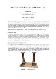
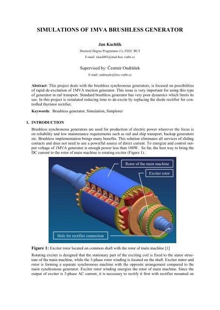
DC current to the rotor of main machine is rotating exciter (Figure 1).<br />
Hole for rectifier connection<br />
Rotor of the main machine<br />
Exciter rotor<br />
Figure 1: Exciter rotor located on common shaft with the rotor of main machine [1]<br />
Rotating exciter is designed that the stationary part of the exciting coil is fixed to the stator structure<br />
of the main machine, while the 3-phase rotor winding is located on the shaft. Exciter stator and<br />
rotor is forming a separate synchronous machine with the opposite arrangement compared to the<br />
main synchronous generator. Exciter rotor winding energize the rotor of main machine. Since the<br />
output of exciter is 3-phase AC current, it is necessary to rectify it first with rectifier mounted on
the shaft. Main disadvantage of this arrangement is poor dynamic of control output voltage [2], [3].<br />
Excitation winding in generator has enormous inductance and in magnetic field is stored a lot of<br />
energy, which cannot be quickly exhausted. The aim of this paper is to examine effective solution<br />
to the fast de-excitation of the brushless generator and thus suppress its major disadvantage.<br />
1.1. NECESSITY FOR RAPID DE-EXCITATION<br />
Modeled generator is used as an energy source for many diesel-electric locomotives. Generator<br />
through the rectifier energizes the serial excited DC traction motors. The locomotive is also<br />
equipped with an electromagnetic brake. This is such a condition of the vehicle, when train moves<br />
a certain speed and traction motors works in generator mode and train kinetic energy is transformed<br />
into electrical energy. To switch from driving mode to electromagnetic braking must be output<br />
voltage of the generator close to zero (de-excited rotor winding), then electric traction circuit has to<br />
be switched to braking mode (in electrodynamics braking mode traction motors has to realign to<br />
shunt connecting DC motors) and then re-energize the traction generator to the desired value. This<br />
whole process should run through due to safety and controllability of the locomotive as quickly as<br />
possible. Therefore it is necessary to explore possibilities of rapid de-excitation. Generator nominal<br />
values are shown in Table 1.<br />
Name Description Value<br />
Sn Output Power 1000KVA<br />
Un Output Voltage 407V<br />
In Current 1419A<br />
fn Frequency 90Hz<br />
nn Rotor Speed 1800min -1<br />
2. MODEL <strong>OF</strong> <strong>BRUSHLESS</strong> <strong>GENERATOR</strong><br />
Table 1: Nominal data of synchronous generator<br />
The model is created using Simplorer program, which includes a rich library of blocks for the<br />
simulation of multi-domain systems. The brushless generator model consists of two separate synchronous<br />
machines on a common shaft and on the outputs are 6-pulse rectifiers. As the load is used<br />
RL circuit to simulated nominal generator load. Model Parameters are shown in Table 2.<br />
2.1. EQUATIONS <strong>OF</strong> SYNCHRONOUS MACHINE<br />
In synchronous machines all flux-linkages, voltages, and currents are function of rotor angle.<br />
Therefore, is the better way to transform machine equation to coordinate system bound to the rotor<br />
(d-q) to speed up the calculation [4].<br />
Voltage equation:<br />
t d1d<br />
v1d t id<br />
t R1<br />
p<br />
t 1q<br />
t (1)<br />
dt<br />
t d1q<br />
v1q t iq<br />
t R1<br />
p <br />
t 1d<br />
t (2)<br />
dt<br />
v<br />
ed<br />
t i t t ded<br />
ed Re<br />
<br />
(3)<br />
dt
Flux-linkage equation:<br />
Where v1d, v1q, ved, id, iq, ied, d<br />
excitation winding.<br />
1d<br />
t id<br />
t L1d<br />
ied<br />
t Lm1ed<br />
(4)<br />
ed<br />
q<br />
(5)<br />
1q<br />
t iq<br />
t L1<br />
t id<br />
t Lm<br />
ed ied<br />
t Le<br />
1 (6)<br />
1 , 1q<br />
, ed<br />
are voltages, currents and flux-linkages in d-q axis and<br />
1<br />
Name Description Exciter Value Generator Value<br />
R1 Stator Resistance 24.8mΩ 2.29mΩ<br />
L1d Stator Inductance d-axis 0.868mH 1.195mH<br />
L1q Stator Inductance q-axis 0.458mH 0.621mH<br />
Lm1ed Mutual Inductance stator-exciter d-axis 13.93mH 66.45mH<br />
Re Excitation Resistance 4.02Ω 1.65Ω<br />
Le Excitation Inductance d-axis 643mH 6.017H<br />
p Number of Pole Pairs 6 3<br />
3. <strong>SIMULATIONS</strong> RESULTS<br />
Table 2: Parameters of the Exciter and the Generator<br />
The waveforms show the important electrical parameters at full excitation and de-excitation. At the<br />
time 6s excitation voltage drops to zero and the generator starts to de-excite. After about 0,8s excitation<br />
current drops to zero as shown in figure 2.<br />
Voltage (V)<br />
16<br />
14<br />
12<br />
10<br />
8<br />
6<br />
4<br />
2<br />
0<br />
00 22 44 66 88 10 10 12 12<br />
time (s)<br />
0<br />
Figure 2: Excitation voltage and current of exciter<br />
Voltage<br />
Current<br />
Figure 3 shows the output voltage of the exciter and current in main excitation winding. It can be<br />
seen that after voltage drops to zero current in the excitation winding flows 6 more seconds. This<br />
situation is very negative, because the train could not use electrodynamic brake before this time.<br />
Replacement commonly used diode rectifier for controlled thyristor rectifier would make it possi-<br />
4<br />
3.5<br />
3<br />
2.5<br />
2<br />
1.5<br />
1<br />
0.5<br />
Current (A)
le to change the polarity of the excitation voltage, which could termination of excitation current<br />
greatly accelerate. This solution is inspired by United States Patent [5].<br />
Voltage (V)<br />
100<br />
50<br />
0<br />
-50<br />
00 22 44 66 88 10 10 12 12<br />
time (s)<br />
-20<br />
Figure 3: Excitation voltage and current of the main machine<br />
Current (A)<br />
40<br />
35<br />
30<br />
25<br />
20<br />
15<br />
10<br />
5<br />
Figure 4: Comparison of the generator excitation currents<br />
Voltage<br />
Current<br />
Natural de-excitation<br />
Fast de-excitation<br />
0<br />
0 2 4 6 8 10 12<br />
time (s)<br />
As shown in figure 4, the time required to termination of excitation current is reduced to less than<br />
one third. This current directly corresponds to the output voltage of the generator as shown in figure<br />
5.<br />
40<br />
20<br />
0<br />
Current (A)
Voltage (V)<br />
600<br />
500<br />
400<br />
300<br />
200<br />
100<br />
0<br />
Figure 5: Comparison of the generator output voltages<br />
4. CONCLUSION<br />
By replacing the diode rectifier for controlled thyristor rectifier can be achieved significantly faster<br />
field weakening. With this design it is possible to use electrodynamic brake more efficient. Unfortunately,<br />
this solution does not take place without interference in the internal arrangement of the<br />
generator and brings other technical problems. Currently are examined other possibilities of rapid<br />
de-excitation with the emphasis on the simplest design.<br />
REFERENCES<br />
Natural de-excitation<br />
Fast de-excitation<br />
-100<br />
0 2 4 6 8 10 12<br />
time (s)<br />
[1] NĚMEC, J.,ONDRŮŠEK, Č.: Návrh rotujícího usměrňovače pro synchronní bezkroužkové<br />
generátory výkonů v jednotkách MVA. Elektrorevue [online]. 2007, roč. 2007, č. 34, s. 6<br />
[cit. 2012-03-01]. ISSN 1213 - 1539. Dostupné z:http://elektrorevue.cz/cz/clanky/energetika-<br />
-vykonova-elektronika--elektrotechnologie/0/navrh-rotujiciho-usmernovace-pro-synchronnibezkrouzkove-generatory-vykonu-v-jednotkach-mva---cast-1/<br />
[2] Smith, I.R.; Manning, C.D.; , "Brushless synchronous generator with rotating-thyristor excitation,"<br />
Electrical Engineers, Proceedings of the Institution of , vol.120, no.8, pp.901-902,<br />
August 1973<br />
[3] Erceg, G.; Erceg, R.; , "Specific applications of the transistor converter in excitation systems<br />
of synchronous generators," Electrical and Computer Engineering, 2001. Canadian Conference<br />
on , vol.2, no., pp.887-890 vol.2, 2001<br />
[4] KACHLÍK, J.; HUZLÍK, R. Simulation of Electric Vehicle in Simulink/ Simscape program.<br />
In LVEM 2011 Proceeding. Brno: VUT v Brně, 2011. s. 1-3. ISBN: 978-80-214-4362- 4.<br />
[5] WESTINGHOUSE ELECTRIC CORP., Pittsburgh, Pa. FAST DE-EXCITATION<br />
<strong>BRUSHLESS</strong> EXCITER [patent]. 841,773, 4,152,636. Granted May 1, 1979.